

Page 1
NELLCOR
N-200
Pulse
Operator’s
1988
Oximeter
Manual
NEL-15
Page 2
TABLE
}
Quick
Guide
to
|.
Operation
Introducing
the
NELLCOA
N-200
Pulse
OF
Oximeter
CONTENTS
Page
|.
ON.
IV.
Operating
Controls,
Basic
Use
Battery
Warnings
NELLCOR
Connecting
Connecting
Connecting
Connecting
Connecting
the
N-200
Displays,
Front
Panel
Rear
Panel
Patient
of
Pulse
Alarm
C-LOCK
Module
Operation
Special
Tone
Functions
ECG
Operating
Trend
and
Powerbase
Operation/Portable
Sensors
the
N-200
the
Other
the
Other
Setting
RS-232
Setting
the
Pin
the
and
Connectors
(Monitor)
(Powerbase)
Features
Synchronization
Modes
Event
NELLCOR
Memories
to
Other
Strip-Chart
Instruments
N-9000
Recorders
Hewlett-Packard
Digital
Baud
Assignments
RS-232
Devices
Rate
Communication
Use
Recorder/Intertace
ThinkJet
Printer
Port
Format
_
CG
O
UG
OD
ON
O
25
27
.
‚
27
27
28
29
29
29
30
ЗЕ:
Cpe
V.
Troubleshooting
Vi.
Principles
Vil.
Unpacking
VIII.
Service
IX.
Specifications
_
X.
Glossary
Xl.
Warranty
NELLCOR
OXISENSOR,
of
Operation
and
Checking
and
Maintenance
Configuration
Performance
Environmental
Electrical
Physical
Qualifying
and
Characteristics
Characteristics
Information
DURASENSOR
OXIBAND,
Guide
_
΄
the
Requirements
are
and
C-LOCK
N-200
registered
are
trademarks
trademarks
of
Nellcor
of
Nellcor
Incorporated.
Incorporated.
33
38
41
42
46
47
47
49
51
ㆍ
Page 3
|
QUICK
GUIDE
TO
OPERATION
1.
If
desired,
other
end
"Hospital
2.
Align
the
CONNECTION
(see
page
3.
If
C-LOCK™
4.
Select
the
5.
Press
6.
Check
For a quick
an
sensor
the
the
plug
one
into
a
properly
Grade"
red
dot
(see
on
socket
7).
Do
NOT
ECG
appropriate
directions
ON/STDBY
alarm
guide
limits.
to
using
end
of
the
power
grounded
page
7).
Alternatively,
the
connector
of
the
monitor,
twist.
synchronization
NELLCOR
for
use.
switch
If
necessary,
the
sensor
Plug
to
the
special
Basic
cord
to
100
to
120
at
the
end
and
push
is
to
be
used,
and
the
sensor
ON
position
adjust
features
Operation
the
NELLCOR®
vojt
AC
operate
of
the
the
connect
apply
into
the
(see
them
to
of
the
N-200,
outlet
marked
on
internal
patient
module
connector
an
appropriate
it
to
the
patient,
patient
page
7).
suit
the
needs
refer
N-200
pulse
"Hospital
battery
with
straight
following
module
to
of
the
(see
the
next
oximeter.
for
up
the
red
in
until
it
ECG
signal
the
pages 7 and
patient
page.
Plug
Only"
or
-
to
two
hours.
dot
on
the
locks,
(see
instructions
24).
(see
page
the
page
8).
7).
in
зы
..
5
|
2
.
一
一
!
Warning:
operating
manual
Warning:
for
complete
This
“Quick
the
NELLCOR
before
attempting
Carefully
description,
Guide
read
to
Operation”
N-200
the
pulse
clinical
use
directlons
Instructions,
Is
intended
oximeter.
of
the
instrument.
for
use
warnings,
`
only
Carefully
provided
cautions,
as a checklist
read
this
with
each
and
specifications.
for
operator's
NELLCOR
sensor
Page 4
oy
3
à
an
ail
1.
If
desired,
other
end
"Hospital
2.
Align
the
CONNECTION
(see
page
3. f C-LOCK"
4.
Select
the
5.
Press
6.
Check
For a quick
an
sensor
the
the
guide
plug
one
end
into a properly
Grade"
red
7).
appropriate
ON/STDBY
alarm
(see
dot
on
the
socket
Do
NOT
ECG
synchronization
directions
limits.
to
using
page
of
twist.
NELLCOR
for
switch
If
the
QUICK
of
the
power
grounded
7).
Alternatively,
connector
the
use.
necessary,
special
at
monitor,
is
sensor
Plug
the
to
the
features
GUIDE
Basic
cord
100
to
the
end
and
to
be
and
sensor
ON
position
adjust
TO
Operation
to
the
NELLCOR®
120
volt
AC
operate
of
the
patient
push
the
connector
|
used,
connect
apply
it
into
the
(see
them
to
of
the
N-200,
OPERATION
N-200
outlet
marked
on
internal
module
straight
an
appropriate
to
the
patient,
patient
page
suit
7).
the
refer
module
needs
to
pulse
“Hospital
battery
with
in
following
(see
of
the
the
next
oximeter.
Only”
for
up
to
the
red
dot
until
it
locks
ECG
signal
the
pages 7 and
patient
page.
Plug
the
or
two
hours.
on
the
(see
page
instructions
(see
page
in
24),
8).
7).
i
Warning:
operating
manual
Warning:
for
complete
This
“Quick
the
NELLCOA
before
attempting
Carefully
description,
Guide
read
to
Operation”
N-200
the
pulse
clinical
use
directions
instructions,
Is
intended
oximeter.
of
the
Instrument.
for
use
provided
warnings,
only
Carefully
with
cautions,
as a checklist
read
this
operator’s
each
NELLCOR
and
specifications.
for
sensor
A
Page 5
ise
Ton
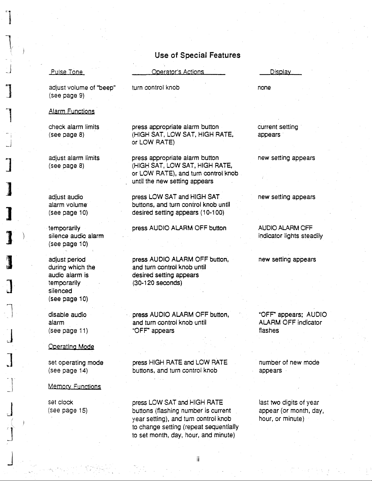
Use
of
Operator's
Special
Actions
Features
1
Le!
に
Eq
adjust
(see
Alarm
check
(see
adjust
(see
adjust
alarm
(see
-temporarily
silence
(see
adjust
during
audio
temporarily
silenced
(see
volume
page
9)
Functions
alarm
page
8)
alarm
page
8)
audio
volume
page
10)
audio
page
10)
period
which
alarm
page
10)
of
“beep”
limits
limits
alarm
the
is
turn
control
press
(HIGH
or
LOW
press
(HIGH
|
or
LOW
,
until
press
buttons,
desired
press
press
and
desired
(30-120
knob
appropriate
SAT,
LOW
RATE)
appropriate
SAT,
LOW
RATE),
the
new
setting
LOW
SAT
and
turn
setting
AUDIO
AUDIO
turn
appears
ALARM
ALARM
control
setting
seconds)
alarm
SAT,
alarm
SAT,
HIGH
and
turn
appears
and
HIGH
control
OFF
OFF
knob
until
appears
button
HIGH
RATE,
button
RATE,
control
SAT
knob
until
(10-100)
button
button,
knob
none
current
appears
new
new
AUDIO
indicator
new
setting
'
setting
setting
ALARM
setting
|
appears
appears
OFF
lights
appears
steadily
UI
‘
4
J
=
'
000
ーー
に
に
ως
É
,
Lo.
|
disable
alarm
(see
page
set
operating
(see
page
Memory
set
clock
(see
page
audio
©
11)
mode
14)
Functions
15)
-
press
and
“OFF”
press
buttons,
press
buttons
year
to
change
to
set
AUDIO
turn
ALARM
control
appears
HIGH
RATE
and
turn
LOW
SAT
(flashing
setting),
and
setting
month,
day,
knob
until
and
control
and
HIGH
number
tum
control
(repeat
hour,
OFF
button,
LOW
RATE
knob
RATE
is
current
knob
sequentially
and
minute)
“OFF”
ALARM
flashes
number
appears
last
appear
hour,
appears;
two
or
OFF
indicator
of
new
-
digits
(or
month,
minute)
mode
of
AUDIO
year
day,
-
Page 6
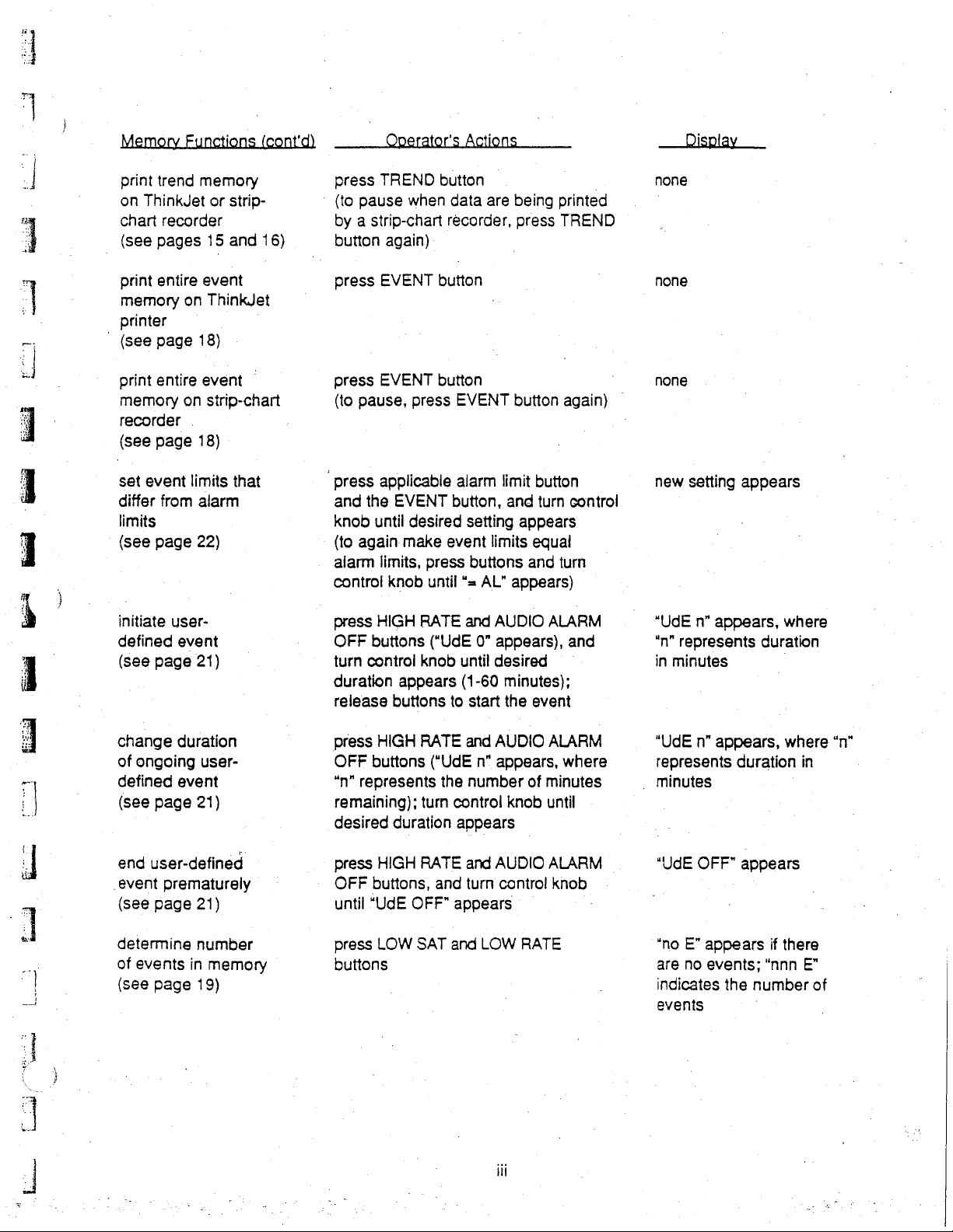
See
print
on
ThinkJet
chart
|
(see
print
memory
printer
©
(see
print
memory
recorder
(see
event
set
differ
limits
(see
initiate
defined
(see
trend
memory
or
recorder
pages
entire
page
entire
page
page
page
on
on
.
limits
from
user-
event
21)
15
event
ThinkJet
18)
event
strip-chart
18)
alarm
22)
strip-
and
16)
that
press
TREND
‘
(to
pause
by a strip-chart
button
press
press
(to
pause,
press
and
knob
(to
again
alarm
control
press
OFF
turn
duration
release
when
again)
EVENT
EVENT
press
applicable
the
EVENT
until
desired
make
limits,
press
knob
until
HIGH
RATE
buttons
control
knob
appears
buttons
button
data
recorder,
button
button
EVENT
alarm
button,
setting
event
buttons
“=
and
(“UdE
0”
until
(1-60
to
start
are
being
press
button
limit
and
appears
limits
and
AL”
appears)
AUDIO
appears),
desired
minutes);
the
printed
TREND
again)
button
turn
control
equal
turn
ALARM
and
event
|
none
none
none
new
setting
“UdE
n”
“n”
represents
in
minutes
appears
appears,
duration
where
change
of
ongoing
defined
(see
page
end
user-defined
event
prematurely
(see
page
determine
of
events
(see
page
duration
user-
event
21)
21)
number
in
memory
19)
press
HIGH
OFF
buttons
*n"
represents
remaining);
desired
press
OFF
until
press
buttons
duration
HIGH
buttons,
“UdE
OFF”
LOW
RATE
(“UdE
the
turn
control
appears
RATE
and
appears
SAT
and
and
AUDIO
n"
appears,
number
and
AUDIO
turn
contro!
LOW
ili
of
knob
©
RATE
ALARM
where
minutes
until
ALARM
knob
"UdE
n"
represents
.
minutes
“UdE
OFF"
“no
E”
are
no
indicates
events
appears,
duration
appears
appears
events;
the
number
where
if
there
“nnn
“n”
in
E”
of
Page 7
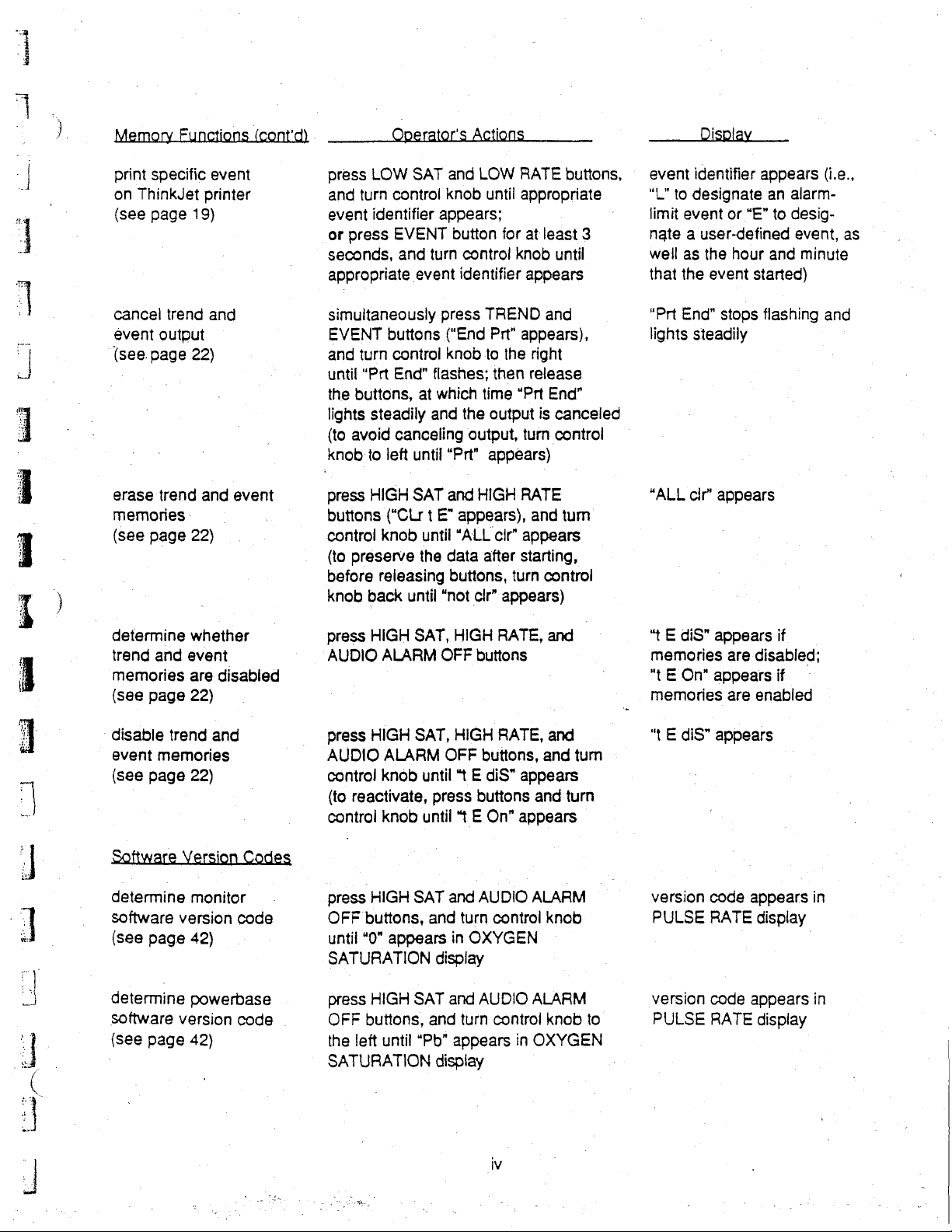
print
specific
on
ThinkJet
(see
page
cancel
event
(see
erase
memories-
(see
trend
output
page
trend
page
event
printer
19)
and
22)
and
|
22)
event
Operator's
press
LOW
SAT
and
turn
control
event
identifier
or
press
seconds,
appropriate
simultaneously
EVENT
and
until
the
lights
(to
knob
press
buttons
control
(to
before
knob
EVENT
and
buttons
turn
control
“Prt
End”
buttons,
steadily
avoid
canceling
to
left
HIGH
(“CLr t E”
knob
preserve
releasing
back
until
event
at
until
SAT
until
the
Actions
and
LOW
knob
until
appears;
button
turn
control
identifier
press
TREND
(“End
Prt”
knob
to
flashes;
which
and
time
the
output,
“Prt”
and
HIGH
then
output
appears)
appears),
“ALL
cir”
data
after
buttons,
“not
clr”
RATE
appropriate
for
at
least
knob
until
appears
and
appears),
the
right
release
“Prt
Ena”
is
canceled
turn
control
RATE
and
tum
appears
starting,
turn
control
appears)
buttons,
3
——
Display
event
identifier
“L"
to
designate
limit
event
or
nate a user-defined
well
as
the
hour
that
the
event
"Prt
End”
stops
lights
steadily
“ALL
cir’
appears
__
appears
an
alarm-
“E”
to
desig-
event,
and
started)
flashing
(i.e.,
as
minute
and
determine
trend
and
memories
(see
page
‘disable
event
memories
(see
page
Software
determine
software
(see
page
determine
software
(see
page
whether
event
are
22)
trend
and
22)
Version
monitor
version
42)
powerbase
version
42)
disabled
Codes
code
code
.
press
HIGH
AUDIO
press
AUDIO
control
(to
control
press
OFF
until
SATURATION
press
OFF
the
ALARM
HIGH
ALARM
knob
reactivate,
knob
HIGH
buttons,
“0”
appears
HIGH
buttons,
left
until
SATURATION
SAT,
HIGH
OFF
SAT,
HIGH
OFF
until
“t E diS”
press
until
+ E
SAT
and
and
in
display
SAT
and
and
"Pb"
appears
display
RATE,
buttons
RATE,
buttons,
buttons
On"
AUDIO
turn
control
OXYGEN
AUDIO
turn
control
and
and
and
appears
and
turn
appears
ALARM
knob
ALARM
knob
in
OXYGEN
|
turn
to
“t E diS”
appears
memories
"t E On"
memories
“ E diS”
version
PULSE
version
PULSE
appears
appears
code
RATE
code
RATE
are
disabled;
are
enabled
appears
display
appears
display
if
if
in
in
Page 8
i
dan
|.
m
:
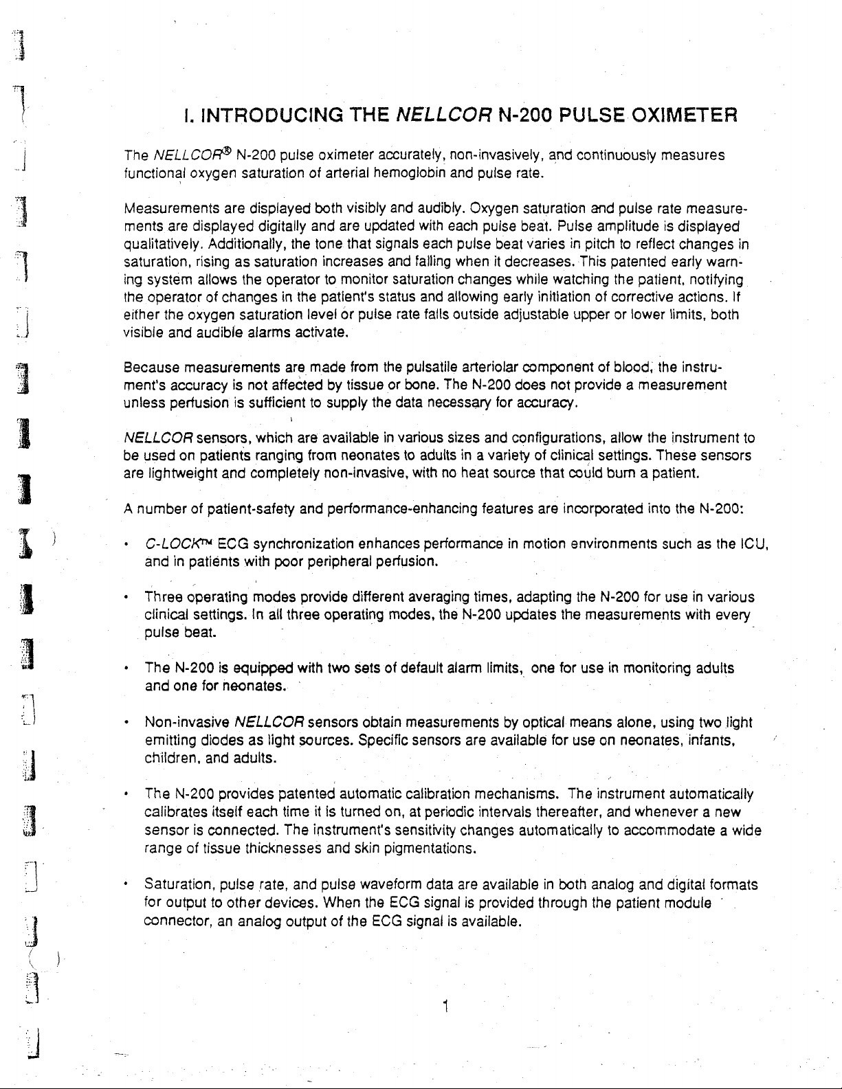
The
NELLCOR®
functional
INTRODUCING
N-200
oxygen
pulse
saturation
THE
oximeter
of
arterial
NELLCOR
accurately,
hemoglobin
non-invasively,
and
N-200
pulse
rate.
PULSE
and
continuously
OXIMETER
measures
Measurements
ments
qualitatively.
saturation,
ing
the
either
visible
Because
ment's
unless
NELLCOR
be
are
A
・
ㆍ
are
displayed
rising
system
operator
the
oxygen
and
audible
measurements
accuracy
perfusion
sensors,
used
on
lightweight
number
of
C-LOCK™
and
in
patiénts
Three
clinical
pulse
operating
settings.
beat.
Additionally,
allows
of
patients
patient-safety
are
displayed
digitally
the
as
saturation
the
operator
changes
saturation
is
is
and
ECG
in
alarms
are
not
affected
sufficient
which
ranging
completely
synchronization
with
poor
modes
In
all
three
both
visibly
and
are
tone
that
increases
to
monitor
the
patient's
level
or
activate.
made
by
tissue
to
supply
are
available
from
neonates
non-
-invasive,
and
performance-enhancing
updated
signals
status
pulse
from
the
the
in
and
and
saturation
rate
or
data
various
to
enhances
peripheral
provide
operating
perfusion.
different
modes,
audibly.
with
each
each
pulse
falling
when
changes
and
allowing
falls
outside
pulsatile
bone.
adults
with
arteriolar
The
necessary
sizes
in a variety
no
heat
performance
averaging
the
N-200
Oxygen
puise
beat
it
decreases.
early
adjustable
N-200
for
and
source
features
times,
updates
saturation
beat.
varies
while
initiation
component
does
accuracy.
configurations,
of
that
are
in
motion
adapting
and
Pulse
amplitude
in
pitch
This
watching
of
upper
of
not
provide a measurement
Clinical
settings.
could
incorporated
environments
the
N-200
the
measurements
pulse
rate
measure-
is
displayed
to
reflect
patented
the
corrective
or
lower
blood,
allow
burn a patient.
changes
early
patient,
actions.
limits,
the
instru-
the
instrument
These
into
the
such
for
use
with
notifying
sensors
N-200:
as
in
in
warn-
If
both
to
the
ICU,
various
every
。
The
N-200
and
one
・
Non-invasjve
emitting
children,
・
The
N-200
calibrates
sensor
range
ㆍ
Saturation,
for
of
output
connector,
is
equipped
for
neonates.
NELLCOR
diodes
and
adults.
provides
itself
is
connected.
tissue
thicknesses
pulse
to
other
an
analog
as
light
patented
each
rate,
devices.
with
two
sensors
sources.
time
it
is
The
instrument's
and
and
pulse
When
output
sets
obtain
Specific
automatic
turned
skin
waveform
the
of
the
ECG
of
default
alarm
measurements
sensors
calibration
on,
at
sensitivity
pigmentations.
ECG
signal
are
mechanisms.
periodic
changes
data
are
signal
is
is
available.
limits,
intervals
one
by
optical
available
thereafter,
automatically
available
provided
through
for
in
for
means
use
The
both
use
in
monitoring
alone,
on
neonates,
instrument
and
to
accommodate a wide
analog
the
patient
adults
using
two
light
infants,
automatically
whenever a new
and
digital
module
formats
*
Page 9

*
Twelve
ㆍ
hour
These
The
1
-.
一
一
i
上
even
一
1
一
一
?了
hours
of
saturation,
data
may
N-200
when
is
the
of
oxygen
pulse
be
provided
completely
monitor
is
saturation
rate,
and
to a variety
portable
and
detached
and
pulse
can
from
pulse
rate
perfusion
of
analog
operate
the
powerbase.
data
data
and
for
may
may
digital
up
to
two
be
stored
be
stored
output
hours
in
the
trend
in
the
event
devices.
on
its
internal
memory;
memory.
battery,
one
4
Loi
I
L
Page 10
Ii
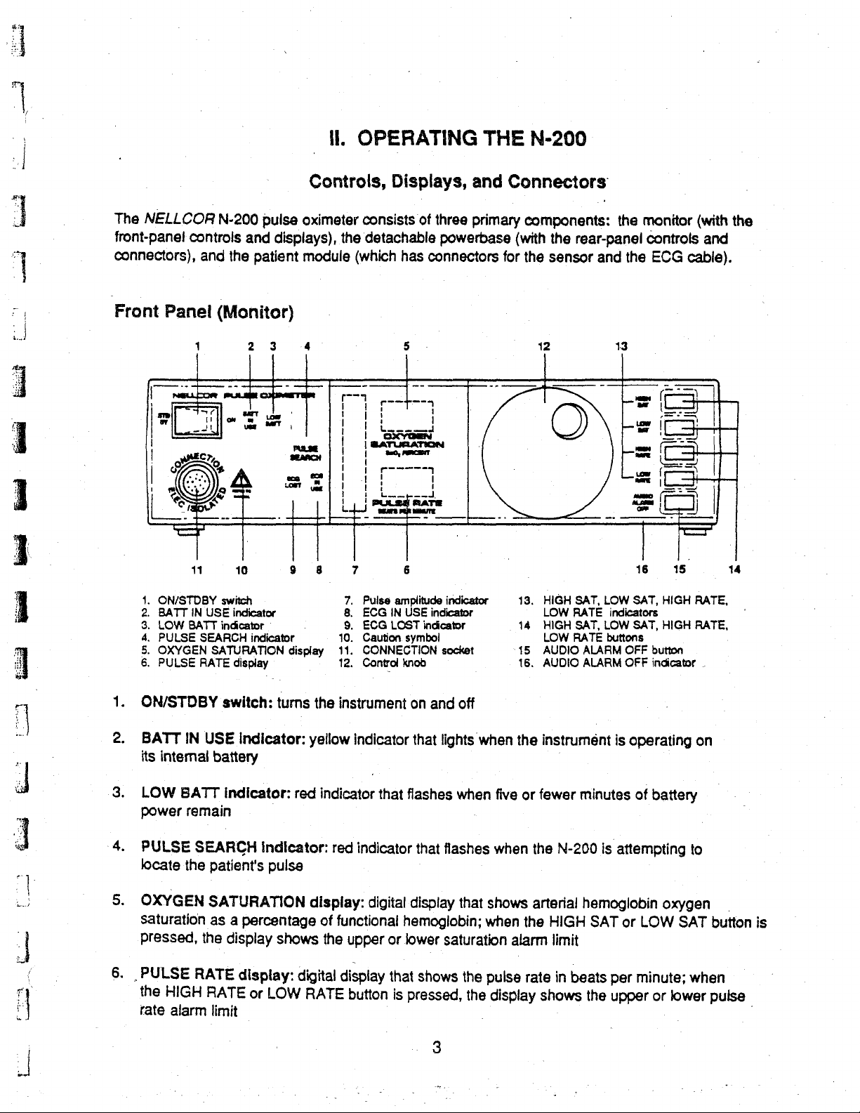
OPERATING
THE
N-200
The
NELLCOR
front-pane!
connectors),
Front
Panel
İ
=
|
v
|
|
1
mi
€,
|
controls
Eo
==
>
as
cs
11
N-200
and
and
the
patient
(Monitor)
1
st
Cr
2 3
m
>
ilem
고
où
NE
usa
NE
Q
je
ο
m
10
Controls,
pulse
oximeter
displays),
module
4 5
x
108
MT,
에
ei
μα
9
8
the
|
|
|
| |
1 P
니
(which
ーー
7
Displays,
consists
detachable
|
|
i
of
has
—
i
O
エーーーーー
1
m
bse
gare
connectors
|
コ
|
6
and
three
primary
powerbase
M
|
Connectors
components:
(with
the
rear-panel
for
the
sensor
12
O
the
and
13
7
-=
[=
-A
k)
monitor
controls
the
ECG
==
G
==
=
Sz
tow
|
LH
=.
000
|
16
cable).
—
ES
い
=
つい
~
15
(with
the
and
「
14
1.
2.
3.
4.
5.
6.
1.
ON/STDBY
2.
BATT
its
3.
LOW
power
4.
PULSE
locate
5.
OXYGEN
Saturation
pressed,
6.
PULSE
the
rate
ON/STDBY
BATT
IN
BATT
SEARCH
RATE
IN
BATT
remain
SEARCH
the
RATE
HIGH
alarm
USE
SATURATION
USE
battery
patient's
SAT
as
the
RATE
limit
LOW
PULSE
OXYGEN
PULSE
internal
switch
indicator
indicator
indicator
display
switch:
indicator:
a
display
turns
Indicator:
Indicator:
pulsa
URATION
percentage
shows
display:
or
LOW
-
display
the
yellow
red
indicator
display:
of
the
digital
RATE
7.
Pulse
8.
9.
10.
11.
12.
instrument
red
functional
upper
display
button
amplitude
ECG
IN
USE
ECG
LOST
Caution.
CONNECTION
Control
symbol
knob
on
indicator
indicator
digital
that
that
flashes
display
hemoglobin;
or
lower
that
is
pressed,
|
indicator
indicator
indicator
socket
and
off
lights
when
that
flashes
that
saturation
shows
when
when
the
the
.
13.
14
15
16.
the
five
or
when
the
shows
pulse
display
arterial
the
alarm
rate
HIGH
SAT,
LOW
HIGH
LOW
AUDIO
AUDIO
instrument
fewer
N-200
HIGH
limit
in
shows
LOW
RATE
indicators
SAT,
LOW
RATE
buttons
ALARM
ALARM
minutes
is
hemoglobin
SAT
beats
per
the
SAT,
HIGH
SAT,
HIGH
OFF
button
OFF
indicator
is
operating
of
battery
attempting
oxygen
or
LOW
minute;
upper
or
lower
RATE,
RATE,
to
SAT
when
.
.
on
button
pulse
is
|
3
Page 11
00000
E
gg
p
i
Pulse
indicates
.
ECG
lights
ECG
the
10.
A
11.
CONNECTION
12.
Control
specific:
limits,
13.
HIGH
to
indicate
indicator
14.
HIGH
alarm
modify
-trend
15.
AUDIO
with
or
disables
sets
user-defined
amplitude
pulse
IN
USE
steadily
LOST
extent
that
Caution:
knob:
buttons,
modifies
SAT,
which
flashes
SAT,
limits
various
and
event
ALARM
the
control
the
clock,
indicator:
amplitude
Indicator:
when
the
indicator:
the
N-200
Before
socket:
adjusts
the
control
various
LOW
SAT,
parameter
when
LOW
SAT,
to
be
displayed;
alarm
memories,
OFF
knob,
the
audio
disables
events
unlabeled
yellow
N-200
red
indicator
locks
indicator
can
no
longer
connecting,
connector
the
volume
knob
functions
HIGH
RATE,
is
beyond
the
upper
HIGH
RATE,
when
functions,
button:
changes
alarm;
and
set
and
set
temporarily
the
when
activates
vertical
that
onto
the
that
flashes
track
refer
to
Operator's
into
which
of
the
“beep”;
modifies
of
the
various
trend
LOW
the
established
pulse rate.
LOW
used
in
conjunction
alarm
and
the
operating
silences
period
used
during
in
conjunction
the
trend
column
flashes
signal
if
the
it
the
patient
when
and
event
RATE
RATE
Indicators:
alarm
limit
buttons:
event
mode
which
and
of
when
ECG
Manual
used
alarm
memories,
alarm
is
with
limits,
the
audio
the
with
event
light
bars
that
the
N-200
signal
module
functions,
is
is
plugged
in
conjunction
sets
and
flashes
limit
(e.g.,
exceeded)
when
pressed,
the
control
modify
audio
the
memories,
various
alarm;
alarm
control
when
qualitatively
locates
lost
or
if
an
it
|
with
alarm
sets
the
during
the
the
HIGH
cause
knob,
these
functions
used
is
temporarily
knob
and
and
initiates
ECG
signal;
deteriorates
and
event
operating
alarm
state
RATE
the
current
buttons
of
the
in
conjunction
silenced
other
buttons,
and
modifies
to
‘Arai
ir
dio
=
vey
viro
mea
16.
AUDIO
silenced;
ALARM
flashes
OFF
indicator:
when
the
audio
lights
steadily
alarm
has
when
been
the
disabled
audio
alarm
has
been
temporarily
Page 12
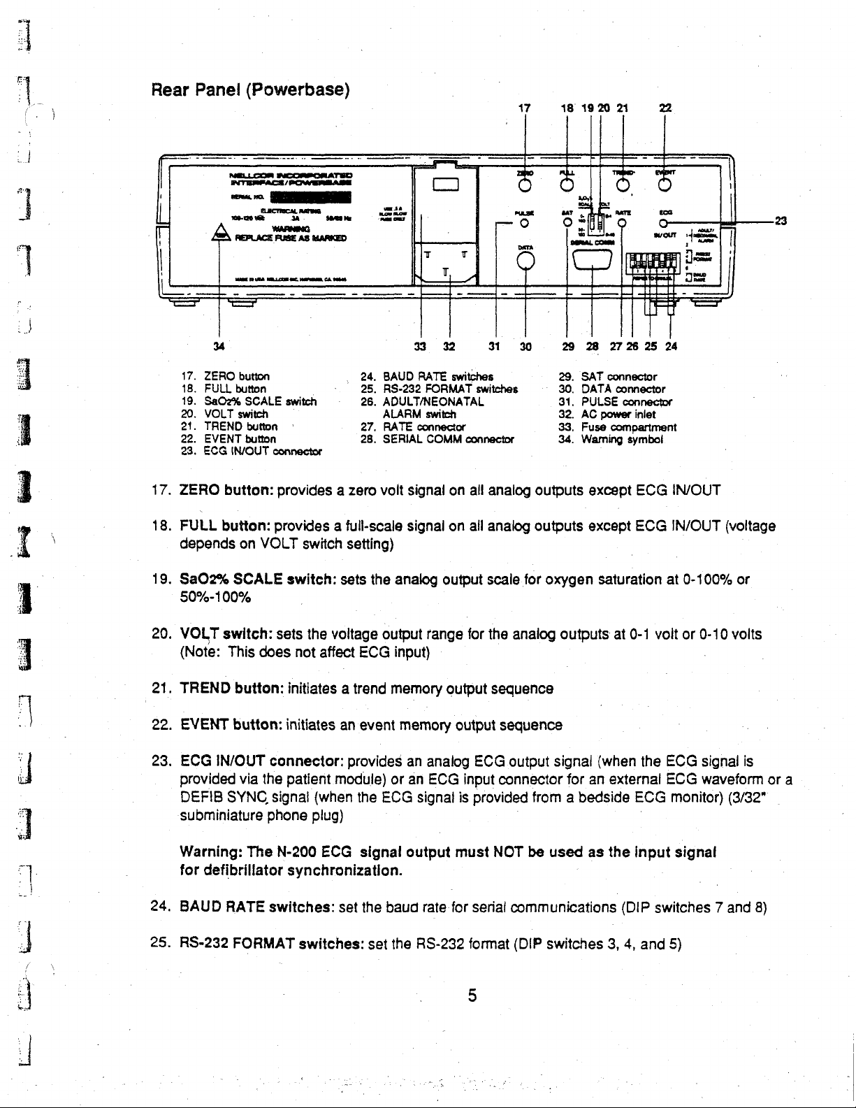
Rear
Panel
(Powerbase)
47
18
19
20
21
22
il
17.
18.
A
À
34
17.
ZERO
18.
FULL
19.
SaOz%
20.
VOLT
21.
TREND
22.
EVENT
23.
ECG
ZERO
FULL
depends
button:
button:
a
ELÆCTERCAL
106-120
vé
JA
renace
ens
REPLACE
FUSE
TRAI
ER
RA
НИИ.
-
button
button
SCALE
switch
button
button
IN/OUT
on
NAČ,
-
switch
|
|
connector
provides a zero
provides a full-scale
VOLT
바구
RATER
Sa.
AS
MARKED
OMPI,
EA
ーー
switch
A
|
e
“PNR
|
USAS
=
‚
24,
25.
-
26.
27.
28.
setting)
ar
CI
nale
CUS
T
N
T
ー
33
BAUD
RS-232
ADULT/NEONATAL
ALARM
RATE
SERIAL
volt
signal
signal
_
32
RATE
switches
FORMAT
switch
connector
COMM
on
on
T
AA
31
30
switches - 30.
connector
all
all
analog
analog
outputs
outputs
29 28
29.
SAT
DATA
31.
PULSE
32.
AC power
33,
Fuse
34.
Warning
except
except
2726
25 24
connector
connector
connector
inlet
compartment
symbol
ECG
ECG
IN/OUT
IN/OUT
(voltage
19.
Sa02% SCALE
50%-100%
20.
VOLT
(Note:
21.
TREND
22.
EVENT
23.
ECG
provided
DEFIB
subminiature
Warning:
for
defibrillator
24.
BAUD
25.
RS-232
switch:
This
does
button:
button:
IN/OUT
via
SYNC
The N-200
RATE
FORMAT
switch:
sets
not
initiates a trend
initiates
connector:
the
patient
signal
phone
synchronization.
switches:
sets
the
voltage
affect
an
module)
(when
plug)
ECG
set
switches:
the
analog
output
ECG
input)
memory
event
memory
provides
or
the
ECG
signal
the
baud
set
the
output
range
output
an
analog
an
ECG
signal
output
rate
for
RS-232
scale
for
the
sequence
output
must
sequence
ECG
input
connector
is
provided
NOT
serial
format
for
oxygen
analog
output
communications
signal
from a bedside
be
used
(DIP
switches
saturation
outputs
(when
for
an
as
at
0-1
volt
the
external
ECG
the
input
(DIP
switches 7 and
3,
4,
and
at
0-100%
or
0-10
ECG
signal
ECG
waveform
monitor)
signal
5)
or
volts
is
or
(3/32"
8)
a
—
Page 13
aiment
|
ADULT/NEONATAL
26.
(DIP
RATE
27.
“0-250
28.
SERIAL
connector
SAT
29.
0-100%
30.
DATA
interface
31.
PULSE
32.
AC
power
33.
Fuse
34.
AA
switch
1)
connector:
bpm
(3/32"
COMM
connecter:
or
50%-100%
connector:
or a NELLCOR
connector:
inlet
compartment
warning:
ALARM
provides
subminiature
connector:
provides
(3/32"
provides
N-8000
provides
Risk
of
fire.
switch:
analog
provides
anaiog
fiber
output
phone
output
subminiature
optic
interface
analog
Replace
sets
the
of
plug)
RS-232
of
oxygen
phone
output
output
fuse
as
defauit
pulse
rate
digital
saturation
plug)
for
connection
of
pulse
marked.
alarm
limits
in
beats
interface
—
to a NELLCOR
waveform
for
adults
per
minute,
via a nine-pin
data
(%SaQ2),
(3/32"
subminiature
or
neonates
with a range
“D"-type
with a range
N-9000
recorder/
phone
of
of
piug)
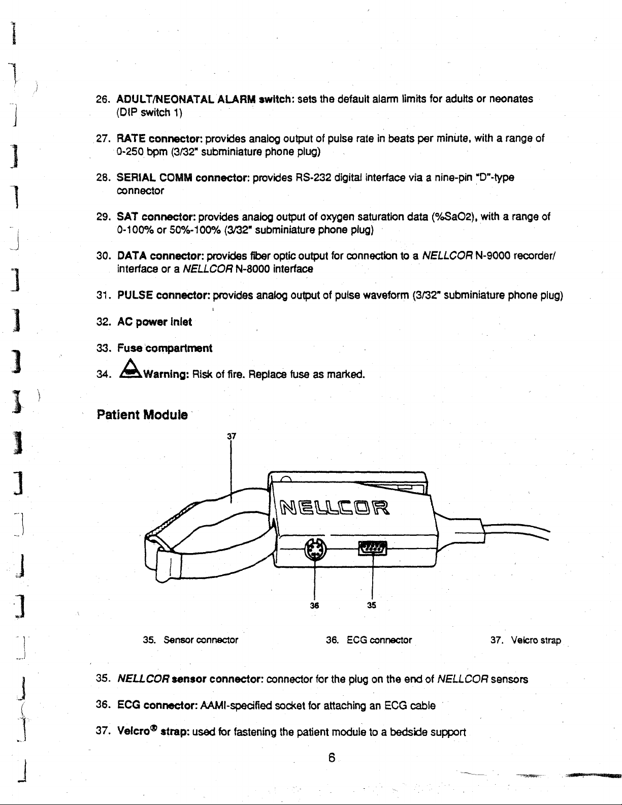
Patient
Module
37
LA.
i
1
a
!
i
|
に
っ
4
i
ic
,
4
35.
36.
35.
NELLCOR
ECG
connector:
Sensor
sensor
connector
connector:
AAMI-specified
36
connector
socket
for
for
—
36.
the
attaching
as
ECG
connector
plug
an
on
the
ECG
\
end
cable
of
NELLCOR
37.
Velcro
sensors
strap
|
37.
Velero©
strap:
used
for
fastening
the
patient
module
6
to a bedside
support
Page 14
Basic
Operation
ba
Warning:
read
the
1.
if
desired,
N-200.
Only”
battery.
Never
grade
If
the
ted
itlocks.
Use
20
patient
C-13
lf
C-LOCK
trodes
the
into
waveform
C-LOCK
Improper
“Warnings”
plug
Plug
or
“Hospital
use
an
AC
power
patient
dot
on
the
Do
the
NELLCOR
module.
C/D
or
ECG
to
the
lead
wires
the
patient
(high-level
ECG
use
of
the
section
one
end
of
the
other
end
Grade.”
outlet
that
does
plug
and
cord
module
is
disconnected,
CONNECTION
NOT
twist
the
connector
C-200-13
(If
the
ECG
C-20 C/D
patient
into
module;
synchronization
patient
synchronization
in
standard
the
ECG
alternatively,
output)
N-200
of
the
into a properly
Alternatively,
could
this
manual
power
not
cord
operate
have a grounding
or
an
equivalent
align
socket
on
the front
while
patient
module
cable
module,
connector
may
is
to
be
limb
lead
(observing
used,
connect
from
an
ECG
enhances
stability | in
present a hazard
before
into
grounded
the
attaching
on
be
configuration,
monitor
clinical
the
AC
the
hospital-
red
dot
of
which
the
patient
used
provide
correct
the
DEFIB
to
power
100
to
N-200
connection.
grade
on
the
N-200.
it.
is
supplied
module
instead.)
an
attach
limb
the
high-motion
to
the
patient.
use
of
the
inlet
on
the
120
volt
AC
for
up
to
two
Use
only
plug.
the
patient
ECG
connections),
SYNC
N-200
module
Push
the
with
the
is
not
signal
lead
wires
puise
ECG
IN/OUT
or
low-perfusion
Carefully
instrument.
back
of
the
NELLCOR
outlet
marked
hours
on
the
original
connector
connector
N-200,
necessary, a NELLCOR
as
follows:
to
the
and
plug
output
or
connector.
“Hospital
its
internal
hospital-
with
straight
or
the
C-200-
apply
ECG
electrodes,
the
ECG
the
ECG
OUT
cable
environments.
the
in
until
elec-
piug
See
the
“Use
of
Select
use
Turn
The
Circuitry.
and
synchronization
After
beat-to-beat
“beep”
indicator
alarm
an
appropriate
provided
the
with
instrument
instrument
Then
the
PULSE
four
RATE
to
six
information.
rises
as
begins
limits
in
effect
Special
Features”
NELLCOR
the
sensor.
on
by
moving
emits a “beep”
PULSE
displays
is
being
pulses,
oxygen
to
follow
SEARCH
used
the
digital
The
saturation
the
(see
page 9 for
show a non-flashing
pulse.
section
sensor
Plug
the
sensor
the
ON/STDBY
and
all
displays
indicator
and
an
ECG
OXYGEN
instrument
increases
At
this
the
of
this
manual
and
apply
it
to
into
the
switch
light
momentarily
begins
to
zero.
signal
is
detected.
SATURATION
emits a “beep”
and
falls
time,
the
alarms
default
limits).
for
the
patient,
patient
to
the
flash,
The
ECG.IN
and
with
as
it
decreases.
are
full
instructions.
following
module.
ON
position.
while
the
and
the
OXYGEN
USE
PULSE
each
puise,
The
operational,
the
N-200
display
RATE
and
pulse
displays
the
with
directions
tests
for
its
SATURATION
illuminates
if
begin
pitch
of
the
amplitude
the
default
ECG.
to
show
Page 15
Normally,
typically
bars,
indicator
actions
lower
perfusion
will
to
for
adults
begin
take
the
for
neonates.
is
inadequate
to
in
this
pulse
amplitude
If
the
to
enable
flash.
(See
the
situation.)
pulse
indicator
amplitude
the
N-200
reaches
to
“Troubleshooting
|
at
indicator
track
shows
the
Guide”
least
mid-scale,
pulse
in
this
less
than
and
manual
while
it
is
two
to
three
the
PULSE
SEARCH
for a discussion
light
of
When
sensor,
Be
sure
instrument.
6.
Check
LOW
To
adjust
button
desired
100%,
minute.
When
values.
7.
To
tum
If
it
is
connector
the
instrument
with
each
to
familiarize
the
alarm
SAT,
HIGH
the
alarm
(HIGH
and
the
necessary
SAT,
value
is
the
The
upper
instrument
the
N-200
and
is
receiving a signal
pulse
beat
yourself
limits
each
RATE,
limits
LOW
displayed.
pulse
rate
limit
must
is
turned
off,
move
to
disconnect
pull
straight
the
time
and
to
meet
SAT,
Oxygen
alarm
be
the
out.
instrument
with
the
the
LOW
RATE
the
HIGH
saturation
limits
higher
off
and
ON/STDBY
the
patient
Do
NOT
from
emits a high-pitched
different
N-200
is
vuttons.
needs
RATE,
may
of a specific
or
be
than
the
back
on
switch
module,
twist
the
pulse
used,
Each
LOW
alarm
set
for
lower
again,
grasp
the
connector
ECG
electrodes
tones
by
sequentially
limit
patient,
RATE),
limits
may
any
value
limit.
the
alarm
to
the
STDBY
the
tone
before
will
be
press
and
turn
be
set
from
limits
position.
textured
while
unplugging
but
not
frorn a NELLCOR
that
has a slight
clinical
use
pressing
`
the
displayed.
and
hold
the
control
for
any
35
to
250
return
to
metal
surface
of
the
HIGH
the
knob
value
beats
the
default
it.
warble.
SAT,
appropriate
until
the
from
50%
to
per
of
the
Page 16
AI
Pulse
Tone
Use
ot
Special
Features
ーー
When a NELLCOR
“peep”
and
saturation
status
When
beat
“beep”
accompanies
tone
instrument,
the
To
back
Alarm
The
lf
limits,
audio alarm
falling
and
the
is
also
“beep”
adjust
on
N-200
the
alarms
the
that
varies
as
it
decreases.
changes
allowing
N-200
signaled
heard
when a sensor-derived
an
is
significantly
be
sure
that
changes
the
volume
again,
the
Functions
has
both
activate
corresponding
will
sensor
in
pitch
while
prompt
is
receiving
by a high-pitched
ECG-derived
to
pulse
visible
sound
is
connected
to
reflect
This
watching
initiation
only
signal
higher
familiarize
pitch
of
the
pulse
tone
than
with
returns
and
because
(unless
the
alarm
or
patented
audible
indicator
to
changes
the
patient,
of
corrective
an
ECG-derived
tone
that
signal
is
NOT
any
“beep”
yourself
oxygen
tone,
turn
to
its
alarms
oxygen
will
until
it
has
the
N-200
in
oxygen
early
warning
notifying
actions
signal
has a slight
is
present.
related
that
with
the
difference
saturation.
the
control
defauit
saturation
that
flash,
been
turned
volume.
activate
the
and a patient,
saturation,
system
the
operator
(U.S.
(no
warble.
The
pitch
to
oxygen
reflects
knob.
level
or
appropriate
off).
rising
allows
Patent
sensor-derived
This
of
saturation.
oxygen
between
When
as
described
pulse
display
the
pulse
as
saturation
the
operator
of
changes
4,653,498).
signal),
tone
is
distinct
the
warbling
The
saturation.
the
ECG
.
the
N-200
below.
rate
moves
will
beat
is
to
in
the
from
tone
pitch
Before
warbling
is
turned
beyond
flash,
signaled
increases
monitor
patient's
each
pulse
any
that
of
the
warbling
using
tone
off
and
the
alarm
and
an
by
the
and
a
|
lf
the
alarms
displays
(unless
If
the
alarms
become
until
it
If
the
alarm
The
audio
disabled,
dy
will
or
until
blank,
has
been
alarm
and
activate
flash
zero,
it
has
activate
the
PULSE
turned
activates
function
its
volume
because
the
PULSE
been
turned
because
SEARCH
off).
because
can
can
the
pulse
SEARCH
off).
the
sensor
the
ECG
be
altered
be
adjusted.
signal
is
indicator
or
patient
indicator
signal
in
several
The
will
is
visible
lost,
the
module
flash,
lost,
the
ways:
alarm
OXYGEN
will
flash,
and
red
it
SATURATION
and
an
is
disconnected,
an
audio
ECG
LOST
can
be
temporarily
cannot
be
audio
alarm
the
alarm
will
indicator
silenced,
modified.
and
PULSE
will
displays
sound
will
(unless
flash.
it
sound
will
can
RATE
or
be
Page 17
Default
are
two
Alarm
sets
Limits:
of
default
Default
alarm
alarm
limits,
one
limits
are
for
monitoring
in
effect
when
adults
the
and
N-200
one
for
is
turned
monitoring
on.
There
neonates.
high
low
high
low
To
determine
button
appears
To
of
be
Adjusting
the
or
When
Warning:
immediately
in
change
the
powerbase
operating
HIGH
to
the
left
the
Alarm
Limit
oxygen
oxygen
pulse
rate
pulse
rate
whether
the
OXYGEN
the
adult/neonatal
(DIP
on
AC power
the
Audio
SAT
and
to
decrease
N-200
Do
is
not
turned
set
saturation
saturation
the
default
after
turning
SATURATION
setting,
switch
Alarm
LOW
the
when
SAT
it.
off
alarm
1),
Volume:
buttons,
and
Adult
100%
85%
140
beats/minute
55
beats/minute
alarm
on
using a slender,
the
back
volume
limits
the
N-200.
display;
move
setting
To
and
on
are
if
the
is
changed
adjust
turn
again,
too
low
Setting
|
set
for
an
adult
the
instrument
if
it
is
set
for a neonate,
ADULT/NEONATAL
nonmetallic
the
audio
the
control
the
audio
to
be
for
that
alarm
knob
alarm
heard.
object.
Neonatal
95%
-
80%
200
100
or a neonate,
is
set
for
an
“95”
ALARM
Note:
The
change
volume,
to
to
the
right
returns
to
be
press
Setting
ㆍ
beats/minute
beats/minute
press
the
adult,
"100"
appears.
switch
implemented.
to
the
on
N-200
and
hold
increase
default
the
must
volume.
HIGH
both
the
SAT
back
volume
Temporarily
the
AUDIO
that
the
audio
if
the
alarm
To
change
ALARM
OFF
SATURATION
120
seconds.
When
the
N-200
Silencing
ALARM
alarm
state
continues.
the
period
button
dispiay.
is
the
OFF
button
has
been
during
down,
Then
turned
off
Audio
Alarm:
once.
temporarily
which
the
and
turn
the
release
and
back
The
red
silenced.
audio
control
the
button.
on
again,
To
silence
AUDIO
alarm
knob
This
this
the
audio
ALARM
After
60
seconds,
is
temporarily
until
the
period
period
can
returns
alarm
OFF
indicator
silenced,
desired
be
set
to
for
60
the
alarm
hold
period
for
any
60
seconds.
seconds,
lights
steadily
will
again
the
AUDIO
appears
value
press
to
sound
in
the
OXYGEN
between
show
30
and
10
Page 18
}
Disabling
button
audio
safety
To
the
then
again
the
temporarily
alarm
could
disable
right
begins
(and
AUDIO
the
by
be
the
until
“OFF”
flashing.
the
ALARM
Audie
Alarm:
silences
following
compromised.
audio
alarm,
appears
The
AUDIO
ALARM
OFF
Warning—in
the
the
instructions
hold
on
the
audio
OFF
button
(and
audio
the
AUDIO
OXYGEN
alarm
indicator
the
alarm.
can
be
AUDIO
normal
operation,
While
below,
ALARM
SATURATION
reactivated
then
goes
ALARM
it
this
OFF
out).
the
is
possible
should
button
display.
by
pressing
Then
OFF
indicator
AUDIO
not
down,
it
to
disable
be
done
and
The
the
can
be
begins
ALARM
if
turn
AUDIO
AUDIO
disabled
flashing
ΟΕΕ
the
patient
the
control
ALARM
ALARM
again
again).
knob
OFF
OFF
by
pressing
to
indicator
button
J
u
When
function.
Warning:
ALARM
adverse
situations
To
patient
identify
ECG
accurate
Connecting
ECG
or
If
red
lf
Guide”
patient,
continues
-
synchronization
ALARM
the
instrument
When
OFF
patient
in
C-LOCK
provide
synchronization,
signal
has
the
heart
ECG
more
poor
pulse
the
from
alternatively,
the
ECG
signal
ECG
LOST
that
is
not
the
in
this
oximeter
to
search
OFF
button.
is
turned
the
AUDIO
indicator
Is
illuminated,
condition.
which
patlent
1
Synchronization
reliable
perfusion,
and
rate
ECG
two
from a bedside
is
indicator
source
manual.
measurements
again
saturation
the
synchronize
enhances
display.
Signal:
sources:
lost
or
deteriorates
flashes.
of
the
When
for
an
ECG
becomes
off
and
ALARM
The
AUDIO
safety
could
measurements
N-200
the
performance
As
described
directly
ECG
IF
THIS
problem,
the
ECG
derive
signal,
active.
back
on
OFF
button
no
audio
ALARM
be
can
use
saturation
on
from
the
monitor
to
the
via
extent
HAPPENS,
follow
the
signal
from
and,
To
cancel
is
the
when
again,
the
has
alarm
OFF
audio
been
will
button
compromised.
in a high-motion
an
ECG
(R-wave)
measurements.
while
maintaining
the
following
patient
via a conventional
an
interconnection
that
the
FIRST
CHECK
suggestions
lost,
if a NELLCOA
optical
it
tracks
the
ECG
signal
an
LOST
alarm
pressed
sound
in
should
environment
signal
This
rapid
pages,
the
cable.
N-200
can
THE
outlined
sensor
alone.
adequate
indicator,
returns
and
the
not
feature,
response
to
the
event
be
as a time
N-200
three-lead
no
longer
STATUS
in
the
“Troubleshooting
is
connected
During
this
signal,
press
its
normal
red
AUDIO
of
used
or
when
reference
known
time
can
receive
track
OF
time
C-LOCK
the
in
-
as
and
ECG
it,
THE
the
AUDIO
a
to
C-LOCK
an
an
cable,
the
PATIENT.
to
the
N-200
ECG
7
„V
|
|
κ...
m
я
When
muscular
-
signal
C-LOCK
using
activity
alone
ECG
C-LOCK
for
ECG
may
disrupt
obtaining
synchronization,
measurements.
synchronization
the
ECG
signal
When
automatically
an
electrocautery
and
causa
an
begins
the
adequate
functioning.
11
unit
N-200
ECG
or
significant
to
begin
using
signal
is
upper-body
the
again
available,
optical
Page 19
Зона
a
Default
are
O
O
O
i
了
|
To
button
appears
To
of
be
Adjusting
the
or
Alarm
two
sets
ㅡ
high
low
high
low
determine
immediately
in
change
the
powerbase
operating
HIGH
SAT
to
the
left
Limits:
of
default
00800
oxygen-saturation
oxygen
pulse
pulse
whether
the
OXYGEN
the
adult/neonatal
on
AC
the
Audio
and
to
decrease
Default
alarm
ini
saturation
rate
rate
the
after
turning
(DIP
switch
power
Alarm
LOW
it.
一
default
SATURATION
SAT
alarm
limits,
one
©»
-
alarm
on
the
setting,
1),
using a slender,
when
the
setting
Volume:
buttons,
limits
for
monitoring
100%
140
limits
N-200.
display;
move
To
adjust
and
are
in
effect
adults
Adult
85%
55
setting
:
beats/minute
beats/minute
are
set
for
If
the
instrument
if
it
is
set
the
ADULT/NEONATAL
nonmetallic
is
changed
the
audio
turn
the
control
when
the
N-200
and
one
.
an
adult
or a neonate,
is
set
for a neonate,
object.
for
that
change
alarm
volume,
knob
to
is
for
Neonatal
200
100
for
ALARM
Note:
to
the
right
turned
monitoring
on.
Setting
95%
80%
beats/minute
beats/minute
press
an
adult,
“100"
“95”
appears.
switch
The
N-200
be
implemented.
press
and
to
increase
There
neonates.
the
HIGH
on
the
back
must
hold both
the
volume
SAT
When
‚
Warning:
Temporarily
the
that
if
To
the
AUDIO
the
the
alarm
change
ALARM
SATURATION
120
seconds.
When
the
N-200
Do
ALARM
audio
state
the
OFF
N-200
is
turned
not
set
Silencing
OFF
alarm
has
continues.
period
button
during
down,
display.
is
turned
off
the
alarm
the
button
been
Then
off
and
back
volume
Audio
Alarm:
once.
temporarily
which
the
and
turn
the
release
and
back
on
again,
too
The
red
silenced.
audio
control
the
button.
on
again,
low
To
silence
AUDIO
alarm
the
to
knob
This
this
audio
alarm
be
heard.
the
audio
ALARM
After
60
seconds,
is
temporarily
until
the
desired
period
period
can
returns
returns
alarm
OFF
to
for
indicator
the
silenced, hold
period
be
set
for
to
60
the
default
60
seconds,
lights
alarm
will
the
appears
any
value
seconds.
volume.
press
steadily
again
to
sound
AUDIO
in
the
OXYGEN
between
—
show
30
and
도
ων
A
10
Page 20
:
|
Disabling
button
audio
safety
To
the
then
again
the
When
temporarily
alarm
could
disable
right
until
begins
(and
AUDIO
the
instrument
function.
Warning:
ALARM
adverse
Situations
When
OFF
patient
C-LOCK
To
provide
patient
identify
ECG
accurate
has
the
synchronization,
heart
the
Audio
by
following
be
compromised.
the
audio
“OFF”
flashing.
the
AUDIO
ALARM
the
indicator
condition.
in
which
ECG
Synchronization
more
reliable
poor
perfusion,
pulse
and
rate
Alarm:
silences
the
alarm,
appears
OFF
is
AUDIO
patient
display.
hold
The
audio alarm
ALARM
button
turned
is
illuminated,
saturation
the
synchronize
enhances
Warning—ln
the
audio
instructions
the
AUDIO
on
the
OXYGEN
OFF
indicator
(and
the
off
and
ALARM
The
AUDIO
safety
could
measurements
N-200
the
performance
normal
alarm.
below,
ALARM
SATURATION
can
be
reactivated
then
AUDIO
back
on
again,
OFF
button
no
audio
ALARM
be
compromised.
can
use
an
saturation
while
operation,
While
it
is
possible
this
should
OFF
button
by
goes
out).
ALARM
alarm
OFF
ECG
measurements.
OFF
the
audio
has
been
will
button
in a high-motion
(R-wave)
maintaining
the
AUDIO
not
down,
display.
pressing
Then
it
indicator
alarm
pressed
sound
in
should
environment
signal
This
rapid
ALARM
to
disable
be
done
and
The
AUDIO
the
AUDIO
can
be
begins
returns
and
the
the
event
not
be
as a time
feature,
response
the
if
patient
turn
the
ALARM
ALARM
disabled
flashing
to
its
normal
red
of
used
or
reference
known
time
OFF
control
again
again).
AUDIO
in
when
as
C-LOCK
and
knob
OFF
OFF
by
a
to
an
to
indicator
button
pressing
Mu
A
이
ted
Connecting
ECG
signai
or
alternatively,
If
the
ECG
red
ECG
If
that
is
Guide”
patient,
continues
synchronization
ALARM
When
using
muscular
Signal
b
alone
C-LOCK
the
from
signal
LOST
not
the
in
this
manual.
oximeter
to
search
OFF
button.
C-LOCK
activity
for
ECG
synchronization
ECG
Signal:
two
sources:
from a bedside
is
lost
or
deteriorates
indicator
source
flashes.
of
the
When
measurements
for
an
ECG
again
becomes
ECG
synchronization,
may
disrupt
obtaining
measurements.
As
described
directly
ECG
IF
problem,
the
derive
signal,
active.
the
monitor
THIS
ECG
ECG
from
to
the
HAPPENS,
follow
signal
from
and,
To
cancel
signal
When
automatically
on
the
following
the
patient
via
extent
via a conventional
an
interconnection
that
the
FIRST
the
suggestions
is
lost,
if a NELLCOR
the
optical
when
an
electrocautery
and
an
begins
signal
it
tracks
the
ECG
cause
the
adequate
functioning.
pages,
N-200
CHECK
outlined
alone.
an
adequate
LOST
unit
N-200
ECG
the
N-200
three-lead
cable.
can
no
longer
THE
STATUS
in
the
sensor
indicator,
or
to
signal
is
During
signal,
press
significant
begin
is
cán
receive
track
OF
THE
“Troubleshooting
connected
this
time
C-LOCK
the
ECG
it,
to
the
ECG
AUDIO
an
cable,
the
PATIENT.
the
N-200
upper-body
using
the
optical
again
available,
14
Page 21
cuni
Warning:
used
Warning:
be
connected
to
that
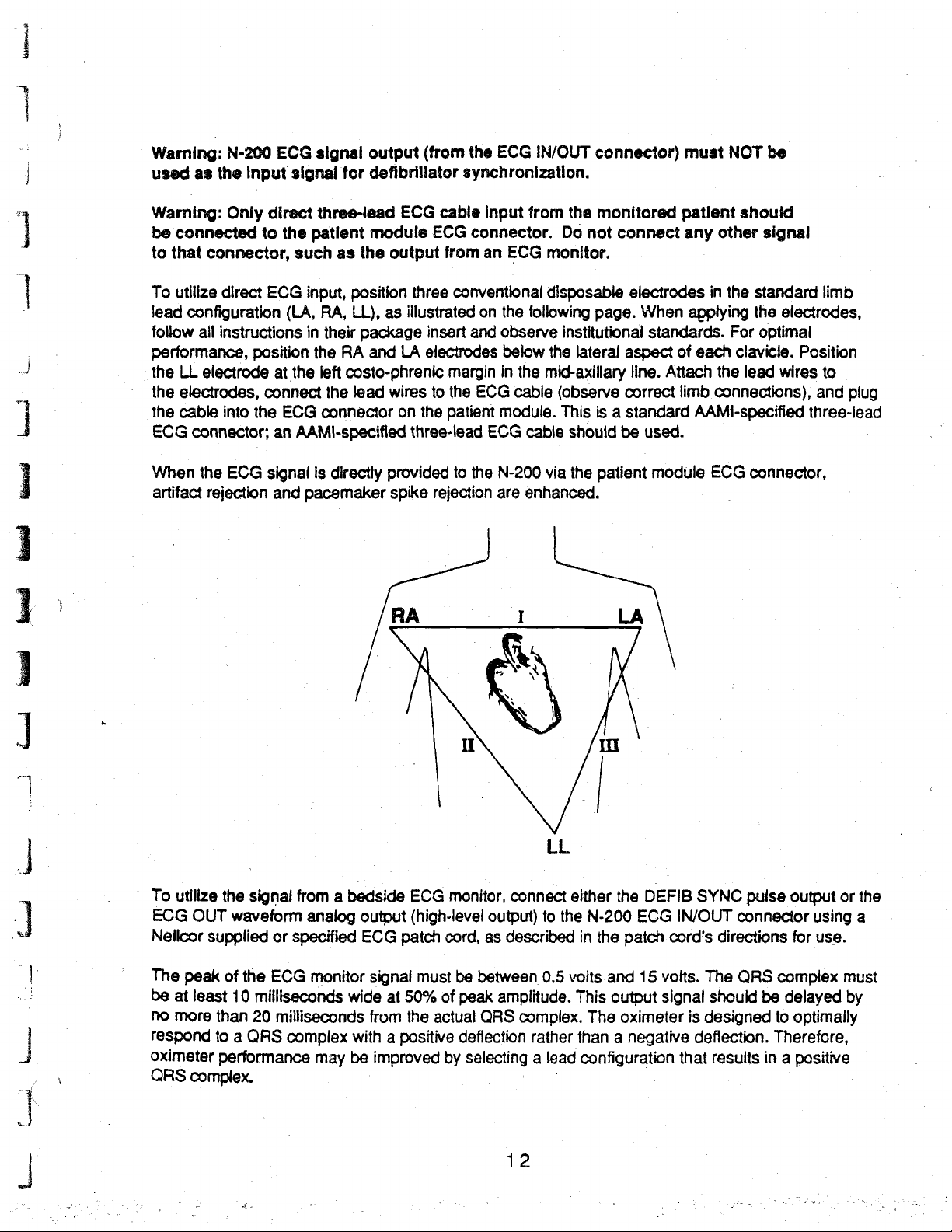
To
utilize
lead
follow
performance,
the
the
the
cable
k 4
ECG
When
artifact
N-200
as
the
Input
Only
direct
to
connector,
direct
ECG
configuration
all
instructions
position
LL
electrode
electrodes,
into
at
connect
the
connector;
the
ECG
signal
rejection
ECG
signal
signal
for
three-lead
the
patient
such
as
the
input,
position
(LA,
RA,
LL),
in
their
package
the
RA
the
left
costo-phrenic
the
lead
ECG
connector
an
AAMI-specified
is
directly
and
pacemaker
output
defibrillator
module
and
(from
ECG
cable
ECG
output
three
as
illustrated
insert
LA
electrodes
the
synchronization.
connector.
from
conventional
and
margin
wires
to
the
on
the
patient
three-lead
provided
spike
to
the
rejection
ECG
input
an
ECG
on
the
observe
below
in
ECG
module.
ECG
N-200
are
IN/OUT
from
the
Do
monitor.
disposable
following
institutional
the
lateral
the
mid-axillary
cable
(observe
This
cable
should
via
the
enhanced.
connector)
monitored
not
connect
electrodes
page.
When
standards.
aspect
line.
Attach
correct
is a standard
be
used.
patient
module
must
NOT
be
patient
any
applying
of
limb
should
other
signal
in
the
standard
the
For
optimal
each
clavicle.
the
lead
connections),
AAMI-specified
ECG
connector,
limb
electrodes,
Position
wires
to
and
plug
three-lead
.
E
ζωα
1
0000
1
To
utilize
ECG
OUT
Nellcor
The
be
no
peak
at
least
more
supplied
respond
oximeter
QRS
complex.
the
signal
from a bedside
waveform
or
specified
of
the
ECG
10
milliseconds
than
20
milliseconds
to a
QRS
complex
performance
analog
output
ECG
monitor
signal
wide
from
with a positive
may
be
ECG
(high-level
patch
must
at
50%
the
actual
improved
monitor,
cord,
be
of
peak
deflection
by
selecting a lead
connect
output)
as
described
between
amplitude.
QRS
complex.
to
0.5
rather
either
the
volts
N-200
in
the
This
The
the
DEFIB
ECG
patch
and
15
output
oximeter
than a negative
configuration
SYNC
IN/OUT
cord's
volts.
The
signal
should
is
designed
deflection.
that
results
pulse
output
connector
directions
QRS
for
complex
be
delayed
to
optimally
Therefore,
in a positive
or
using
use.
must
by
the
a
я
used
12
=
Page 22
Refer
the
signal
N-200
to
the
must
operator's
from
an
be
operating
ECG
manual
monitor,
on
AC
for
the
the
power.
ECG
N-200
monitor
powerbase
before
attempting
must
be
any
connected
connection.
to
the
monitor
When
and
using
the
Warning:
your
cord's
Before
at
your
during
problem,
1.
value
β
i
4
2.
Test
Before
ECG
monitor,
directions
clinical
institution,
the
For
test
conventional
ECG
cord
to
the
is
displayed
accurate
oxygen
Connect
iluminated.
to
ensure
of
the
use,
following
contact
each
configuration
instrument
output
to
connect
oximeter's
and
transducer
the
is
displayed
ail
instrument
appropriate
N-200
use,
confirm
and
test
for
use.
test
each
also
perform a continuity
test
procedures,
Nelicor's
and
patch
disposable
signal
must
the
appropriate
“ECG
on
the
ECG
that
its
“ECG
to
oxygen
and
transducer
by
functions
the
that
the
ECG
Technical
of
clinical
cord
ECG
have
IN/OUT”
monitor,
IN
that
same
the
oximeter
under
operation
ECG
monitor).
the
ECG
patch
patch
the
cord
as
patch
cord,
as
test
first
check
Service
ECG
function
electrodes
Department
monitor
on
yourself
in
characteristics
output
USE”
to
before
port
port.
Turn
and
verify
indicator
person,
the
NELLCOR
and
that
both
clinical
on
following
normal
cord
described
.
described
before
all
the
clinical
connections.
to
be
used
or
configuration
previously
on
the
ECG
both
instruments.
that
the
pulse
is
steadily
the
patient
the
“ECG
and
alarm
use
(see
connector
below
below.
at
1-800-NELLCOR.
another
use.
If
that
with
that
and
If
the
Should
the
person
described.)
monitor
(“ECG
Verify
rate
displayed
illuminated.
instructions
module,
IN
USE”
indicator
conditions
the
Operator’ s and
is
compatible
in
the
patch
problems
does
not
NELLCOR
as
follows.
will
be
used
Use
OUT”
that a normal
by
Next,
in
its
directions
and
verify
remains
(e.g.,
with
patch
cord
is
fabricated
arise
resolve
the
oximeter,
Position
clinically.
the
ECG
or
“DEFIB
(The
patch
SYNC”)
tracing
the
oximeter
is
apply a NELLCOR
for
use.
that a saturation
steadily
"ECG
leads
Service
off”
Manuals
q
on
owe
Е
ess
pes
e
жи
nné
「
Warning:
the
saturation.
without
connect
module.
Operation
locates
steadily.
measurements,
An
actual
C-LOCK
the
an
The
QRS
If
with
ECG
ECG
monitor
complex
this
is
ECG
patient
an
ECG
signal.
ECG
R-wave
as
described
output
may
observed,
that
prevent
disconnect
synchronization,
ECG
leads
Signal:
When
is
it
then
in
directly
The
locks
being
the
“Principles
is
delayed
the
oximeter
the.patch
by
from
more
cord
substitute a different
to
the
connector
yellow
onto
ECG
an
used
IN
USE
adequate
to
identify
of
Operation”
signal,
than
20
calculating and
and
use
ECG
on
the
NELLCOR
indicator
the
pulse
section
the
flashes
ECG
and
of
milliseconds
displaying
the
N-200
monitor,
or
patient
when
the
IN
USE
indicator
synchronize
this
manual.
the
from
N-200
lights
saturation
Page 23
Operating
Modes
Selecting
accurate
different
Mode 1 is
Clinical
Mode 2 uses a 2
useful
Mode 3 uses a 10
When
N-200
In
all
beat,
recent
Setting
operating
LOW
PULSE
an
measurements
averaging
the
situations
for
special
the
patient
for
Mode
three
operating
the
instrument
beat
replace
the
Operating
mode
RATE
buttons,
RATE
Operating
standard
3.
is
display.
Mode:
despite
time.
operating
in
which
to 3 second
studies
to
is
unavoidably
The
the
in
15
second
pulse
modes,
recalculates
data
from
Mode:
better
and
suited
turn the
The
differing
mode.
patient
averaging
which
an
averaging
active
rate
is
the
N-200
the
the
earliest
When
to
the
control
N-200
has
levels
It
uses a 5
is
relatively
time
and
extremely
time
and
C-LOCK
NOT
displayed
updates
saturation
beat,
the
N-200
specific
knob
clinical
to
three
operating
of
patient
to 7 second
inactive.
therefore
fast
response
and
consequently
ECG
when
the
measurements
and
pulse
and
new
is
turned
setting,
the
righi
modes,
activity.
averaging
is
more
is
desired
which
Each
operating
affected
(e.g.,
is
least
synchronization
the
instrument
with
every
rate
measurements:
averages
on,
until
it
is
set
press
the
are
determined
for
Mode
and
hold
desired
enable
time
and
by
patient
sleep
affected
is
not
is
operating
pulse
data
1.
the
number
it
mode
is
useful
motion.
studies).
by
patient
being
in
beat.
from
and
If
another
HIGH
appears
to
make
uses
a
in
most
It
is
motion.
used,
set
the
Mode
3.
At
each
the
most
displayed.
RATE
in
and
the
-
When
Trend
The
pulse
memory
the
and
N-200
rate
stores
N-200
has
data,
once a second.
operator
Data
.N-200
~
on
The
data
initiates
are
automatically
memories
battery
N-200
power.
adds
with a time
automatically
Trend
devices.
and
During
event
is
turned
Event
two
memories.
sampled
up
to
This
an
accumulate
Data
new
marker.
erased
data
output,
off
and
Memories
The
once a second
one
hour
of
event
sampling
“event.”
data
as
are
Both
acquired
data
are
retained
to
that
When a memory
new
data
available
the
N-200
back
trend
oxygen
is
memories
and
stored
even
in
the
which
are
stored.
in
both
monitor
on
again,
memory
and
averaged
saturation,
either
associated
also
unless
when
the
memories
is
already
has
been
analog
must
it
returns
stores
up
every
pulse
with
record
the
the
operator
powerbase
while
stored,
completely
and
digital
be
connected
to
Mode
to
12
five
rate,
and
an
alarm
time
of
has
is
detached
the
instrument
and
identifies
fi
filled,
formats
to
the
1.
hours
of
seconds.
pulse
state
data
acquisition.
disabled
the
the
oldest
for
output
powerbase.
oxygen
The
perfusion
and
is
beginning
saturation
higher
or
it
occurs
the
memories.
the
monitor
turned
data
to
printers
resolution
data,
when
-
off.
of
the
are
and
sampled
the
The
is
operating
new
or
other
event
14
Page 24
ii
HN
i
_]
]
1
Setting
~
ha
described
1.
2.
3.
|
4.
5.
6.
the
Clock:
below.
Year:
Simultaneously
OXYGEN
thebuttons
buttons.
Month:
the
month
Day:
existing
displayed.
Hour:
“military”
Minute:
Allow
LOW
SATURATION
in,
Press
existing
is
displayed.
Press
the
day
Then
Repeat
time
Repeat
at
least
SAT
and
month
Before
turn
the
the
same
setting.
Then
same
setting.
While
release
Step 2 to
(i.8.,
1:00
Step
five
seconds
HIGH
initially
press
display
control
buttons
While
release
buttons
holding
the
set
the
PM
3 to
set
to
RATE
storing
the
LOW
are
knob
until
again.
holding
the
again.
the
buttons.
hour
is
13:00
the
minutes
alapse,
buttons
data
SAT
and
the
last
the
The
the
buttons.
The
flashing
buttons
(OXYGEN
hours;
(PULSE
and
then
five
times.
in
the
memories,
HIGH
two
digits
correct
flashing
buttons
in,
year
number
in,
number
turn
SATURATION
midnight
is
RATE
check
RATE
of
the
is
displayed.
turn
in
the
control
00:00
display).
the
settings
set
the
internal
buttons.
The
existing
in
the
OXYGEN
the
control
the
PULSE
knob
display).
hours).
by
simultaneously
flashing
year
Then
knob
RATE
until
The
clock,
as
numbers
setting.
release
the
While
the
SATURATION
until
the
display
correct
clock
uses
in
holding
display
correct
is
the
day
is
24-hour
pressing
.
the
is
the
i
"|
_
The
N-200
elapse
starts
Trends:
average
trend
.
Printing T Trend
ThinkJet™
chart
be
are
described
Using a ThinkJet
SERIAL
Instruments.”
Only,”
to
=
sequentially
between
the
sequence
The
of
memory.
recorder,
oxygen
the
printer
any
sampled
Up
connected.to
being
printed.
at
the
COMM
To
as
described
begin
printing.
sets
of
the
again
(beginning
saturation
values
to
12
hours
Data:
Data i in
with
an
as
described
AC
power.
The
data
end
of
this
Printer:
connector
print
only
in
the
the
year,
steps
and
is
of
RS-232
below.
The
are
section.
Set
according
trend
same
month,
listed
above,
with
pulse
computed
these
data
the
trend
serial
To
instrument
retained
up
the
printer
to
data,
set
section.
day,
then
“year”.
rate
measurements
every
can
be
memory
interface
print
the
continues
in
memory
and
the
instructions
the
N-200
Then
press
hour,
and
the
existing
five
seconds.
stored.
may
be
(model
contents
to
after
connect
RS-232
the
minute.
changes
are
sampled
That
printed
2225D)
of
on a Hewlett-Packard
the
trend
function
printing,
it
to
the
in
“Connecting
FORMAT
TREND
If
more
than
are
stored
every
average
or
on
is
an
analog
memory,
then
as a monitor
unless
N-200
the
they
are
rear-panel
N-200
switches
button
on
the
five
seconds
and
second
stored
strip-
the
N-200
while
erased,
to
to
“Graphics
back
the
and
|
the
trend
Other
of
the
N-200
the
in
the
must
as
N-200
data
fis
de
15
Page 25
ee
|
: 1
|
When
trend
8-1/2" x 11"
printout
the
range
0.
The
pulse
if
the
data
The
following
data
are
page,
with
represents
of
the
data:
rate
scale
are
suited
automatic
printed
the
50
seconds.
the
is 0 to
to
it.
markers
on a ThinkJet
earliest
maximum
Time
data
The
250
beats
(date,
appear
value
in
the
oxygen
is
per
hour,
on
printer,
minute)
ThinkJet
12
hours
top
left
portion
saturation
always
minute; a narrower
scale
100%:
is
presented
trend
of
data
are
of
the
page.
is
automatically
the
minimum
range
along
graphs:
printed
is
automatically
the
on
Each
point
selected,
value
is
horizontal
50%,
one
on
axis.
the
based
25%,
selected
on
or
.
Whenever
minutes
the
signal
consists
occurrence
3:47
AM).
on
the
occurrence.
type
of
the
horizontal
printer.
Using
as
described
the
settings
graphics
by
the
-
on
the
an
“A”
elapse,
was
no
lost
of a tick
and
the
lf
more
horizontal
if
more
event
and
axis.
an
Analog
in
“Connecting
as
necessary,
printer,
graphics
N-9000
printer
recorder/interface.
Alarm-limit
User-defined
Power
Pulse
“Clock
Signal
marker
mark
than
axis,
time
Strip-Chart
that
appears,
“A”
marker
is
represented
on
the
time
of
six
markers
but
than
60
of
occurrence.
The
example
printer
rather
Occurrence
event
event
turned
signal
is
is
is
horizontal
onset
only
the
events
Recorder:
the
and
confirm
must
than
off
is
lost
reset
acquired
the
trend
printed;
on
the
(e.g.,
“L3:47"
occur
first
six
are
stored
The
on
the
N-200
to
proper
be
turned
the
strip-chart
instead
trend
axis,
in
next
graph
the
graph
along
indicates
close
succession,
are
identified
in
memory,
remaining
page
Connect
Other
Instruments.”
operation.
off.
Otherwise,
recorder.
Marker
(^
01
ends
and a new
period
by
with
events
illustrates
the
during
missing
the
letter
an
alarm-limit
each
by
type
only
are
the
strip-char
Calibrate
If
the
the
Do
not
70
00
<)
>
one
begins.
which
data
points.)
that
indicates
event
is
identified
of
event
the
last
60
identified
trend
output
recorder
the
N-200
trend
is
memory
attempt
(If
less
the
power
Each
marker
the
type
that
began
by a tick
and
time
of
will
be
identified
only
by
tick
from a ThinkJet
to
the
N-200,
recorder,
also
connected
will
be
to
print
trend
than
was
off
of
at
mark
marks
adjust
to
printed
data
five
or
by
on
a
To
print
the
trend
approximately
strip-chart
identified
The
push
the
point
at
the
recorder
by
zero-voltage
trend
output
the
TREND
at
which
beginning.
memory,
one
can
button
it
hour
was
be
was
press
of
data
per
printing
outputs.
stopped
again
stopped;
the
TREND
minute.
real-time
at
any
time
less
than
if
more
than
button.
If,
prior
data,
by
30
30
16
Data
to
printing
the
beginning
again
pressing
seconds
seconds
|
are
have
have
printed
the
and
the
at
trend
end
TREND
elapsed,
elapsed,
the
memory,
of
the
button.
the
output
the
rate
of
the
trend
output
data
are
To
restart
continues
starts
again
it,
from
Page 26
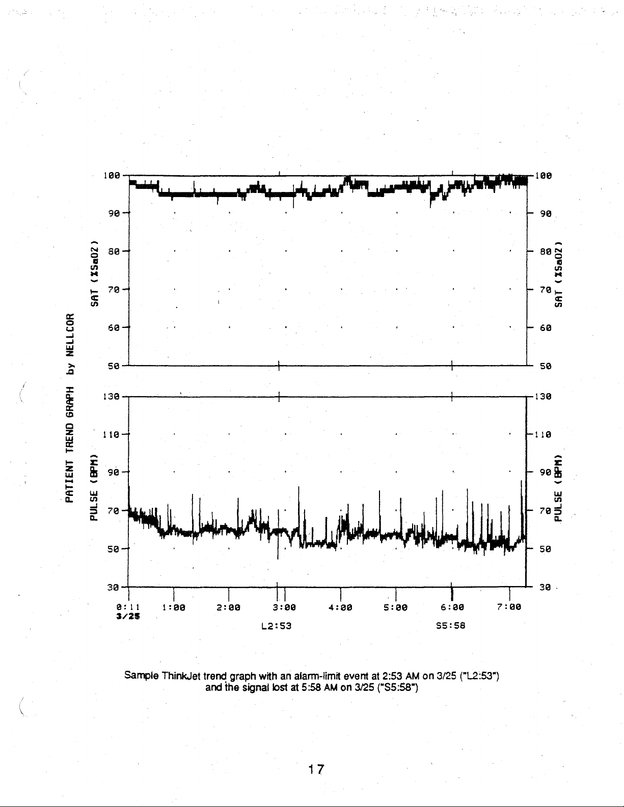
199
|
98
—
88
— -
(XSa07)
704
SAT
1
1
A
|
1
|
n“
—
—
98
BON
70,
n
~
トコ
n
ο
6a-
NELLCOR
by
sa
139
GRAPH
110
TREND
|
98
(BPM)
PATIENT
78
PULSE
50
o
8:11
3/25
-
— -
|
:B8
2:88
E
+
]
3:90
L2:53
|
4:88
7
5:00
+
4
|
6:98
$5:58
-118
-
ト - 58
por:
7:90
60
5ο
136
9%
785
r
u
n
a
Sample
ThinkJet
trend
and
graph
the
with
signal
lost
an
alarm-limit
at
5:58
17
AM
event
on
3/25
at
2:53
AM
("S5:58")
on
3/25
{"L2:53")
Page 27
The
Er
following
recorder:
automatic
markers
appear
on
the
一
trend
graphs
printed
by an
analog
strip-chart
If
more
Events:
perfusion
in a data
stored.
There
moves
For
an
"
30
seconds
before
Beginning
End
of
the
Time
when
Time
when
Time
when
Alarm-limit
than
60
events
The
event
measurements.
display
are
two
beyond
alarm-limit
the
types
the
after
event
that
is
of
the
trend
trend
output
the
signal
the
pulse
the
N-200
or
user-defined
are
memory
During
has
higher
of
events:
established
event,
the
end
the
of
initiated
output
|
is
acquired
signal
is
lost
is
turned
off
event
stored
in
memory,
stores a “snapshot”
the
snapshot,
resolution
alarm-limit
limits,
snapshot
the
alarm
and
lasts
than
events
and
user-defined
starts
state.
For a user-defined
from
one
A
one-second,
À
two-second,
ㆍ
A
full-scale
A
full-scale
A
full-scaie
A
full-scale
only
the
of
concurrent
measurements
the
trend
which
30
seconds
to
60-minutes
by
two
last
60
memory.
occur
events
before
zero-voltage
full-scale
zero-voltage
to
current-value
to
current-vaiue
to
current-value
to
zero-voltage
will
be
identified.
oxygen
are
each
which
event,
(the
saturation,
obtained
Up
to
time
the
the
beginning
the
operator
output
deflections
output
deflection
deflection
deflection
deflection
pulse
once
every
one
hour
of
:
the
saturation
operator
snapshot
selects
initiates.
of
the
alarm
starts
the
followed
rate,
and
second,
event
data
or
pulse
rate
state
30
seconds
duration).
pulse
resulting
may
be
and
ends
ㆍ
Printing
RS-232
contents
function
printing,
Event
serial
of
the
as a monitor
unless
Using a ThinkJet
COMM
To
in
To
The
When
the
identifies
mark
(e.g.,
each
connector
print
only
“Connecting
print
all
events
events
page.
are
event
The
the
on
the
“E15:10"
event.
Data:
Data
in
the
event
interface
event
they
event
the
printed
data
graph
type
horizontal
(model
memory,
while
are
erased
Printer:
according
data,
set
N-200
that
are
of
to
are
when
output
begins
event
axis,
2225D)
the
the
event
as
Set
up
the
to
the
the
N-200
Other
Instruments.”
stored
(alarm
in
the
button
on a ThinkJet
30
seconds
limit
along
with a letter
identifies a user-defined
The
oxygen
saturation
memory
or a strip-chart
N-200
must
be
data
are
being
described
instructions
at
printer
and
RS-232
memory,
(L]
press
is
released.
printer,
before
or
user-defined
that
event
that
scale
is
automatically
18
may
be
recorder,
operating
printed.
the
end
connect
in
“Connecting
FORMAT
the
EVENT
the
earliest
the
beginning
indicates
began
printed
as
on
AC
The
of
this
section.
it
to
the
the
switches
button
data
of
[E]}.
Each
the
at
3:10
selected,
on a ThinkJet
described
power.
data
are
N-200
N-200
to
“Graphics
are
each
event,
marker
type
of
PM).
New
based
on
below.
The
retained
rear-panel
to
Other
the
back
in
the
top
and
consists
event
and
scales
on
the
printer
N-200
in
with
To
print
continues
memory
SERIAL
Instruments.”
Only,”
as
of
the
left
portion
an
automatic
of a tick
the
time
are
printed
range
of
an
the
to
after
described
N-200.
of
marker
of
onset
for
the
data:
Page 28
4
<
r
Wii
>
des
the
maximum
selected
output
To
“no
of
After
pressing
desired
EVENT
and
to
a
on a ThinkJet
determine
E"
is
stored
determining
then
be
printed.)
letter
that
value
based
on
the
displayed
events
the
LOW
event
appears
button.
The
turning
The
indicates
is
always
the
range
printer.
number
if
no
events
(up
to
60
the
number
SAT
and
in
event
the
control
identifiers
the
100%;
of
the
of
events
are
events).
of
LOW
the
display.
is
then
knob
for
type
of
the
minimum
measurements.
in
memory,
stored
If
more
events, a specific
RATE
buttons,
Then
printed.
until
the
events
event,
are
and
press
in
memory,
than
60
turn
release
(Also,
pressing
identifier
the
same
the
hour
value
The
and
or
events
event
the
the
buttons
for
the
as
and
is
50%,
example
hold
“nnn
E”
are
stored,
may
be
control
the
EVENT
desired
those
minute
25%,
on
the
the
LOW
is
dispjayed
only
printed
knob
and
within
button
event
printed
at
which
or
0.
next
SAT
the
as
until
10
appears
on
the
the
The
pulse
page
illustrates
and
LOW
to
indicate
last
60
follows.
the
identifier
seconds
for
at
least
causes
ThinkJet
event
rate
scale
RATE
the
number
are
available.
While
still
for
the
press
three
that
output:
started.
is
event
buttons.
the
seconds
event
Le
be.
оо
{
19
Page 29
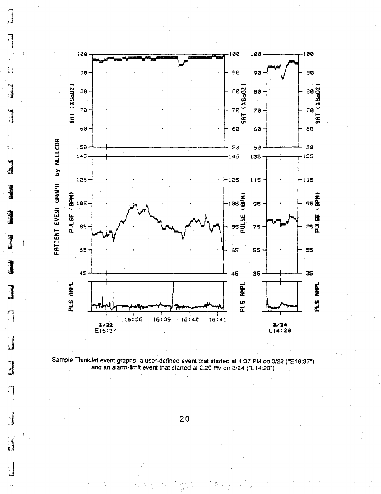
100-
100 | 198—
199
|
|
od
i
]
1
-
,
4
т:
|
S
回
Y
ve
=
고
σα
n
α
©
ы
a 145
=
>
pei
|
È
r r
2
Bios,
Gow
Z à
JB
=
8
=
—
£
99-4
804
7a
60
59 一 一
1254
θ5-
65
-
ἳ
ㆍ
.
一
|
.
"ーー
o
. .
'
=
-
'
‘+930
+
808
--
7927
・ ト eg
50 50
145
“R125
ask
q
gi
δα
be
=
un
90-44.
se
7e-
604
135
1154
95-
i
E
-
855
754
а.
m
-
65
SS
1
+
:
・
IVA
一
-
99
-
8
+
79
-
60
59
135
-115
|
95%
„A
=
755.
55
(35602)
501
r
Ls
ᾱ-
]
“|
:
、
BE
>
à
[20000
<
2
Sample
45
WM
ThinkJet
|
ra
T
.
3/22
E16:37
event
and
an
alarm-limit
T
16:38
graphs:
a
lr
T T
16:39.
,
user-defined
event
that
started
16:48
event
at
20
that
2:20
45
7
16:41
started
PM
on
at
3/24
E
a
3
4:37
(Lia:
35
|
PM
+
ne
TT
3/24
‘Li4:28
on
3/22
("E
20")
35
E
a
2
16:37")
Page 30
Using
described
settings
N-200,
rather
To
minutes
an
it
than
print
as
the
of
channel.
appear
on
Analog
in
“Connecting
necessary,
must
be
by
the e sirip-
event
data
are
The
earliest
the
event
Strip-Chart
the
and
confirm
turned
memory,
off.
-chart
printed
event
graphs
press
each
and
printed
Recorder:
N-200
Otherwise,
recorder.
to
proper
the
EVENT
minute.
earliest
by
Connect
Other
Instruments.”
operation.
the
event
button
Events
data
are
an
analog
the
strip-chart
Calibrate
If a graphics
data
will
be
on
the
are
separated
presented
strip-chart
recorder
the
recorder,
printer
printed
back
by a zero-voltage
first.
recorder:
by
of
the
The
following
the
N-200.
to
the
N-200,
adjust
is
also
attached
graphics
Approximately
output
automatic
as
the
to
printer
on
each
markers
the
10
Occurrence
Beginning
30
of
Beginning
End
Time
Time
Time
The
event
output
push
the
EVENT
point
at
which
beginning.
Do
not
attempt
-
Initiating a User-Defined
HIGH
RATE
the
“0”
is
buttons.
released.
of
seconds
the
event)
of
of
the
event
when
the
when
the
when
the
can
button
it
was
While
the
to
print
and
replaced
The
data
the
the
stopped;
event
AUDIO
stored
event
before
event
is
acquired
signal
pulse
signal
N-200
be
stopped
again—if
output
event
ALARM
by
the
output
the
beginning
is
acquired
is
is
turned
at
less
if
more
is
data
on the
Event:
desired
in
the
event
(which
lost
any
stopped,
OFF
event
is
off
time
than
30
than
30
N-9000
To
initiate a user-defined
buttons
duration
memory
|
|
by
again
pressing
seconds
seconds
there
is a zero-voltage
recorder/interface.
(“UdE
(1
to
begin
A
one-second,
|
A
A
A
A
A
have
have
elapsed,
0”
appears).
60
minutes).
30
Seconds
by
one
full-scale
one-second,
full-scale
two-second,
full-scale
full-scale
full-scale
elapsed,
event,
the
to
to
to
to
EVENT
the
the
output
press
Turn
Then
before
Marker
zero-voltage
deflection
zero-voltage
zero-voltage
zero-voltage
current-value
current-value
current-value
button.
output
output
signal.
and
the
control
release
the
buttons
output
deflection
output
deflection
deflection
deflection
To
restart
continues
starts
again
hold
the
knob
the
are
followed
and
another
output
the
from
at
the
until
output,
the
To
change
.
AUDIO
that
appears.
To
OFF
buttons.
*
Setting
alarm
memory
ALARM
remain
Then
end a user-defined
buttons,
the
limits
whenever
the
duration
OFF
in
the
ongoing
release
and
turn
Limits
determine
that
the
of
an
ongoing
buttons.
the
event
the
“Ude
event.
buttons.
prematurely,
control
Trigger
when
an
saturation
user-defined
n”
appears,
Turn
the
control
press
knob
to
the
an
Alarm-Limit
alarm-limit
or
pulse
event
rate
21
with
knob
and
left
until
Event:
occurs
falls
event,
press
“n”
representing
until
the
hold
the
“UdE
OFF”
Normally,
(i.e.,
outside
the
and
desired
HIGH
data
alarm
hold
the
the
number
number
RATE
appears.
the
established
are
stored
limits).
and
Then
in
HIGH
of
of
AUDIO
release
the
RATE
minutes
minutes
ALARM
the
event
and
-
Page 31

N
To
set
power.
and
the
desired
from
50%
per
beats
To
again
power,
the
contro!
event
limits
Press
the
rear-panel
setting
press
appears
to
100%,
minute.
make
an
the
knob
that
differ
applicable
EVENT
in
and
the
event
limit
applicable
to
the
right
from
alarm
button:
the
display.
pulse
equal
alarm
until
“=
the
alarm
button
while
The
rate
event
to
the
button
AL”
limits,
(HIGH
holding
saturation
limits
alarm
and
the
appears
the-N-200
SAT,
LOW
them
in,
event
may
limit,
while
EVENT
in
the
display.
SAT,
turn
limits
be
set
the
button:
must
the
for
N-200
be
operating
HIGH
control
may
be
any
value
is
while
holding
on
RATE,
knob
operating
set
from
or
until
for
them
AC
LOW
any
35
on
the
value
to
AC
in,
RATE)
250
turn
When
alarm-limit
Canceling
press
both
control
“Prt
To
knob
Erasing
HIGH
control
time
To
control
Disabling
HIGH
active.
appears.
knob
knob
End"
avoid
to
the
the
SAT
knob
the
contents
preserve
knob
SAT,
To
until a flashing
the
N-200
values.
Trend
the
lights
or
TREND
to
the
steadily
canceling
left
until
Trend
and
HIGH
to
the
of
the
data
to
the
the
Trend
HIGH
RATE,
disable
If
the
them,
memories
is
Event
and
right
until
and
the
output
“Prt"
and
Event
RATE
right
until
both
after
left
until
and
while
“t E On”
turned
off
Output:
EVENT
“Prt
End”
the
output
after
appears.
Memories:
buttons
“ALL
memories
starting
“not
cir”
Event
and
Memories:
AUDIO
holding
are
disabled,
appears.
and
back
To
stop
buttons
flashes.
is
canceled.
starting
(“CLr t E”
cir’
appears
will
be
to
erase
appears.
ALARM
the
buttons
to
reactivate
on
again,
an
ongoing
(“End
Prt"
Then
to
do
so,
To
erase
appears
in
the
erased.
the
memories,
Then
To
disable
OFF
in,
the
avent
output
appears);
release
before
the
release
buttons.
tum
them
releasing
stored
in
the
display.
while
the
both
“t E On”
the
hold
limits
of
the
trend
while
holding
the
buttons,
the
trend
and
display);
Then
release
still
hoiding
while
buttons.
memories,
is
displayed
control
the
knob
buttons
are
reset
to
the
or
event
them
in,
at
which
buttons
event
the
the
simultaneously
time
turn.the
data,
holding
buttons,
buttons
if
the
them
untii a flashing
in
and
tum
memories,
turn
the
control
press
the
in,
turn the
at
which
in,
turn
press
memories
“t E diS”
the
control
the
the
are
When
described.
the
memories
When
the
are
disabled,
N-200
is
turned
the
operator
off
and
can
back
still
trigger a user-defined
on
again,
the
memories
22
event,
are
made
as
previously
active
again.
Page 32

Powerbase
The
powerbase
isolated
powerbase
The
waveform,
fiber
N-8000
power
contains
powerbase
and a digital
optic
output
interface
is
the
for
operating
the
provides
connector
via
the
detachable
the
circuitry
analog
output
for
fiber
optic
connector
use
AC
power
monitor
required
outputs
with
cable.
supply
and
for
to
communicate
of
pulse
(RS-232
the
NELLCOR
and
external
recharging
with
waveform,
serial
interface).
N-9000
the
internal
the
oxygen
recorder/
interface
batteries.
monitor.
saturation,
In
addition,
interface
for
the
and
it
N-200.
In
addition,
pulse
also
provides
or
the
It
provides
the
rate
data,
a
NELLCOR
ECG
Because
bi-directional
Saturation,
the
transmitted
the
pulse
powerbase
from
Disconnecting
powerbase
the
latches
fiber
_
the
powerbase
To
reconnect
powerbase
the
monitor
Battery
If
external
„up
to
BATT
until
the
instrument
for
on
optic
outputs,
is
engage.
Operation/Portable
power
two
hours.
indicator
device
reliably.
N-200
optical
is
rate,
where
the
the
Powerbase
portable
each
side
and
is
detached
the
units,
aligned
is
lost
The
flashes
is
plugged
At
patient
link
pulse
they
that
is
waveform,
are
isolated,
powerbase
use.
To
of
the
ECG/defib
from
piace
them
with
the
rib
or
disconnected,
yellow
when
BATT
only
into
that
time
the
established
and
transiated
to
the
from
do
so,
monitor,
sync
the
on
into
monitor
the
place
which
inputs
monitor.
on a flat,
the
monitor.
Use
an
IN
USE
about
five
an
AC
power
an
internal
monitor
whenever
ECG
analog
to
and
waveform
initiate
Monitor:
the
instrument
allows
(from
stable
surface,
Push
internal
light
illuminates
minutes
source
switch
automatically
powerbase
the
monitor
or
digital
output
The
monitor
on a secure
the
units
the
external
and
the
powerbase
battery
of
or
automatically
to
battery
the
battery
communicate
and
data
are
outputs.
of
the
can
to
be
monitor)
position
indicate
power
level
turns
powerbase
transmitted
Status
trend
and
be
disconnected
flat
surface
separated.
are
not
them
straight
operates
battery
operation.
remain.
is
too
low
off
the
N-200.
through
are
connected.
from
the
information
event
memories.
from
and
firmiy
The
analog,
available
so
that
the
in
until
the
the
N-200
The
It
continues
to
power
a
monitor
is
the
push
digital,
when
groove
latches
for
red
to
flash
the
to
and
on
on
LOW.
the
|
©
The
battery
required
lf
C-LOCK
ECG
signal
to
signal
from
recharges
fully
recharge
ECG
synchronization
must
be
a
bedside
whenever
it.
supplied
ECG
monitor
the
instrument
is
used
directly
from
cannot
when
the
be
is
plugged
the
N-200
patient
through a cable
used.
23
into
AC
|
is
operating
power.
on
battery
attached
Fourteen
power,
to
the
hours
are
the
patient
module.
A
|
Page 33

x
fén
Warnings
ih
]
Carefully
In
the
temporarily
Tissue
the
sensor
instructions
specifications.
The
input
Only
the
j
as
the
patient
Loss
・
the
ㆍ
there
・
the
intravascular
*
the
hypothermia,
É
Inaccurate
ㆍ
incorrect
ㆍ
significant
methemoglobin;
・
significant
*
exposure
xenon
direct
・
excessive
・
venous
ㆍ
electrosurgical
*
placement
catheter,
Refer
complete
read
event
damage
sensor
site).
N-200
signal
direct
output
of
pulse
sensor
is
sensor
patient
light
sunlight;
to
the
information
this
operator's
of
an
adverse
silenced
too
tightly,
Refer
on
ECG
for
three-lead
module
from
signal
is
excessive
is
or
disabled.
can
be
caused
applying
to
the
application
signal
output
defibrillator
ECG
ECG
connector.
an
ECG
can
too
tight;
illumination
placed
line;
on
experiences
arterial
occlusion
measurements
application
levels
levels
to
excessive
source;
patient
or
of
dysfunctional
of
indocyanine
billrubin
|
movement;
pulsations;
interference;
of
the
sensor
or
intravascular
“Troubleshooting
and
manual
patient
by
before
condition,
incorrect
supplemental
directions
and
(from
use,
the
for
and
synchronization.
cable
input
from
Do
monitor.
occur
if
an
extremity
shock,
may
be
use
of a sensor;
(e.g., a surgical
hypotension,
proximal
caused
hemoglobins,
green,
illumination,
lamps; f fluorescent
on
an
line.
Guide”
suggested
such
extremity
in
actions.
attempting
the
audio
application
tape,
use
provided
for
description,
ECG
IN/OUT
the
monitored
not
connect
or
with a blood
severe
to
the
sensor,
by
methylene
as
surgical
that
has a blood
this
manual
clinical
alarm
or
failing
with
each
use
will
not
use
of a sensor
to
periodically
sensor
warnings,
connector)
must
patient
any
other
signal
bilirubin
pressure
lamp
cuff,
vasoconstriction,
or
cardlac
such
as
carboxyhemogiobin
biue
or
other
lamps,
lights;
especially
infrared
pressure
and
the
sensor
of
the
N-200.
sound
if
it
has
(e.g.,
wrapping
inspect
for
specific
cautions,
NOT
should
to
or
direct
arterial
and
be
used
be
connected
that
connector,
sunlight);
catheter,
severe
arrest.
intravascular
ones
heating
directions
lamps;
cuff,
arterial
for
been
the
as
the
or
anemia,
or
dyes;
with
a
or
use
to
such
—
for
Do
not
use a damaged
sensor;
do
Explosion
not
irradlate
hazard.
Do
sensor
it;
and
not
use
or
one
do
the
with
not
steam
N-200
exposed
autoclave
In
the
24
electrical
it.
presence
contacts;
of
flammable
do
not
immerse
:
anesthetics.
a
Page 34

ELI
Vold
Warning:
produced
improper
Warning:
improper
manual
Nellcor
patients
(<3
Nellcor's
its
reusable
'
maintain
sterile
Among
transducer,
oxygen
pediatric
provides a family
kg),
optical
adhesive
the
transducer,
OXISENSOR
Use
only
by
other
oximeter
Incorrect
operation
and
the
directions
of
various
infants
DURASENSOR®
components
sensor.
sizes.
(3-15
An
appropriate
sensors;
available
the
OX/BAND
the
digit
oxygen
N-25
neonatal
11.
NELLCOR
manufacturers
performance.
application
of
the
of
Specific
kg),
are
OX/BAND
positioning
their
NELLCOR
OX/SENSOR
transducer,
oxygen
or
N-200.
for
use
sensors
NELLCOA
children
oxygen
mounted
and
disposable
of
optical
sensors
OXI-200N
the
oxygen
transducer
the
NELLCOR
transducers.
with
NELLCOR
use
of a sensor
Carefully
provided
that
small
in a plastic
optical
components
neonatal
R-15
OX/SENSOR
transducer.
read
with
are
suitable
sensors
adults
is a reusable
adhesive
components.
are
the
oxygen
adult
SENSORS
Use
pulse
may
the
“Warnings”
the
sensor.
for a variety
have
(15-50
casing.
DURASENSOR
nasal
The
wrap
are
mounted
transducer,
oxygen
|-20
infant
of
oxygen
oximeters
cause
kg),
is
tissue
of
been
developed
and
sensor
OXIBAND™
used
to
clinical
adults
supplied
OX/SENSOR™
in
medical-grade
DS-100A
the
transducer,
digit
oxygen
transducers
may
result
damage
section
settings
for
(>40
in a nonsterile
oxygen
apply
it
to
oxygen
adult
OX/SENSOA
the
transducer,
in
or
of
this
-
and
use
on
kg).
transducer
the
patient
transducers
adhesive
digit
D-25
OXISENSOR
for
neonates
package;
and.
tape.
oxygen
adult
and
the
is
a
D-20
are
digit
Each
sensor
To
select
are
whether
To
ensure
for
use,
cautions
If
excessive
may
lights,
heating
If
poor
xg,
its
measurements
ethmoid
If
patient
*
check
*
use
the
available,
sterility
keep
noted
result
especially
lamps;
patient
consider
artery,
movement
whether
C-LOCK
is
designed
appropriate
as
well
is
required,
optimal
in
performance,
the
sensor
in
the
ambient
inaccurate
those
and
perfusion
using
the
from
this
the
ECG
for
application
sensor,
as
the
site
sensor
light
is
measurements.
with a xenon
direct
sunlight.
is
affecting
OXISENSOR
an
artery
sensor
is
presenting a problem,
sensor
consider
adequacy
and
the
use
at
the
level
directions
present,
supplied
can
obtain
is
securely
anticipated
an
cover
light
instrument
R-15
synchronization;
to a specific
the
patients
of
the
patient's
duration
appropriate
of
the
for
use.
the
Light
source;
adult
by
the
sensor,
patient's
sensor
sources
bilirubin
performance
nasal
internal
measurements
evaluate
and
property
site(s)
on
weight
perfusion,
of
monitoring.
apply
heart,
site
with
that
can
lamps;
and
oxygen
carotid,
when
peripheral
the
following
applied;
patients
and
and
opaque
affect
transducer.
within a certain
which
the
it
observe
fluorescent
the
sensor
level
of
as
described
material.
performance
patient
Because
the
nasal
perfusion
possible
application
patient
all
lights;
weighs
activity,
in
the
warnings
Failure
include
infrared
more
the
septal
anterior
is
relatively
solutions:
size
range.
sites
directions
and
to
do
so
surgical
than
50
R-15
obtains
poor.
25
Page 35

mm
r
W.
use a new
move
the
use a type
1-20;
set
the
N-200
sensor
sensor
of
sensor
for
with
fresh
to a less
that
tolerates
Mode
3.
adhesive
active
site;
some
backing;
patient
motion,
such
as
the
D-25,
D-20,
N-25,
or
Finally,
should
such
move
move
plug
N-200
move
check
although
interference
the
the
the
N-200
on
the
whether
if a NELLCOR
sensor
if
directly
appropriate,
electrosurgical
When
cause
adequate
functioning.
using
the
N-200
ECG
C-LOCK
the
N-200
cables
ground
battery
sensor
of
pad
and
power;
as
the
sensor
sensor
to
the
use
an
interference.
ECG
to
begin
signal
is
is
designed
ever
present a problem,
the
N-200
closer
the
electrocautery
far
away
is
and
to
from
dry
the
extension
patient
module;
OX/SENSOR
|
synchronization,
using
the
again
available,
to
minimize
the
electrocautery
surgical
unit
the
electrocautery
and
firmly
cable
is
D-25
optical
signal
C-LOCK
any
evaluate
site;
into
different
attached;
being
used,
oxygen
an
transducer,
electrocautery
alone
for
ECG
synchronization
effects
the
following
unit
as
AC
circuits
site
and
remove
unit
obtaining
of
electrosurgical
possible
far
apart
as
possible;
or
consider
ground
the
which
pad
extension
has
added
may
disrupt
measurements.
automatically
interference,
solutions:
operating
as
possible;
cable
and
insulation
the
ECG
When
begins
the
connect
against
signal
and
an
the
3
を
一
-一
ik
ἕ
26
i
Page 36

The
NELLCOR
enhance
NELLCOR
IV.
and
N-8000
CONNECTING
N-200
expand
pulse
its
capabilities.
interface,
oximeter
other
analog
THE
may
These
N-200
be
connected
include
recorders,
the
TO
OTHER
to a variety
NELLCOR
and
digital
of
N-9000
devices
INSTRUMENTS
other
instruments
recorder/interface,
including
printers.
that
the
Caution:
proper
device
When
connected
record
strip
Connect
1.
2.
3.
of
chart,
Set
switch 8 up).
Set
Connect
the
powerbase.
connector
transmission
When
operation
for
complete
oxygen
and
all
the
N-9000
the
N-200
the
N-200
the
in
connecting
before
clinical
instructions.
Connecting
to
the
N-200,
saturation,
recordings.
to
the
baud
rate
RS-232
gray
Connect
until
may
end
it
snaps
occur
format
of
the
the
pulse
include
N-200
to
2400
the
fiber
the
into
if
the
NELLCOR
use.
the
NELLCOR
rate,
timing
as
follows.
using
to
the
optic
biue
end
place.
cable
N-200
Refer
to
NELLCOR
N-9000
and
pulse
marks.
the
BAUD
N-9000
cable
to
the
Route
the
is
kinked.
to
any
the
Instrument
N-9000
recorder/
waveform
RATE
Recorder
provided
N-9000
fiber
optic
other
|
Recorder/Interface
interface
data.
switches
format
with
connector
(DIP
the
cable
instrument,
manual
The
N-9000
labeled
for
provides
readings
(DIP
switches
without
switch 7 down,
to
DATA
bends;
verify
the
are
3-5
the
other
-
an
ongoing
printed
down).
DATA
INPUT.
poor
ona
DIP
connector
Push
each
on
The
N-200
and
digital-output
A
general-purpose
record
event
©
The
voltage
of
memories.
N-200
range
VOLTAGE
50%
to
100%
may
oxygen
analog
required
switch.
display
also
be
connected
connectors.
strip-chart
saturation,
output
The
connectors
by
the
oxygen
using
to
the
Refer
to
the
Connecting
recorder
pulse
recorder
saturation
the
N-200
may
rate,
are
(0
Sa02%
pulse
NELLCOR
N-8000
Other
be
connected
waveform,
standard
to 1 volt
output
can
SCALE
27
N-8000
operator's
interface
manual
u
Strip-Chart
to
the
N-200
ECG
data,
3/32"
subminiature
or 0 to
10
be
set
switch.
volts)
for a 0
to
provide
for
full
instructions.
Recorders
to
provide a permanent
and/or
is
to
phone
set
with
100%
data
plugs.
the
display
additional
in
the
The
N-200
or
analog
trend
output
an
expanded
and
Page 37

--
To
print
buttons
oxygen
to
generate
saturation and
zero
and
heart
rate,
full-scale
voltage
use
the
SAT
signals
and
in
order
RATE
to
connectors.
adjust
the
recorder
Use
the
ZERO
controls.
and
FULL
|
W
.
。
To
print
the
waveform,
full-scale
To
use
Note:
Improper
voltage.
The
contents
perfusion,
The
Service
It
may
voltage
print
trend
the
SAT,
Connect
loading
ThinkJet
of
ThinkJet
Department.
be
connected
pulse
use
the
data
RATE,
only a high
printer
the
trend
and
monitor
printer
(plethysmoqraphic)
ECG
IN/OUT
signals
at
on a strip-chart
and
PULSE
distorts
the
connector.
the
PULSE
recorder,
connectors.
impedance
correspondence
Connecting
with
an
RS-232
and
event
memories,
status.
and
necessary
to
the
N-200
as
waveform,
connector
device
the
Hewlett-Packard
serial
accessories
use
Use
the
in
use
the
(1 M ohm
between
interface
as
well
as
may
follows.
the
PULSE
ZERO
order
SAT
and
or
the
(model
to
record
be
ordered
ーー
connector:
and
FULL
to
adjust
RATE
higher)
measured
ThinkJet
22250)
ongoing
directly
to
buttons
the
recorder
connectors;
to
the
analog
voltage
Printer
may
be
used
saturation,
from
print
theECG
to
generate
controls.
to
print
output
and
the
to
print
pulse
zero
event
data,
connectors.
intended
rate,
output
the
pulse
Nelicor’ s Customer
and
"
]
00000]
1.
Set
2.
Set
up,
3.
Set
switches
4.
Set
5.
Connect
ThinkJet
6.
Provide
position
_
Note:
back
If
on-again
Caution:
institutional
Nellcor
the
N-200's
the
N-200
DIP
switch 5 down;
the
printer's
7-8
the
printer's
the
printer.
isolated
the
the
printer's
Provide
(model
baud
rate
format
using
MODE
down.
RS-232C
printer
paper
to
(Additional
power
to
start
switch
to
implement
the
ThinkJet
standards. A stand-alone
P-ISO).
to
19.2 K using
the
RS-232
or
to
another
SELECTION
switches:
the
N-200
cables
(if
appropriate),
printing
settings
those
changes.
printer
desired
switches:
DIP
using
are
near
are
changed
with
Isolation
the
BAUD
FORMAT
format).
DIP
switch 1 up,
the
interface
available
turn
the
on
top
from
the
of
while
isolated
transformer
RATE
switches
switches
DIP
switches
cable
provided
Nelicor.).
printer,
the
page.
it
is
turned
power,
switches
(DIP
(“Graphics
1-5
down,
2-4
by
verify
proper
on,
it
must
according
is
available
switches 7 and-8
Only”:
Nellcor
DIP
DIP
switch 6 up,
down,
DIP
with
operation,
be
turned
switches
switch 5 up.
and
to
from
|
the
off
up).
3-4
=
DIP
and
Lo
28
Page 38

jaká
~"
4
då
emana
pe
nů
“ital
:
a
el
$
Serial
The
stop
Communication
RS-232
bit.
Setting
Identify
using
the
the
serial
communication
the
Baud
baud
rate
rear-panel
Rate
required
BAUD.
RATE
Connecting
Format
by
Baud
1200
2400
9600
19200
'
format
the
device
switches
Rate
of
Other
the
N-200
that
is
to
(DIP
switches 7 and
—
Position
_
Down
Down
Up
Up
Digital
is
eight
be
connected,
Switch
Devices
data
_
8
Down
Up
Down
Up
8).
bits,
and
no
parity
set
the
|
bit,
N-200
and
baud
one
rate
|
RS-232
©
The
following
corresponding
N-200
9-Pin
Connector
3
4
5
6
7
8
9
Pin
Assignments
table
pin
1
2
defines
assignments
the
Powerbase
—
Signal
Not
Used
Rx
Data
Tx.
Data
DTR
Sig
Ground
DSR
RTS
CS
Alarm
Out
pin
assignments
for a standard
__
on
the
25-pin
Direct
None
<--
-->
-->
<->
<--
-->
-->
rear-panel
RS-232
Output
—
SERIAL
connector.
Device
25-Pin
Connector
None
2
3
6
\
AW
20
25
COMM
connector
Output
Device
—
Signal
None
Tx
Data
Rx
Data
DSR
Signal
RTS
CTS
(Ignored
DTR
Not
Used
and
_
(Ignored
by
ThinkJet)
Ground
.
by
ThinkJet)
the
.
29
Page 39

Ye
ツ
ーー
3]
Pin 8 (CTS)
connected),
temporarily
may
be
used
data
transmission
suspended.
to
control
takes
the
transmission
place.
When
of
data.
“FALSE”
When T RUE”
(negative
voitage),
(positive
voltage
data
transmission
or
not
is
3
{
j
é
(
Pin 9 may
volts)
state.
protected
Setting
>.
The
Format
—
Маше
Рой
Computer
Conversation
N-9000
be
when
This
against
the
RS-232
_
.
Recorder
used
there
pin
should
RS-232
FORMAT
to
connect
is
no
alarm
be
connected
transient
Communication
switches
the
N-200
state
and
voltages.
are
Full
readabie
or
printer
Single
plus
values
Request
Used
to
NELLCOR
to a remote
“TRUE”
to a high-impedance
Port
used
to
set
Description
strings
identifier
for
character
parameter
communicate
N-9000
alarm.
(greater
、
Format
the
communication
for
CRT
.
with
recorder/interface
The
than
4.0
circuit
output
volts)
(greater
is
when
port
XX
Down
Down
|
“FALSE”
thani K ohm)
format,
there
as
DIP
Posit
(less
is
follows.
Switch
4.
Down
Down
Down
Up
Up Up
Down
an
and
than
alarm
|
dA.
Up
Down
Down
0.3
3
4
Beat
to
Beat
No
Real-Time
Graphics
Full
Format:
lines
appears:
HH:MM:SS:
or
HHHMM:SS:
Only
Output
This
format
MONITOR:
MONITOR:
Outputs
once
Supresses
output;
will
be
Supresses
and
trend
output
is
designed
RATE = nm
NO
PULSE
rate
and
per
beat:
real-time
trend
and
output
sign-on
real-time
and
event
if
connected
for
printer
DATA
saturation
data
event
data
if
connected
message
data
output;
data
will
or
CRT
%SAT = nnn
30
be
output.
PULSE
Up
Up
Up
Once a minute,
AMPL.
%FS=nnn
Down
Down
Up
one
of
Up
Down
the
following
Page 40

Additionally,
again,
variable
along
has
if
with
changed):
alarm
the
status,
following
monitor
status,
(also,
an
asterisk
or
limits
change,
[*] is
printed
one
in
of
the
front
preceding
of
the
line
lines
to
identify
will
which
appear
MONITOR
„ALARMS
LIMITS:
For
MONITOR
If
the
N-200
transmitted
Computer
are
transmitted:
immediately
HH:MM:SS:
Format:
(02)
STXRnnnSnnnPnnnLnnnHnnnOnnnAnnnMnnnTnnnnnnQnnnCHLFCHKSME
S = Saturation
T = Time
A = Heart
n = ASCII
© P >
L = Low
H = High
O = Low
Q = High
A = Alarm
M = Monitor
STATUS: | NORMAL
ACTIVE:
STATUS
is
turned
off
or
the
and
again
COMMUNICATIONS
Once
every
'
|
%
hhmmss
Rate
character,
Pulse
Amplitude
Rate
Alarm
Rate
Alarm
Saturation
Saturation
“Bit 0 =
Bit 1 =
Bit 2 =
Bit 3 =
i.8.,
Bit 0 =
Bit 1 =
Bit 2 =
Bit 3 =
Bit 7 =
i.8.,
ASCII
enabled,
Status
ASCII
Sensor
Audio
Communications
in
High
Rate
Low
Rate
Low
Sat
High
Sat
005 = 01018 = low
Status
Pulse
Search
Status
Alarm
ECG
Status
015 = 000011118 = Locked
and
ECG
or
(SEARCH,
DISABLED)
NONE
LOW
or
(LOW
SATURATION,
RATE=
or
ALARMS
powerbase
once
ten
normally a number
(current
Limit
Limit
Alarm
Alarm
Bits 1 =
Status
Status
off
nnn
ACTIVE,
is
each
WITH
seconds,
Limit
Limit
MONITOR
sample)
|
in
alarm
with
Monitor
OXISENSOR
HIGH
only
detached
minute:
and
when
|
condition
sat
and
|
Lost
RATE=
abnormal
from
LOST
the
high
rate
'
on
pulse,
OFF,
HIGH
SATURATION,
nnn
LOW
indications
the
monitor,
status
ーー
alarms
1 = Locked
1 = Attached
1 = Enabled
1=
1 = Lost
sensor
ECG
SAT=nnn
the
or
limits
Off
attached,
|
LEADS
change,
OFF,
LOW
are
given.
following
0 = Search
0 = Off
0 = Disabied
0 = On
0 = Intact
audio
AUDIO
RATE,
HIGH
sequence
the
following
(03)
TX
alarms
HIGH
SAT=
ALARM
RATE)
nnn
is
data
|
31
Page 41

i
01
cinesi
al
CRLF = Carriage
CHKSM = 1
Conversation
output
the
heart
©
The
N-9000
recorder/interface.
Beat
following
Ne
Real-Time
pulse
sign-on
is a single
rate
by
sending
Conversation
Recorder
to
Beat
Format:
format:
RnnnSnnnCRLF
rate
data.
message
Format:
parameter,
an
format
Format:
Output
Trend
from
Return
Byte
Checksum
This
mode
“R.”
The
is
available
This
This
mode
Format:
and
event
the
powerbase
and
Line
uses
the
by
request
interface
for
all
mode
is
|
transmits
In
this
mode
data
are
is
printed
Feed
same
character
only.
For
responds
parameters
used
to
communicate
saturation
there
is
transmitted
when
definitions
example,
with
“Rnnn*
listed
and
pulse
no
output
to
an
output
AC power
the
computer
(nnn
in
the
with
rate
of
real-time
device,
is
first
as
Computer
is
the
Computer
the
NELLCOR
data
once
saturation
if
connected.
requests
heart
rate).
format.
N-9000
per
one
is
connected.
format,
the
-
beat
and
but
current
in
the
The
Graphics
-
real-time
if
one
is
Only
Format:
saturation
connected:
and
In
this
pulse
mode
rate
the
data.
sign-on
Trend
message
and
event
is
data
supressed
are
transmitted
and
there
to
an
is
no
output
output
of
device,
32
Page 42

This
section
resolving
personnel
800
351-9754
discusses
them.
or
call
(CA).
some
If
the
difficulty
Nellcor's
V.
TROUBLESHOOTING
potential
persists
Technical
difficulties,
after
Service e Department
their
following
possible
these
GUIDE
causes,
suggestions,
at
800
433-1244
and
suggestions
contact
(U.S.)
for
qualified
or
service
Sed
si”
Warning:
inside.
1.
The
instrument
+
AC
problem
qualified
2.
The
instrument
The
battery.
The
service
The
Nellcor's
3.
The
instrument
The
Shock
Contact
power
persists,
service
battery
battery
personnel
battery
Technical
powerbase
hazard.
qualified
cannot
is
not
Do
service
be
connected
check
personnel
operates
may
be
discharged. Fourteen
pack
may
or
charger
Services
operates
may
not
remove
personnel.
turned
on:AC
be
Nellcor's
circuit
on.
and
the
AC
or
Nellcor's
power
defective
Technical
may
Department.
on
AC
power
be
disconnected
cover.
the
battery
fusa.
If
but
or
the
be
defective.
but
from
There
is
discharged.
this
does
not
Technical
not
on
the
hours
are
battery
Service
the
fuse
Department.
Contact
BATT
the
monitor.
are
no
resolve
Service
battery.
required
may
qualified
IN
USE
user-serviceable
Connect
the
problem,
to
AC
power.
contact
Department.
to
completely
be
open.
indicator
Contact
service
is
always
personnel
parts
If
the
recharge
qualified
or
on.
the
The
instrument
wi
4.
aos
not
connected,
the
connections,
The
AC
type
The
instrument
“Err
1"
Nellcors
“Err
2”
or
Nellcor's
“Err
3"
to-digital
fuse
and
indicates a damaged
Technical
indicates a damaged
indicates a damaged
converter.
may
or
on
the
rating.
displays
Technical
not
it
is
connected
or
try
rear
an
Service
Service
Contact
be
receiving
another
panel
error
message
RAM
Department.
ROM
display
qualified
AC
power
to a defective
AC
outlet.
may
be
defective.
and
(data
memory).
(program
Department.
or
indicator,
service
because
AC
outlet.
—
Replace
then
turns
Contact
memory).
or
possibly a malfunction
personnel
the
power
Replace
the
fuse
itself
off
qualified
Contact
or
Nellcor's
cord
is
the
power
with
one
after
five
minutes.
service
qualified
service
Technical
defective,
cord,
check
of
the
same
personnel
personnel
of
an
analog-
Service
it
is
or
Dept.
33
Page 43

μμ
csi
i
0000
Note:
The
instrument
However,
the
Caution:
if
the
cannot
“Err
because
display
Continue
defective
be
4”
indicates
procedure.
“Err
5"
indicates
service
Note:
“Err
event
normally
the
assembly
Service
personnel
The
instrument
6”
indicates
memories
as
trend
and
U15
Department.
will
at
least
or
warning
identified, do
Turn
indicators
to
use
segment(s)
that
the
the
ON/STDBY
jumpers
or
Nellcor's
will
that
battery-backed
were
erased
long
as
the
N-200
event
memories
needs
to
operate
one
the
has
not
continue
N-200
W1
and
Technical
operate
and
is
will
be
replaced.
if
any
button
numeric
may
display
be
incorrect.
instrument
been
identified.
to
use
lost
power
switch
W4
without going
to
STDBY
were
not
Service
if
any
button
memory
reinitialized.
turned
be
erased.
on,
Contact
is
pressed
segment
only
in
an
If a defective
the
N-200.
and
installed
Department.
is
pressed
contents
The
trend
but
when
This
message
qualified
while
or
indicator
urgent
through
back
to
properly.
while
have
been
and
the
ON/STDBY
may
service
“Err
3”
is
may
situation
segment
the
normal
ON.
Contact
*
“Err
5”
is
lost,
and
event
memories
switch
indicate
personnel
showing.
be
missing,
and
only
shut-down
qualified
displayed.
the
trend
will
operate
is
set
to
that
the
RAM
or
Nellcor's
and
STDBY,
socket
Technical
©
eee
Note:
This
monitor
“ALL
N-200
can
further
corrupted
Note:
trend
“Err
EPROM
clr”
indicates
erases
also
be
action
If
the
graph
Pb”
indicates
powerbase
message
Service
Note:
does
Department.
The
message
manually
is
and
N-200
indicating
is
plugged
instrument
may
also
has
been
replaced
that
the
trend
and
reinitializes
cleared
necessary.
erased, a simultaneous
erases
that
not
disappear,
the
that
the
powerbase
in
and
will
operate
(When
the
appear
briefly
with a different
and event
the
memories
and
reinitialized.
“ALL
clr”
5-second
trend
and
event
oldest
the
contact
portion
is
not
monitor
qualified
if
any
button
when
the
N-200
version.
memories
if
the
In
appears
data
both
because
alarm
were
have
cases,
sounds.)
memories, a message
of
the
memory
communicating
is
correctly
installed
service
is
pressed
personnel
is
No
erased
been
the
the
was
with
on
while
first
turned
action
is
required.
and
reinitialized.
corrupted.
“ALL
clr’
memory
header
erased.
the
monitor.
the
powerbase.
or
Nelicor’s
“Err
Pb”
is
on
after
the
The
The
memories
appears.
data
No
were
appears
Check
If
the
that
Technical
displayed.
on
the
the
bis
ideal
όρους
の
ae
34
Page 44

.
The
perfusion
saturation
*
The
and
・
The
pulse.
instrument
OXISENSOR
*
The
The
not
Nellcor’s
module
is
not
.
The
pulse
display.
*
The
indicator
and
pulse
sensor
correct
patient’s
may
if
Check
on
sensor
patient
possible
may
module
or
Technical
from a NELLCOR
being
used
amplitude
sensor
may
is
not
rate
are
be
improperly
necessary.
perfusion
the
yourself
may
condition
or
R-15.
be
damaged.
may
it
does
not
Service
or
if
the
indicator
be
damaged.
tracking
not
the
displayed.
applied
be
too
poor
of
the
patient;
another
be
resolve
patient;
Replace
damaged.
the
Department.
N-100
ECG
pulse
signal
is
tracks a pulse,
Replace
pulse
(PULSE
to
the
patient
for
the
instrument
use
C-LOCK
try
another
it
with
another
If
possible,
problem,
contact
Note: A model
oximeter
being
provided
but
there
it
with
another
try
may
SEARCH
or
it
may
ECG
sensor
sensor.
another
qualified
C-13
be
used
via
is
no
oxygen
sensor.
not
to
detect
indicator
be
is
on),
plugged
an
acceptable
synchronization;
site; or
patient
the
try
the
module.
service
C/D
if
C-LOCK
rear-panel & connector.
saturation
or
C-20
personnel
C/D
ECG
or
and
oxygen
in.
Check
test
the
If
that
is
or
patient
synchronization
pulse
rate
.
e
*
The
*
The
patient's
and
pulse
condition
yourself
of
or
Excessive
actual
The
input
pulse
N-200
for
patient
incorrect
module
is
Mode
module
or a C-200-20
not
perfusion
rate
(fewer
the
patient;
another
patient
pattern.
3.
cannot
type
required
may
than
use
patient;
motion
Use
may
C-LOCK
be
of
patient
patient
or
if
it
be
too
low
two
to
three
C-LOCK
or
try
the
be
making
ECG
connected
module
module
is
being
provided
to
allow
the
instrument
bars
on
the
perfusion
ECG
synchronization;
OXISENSOR
it
impossible
R-15.
synchronization.
to
the
instrument.
may
be
in
use.
(or a C-13
via
C/D
the
rear-panel
to
measure
display).
test
the
for
the
instrument
If
that
is
not
Use a NELLCOR
or
C-20
C/D
patient
connector).
saturation
Check
instrument
possible,
C-200-
to
the
on
find
set
13
module
the
the
patient
if
ECG
34A
Page 45

.
The
is
The
connector
(The
plug
saturation
erratic.
pins
is
internally
and/or
may
sealed.
pulse
be
bent.
rate
Straighten
Do
not
attempt
displays
are
changing
them
carefully
to
disassemble
rapidly
or
replace
it.)
and
the
the
pulse
patient
amplitude
module.
indicator
Excessive
pattern.
sensor
synchronization;
patient
An
electrocautery
—
—
—
different
—
—
—a
directly
patient
If
possible,
is
securely
motion;
the
ECU
far
apart
as
the
ECU
ground
possible;
the
sensor
site
the
ECU
battery
the
if
sensor
NELLCOR
to
or
cable
possible;.
is
and
possible,
is
the
motion
and properly
move
set
unit
too
if
possible;
N-200
damp
sensor
patient
ask
the
the
(ECU)
and
pad
close
or
may
the
sensor
N-200
N-200
is
positioned
to
are
plug
or
has
extension
module;
be
making
patient
applied,
to a new
for
may
be
patient
the
ground
plugged
them
been
it
impossible
to
remain
Mode
interfering
and
3.
still.
replace
site;
module
|
far
away
pad
into a common
into
different
reused
cable
is
being
too
for
the
Alternatively,
it
if
necessary;
use a type
with
performance.
are
too
close
from
the
surgical
or
electrocautery
power
circuits;
often;
replace
used;
remove
:
instrument
check
of
sensor
to
each
site;
site;
source;
it
with a new
it
and
to
whether
use
C-LOCK
that
Check
other;
move
move
operate
connect
find a pulse
the
ECG
tolerates
whether
move
them
it
as
close
the
sensor
the
N-200
|
sensor;
the
sensor
.
more
as
to
on
as
a
Εως
—
Ambient
opaque
.
The
ECG
Check
There
connections.
If
If
an
OXISENSOR
has
added
light
may
material.
LOST
may
appropriate,
the
ECG
the
condition
be a loose
signal
indicator
reposition
D-25
insulation
be
against
interfering.
is
displayed.
of
the
or
unplugged
the
is
provided
adult
digit
ECU
Shield
patient.
ECG
electrodes
via
the
oxygen
transducer
interference,
the
sensor
ECG
electrode
to
increase
rear-panel
connector,
35
may
from
bright
or
electrode
improve
ambient
the
amplitude
performance
light
cable.
Check
of
with
the
because
the
R-wave.
it
Page 46

- 3 trono]
=
—
the
output
一
AC
—
increase
The
patient
contact
input
signal
or
defib
power
to
the
module
qualified
service
from
sync
the
monitor
gain
may
the
ECG
pulse
may
of
the
ECG
be
defective.
personnel
monitor
wave;
have
monitor.
Try
or
Nelicor's
may
been
interrupted:
another
Technical
be
incorrect;
patient
use
module.
Service
60
dB
ECG
If
that
is
not
Department.
analog
possible,
Quad
10.
11.
When
Check
_
The
instrument
|
The
pulse
Excessive
pattern.
sensor
move
-
or
The
ment
If
present
the
An
ECG
is
connected,
whether
patient's
the
set
the
patient
to
C-LOCK
manual
electrocautery
perfusion
on
yourself
rate
that
patient
If
possible,
is
securely
sensor
N-200
may.
double.
ECG
on
the
for
the
puise
the
sensor
is
displayed
motion
ask
applied
to a new
for
Mode
have a pronounced
Try
another
synchronization
ECG
monitor.
that
monitor.
unit
is
may
or
another
may
the
and
site;
3.
may
properly
bé
by
be
patient
sensor
Adjust
be
interfering.
rate
is
displayed
applied
inadequate.
patient;
the
N-200
making
to
replace
use a type
is
in
try
does
it
remain
it
if
necessary;
of
dicrotic
site.
use,
an
ECG
leads
Refer
but
saturation
and
connected.
Check
impossible
the
an
OXISENSOR
not
correlate
still.
Alternatively,
sensor
notch,
artifact
that
which
or
to
improve
to
the
is
status
of
the
R-15.
with
for
the
instrument
check
use
C-LOCK
tolerates
causes
poor
quality
quality
discussion
not.
patient;
that
of
whether
ECG
more
patient
the
pulse
signal
of
ECG
under
test
the
an
ECG
monitor.
to
find a pulse
the
synchronization;
motion;
rate
measure-
may
be
signal.
Item
Refer
8.
|
to
Ls
Bol
‘
12.
Y,
The
N-200
from a blood
The
ture,
oxygen
calculation
PaCO2,
appropriately
sion
in
the
saturation
saturation
gas
determination.
may
2,3-DPG,
corrected
“Principles
values
are
measurement
not
have
or
fetal
for
of
Operation”
not
reliable
been
correctly
hemoglobin.
relevant
variables.
section
as
does
direct
CO-Oximeter
not
correlate
adjusted
Check
(For
of
this
manual.)
with
for
the
effects
whether
more
calculations
information,
In
measurements.
the
value
of
see
general,
calculated
pH,
tempera-
have
been
the
discus-
calculated
36
Page 47

13.
・
Accuracy
dysfunctional
ment,
venous
extremity
Observe
directions
The
N-200
laboratory
*
Fractional
the
meters,
CO-Oximeter
ments
to
*
Close
obtained
oxygen
CO-Oximeter.
comparison
measure
must
make
correlation
can
be
affected
hemoglobins,
pulsations,
that
has a blood
ail
instructions,
for
use.
saturation
measurements
was
made.
functional
and
Corning
be
converted
this
conversion
requires
simultaneously
by
incorrect
sensor
intravascular
electrosurgical
pressure
warnings,
measurement
may
The
saturation.
oximeters,
to
functional
may
be
that
from
and
not
have
NELLCOR
found
the
blood
the
same
cuff,
measure
measurements
in
application
dyes,
bright
light,
interference,
arterial
cautions
does
been
Multi-wavelength
the
sampling
arterial
catheter,
in
this
not
correlate
converted
N-200,
as
fractional
“Principles
and
supply.
well
or
use,
excessive
and
placement
or
intravascular
manual
with a value
to
functional
as
other
oximeters,
saturation.
for
comparison.
of
Operation”
puise
oximeter
significant
patient
of a sensor
line.
and
in
the
sensor
measured
measurements
two-wavelength
such
as
Fractional
The
section
measurement
levels
of
move-
on
by
the
1.282
measure-
equation
of
this
an
a
before
oximeters,
used
manual.
be
14.
15.
16.
The
OXYGEN
ㆍ
Excessive
or
disconnected
・
The
‚
lf
the
dislodged
Trend
and
*
The
Technical
ㆍ
The
Trend
ㆍ
or
The
switch
ㆍ
The
SATURATION
patient
ECG
cable
ECG
from
event
memory
Service
data
in
avent
N-200
settings
cables
from
may
signal
the
data
battery
the
trend
data
BAUD
may
may
be
display
motion
is
are
the
have
coming
ECG
not
may
may
ECG
come
from
IN/OUT
available.
be
Department.
and
event
cannot
RATE
be
printed.
switch
be
incorrect.
improperly
is
erratic
have
caused
cable.
Check
loose
an
ECG
from
connector
discharged.
memories
settings
Check
connected.
and
the
the
the
monitor,
on
the
Contact
may
or
the
printer
them.
Check
the
ECG
ECG
electrodes
electrodes
patient
have
module
the
input
back
of
qualified
been
MODE
them.
LOST
display
to
and
check
connector.
cable
the
N-200.
service
erased.
SELECTION
is
flashing.
become
the
connections.
Check
may
have
Check
personnel
displaced,
the
become
the
connection.
or
Nellcor's
or
RS-232C
dislodged,
connection.
17.
The
・
NELLCOR
The
N-200
N-9000
BAUD
recorder/interface
RATE
or
RS-232
FORMAT
or
37
NELLCOR
switch
N-8000
settings
interface
may
cannot
be
incorrect.
be
used.
Check
them.
Page 48

The
NELLCOR
both
oxygen
The
instrument
consists
monitor
low-voltage,
light
(approximately
of
an
that
receiver.
N-200
saturation
combines
electro-optical
processes
low-intensity
One
920
provides
of
functional
the
and displays
light
LED
emits
nm).
VI.
PRINCIPLES
continuous,
hemoglobin
principles
sensor
that
the
emitting
red
light
non-invasive,
and
pulse
of
spectrophotometric
is
applied
measurements.
diodes
(approximately
to
(LEDs)
the
OF
OPERATION
automatically
rate.
oximetry
patient
The
electro-optical
as
light
sources
660
nm)
and
calibrated
and
and a microprocessor-based
and
one
the
other
measurements
plethysmography.
sensor
contains
photodiode
emits
infrared
as
light
of
It
two
a
When
both
diode
measurement
With
hemoglobin
that
normally
measurement
when
wavelengths
The
light
the
light
the
red
in
the
each
heart
it
absorbs.
measurements
Initially,
ment
light
indicates
does
the
pulsatile
NELLCOR
absorbed
wavelength
C-LOCK
ECG
ments.
when
ECG
signal
This
the
patient's
from
the
LEDs
is
transmitted
and
infrared
sensor
is
used
beat, a pulse
differs
The
to
determine
absorption
the
not
change
of a spectrophotometer.
is
changed
N-200
during
is
then
light
measures
to
determine
from
deoxygenated
N-200
is
amount
blood
enters
by
then
the
initial
used
to
is
absorbed
the
of
oxygenated
measures
the
percentage
determined
of
light
substantially
the
the
presence
corrects
measurements.
determine
Synchronization:
as a reference
enhances
perfusion
point
the
performance
is
poor,
light
that
how
much
hemoglobin
absorption
when
absorbed
during
Absorption
tissue.
the
measurements
functional
C-LOCK
for
identifying
of
as
discussed
through
by
the
passes
red
arterial
of
the
by
the
In
that
of
the
ECG
the
instrument
the
blood
blood
and
by
through
light
blood
in
of
both
functional
pulsatile
tissue
pulse.
is
measurement,
puise
The
ratio
oxygen
without
and
infrared
flows
the
relative
red
and
hemogiobin
blood
and
nonpulsatile
This
then.measured
of
arterial
during
of
the
saturation.
synchronization
the
pulse
and
in
the
below.
and
tissue
each
to
the
amount
infrared
is
not
is
analogous
the
blood.
the
puisatile
corrected
components, a portion
tissue
being
absorbed,
light
was
sensor
of
light
that
is
present.
blood,
following
light
absorption
absorption
enables
synchronizing
presence
of
component.
and
absorbed.
site.
This
red
and
infrared
and
uses
saturated
This
measure-
absorption
to
the
reference
the
next
flow
for
the
the
N-200
saturation
patient
movement
The
photo-
this
_
oxygenated
light
those
with
oxygen.
that
heartbeat,
at
both
amount
at
each
to
use
an
measure-
of
of
and
X
M
πε
When
cardiac
ECG
length
sensor.
ECG
nonsynchronized
the
N-200
activity:
R-wave
of
this
is
delay
However,
synchronization,
is
provided
an
optical
detected,
varies
for a given
the
artifacts
with
signal
an
optical
with
the
patient,
N-200
(e.g.,
ECG
from
the
pulse
patient's
the
uses
random
input,
sensor
will
physiology,
length
that
time
motion).
it
is
receiving
and
an
be
detected
the
of
the
delay
relationship
3
8
two
separate
electrical
at
heart
to
signal
the
sensor
rate,
is
relatively
identify
signals
from
the
site a short
and
the
location
stable.
“good”
pulses
that
reflect
ECG.
time
of
Through
and
When
later.
the
C-LOCK
reject
an
The
Page 49

Fete
eel
à
if
the
N-200
extent
determine
C-LOCK
that
is
not
provided
it
can
no
pulse
rate
ECG
synchronization
longer
and
initiate
with
be
used
resumes
an
ECG
signal,
by
the
saturation
when
or
if
that
instrument,
measurements,
an
then
adequate
electrical
the
if
ECG
optical
that
optical
signal
signal
deteriorates
pulse
alone
signal
again
is
is
being
to
such
is
used
to
available.
tracked.
an
o.
ln
ms
Automatic
N-200
manufactured:
calibration
‘determine
sensor.
The
N-200
and
when a new
automatically
Functional
saturation,
fractional
Functional
hemoglobin
measure
In
contrast,
oxygen
percentage
oxygen
Calibration:
pulse
resistor,
the
is
vs.
it
oxygen
oxygen
saturation,
some
saturation
of
transport.
oximetry
the
system
effective
and
then
calibration
automatically
sensor
to
compensate
Fractional
may produce
saturation.
that
is
all
hemoglobin
is
saturation
capable
it
measures
other
laboratory
values.
Measured
Patented
mean
coefficients
calibrated
connected.
Saturation:
automatic
(U.S.
Patent
wavelength
checked.
for
differences
That
that
each
Also,
Because
measurements
is
defined
of
transporting
only
oxygenated
instruments,
Fractional
that
dysfunctional
saturation
is
measured,
calibration
4,621,643).
of
calibration
should
time
it
the
in
tissue
that
differ
as
oxygenated
oxygen.
such
is
whether
hemogiobins
mechanisms
Each
the
LED
resistor
be
used
is
turned
intensity
the
and
defined
of
thickness.
N-200
from
those
hemoglobin
Because
deoxygenated
as
the
or
are
sensor
is
determined,
is
read
for
the
measurements
on,
at
periodic
the
LEDs
measures
of
instruments
the
N-200
|L282
as
not
CO-Oximeter,
oxygenated
that
included
are
incorporated
is
calibrated
coded
by
the
N-200
intervals
in
the
sensor
functional
expressed
uses
two
(i.e.,
functional)
hemoglobin
hemoglobin
in
this
calculation.
into
the
when
it
is
into
a
software
obtained
ーー
thereafter,
are
-
oxygen
that
measure
as a percentage
wavelengths
hemoglobin.
report
expressed
is
available
to
by
that
adjusted
fractional
for
of
to
the
as
a
m
L
lime
n
Consequently,
instrument,
fractional
may
be
converted
functional
Saturation = fractional
when
it
is
important
saturation.
to
measurements
to
consider
If
the
other
instrument
functional
saturation,
saturation
from
the
whether
measures
using
x
N-200
that
other
the
100 - (%
39
are
compared
instrument
fractional
following
carboxyhemogiobin + “e
with
is
measuring
saturation,
equation:
100
those
from
another
functional
those
measurements
methemoglobin)
or
.
L
Page 50

Measured
|
i
i
; :
7
1
„4
PaO2,
is
because
sarily
and
saturation.
of
fetal
vs.
the
calculated
an
been
correctly
hemoglobin.
Calculated
value
oxygen
These
saturation
adjusted
variables
The
Saturation:
may
differ
value
for
the
include
effects
of
1007
.
ο
G
ーー
の
50
5
When
from
that
effects
temperature,
these
bon
р
e)
t
+
PCO:
1
240PG
oxygen
the
oxygen
has
been
of
variables
variabies
7
L
PaO,
saturation
saturation
calculated
that
pH,
PaCO2,
are
indicated
.
{ia
Temperature
4
PCO:
4
230Pa
(mmHg)
15
calculated
measurement
from
shift
the
2,3-DPG,
below.
~
from
of
blood
gas
PaO2
relationship
=
cem
and
between
the
87
blood
gas
the
N-200.
has
concentration
This
not
PaO2
neces-
mt
ğ
40
Page 51

00
tree
seed
Ritch
©
Gestes
pad
Notify
the
carrier
_instrument
1
NELLCOR
1
patient
power
ECG
three-lead
ECG
ECG
2
Operator's
1
assortment
Vil.
immediately
and
its
accessories.
N-200
module
cord,
120
patch
cord
ECG
lead
wire
electrodes
Manuals
pack
UNPACKING
if
the
Confirm
pulse
oximeter,
(model
cable
sat
C-200-13; 4 meters/13
VAC
U-ground
(optional)
|,
of
OX/SENSOR
N-200
that
hospital
AND
shipping
the
following
including
plug
oxygen
transducers
CHECKING
carton
monitor
is
are
and
feet)
damaged.
included:
powerbase
THE
Carefully
N-200
(120
unpack
volts)
the
Aço
sus
Inspect
Service
Test
lf a difficulty
contact
If
and
all
it
is
necessary
wrap
each
Department
functions
occurs,
qualified
each
component.
at
800
of
the
refer
service
to
repack
separately.
If
any
433-1244
N-200
as
to
the
personnel
and
ship
Pack
component
described
“Troubleshooting
or
the
the
instrument
is
missing
(U.S.)
or
in
the
Nellcor's
N-200,
800
Technical
disconnect
and
or
damaged,
351-9754
“Operating
Guide.”
If
that
Service
the
its
accessories
contact
(CA).
the
N-200”
does
Department.
patient
in
Nellcor's
section
not
resolve
module,
the
original
Customer
of
this
the
difficulty,
unplug
shipping
manual.
i
the
sensor,
carton.
41
Page 52

The
NELLCOR
by
the
operator's
difficulties,
instructions,
pulse
If
necessary,
800
351-9754
To
respond
and
powerbase
OFF
code
base
the
control
will
appear
their
including
oximeter
to
buttons,
will
appear
is
connected
knob
in
N-200
institution.
possible
preventative
service
Nellcor's
(CA).
questions,
software.
and
tum
in
the
to
the
to
the
the
PULSE
VII.
pulse
oximeter
The
causes,
manual.
Technical
the
Technical
To
find
the
control
PULSE
left
RATE
monitor,
until
“Pb”
RATE
SERVICE
requires
“Troubleshooting
and
suggestions
maintenance
Service
Service
the
monitor
knob
until
display.
again
press
appears
display.
no
Department
Department
version
“0”
appears
To
the
in
the
AND
routine
Guide”
for
resolving
checks,
may
code,
find
the
HIGH
OXYGEN
MAINTENANCE
service
in
are
be
in
the
powerbase
SAT
other
this
manual
them.
contained
reached
may
nesd
press
the
OXYGEN
and
AUDIO
SATURATION
than
discusses
Complete
in
at
the
HIGH
version
that
which
service
the
NELLCOR
800
435
1244
version
SAT
SATURATION
ALARM
code
and
code,
OFF
display;
is
mandated
potential
N-200
(U.S.
of
the
AUDIO
display;
when
the
buttons,
the
version
jo
monitor
ALARM
the
power-
and
code
turn
Warning:
disassembly
-
do
not
attempt
do
so.
Caution:
servicing
Warning:
the
same
clean
To
cleaning
Do
.
damage
If
it
and
the
solution
not
immerse
the
is
necessary
wrap
each
The
N-200
will
to
For
continued
type
and
surfaces
housing.
separately.
contains
expose
disassemble
To
reduce
to
qualified
rating.
of
the
such
as
the
instrument
to
retum
no
user-serviceable
hazardous
the
or
service
risk
voltages.
of
electric
personnel.
protection against
N-200
Fantastic®
the
Pack
or
its
N-200
the
and
its
accessories,
or
Formula
accessories.
to
Nellcor,
N-200
and
To
avoid
the
instrument
shock,
fire,
replace
409®
Do
disconnect
its
accessories
parts.
injury
do
use
not
use
the
Removing
or
unless
not
remove
the
fuse
70%
isopropyl
caustic
patient
in
the
the
covers
instrument
you
are
qualified
cover.
only
with
alcohol
or
abrasive
module,
original
unplug
carton.
or
damage,
to
Refer
one
of
or a commercial
cleaners
the
sensor,
that
will
ee
42
Page 53

pi
IX.
SPECIFICATIONS
Configuration
nisa
i
o
À
0
te
i
i
à
al
Components:
Readout:
Controls:
Range:
Monitor
cord.
Two
Red
Red
HIGH
Yellow
Control
alarms
Rear-panel
output
unit
three-digit
16-segment
LED
RATE,
LED
knob
and
range
50%-100%,
data,
printing
_
Saturation
Pulse
Rate
with
detachable
red
LED
LED
display
annunciators
and
LOW
for
RATE
annunciators
to
adjust
volume
disable
switches
RS-232
Range
Range
audio
for
(0-1 V or
format,
event
data,
=
=
0-10
powerbase,
displays
LOW
for
alarm.
adult/neonatai
analog
for
for
pulse
BATT,
alarms,
BATT
and
set
V),
analog
baud
rate;
full
oxygen
PULSE
ECG
IN
USE
scale
Performance
0-100%
20-250
beats
per
patient
amplitude
module,
saturation
SEARCH,
LOST,
alarms,
alarm
saturation
and
and
ECG
and
settings,
rear-panel
output,
minute
hospital-grade
and
indicator
HIGH
AUDIO
IN
USE.
five
buttons
analog
output
scale
buttons
and
analog
」
puise
(pulse
SAT,
ALARM
to
voltage
(0-100%
for
printing
zero
power
rate.
amplitude).
LOW
SAT,
OFF.
select
or
trend
output.
ous
Accuracy:.
Sensor:
Saturation:
(9%%SaO2.
Neonates:
Heart
(See
Type:
+1SD)
Rate:
the
“Qualifying
|
Wavelengths:
Heating:
Tissue
Range:
|
70%-100%:
50%-70%:
0-50%:
70%-95%:
_
+2bpm:
Information”
Compatible
OXIBAND,
660
nm
(red,
Power
dissipation
OX/SENSOR
between
D-25
and
dissipation
and
|-20
_
section
with
NELLCOR
and
DURASENSOR
nominal),
by
LEDs
oxygen
LED
and
N-25,
and
sensors.
+ 2 digits
+3
digits.
unspecified
£3
digits
=1
digit
of
these
specifications.)
sensors
oxygen
920
nm
sensor;
detector
.
less
than
(typically
less
transducers:
is
approximately
approximately
-
including
transducers
(infrared,
than
nominal)
50
milliwatts
1°C
typical
3-12
tissue
mm
temperature
5-20
for
OXISENSOR
-
total
heat
thickness
mm
for
the
D-20
,
rise)
the
.
43
Page 54

OXIBAND
thickness
5-20
тт.
oxygen
between
_
transducer,
LED
and
detector
model
OXI-200N:
is
approximately
typical
tissue
.
아이
Alarms:
Audio
and
rate;
loss
briefly
disabled
can
permanent
The
for
be
changed
initial
are,
Adult
Mode:
High
Low
High
Low
Neonatal
High
Low
High
Low
DURASENSOR
tissue
8-13
visual
alarms
of
pulse,
detected
for a 60-second
disable)
default
Sat:
Sat:
Rate:
Rate:
Mode:
Sat:
Sat: - 80%
Rate:
Rate:
visual
pulses
to
30-120.
with
alarm
100%
85%
140
55
95%
200
100bpm
thickness
mm.
for
high
and
alarm
for
and
the
period
associated
settings
bpm
bpm
bpm
with
seconds,
that
-
|
oo
(adjustable
(adjustable
tadjustable
(adjustable
(adjustable
(adjustable
(adjustable
(adjustable
oxygen
between
low
loss
of
volume
the
or
the
visual
are
transducer,
LED
oxygen
ECG.
Audio
is
adjustable.
AUDIO
in
ALARM
disable
warning.
effect
50-100)
50-100)
35-250)
35-250)
50-100)
50-100)
35-250)
35-250)
model
and.detector
saturation,
alarms
Audio
OFF
timer
can
when
the
N-200
|
DS-100A:
is
approximately
high
and
are
interrupted
alarms
button;
be
turned
leaves
typical
low
pulse
can
be
disable
off
(for
Nellcor
|
period
|
A
La
Audio
Modes:
Pulse:
To
select
High
.
When a sensor-derived
pulse;
saturation.
When
each
proportional-to
Three
buttons.
different
and
low
alarm
volume
ONLY
an
detected
response
Mode
Mode
Mode
1:
2:
3:
default
is
adjustable
ECG-derived
pulse;
oxygen
modes,
normal
fast
slow
alarm
limits
cannot
signal
with
|
volume
saturation.
selected
response
response
response
44
limits
refer
overlap.
is
present,
control
signal
is
is
adjustable
by
the
(5-7
seconds)
(2-3
seconds).
(10-15
seconds,
to
the
N-200
an
audio
knob;
pitch
present, a higher-pitched
with
the
:
contro!
knob
puise
Service
beep
sounds
is
proportional.to
control
and
rate
knob;
LOW
is
not
Manual.
with
beep
pitch
RATE/HIGH
indicated)
each
oxygen
sounds
is
NOT
|
detected
with
RATE
Page 55

ECG:
Direct:
Via
patient
module
CMRR:
Data
Output:
Indirect:
>100
dB
Optical:
Input:
Bandwidth:
Input
Range:
Input
impedance:
Via
ECG
in/out
Input:
|
Input
Range:
at
60
Hz
with 5 k
Fiber
optic
Baud
rate:
Data
format:
recorder/interfacs
Defibrillator
Lead
ο
0.5.-
40
0.5 - 2.0
>10 M ohms
analog
jack
Defib
monitor.
positive
0.5 - 15.0
Minimum
amplitude
ohm
source
transmitter
24
00
compatible
and
protected,
Il
limb
configuration
Hz.
mV
for
Sync
or
ECG
For
optimum
deflection
У
of
10
imbalance
with
NELLCOR
NELLCOR
differential,
QRS
detection
out
waveform
performance,
recommended.
milliseconds
N-9000
N-8000
interface
wide
standard
from
bedside
waveform
at
50%
of
È
ECG
with
peak
ee
Analog:
4
each;
3/32"
Outputs:
Voltage:
Scale
Set:
Range
Accuracy:
Set:
phone
jacks
Sao.
Pulse
Pulse
-
ECG
wave
0-1
Vor
pushbuttons
scale
SaQ2
SaO2
+
20
mV
referred
45
|
Rate
Wave
out
or
ECG
0-10 V (switch
provided
voltage
0-100%
50%-100%
at
zero, + 0.5%
to
front-panel
wave/defib
selectable)
for 0 volts
(DIP
switch
(F.S.),
display
sync
in
and
full
|
selectable)
~."
Page 56

Digital:
Type:
RS-232C
Input/Output:
1)
DIP
switches
8
each
2
each
2)
Pushbuttons - 4
(momentary
Connector:
Baud
Rate:
Formats:
|
for
digital
for
analog
action)
9-pin
DIP
switch
1200,
1.
N-9000
2.
Full
3.
Computer
4,
Conversation
5.
Beat
6.
No
7.
Graphics
Waveform
mode
output/alarm
scale/analog
each
analog
analog
TREND
EVENT
“D”-type
2400,
Real-Time
sub-mini
selectable
9600,
Recorder
to
Beat
Only
data
set
output
ZERO
FULL
voltage
scale
(female)
from
19.2
K
Output
are
available
range
in
N-9000
UL
E
Beet
TY
mě
DIP
Switch
„78
3,4,5
1
2,6
DIP
Switch
1
2.
Environmental
Temperature:
P
Instrument:
Sensor:
|
|
Baud
RS-232
Adult
Unused
©
0-100%
0-1
0-40°C
0-50°C
Within
measurement
operating
storage
physiologic
Function
rate
select
format
or
neonatal
| |
Function
or
50%-100%
volt
or
0-10
volt
Requirements
range
(28-42°C)
alarm
range
settings
SaO2
output
for
accurate
scale
46
Page 57

Humidity:
Any
humidity/temperature
combination
without
condensation
orcas
‘nasser
Altitude:
Voltage:
Power
Consumption:
Leakage
Current:
Battery:
0-10,000
100-120
25
watts
22
watts - monitor
3
watts - powerbase
50
10
10
Type:
'
Battery
Recharge
ft
|
Electrical
VAC, £ 10%,
maximum
uA
maximum,
uA
maximum,
uA
maximum,
Life:
Period:
Characteristics
50/60
Hz
electronics
electronics
power
patient
patient
mains
to
ground
connector
connector
Starved-electrolyte
3
each 2 Volt @ 2.5
- 2 hours
14
hours)
minimum
hours
.
to
ground
to
mains
minimum;
lead
AH - “D”
on
full
(80%
acid
battery
celis
charge
charge
after
pack
8
βαθμο
Dimensions:
Weight:
Patient
Module:
Charger
Type:
Physical
2.5" x 10° x 10"
2.5" x 10" x 7"
2.5" x 10" x 3º
8-lb
overall
5
Ib
(monitor)
3
lb
(powerbase)
4
m(13
ft)
long
LEMO
B-
series
front
panel
of
monitor
Float
Characteristics
overall
(monitor)
(powerbase)
12
pin
voltage,
250
mA
current
limit
©
47
Page 58

wu
.
ad
7
z 1
VD
The
NELLCOR
of
functional
tional
hemoglobins.
instrument.
their
concentrations,
mance
or
may
intense
environmental
N-200
hemoglobin
Indocyanine
also
pulse
(e.g.,
may
be
compromised
Qualifying
oximeter
as
compared
carboxyhemoglobin,
green,
interfere
illumination.
is
calibrated
to
methyiene
with
the
by
excessive
an
blue,
Information
to
read
11282
CO-Oximeter.
methemoglobin)
and
other
accuracy
of
patient
oxyhemoglobin
Significant
may
intravascular
the
instrument.
movement,
saturation
levels
affect
the
accuracy
dyes,
depending
Instrument
electrosurgical
perfor-
interference,
(%SaO2)
of
dystunc-
of
the
upon
aise
48
Page 59

X.
GLOSSARY
2,3-DPG:
Alarm
Averaging
Carboxy-
hemoglobin:
Default
Limits:
Time:
Settings:
Deoxygenated
Hemoglobin:
2,3-diphosphoglycerate; a plentiful
glycolytic
of
adult
the
shifted
Upper
measurement
alarms
The span
obtain a mean
which
A
species
with
that
Pre-established
and
default
Functional
as
deoxyhemogiobin
energy
hemoglobin
right;
fetal
to
the
and
lower
of
the
of
time
correspond
of
carbon
monoxide,
normally
that
remain
alarm-limit
hemoglobin
production
and
thus
hemoglobin
right
settings
exceeds
N-200
during
measurement;
to
dysfunctional
bind
oxygen
settings
effective
settings
does
for
the
upper
activate
which
Modes
hemoglobin;
which
that
until
for
that
or
reduced
of
1,
is
intermediate
red
cells;
shifts the
not
oxygen
limit
an
instrument
the
N-200
2,
and
occupies
are
in
effect
they
are
adults
not
combined
hemoglobin
2,3-DPG
oxyhemogiobin
contain
saturation
or
falls
offers
beta
below
averages
3
hemoglobin
the
sites
|
when
changed;
and
neonates
with
compound
binds
dissociation
chains
and
puise
the
incoming
three
averaging
that
on
the
hemoglobin
an
instrument
the
N-200
oxygen;
in
to
the
and
rate;
lower
has
has
also
the
beta
chain
curve
therefore
when
the
limit,
the
signals
times,
combined
molecule
is
turned
different
known
is
on
to
not
to
Dysfunctional
.
Hemoglobin:
ECG
Synchronization:
Electrocardiogram:
-
Event:
Hemoglobin
-
-
carboxyhemoglobin
C-LOCK
R-wave,
environment
information,
section
ECG; a graphic
activity
The
event
rate,
and
types
of
or
pulse
initiates;
beginning
state;
for
beginning
prematurely;
that
is
not
ECG
synchronization,
enhances
refer
of
this
and
when
to-the
manual
performance
tracing
of
the
heart
memory
pulse
events:
rate
alarm
for
alarm-limit
of
of
waveform
alarm-limit
activates,
the
alarm
user-defined
the
event,
one
hour
capable
or
methemoglobin);
of
by
the
patient's
discussion
of
the
change
muscle,
the
as
N-200
data
detected
(sampled
events,
and
events,
state
events,
it
can
of
and
last
event
the
the
up
data
reversibly
linking
of
the
perfusion
in
the
in
stores a “snapshot”
which
user-defined
snapshot
ends
snapshot
to
60
can
binding
also
known
pulse
detection
N-200
in a high-motion
is
poor;
“Principles
electrical.potentials
at
the
body
once
each
occur
each
events,
starts
30
30
seconds
starts
minutes,
be
stored
after
30
and
by
oxygen
as
of
(e.g.,
dyshemoglobin
to
the
for
additional
Operation"
associated
skin
surface
of
saturation,
second);
time
seconds
the
which
the
end
there
the
seconds
it
can
be
the
N-200
preceding
with
pulse
*
are
two
saturation
operator
before
before
ended
of
the
the
alarm
the
、
49
Page 60

digne.
Event
Fractional
Saturation:
Functional
Limits:
Oxygen
Oxygen
Saturation:
Hemogiobin:
Hypoxemia:
Methemoglobin:
Upper
measurement
are
Oxygenated
hemoglobin,
Oxygenated
capable
dysfunctional
The
hemdgiobin
polypeptide
(HbA)
alpha
Insufficient
A
oxidized
functioning
and
lower
stored
oxygen-carrying,
in
hemoglobin
hemoglobin
of
transporting
consists
chains
contains
and
gamma
oxygenation
species
of
dysfunctional
from
as a reversible
settings
exceeds
the
event
including
hemoglobin
alpha and
the
those
iron-containing
of
that
chains
ferrous
for
oxygen
the
upper
memory
expressed
expressed
oxygen
identical
differ
of
of
dysfunctional
(oxyhemoglobin
is
excluded
haif-molecules,
in
amino
beta
chains;
|
the
blood
hemoglobin;
to
the
ferric
oxygen
saturation
limit
or
falls
below
the
N-200
as a percentage
hemoglobins
as a percentage
from
this
pigment
acid
fetal
state,
carrier
sequence;
hemoglobin
the
iron
which
of
and
pulse
rate;
the
lower
of
all
measured
that
of
only
and
reduced
caiculation
the
erythrocytes;
each
containing
adult
(HbF)
in
methemoglobin
prevents
when
the
limit,
data
are
measured
the
hemoglobin
hemoglobin);
two
hemogiobin
contains
is
it
from
Oximeter:
Plethysmograph:
R-wave:
Sensor
Spectrophotometer:
Trend:
Site:
A
photoelectric
An
instrument
limb
caused
passing
An
ventricles; a component
be
signal
this
The
sensor
sensor
An
dy
The
once
are
by
through
electrical
detected
is
provided
normally
place
has a recommended
site(s)
instrument
determining
trend
each
stored
the
N-200
instrument
that
measures
by
pulsatile
it
spike
in
the
by
the
N-200
through
does
not
on a patient's
that
estimates
the
amount
memory
second
in
the
of
the
and
trend
that
variations
variations
ECG,
of
the
as an
the
rear-panei
affect
performance
body
to
sensor
the
of
light
N-200
computes
memory;
measures
the
in
in
the
amount
which
QRS-complex
is
caused
“R-wave,”
ECG
which
records
up
the
site,
and
quantity
that
is
oxygen
averages
to
12
of
absorbed
hours
oxygen
the
volume
(also, a pacemaker
particularly
adversely)
sensor
most
colored
every
saturation
of
of
blood
by
depolarization
when
IN/OUT
of
connector;
is
applied;
also
have
material
saturation
five
seconds;
trend
data
an
organ,
present
the
each
an
in a light
and
can
of
blood
part,
or
|
of
the
spike
can
ECG
however,
NELLCOR
alternate
path
pulse
rate
those
averages
be
stored
|
or
E
50
Page 61

ΧΙ.
WARRANTY
Nellcor
recorder/
from
materials
Warranted
transducers
Nellcor's
part
nt
See
in
Warranted
obligations
To
Whitesell
basis
covered
thereof)
will
Warranted
or
determine
become
to
Incorporated
interface,
Nellcor
during
Product
only
thereof)
workmanship
Product
under
request
repair
Street,
of
the
information
by
this
to
Nellcor
promptly
Product
parts
thereof,
whether
Nelicor's
make
engineering
warrants
and
or a Nellcor-authorized
its
Warranty
to
the
and
six
months
obligations
that
Nellcor
or
materials;
(or
part)
this
warranty
or
replacement
Hayward,
warranty,
and, # the
ship a comparable
or
part
reasonably
to
repair
property.
to
the
DURASENSOR
Period.
Purchaser
after
under
this
reasonably
and
other
are
California
provided
Nellcor
Warranted
loaner
is
at
Nellcor's
determined
or
replace
In
the
initial
(2)
than
under
by
will
course
improvements
initial
Purchaser
oxygen
distributor
The
Warranty
for
all-
Warranted
shipment
warranty
determines
to
provide
DURASENSOR
governed
94545,
this
warranty,
by
800
Purchaser,
authorize
Product
product
facility
by
Nellcor
Products
of
warranty
to
the
Warranted
transducer
will
be
Period
for
DURASENSOR
are
(1)
to
to
be
loaner
the
provisions
433-1244
Nelicor
Purchaser
is
other
tor
use
for
service.
to
and
that
each
new
(the
“Warranted
free
from
detects
is
one
year
Products
repair
covered
equipment
oxygen
Purchaser
except
or
replace
by
this
with
transducers.
set
forth
should
or
800
351-9754
reasonably
to
return
than a DURASENSOR
by
Purchaser
Nellcor
be
covered
parts,
service,
Product
and
Nelicor
or
by
ail
Products
part
pulse
oximeter,
in
workmanship
from
initial
DURASENSOR
oxygen
any
warranty
respect
below.
contact
believes
the
Warranted
during
shall
this
the
repair
warranty.
may
but
thereof.
interface,
Products”)
purchased
and
shipment
oxygen
transducers.
Warranted
and
to
All
rights
.
Nellcor
in
California.
that
the
to
any
defect
Product
be
such
and
at
Product
oxygen
period
or
transducer,
that
replace
Nelicor
or
parts
replaced
shall
not
be
of
the
©
(or
defective
25495
If
on
the
is
(or
part
the
.
Products,
shall
shail
required
Loaner
Purchaser
Purchaser's
repaired
return
provided
Shipping
If
Nellcor
shall
Purchaser.
shipments
Policy
is
or
the
loaner
that
reasonably
bear
the
under
responsible
location.
replacement
Neilcor
Procedures
All
Exclusions
This
warranty
misuse,
Products,
violation
or
than
that
Nelicor.
neglect
including
ot
Nelicor’s
have
been
equipment
determines
costs
of
other
shipping
this
does
not
or
accident:
but not
instructions;
modified
for
any
Purchaser
Product,
in
has
notified
shipping
costs
warranty
extend
that
limited
or
improperly
damage
must
return
and
agrees
accordance
Purchaser
that a repair
the
loaner
shall
be
shall
be
borne
to
any
Warranted
have
been
to
failure
that
have
disassembled,
to
or
loss
loaner
to
with
of
the
or
Product
paid
by
damaged
of
or
been
51.
of
any
loaner
equipment
pay
Nelicor
Nellcor's
terms
standard
of
replacement
and
the
by
Purchaser.
the
party
shipping
Products
faulty
attixed
or
by
causes
electrical
to
any
serviced
equipment
within10
any
charges
that
policy.
is
covered
repaired
Risk
parts
external
power;
nonstandard
or
days
imposed
loaner
thereof
policy
by
or
replacement
of
loss
the
product.
the
or
that
to
that
reassembied
while
it
is
after
receiving
for
failure
then
in
|
warranty,
Product
damage
have
been
the
Warranted
have
been
accessory
by
anyone
]
at
the
to
effect,
Nelicor
to
during
subject
used
in
attachment:
other
to
Page 62

uJ
mad
Nellcor
products
issued
Nellcor-authorized
that
THIS
.
BE
PRODUCTS.
LIEU
IMPLIED
©
AGAINST
SPECIAL
makes
or
by
Nellcor,
of
Nellcor.
WARRANTY,
ISSUED
OF
ANY
WARRANTY
INFRINGEMENT.
OR
no
warranty
any
other
products
with
respect
distributor
TOGETHER
BY
NELLCOR,
THIS
WARRANTY
ORAL
OR
OF
CONSEQUENTIAL
with
respect
that
to
or
with
WITH
IS
THE
IMPLIED
MERCHANTABILITY,
NELLCOR
to
are
not
any
products
respect
ANY
SOLE
EXTENDS
WARRANTIES,
SHALL
LOSS,
OX/SENSOR
warranted
purchased
to
any
OTHER
AND
EXCLUSIVE
ONLY
NOT
DAMAGE
oxygen
products
product
| |
EXPRESS
TO
THE
INCLUDING
FITNESS
BE
OR
EXPENSE
transducers,
under
an
express
from a person
sold
under a brand
WRITTEN
WARRANTY
PURCHASER
WITHOUT
FOR A PARTICULAR
LIABLE
FOR
other
ANY
DIRECTLY
any
other
written
than
Nellcor
name
WARRANTY
AS-TO
AND
NELLCOR'S
IS
EXPRESSLY
LIMITATION
PURPOSE
INCIDENTAL,
OR
INDIRECTLY
disposabie
warranty
or
other
than
THAT
ANY
a
MAY
IN
-
OR
52
Page 63

SERVICE
MANUAL
NELLCOR®
This
manual
pulse
oximeter.
manual
copied,
-
avallable
ee
is
provided
It
is
contains
transmitted,
upon
unpublished
request
provided
or
for
used
by
writing
N-200
NOTICE:
the
purpese
without
proprietary
for
any
the
PULSE
of
servicing
charge
information
other
purpose.
Company
OXIMETER
the
by
Nellcor
and
Additional
at
the
address
NELLCOR
incorporated.
Is
not
to
be
copies
below.
N-200
This
are
©1987
Nelicor
πο
Caution:
to
Federal
sale
Hayward,
Incorporated
law
by
or
on
Nellcor
25495
California
1-800-NELLCOR
(U.S.)
restricts
the
order
of a physiclan.
Incorporated
Whitesell
Street.
94545
|
this
©
U.S.A.
-
device
5380A-1287
F8812039
一
Page 64

WARNING:
protection
The
NELLCOR
against
N-200
electrical
pulse
hazard,
oximeter
refer
all
contains
servicing
no
user-servicable
to
qualified
personnel.
parts.
For
WARNING:
type
and
rating.
WARNING:
isolated
patient
electrical
dures
and
For
continued
The
NELLCOR
connector
potentials
part
specifications
or
ground
protection
N-200
Is
provided
pulse
paths.
contained
against
oximeter
to
protect
To
protect
in
this
fire
hazard,
replace
Is a patient-connected
the
patient
the
Integrity
manual
must
from
of
be
fuses
only
medical
potentially
this
connection,
adhered
with
dangerous
to.
the
same
device.
the
proce-
An
Page 65

)
SECTION
1,
INTRODUCTION
TABLE
OF
CONTENTS
Page
1-1
SECTION
SECTION
3.1.
3.2.
3.3.
3.4.
3.5.
3.6.
3.7.
2.
DESCRIPTION
3.
THEORY
GENERAL
3.1.1.
3.1.2.
~
3.1.3.
3.1.4.
C-LOCK
Automatic
Functional
Measured
CIRCUIT-LEVEL
PATIENT
MODULE
PROCESSOR
3.4.1.
Digital
_
3.4.1.1,
3.4.1.2.
3.4.1.3.
3.4.1.4.
3.4.1.5.
3.4.1.6.
3.4.2.
Analog
3.4.2.1.
3.4.2.2.
3.4.2.3.
3.4.2.4.
3.4.2.5.
3.4.3.
ECG
-
3.4.3.1.
3.4.3.2.
3.4.3.3.
3.4.3.4.
3.4.4.
A:B/D:A
3.4.4.1.
3.4.4.2.
3.4.5,
Timing
'
3.4.5.1.
3.4.5.2.
FRONT
3.5.1.
PANEL
Driver
3.5.1.1.
3.5.1.2.
3.5.1.3.
3.5.1.4.
3.5.1.5.
3.5.2.
POWER
Display
SUPPLY
BATTERY
3.7.1.
ON/STDBY
3.7.1.1.
3.7.1.2.
3.7.1.3.
3.7.1.4.
3.7.1.5.
3.7.1.6.
3.7.2.
Battery
OF
OF
OPERATION
THEORY
ECG
Synchronization
Calibration
vs.
Fractional
vs.
Calculated
DESCRIPTION
PCB
Section
_
Microprocessor
Memory
Wait
State
Clock
Timer
Pattern
Front
End
Main
Analog
Sync
Detector
Demultiplexer
Logic
LED
Drive
Front
End
Active
Offset
Detached
Power
Subsection
A:D
Conversion
D:A
Conversion
and Control
Polled
Interrupt
DISPLAY
PCB
Digit
and
Lightbar
Front
Power-Up
Speaker
PCB
PCB
CHARGER
Control
ON
State
ON
to
STDBY
STDBY
Voltage
Power-On
Charger
INSTRUMENT
Saturation
Subsection
Map
Generator
Generator
Circuits
Flags
Filters
Amplifier
Line
Processor
Panel
PCB
STDBY
and
Generator
and
LED
Signal
.
Circuitry
Lead
Indicator
Frequency
Processor
Bargraph
Drivers
Controls
Display
Driver
Circuit
Circuit
.
State
to
On
State
Regulator
Time
Circuit
Saturation
; :
UART
Current
Flow
Sensing
Flags
Flags
Drivers
Element
_
Delay
Drive
-
Test
3-1
3-1
3-2
3-2
3-3
.
3-3
3-4
3-4
3-5
3-5
3-5.
3-6
3-6
3-6
3-7
3-7
3-8
3-8
3-8
3-9
3-9
3-10
-310
3-10
3-11
3-11
3-11
3-12
3-12
3-12
3-13
3-13
3-13
3-13
3-14
3-14
3-14
3-14
3-15
3-15
3-15
3-15
3-15
Page 66

3.8.
POWERBASE
3.8.1.
3.8.2.
Mother
Upper
3.8.2.1.
3.8.2.2.
3.8.3.
Middle
3.8.3.1.
3.8.3.2.
PCB
and
Lower
Upper
Daughter
Lower
Daughter
Daughter
Sample/Hold
ECG
Output
Daughter
PCB
PCB
PCB
Circuit
PCBs
3-15
3-16
3-16
3-16
3-17
3-17
3-17
3-18
SECTION
4.1.
4.2.
4.3.
4.4.
SECTION
5.1.
52.
5.3.
|
5,4.
5.5.
4.
TROUBLESHOOTING
INITIAL
TROUBLESHOOTING
DETAILED
<
4.2.1.
Failure
4.2.2.
Troubleshooting
4.2.2.1.
4.2.2.2.
MONITOR
4.3.1.
Top
4.3.2.
Power
4.3.3.
Front
4.3.4.
Display
4.3.5.
Battery
4.3.6.
Speaker
|
4.3.7.
Top
POWERBASE
4.4.1.
AC
4.4.2.
Powerbase
4.4.3.
PCB
4.4.4.
Powerbase
5.
TESTING
DESCRIPTION
REQUIRED
BATTERY
5.3.1.
Power
“5.3.1.1.
5.3.1.2.
5.3.2,
Unregulated
5.3.3.
Battery
5.3.4.
Instrument
5.3.5.
Battery
5.3.6.
ON/STDBY
PROCESSOR
5.4.1.
Test
5.4.2.
INAMP
5.4.3.
Sync
5.4.4.
IR
Channel
5.4.5.
RED
5.4.6.
A:D/D:A
5.4.7.
Operation
POWER
BASE
TROUBLESHOOTING
Modes
Summary
Monitor
Powerbase
DISASSEMBLY
Cover
Removal
Supply
Panel
PCB
Removal
PCB
and
Pack
Removal/Fuse
Driver
Removal
Cover
Replacement
DISASSEMBLY
Fuse
Replacement
Disassembly
Removal
Reassembly
AND
CALIBRATION
TEST
EQUIPMENT
CHARGER
Supply
Output
Noise
AND
Checkout
Voltages
Supply
Charging
Voltage
Shutoff
Operation
Switch
BOARD
Setup
Gain
Detector
Channel
TESTS
Verification
Alignment
Gain
Verification
Gain
Alignment
Verification
ALIGNMENT
AND
ASSEMBLY
PROCEDURES
AND
REASSEMBLY
and
Battery
|
PCB
AND
POWER
Voltage
Test
Test
Verification
GUIDE
PROCEDURES
Charger
Removal
Replacement
REASSEMBLY
SUPPLY
PCB
TESTS
Removal
Page 67

SECTION
6.
ADDITIONAL
SERVICE
INFORMATION
SECTION
7.1.
7.2.
SECTION
8.1.
8.2.
8.3.
8.4.
SECTION
SECTION
7.
PACKING
REPACKING
PACKING
8.
SPARE
EXTERNAL
IN
PARTS
PARTS
ELECTRICAL
8.2.1.
8.2.2.
MECHANICAL
8.3.1.
8.3.2,
Monitor
Powerbase
Monitor
Powerbase
CHASSIS-LEVEL
9.
SCHEMATIC
10.
INDEX
FOR
SHIPMENT
IN
ORIGINAL
DIFFERENT
ASSEMBLIES
PARTS
ASSEMBLY
DIAGRAMS
CARTON
CARTON
VIEWS
10-1
NELLCOR
OXISENSOR,
and
DURASENSOR
OXIBAND
and
are
registered
C-LOCK
trademarks
are
trademarks
of
of
Nellcor
Nellcor
Incorporated.
Incorporated.
Page 68

Page 69

SECTION
1
INTRODUCTION
This
manual
fied
by
N-200
powerbase
covers
its
two-piece
is
the
powerbase.
provides
Communication
This
manual
the
NELLCOR
removed,
dures
patients,
certain
can
adversely
the
is
procedures
personnel.
test
consiruction.
AC
between
provided
N-200
pulse
components
affect
and
repair
of
the
The
front
The
monitor
power
monitor
to
qualified-service
oximeter.
are
the
instrument's
described
to
the
and
critical
in
receives,
monitor
powerbase
Dangerous
this
NELLCOR®
part
of
the
processes,
and
drives
is
provided
personnel
voltages
to
maintain
calibration.
manual
are
'
N-200
N-200
and
peripheral
for
the
are
patient
For
the
only
to
pulse
is
the
stores
oximeter.
monitor;
display
The
the
patient
and
pulse
by a bi-directional
purpose
exposed
isolation,
protection
be
of
maintaining
when
and
of
performed
the
improper
service
by
qualified
|
N-200
back
part
data;
recording
optical
link.
and
cover
repair
personnel
service
is
identi-
of
the
the
devices.
repairing
is
proce-
and
Repair
and
the
manual.
and
improper
insirument.
The
important
“CAUTION”
damage
to
warnings
testing
repair
term
to
ensure
brings
the
and
cautions
of
the
instrument
or
adjustment
Where
appropriate,
“WARNING”
the
safety
attention
instrument
be
exposes
may
warnings
is
used
of
the
service
to a procedure
or
an.error
read
carefully
service
affect the
or
to
bring
personnel
that
in
calibration
and
followed.
personnel
accuracy
cautions
attention
have
to a procedure
or
should
be
or
performance.
to
or
patient
been
possibly
carefully
It
potentially
hazardous
protection
included
the
followed
is
in
or
precaution
patient.
in
important
-
associated
the
text
that
The
word
order
to
that
these
voltages,
with
of
this
is
prevent
一
一
1-1
Page 70

ST
leseriptio
La
stream
n
ent
sf
oN
Page 71

SECTION
2
DESCRIPTION
The
NELLCOA
saturation
or
disposable
The
intended
recharged
Front
adjustment
connector
standard
fier
and
instrument
for
operation
whenever
panel
controls
of
is
located
patient
and
sensor
with a maximum
currents
WARNING:
be
generated
To
replaced
Incorporated.
A
number
ㆍ
of
patient
C-LOCK™ECG
the
ICU
or
OF
THE
INSTRUMENT
N-200
pulse
adhesive-attached
is a portable
alarm
and
assure
with
pulse
rate.
for
the
allow
limits
on
the
cable
is 4 meters
ECG
leakage
by
faulty
continued
any
parts
oximeter
The
measurement
sensor
unit,
weighing
periods
unit
of
is
connected
adjustment
for
high
and
front
panel
in
connectors.
current
of
10
equipment,
patient
other
than
is
intended
to a finger
about 8 pounds
up
to 2 hours
to
of
the
low
for
connection
length
The
entire
microamperes.
e.g.,
those
. ,
safety
and
labor-saving
synchronization
the
NICU.
enhances
for
continuously
is
made
non-invasively
or
other
during
AC
power,
beeper
oxygen
volume,
saturation,
of
and
is
terminated
patient
This
defibrillators
safety,
the
patient
designated
features
are
performance
site
total,
power
and
the
module
provides
or
incorporated
monitoring
by
applying a reusable
on
the
patient
with a self-contained
failures
is
fully
alarm
and
patient
by a module
assembly
electrosurgical
module
or
manufactured
in
high-motion
or
transport.
recharged
volumes,
high
and
module
containing a preampli-
is
safety
or
sensors
into
the
alarm
low
assembly.
isolated
for
units.
environments,
arterial
to
in
the
by
N-200:
| |
oxygen
be
monitored.
batiery
The
14
hours.
disabling,
pulse
rate.
The
from
patient
©
must
Nellcor
.
clip-on
battery
and
A
ground
from
not
such
as
|
is
Three
presence
The
N-200
and
one
・
Twelve
_
one
hour
_
These
-
«Non-invasive
light-emitting
infants,
Patented
4,621,643
.on,
at
sitivity
pigmentations.
operating
of
varying
is
equipped
for
neonates.
hours
of
of
saturation,
data
can
NELLCOR
diodes
children,
automatic
and
others
periodic
intervals
changes
modes
provide
levels
with
of
patient
two
-
oxygen
be
saturation
pulse
provided
rate,
to a variety
sensors
as
light
sources.
and
adults.
calibration
pending).
thereafter,
automatically
to
different
averaging
activity.
sets
of
and
pulse
and
pulse
obtain
Specific
default
alarm
rate
data
perfusion
of
analog
or
measurements
sensors
.
mechanisms
The
N-200
and
are
incorporated
automatically
whenever a new
accommodate a wide
|
times,
limits,
are
data
digital
by
are
calibrates
sensor
range
adapting
one
for
stored
optical
available
are
stored
output
in
the
is
of
tissue
in
devices.
means
connected.
|
the
N-200
use
in
monitoring
the
trend
in
the
alone,
for
use
on
N-200
itself
(U.S.
each
thicknesses
for
use
in
adults
memory,
event
memory.
using
two
neonates,
Patent
time
it
is
Instrument
and
skin.
the
and
turned
sen-
Page 72

Internally,
largest
tains
power
the
are
switches.
The
The
daughter
sembly
the
circuit
the
analog
supply
left
side
located
powerbase
mother
PCBs
and
monitor
board
PCB
of
the
immediately
PCB
disassembly
contains
(mounted
processing
is
located
instrument
contains a power
is
mounted
are
mounted
five
printed
on
the top
circuitry
on
the
chassis
behind
the
front
. :
supply
vertically
horizontally
are
found
in
circuit
boards
cover
of
the
and
the
microprocessor
back
of
the
monitor.
when
viewed
panel
transformer, a mother
at
the
and
Section
from
and contain
front
of
the
mate
to
4.
(PCBs),
monitor)
with
The
battery
the
front.
the
powerbase
the
mother
is
LED
PCB
the
the
its
The
PCB.
battery,
processor
associated
charger
displays
and
(facing
and a speaker.
PCB
display
and
three
the
Details
PGB,
circuitry.
is
and
driver
front
daughter
monitor);
of
instrument
which
con-
The
located
PCBs
panel
PCBs.
the
The
along
as-
Page 73

TÅ
epr
/
y
of
pere
“en
Page 74

SECTION
3
Te
THEORY
Theory
and
discussed.
3.1.
The
functional
The
consisis
monitor
low-voltage,
light
OF
of
operation
the
physical
GENERAL
NELLCOR
oxygen
instrument
of
an
that
processes
low-intensity
receiver.
(approximately
When
the
light
light
is
absorbed
that
passes
amount
analogous
With
ated
hemoglobin
it
absorbs.
those
through,
of
absorption
to
each
heart
The
measurements
oxygen.
OPERATION
is
presented
principles
of
THEORY
N-200
combines
provides
saturation
and
the
electro-optical
and
displays
light
One
LED
emits
920
nm).
from
the
LEDs
by
skin,
tissue,
and
this
remains
the
reference
beat, a pulse
differs
N-200
measurement
from
continuously
to
determine
in
two
parts.
its
operation
continuous,
pulse
principles
sensor
emitting
red
light
is
transmitted through
bone,
information
essentially
is
presented.
non-invasive,
rate.
of
spectrophotometric
that
is
applied
the
measurements.
diodes
(approximately
and
blood.
is
used
constant
of a spectrophotometer.
of
oxygenated
deoxygenated
arterial
hemoglobin
measures
the
percentage
First, a general
Next,
self-calibrated
to
the
patient
The
(LEDs)
absorption
as
660
the
tissue
The
photodiode
to
determine
during
blood
in
of
functional
light
nm).and
the
flows
the
of
overview
the
of
details
the
of
circuit
N-200’s
operation
measurements
oximetry
and
plethysmography.
and a microprocessor-based
electro-optical
sources
the
at'the
in
the
how
much
diastolic
to
the
amount
both
red
and
hemoglobin
sensor
and
one
photodiode
other
emits
infrared
sensor
site, a portion
sensor
light
was
measures
absorbed.
(nonpulsatile)
sensor
of
site.
red
and
infrared
that
is
This
infrared
light
saturated
capabilities
of
both
contains
as
light
of
the
phase
and
oxygen-
light
and
uses
are
it
two
a
the
light
The
that
with
-
is
When
the
presence
tlow
for
the
absorption
3.1.1.
C-LOCK
When
the
cardiac
of
There
activity:
the
instrument
is a time
QRS-complex
of
this
delay
N-200
“between
average
the
measures
the
delay
sensor
pulsatile
of
that
amount
at
blood.
each
blood
wavelength
ECG
N-200
is
one
in
delay
is
detected, a pulse
varies
with
this
occurrence
is
used
site.
is
present,
The
NELLCOR
of
light
absorbed
is
then
Synchronization
provided
from
the
between
time
with
ECG
the
sensor
presence
of
the
the
heart
rate,
delay, and,
of
the
R-wave
to
establish a “time
|
the
light
absorption
N-200
then
at
the
initial
used
to
input,
it
and
the
other
patient
electrical
will
movement,
and
be
detected
the
patient's
after a few
and
the
window”
at
corrects
measurements.
calculate
is
receiving
functional
from
the
as
mechanical
at
the
physiology,
pulse
beats,
detection
during
both
wavelengths
the
measurements
The
two
signals
ECG.
discussed
activity
sensor
of
which
site a short
and
calculates
the
optical
the
ratio
oxygen
that
This
enhances
below.
of
the
the
pulse
optical
is
changed
during
of
the
corrected
saturation. - |
independently
the
performance
heart.
When
time
later.
location
the
of
average
by
the
pulse
the
delay
sensor.
is
expected
by
the
the
pulsatile
reflect
an
ECG
The
length
sensor.
This
The
at
Page 75

A
pulse
that
pulse
that
average
the
to
dently
rate
if
activates
been
3.1.2.
delay
patient's
determine
in
the
and
saturation.
either
the
and
re-established.
Automatic
is
received
is
received
and
the
physiology.
pulse
rate
ECG
and
optical
pulse
C-LOCK
Calibration.
within
this
outside
pulse
the
time
window
If
the
ECG
and
initiate
signals,
or
the
ECG
synchronization
time
time
window
are
signal
saturation
this
ECG
signal
window
is
considered a real
is
considered
recalculated
is
irregular
calculations.
method
provides
is
markedly
is
suspended.
with
each
or
noisy,
degraded
an
then
Since
the
most
it
will
pulse
artifact
pulse
beat
the
artifacts
stable
or
lost,
resume
and
is
and
is
rejected.
to
adjust
optical
pulse
often
appear
measurement
the
appropriate
once
both
processed.
Both
for
changes
alone
is
indepen-
of
alarm
inputs
have
A
the
in
used
pulse
Patented
system
tured:
resistor,
calibration
The
when a new
matically
3.1.3.
Because
_
differ
Functional
the
to
measure
bin.
automatic
(U.S.
Patent
the
effective
and
then
coefficients
N-200
is
automatically
sensor
to
compensate
Functional
the
N-200
from
those
oxygen
hemoglobin
saturation,
It
does
not
carboxyhemoglobin
In
contrast,
oxygen
some
saturation
as a percentage
transport.
Dysfunctional
measurements
consider
whether
calibration
4,621,643
mean
checked.
is
vs.
Fractional
measures
of
instruments
saturation
that
is
detect
the
or
other
values.
of
total
from
the
the
other
mechanisms
and
others
wavelength
That
calibration
that
are
used
for
calibrated
connected.
for
Also,
differences
Saturation
functional
that
measure
is
defined
capable
it
methemoglobin.
laboratory
hemoglobin,
hemoglobin
of
measures
presence
Fractional
N-200
are
instrument
transporting
only
of
instruments,
saturation
whether
species
compared
are
incorporated
pending).
of
the
red
LED
resistor
the
measurements
each
time
it
the
intensity
in
tissue
thickness.
oxygen
fractional
as
oxygenated
oxygen.
oxygenated
significant
such
is
or
not
are
with
is
measuring
Each
sensor
is
determined,
is
read
is
turned
of
each
saturation,
oxygen
hemoglobin
Because
and
deoxygenated
amounis
defined
included
those
as
the
as
that
hemoglobin
in
from
of
functional
into
the
N-200
is
calibrated
coded
by
the
N-200
obtained
on,
LED
it
may
by
at
periodic
in
the
produce
saturation.
expressed
the
N-200
dysfunctional
IL-282
CO-Oximeter,
oxygenated
is
available
this
calculation.
another
or
instrument,
fractional
pulse
oximetry
when
it
is
into a calibration
software
that
intervals
sensor
to
sensor.
is
adjusted
determine
thereafter,
|
measurements
as a percentage
uses
two
wavelengths
(i.e.,
functional)
hemoglobin,
report
hemoglobin
Consequently,
expressed
for
oxygen
it
is
important
saturation.
manufac-
the
and
auto-
that
of
hemogio-
such
as
fractional
when
to
3.1.4.
Measured
When
oxygen
the
oxygen
has
been
calculated
effect
of
variables
temperature,
Operator’s
„=
vs.
saturation
saturation
that
pH,
PaCO2,
Manual
for
Calculated
is
measurement
from
blood
shift
Saturation
calculated
gas
the
relationship
2,3-DPG,
additional
information.
from
of
the
PaO2
and
blood
gas
N-200.
has
This
not
necessarily
between
the
concentration
PaO2,
is
PaO2
the
because
been
and
saturation.
of
fetal
calculated
an
oxygen
correctly
These
hemoglobin.
value
may
saturation
adjusted
variables
Refer
differ
value
for
the
to
the
from
that
include
3-2
Page 76

3.2.
CIRCUIT-LEVEL
Refer
to
Section 9 for
consist
»
»
*-
Since
(one
site
photodiode
by a two-channel
the
switching
digital
identify
the
of:
the
patient
the
analog
the
front
the
battery
the
instrument
the
IR
and one
into a single
other
(A:D)
individual
red
wavelength
module
processing
panel
charger
measurement
signal,
sensitive
frequency
converter.
DESCRIPTION
the
instrument
circuitry
display
powerbase,
red)
photodiode.
representing
synchronous
to
pulses
compared
are
the
as
and
of
used
red
well
This
and
logic
power
oxygen
as
digital
schematic
and
*
supply
which
contains
saturation
to
generate
The
LEDs
light
from
detector,
light
waveform.
electrical
signal
compute
to
the pulse
and
block
microprocessor
the
data
requires
light
which
are
illuminated
both
LEDs
one
channei
or
is
the
These
ambient
then
oxygen
seen
signals
noise,
processed
saturation
by the
diagrams.
circuitry
communications
light
of
two
different
is
passed
alternately
in
sequence,
sensitive
IR
through
with a four-state
to
the
are
then
and
then
by
the
microprocessor
from
the
wavelength.
The
major
interface
wavelengihs,
the
is
amplified
infrared
filtered
digitized
ratio
of
circuit
tissue
and
light
to
remove
by
an
the
pulse
sections
circuitry.
two
at
the
sensor
clock.
The
then
separated
waveform
the
LED
analog
in
order
seen
to
to
LEDs
and.
by
o
Throughout
overbar
3.3.
PATIENT
The
patient
(ECG)
generated
The
drive
processor
is a bipolar
LEDs. A positive
The
drive
tector
--
The
detector
preamplifier
DETECTOR
regulator
increases
additional
this
above
module
signals
by
current
board
current
current
response.
U2
current
VR1
the
voltage
section
the
signal
MODULE
contains
(refer
to
SCHEMATIC
the
processor
for
the
(VIR
and
drive
current
is
controlled
photodiode
is a current
to a SAT
biases
swing
the
of
the
headroom
and
on
the
schematics,
name
(for
example,
preamplifiers
board.
pair
of
sensor
VRED
which
pulse
generates a current
preamplifier
on
is
passed
drives
by a feedback
to
voltage
voltage
1:V
converter
is
necessary
for
PATIENT
LEDs
SCHEMATIC
through
the
IR
(1:V)
signal.
to
approximately
to
an
for
active
“SIGNAL”).
the
saturation
MODULE
is
supplied
PROCESSOR
the
patient
LED
and a negative
loop
on
the
proportional
converter
The
effective
high
in
conversion
ambient
low
logic
signals
(SAT)
and
PCB),
Power
from
the
instrument,
PCB,
module
current
processor
to
the
amount
an
inverting
ratio
is
+8.5 V output
output
swing
light
conditions.
are
designated
electrocardiogram
for
the
circuitry
generated
SHEET
to
the
pulse
board
of
configuration
250
mV/uA.
for 0 current
of
+8.5 V to
4).
back-to-back
drives
in
response
light
received.
that
Voltage
input.
-10
by
ist15V
This
waveform
the
to
、
converts
V.
The
an
on
the
sensor
red
LED.
photode-
SAT
the
This bias
o
„o
Page 77

Instrumentation
mately
high-energy
provide
‘transients
the
30.
further
power
Neon
pulses
to
the
supply
amplifier
lamps
isolation
low-impedance
voltage
DS1,
which
from
U1
may
levels
preamplifies
DS2,
result
high
transient currents.
power
when
and
DS3
from
supplies.
an
the
defibrillation
ECG
ECG
are
used
Resistors
signal
signal.
Gain
to
protect
procedures.
Diodes
lead
has
CR1
R3
of
the
U1
from
Series
through
and
R4
become
amplifier
pull
detached.
is
potentially
resistors
CR4
shunt
the
input
set
for
approxi-
damaging
R1
and
high-voltage
signal
R2
lines
to
Common
inverted
the
leads.
The
the
would
This
sor
in
damage
replaced.
3.4.
The
Refer
3.4.1.
The
SHEET
3.4.1.1.
through
patient
The
sensor
sensor.
result
calibration
board.
epoxy
to
to
PROCESSOR
processor
to
SCHEMATIC
Digital
digital
1.
Microprocessor
mode
signals
at a constant
ECG
contains a calibration
Because
in
the
resistor
Since
prevent
the
sensor
PCB
Section
section
A1
and
operational
potential
signal
from
U1
the
wavelength
computation
is
connected
the
patient
any
PCB
contains
of
the
module
damage
contacts
PROCESSOR
N-200
amplifier
most
Subsection
A2
from
U1
U2. The
and
eliminate
goes
directly
resistor
of
the
for
oxygen
directly
assembly
from
moisture
or
to
the
of
the
PCB,
processor
are
summed
output
to
that
codes
red
saturation
through
is
cable
or
active
circuitry
SHEETS 1 through
PCB
of
common
the
processor
the
LED
varies
if
the
used
close
and
is
not
connector
is
shown
U2
not
in
through
mode
wavelength
instrument
repairable.
on
R9
is
fed
back
signals
board.
from
one
corrected
to
the
patient
itself,
the
the
N-
200, both
4, in
SCH
EMATIC
and
Ri0,
to
the
from
of
the
sensor
for
by
cable
assembly
environment,
In
the
entire
the
following
PROCESSOR
amplified,
patient
the
red
to
the
event
assembly
analog-and
to
input
LED
mounted
another,
calibration
to
of
failure
discussion.
and
maintain
sensing
an
error
resistor.
the
proces-
it
is
potted
or
must
be
digital.
PCB,
in
:
_
The
processing
mode
microprocessor
EPROM
diagnostic,
which
provides
battery
Processor
low-order
present
address
on
these
The
upper 4 address
address
decoding:
low
when
signal
latches
(U21)
while
trend
time
back-up
(U8)
address
on
these
in
transparent
lines.
and
status
This
pin
it
is
addressing
this
power
of
the
RAM/ROM
the
32K x 8
and
event
data
and
date
to
prevent
pins 9 through
byte
lines.
information.
(U8,
bit
data
and a data
The
ALE
octal
latch
lines
of
pin
35)
RAM
in
flip-flop
N-200
pulse
configuration.
system
memory
information
loss
when
16,
designated
byte.
signal
(U8,
U33.
In
U8
(A16
through
Only
the
is
at
logic
or
performing
U3.
oximeter
Program
RAM
(U15)
functions.
used
during
the
instrument
AD0-AD7,
On
the
first
pin
25)
the
following
A19)
uppermost
high
when
input/output
3-4
is
contained
provides a data
The
RAM
trend
clock
pulses
clock
.
are
also
bit
(A19)
the
system
within a standard
memory
is
mated
and
event
is
in
standby.
are
multiplexed
cycle
of
high
to
cycles,
multiplexed,
is
used
is
(I/O)
functions.
is
contained
buffer,
an
latch the
data
addressing
stack,
to a “Smartwatch”
recording,
.
to
alternately
instruction,
lower
can
flow
alternately
in
the
N-200
ROM
The
processor's
8088
minimum
in
one
64K x 8
scratchpad,
socket,
as
well
as
present
an
address
byte
of
the
bidirectionally
carrying
for
address
space,
and
ALE
the
is
Page 78

3.4.1.2.
The
accessed
The
sidered
starting
images
uniquely
RAM
starting
-
apart,
Memory
entire
(read
upper
RAM
at
of
the
decoded.
begins
at
ranging
Map
processor
from
512
kbytes
and
I/O
hex
FFFFO
64
kbyte
at
address 0 and
address
hex
from
system
or
written
of
space.
after
ROM
8000.
hex
8000
is
memory
ROM
reset.
are
extends
The
to
memory
to) at
specific
are
resides
Since
repeated
I/O
hex
80F0.
mapped.
memory
considered
in
the
only
64
kbytes
up
to
the
for
32
kbytes.
select
lines
That
locations
ROM
top
64
512
I/O
coming
is, all
devices
space;
kbytes
of
the
kbyte
functions
from
in
the 1 Mbyte
the
lower
of
memory,
ROM
space
limit
because
reside
U17
and
on
the
8088
512
kbytes
with
are
memory
directly
U23
are
data
memory
are
the
program
actually
used,
is
above
16
addresses
bus
are
range.
con-
not
RAM,
3.4.1.3.
Two
whenever
(addresses
“
3.4.1.4,
U2
|
drives
a
quency.
-A
following
oscillator
3.4.1.5.
Additional
device
“4.
Walt
D-type
flip-flops
I/O
between 0 and
Clock
produces a processor
UART
33%
duty
cycle
U2
divides
reset
circuit
power-up.
stabilize.
Timer
peripheral
U16.
The
Display
within
update
the
State
Generator
in
is
addressed
Generator
U16
and
clock,
the
composed
This
Circuits
82C53
interrupts
system
U1
form a wait-state
(that
is,
32k)
generates
clock
with
the
two
timer
the
crystal
22.1184
of
Ri,
MHz
CR1,
maintains
and
UART
devices
include
sections
to.the
program).
generator. A wait
whenever a peripheral
no
wait
state.
the
correct
chips
oscillator
signal
and
the
logic
two
duty
U34
and
runs
by
three
C19
ensure
at a known
82C53
cycle,
U38.
at
22.1184
and
that
triple
counter/timer
control:
8088
at a 2.5
ms
rate
state
device
as
well
Because
MHz,
provides
U2,
pin
state
while
(also
provides
of
one
clock
cycle
is
accessed).
Accessing
as a peripheral
the
8088
processor
three
times
the
the
correct
11,
16
the
chips
held
power
U34
fc
for
duty
low
supplies
and
real
is
generated
RAM
clock
which
U8
requires
desired
cycle
to
fre-
U8.
immediately
and
U38
and
time
references
crystal
UART
2.
Baud
rate
for
the
8251
UART
(U16),
which
drives
an
optical
between
G
Audio
4.
Clock
5.
Pattern
which
>
the
monitor
frequency
frequency
generator
controls
and
powerbase.
generation
for
the
ECG
clock
frequency
synchronous
The
baud
for
the
alarm
beeper
switched-capacitor
{the
pattern
circuit
operatioris.
rate
is
(TONE).
notch
generator
data
set
at
filter
(NCLK).
is
composed
19.2
link
for
kbaud.
of
communication
U39,
U35,
and
U28),
3-5
Page 79

3.4.1.6.
The
contro!
In
counter
selected
serves
the
sampling
3.4.2.
The
SHEET
Pattern
pattern
sync
Generator
generator
detector
(U39,
gating,
operation, a preprogrammed
U39,
through
to
next
address.
Analog
analog
2.
clocked
“de-glitch”
speeds
Front
circuitry
by
address
the
Various
along
End
and
|
U35,
LED
the
divided
lines
EPROM
patterns
with
real
and
LED
and
control;
bit
A8-A10
outputs
time
LED
drive
U28)
provides
and
pattern
down
on
in
processor
U35
by
within
the
calibration
Current
circuitry
is
power
EPROM
through
holding
EPROM
patterns
Drive
shown
software
supply
U35
clock
octal
the
last
are
used
and
on
SCHEMATIC
selectable
timing
synchronization
is
continuously
output.
One
latch
U40.
output
to
select
byte
diagnostic
of
Additional
while
LED/sync
timing.
PROCESSOR
patterns
triggers.
cycled
eight
patterns
the
through
can
latch
U28
counter
detector
PCB
used
by
be
steps
to
to
3.4.2.1.
The
SAT
-
quad
operational
coupled
composed
verting
gain
amplifier
function
operation,
largest
the
possible
signal/noise
Voltage
3.4.2.2,
The
INAMP
is
pulled
SATINVERT
equalize
3.4.2.3.
The
output
nously
C30)
-amplifier
20
with
suppress
Hz).
The
Main
Analog
signal
from
Signal
the
patient
amplifier
to
another U27
of
Digital-to-Analog
(U32)
that
the
composite
signal
(S/N)
regulator
Sync
Detector
stage
to
ground
is
high,
the
magnitudes
op
with
can
vary
is
fed
ratio.
VR3
provides a low-noise 5 V
drives
sync
potential,
the
stage
of
Demultiplexer
of
the
sync
detector
the
and
filters
IRGATE
switching
low-pass
are
slightly
and
filtered
Flow
|
module
U27
in a 2-pole
amp,
configured
Converter
gain
of
between 0 and
signal
is
into
the
detector
and
the
passes
51.
Together,
always
next
U32.
stage
Butterworth
as a gain
(DAC)
51.
maximized
stage
becomes
becomes a noninverting
the
inverting
drives
REDGATE
transients.
by
two
overdamped
and
both
halves
steering
The
signal
active-filter
to
through a 50
configuration).
stage
U44
and
the
two
circuits
This
gain
is
by
the
of
synchronous
DC
supply
If
the
SATINVERT
an
inverting
voltage
noninverting
of
U14.
pulses.
in
each
stages
improve
Low-pass
channel
(each
step
kHz
low-pass
The
with
unity
gain. A variable
amplifier
U32
is
provide a programmable
called
INAMP
operating
(input
software
demodulation;
for
U44.
signal
is
at
amplifier
follower.
Trimpot
gains.
U14
demultiplexes
filters
(R47
is
then
buffered
with
two
poles
response.
filter
(one
signal
is
followed
amplifier)
such
this
logic
low,
with
unity
R123
the
signal
and
by a unity-gain
at
approximately
quarter
then
of
AC
attenuator
by a nonin-
variable-
gain.
that
the
helps
optimize
U32,
pin
10,
gain.
When
is
used
synchro-
C14;
R52
and
|
In
to
The
last
stage
positive
voltage
voltage
dividers
process 0 to
sion
stages
the
outputs
seen
at
TP10
in
each
channel
(approximately
R50
and
10 V signals,
that
follow.to
negative.
is
twice
Because
that
is
R46
(R80
the
positive
ensure
the
seen
an
0.25
that
RED
at
TP9
offset
V).
This
and
R74).
bias
the
channel
when
amplifier
voltage
Since
with
gain,
is
derived
the
Analog-to-Digital
provides a reference
tota!
chain
offset
errors
has
twice
the
no-signal
input
3-6
which
from
floor
of
gain
is
present.
offsets
VREF
the
(set
at
Converter
for
analog-to-digital
the
op
amps
of
the
IR
channel,
signals
10
V)
can
can
never
the
by a small
and
the
only
conver-
drive
offset
Page 80

3.4.2.4.
Loglc
Flags
Several
to
vary
those
which
LEDHI
|
INAMPHI
LEDLOW
flags
are
produced
circuit
parameters
would
saturate
The
SAT
without
the
filtered
(SAT
less
rail.
This
then
reduces
Following
ates
the
When
the
INAMPHI
lower
the
If
asensor
tive
an
amount
‘because
sensor.
negative
When
comparator
-5 V reference,
increases
This
condition
exposure. A delay
changing
passing
C74,
CR8,
causes
in
the
(gain
on-board
signal
coming
saturating
(and
than
the
halved)
-10
condition
the
LED
the
INAMP
INAMPHI
INAMP
flag
signal
is
the
The
voltage.
drive
in
the
the
gain
is
set.
level.
exposed
proportional
ambient
|:V
converter
it
sets
current
occurs
frequently
SAT
signal
and
U27
circuit
to
analog
and
LED
section
drive
currents)
of
the
processor
so
that
electronics.
from
the
patient
V),
the
sets
drive
SAT
signal
the
LEDHI
module’s
signal
currents
programmable
interrupt.
The
This
is
set
too
processor
to
bright
to
light
causes
in
the
U20
senses
LEDLOW
to
the
LEDs when
when
the
of
up
to
30
seconds
changing
patient
is
circuit
high,
light,
the
patient
negative-going
high.
patient
ambient
module
analog
amplifiers.
to a -5 V reference.
too
close
to
the
flag,
which
interrupts
to
avoid
signal
gain
section,
compares
the
signal
then
reduces
the
output
ambient
an
increase
module
The
removes
is
of
light
exposure.
in
converts
voltage
processor
LEDLOW
provided
light
conditions.
through a fast-attack/slow-decay
before
be
sensitive
it
reaches
comparator
only
to
negative-going
PCB
signal levels
can
range
Comparator
When
patient
the
saturation.
another
the
signal
level
exceeds
the
gain
of
the
patient
This
the
photodetector
the
signals
polls
the
is
high
the
sensor
to
prevent
The
Circuit
U20.
The
signals.
that
instruct
are
from
+8.5 V to
the
module's
processor.
comparator
the
kept
U20
signal
negative
The
(U20)
processor
safely
-10
V
compares
drops
power
processor
gener-
to a 10 V reference.
10
V,
and
the
the
INAMP
module
condition
increased
:
more
LEDLOW
for
improved
from
high
the
LED
delay
formed
orientation
stage
is
driven
occurs
current
from
current
positive
flag
S/N
ambient
current
is
implemented
by
R95,
of
diode
to
nega-
to
than
and
ratio.
light
from
below
too
low
the
a
its
R96,
CR8
.
by
3.4.2.5.
The
analog
red
and
determined
hold
subsection
board.
-
PCB
SHEET
The
voltage
of
error
and
9)
RED
forward
Q4,
Q5,
and
fed
voltage
is
approximately
LED
switches
IR
LEDs
by
Control
level
amplifier
goes
to
and
IR
select
biasing
and
back
at
TP8
Drive
Circultry
so
that
the
SAT
(SCHEMATIC
signals
1,
U28).
at
TP8
U32
the
back-to-back
IR
either
Q7
sieer
to
pin
13
and
independent
50
mA.
in
U19
the
signal
RED
Drive
is
and
the
or
red
the red
the
current
of
error
allow
the
two
LEDs
level
from
PROCESSOR
and
IR
come
circuitry
translated
six
converts
signal
IR/red
LED
drive,
or
IR
LED;
flow.
amp
U32,
of
the
gating
of
separate
can
be
run
at
different
the
photodetector/patient
PCB
SHEET
from
the
pattern
the
VRED
to
current
transistors
LEDs
determining
O3
The
thus
+5 V supply
for
LED
Q2
of
the
sensor
the
and
Q6
act
current
through
maintaining a constant
that
. |
3-7
drive
intensities.
4,
U18
generator
and
VIR
drive
via a bridge
through
assembly.
haif
of
as
current
the
powers
voltages
module
and
(SCHEMATIC
voltages
Q7.
The
In
the
bridge
boosters
LEDs
is
current
the
bridge.
(VRED
U11)
VRED
and
on
and
and
set
the
VIR)
by
processor
PROCESSOR
to
drive
currents.
driver
circuit
bridge output
operation,
circuit
sensed
the
that
for
U32,
by
resistor
proportional
Maximum
for
VIR
are
the
sample/
consisting
(J3
pins
signals
is
active
while
Q2,
Ri2
to
LED
current
the
7
and
Page 81

3.4.3.
Refer
ECG
Front
to
SCHEMATIC
End
PROCESSOR
PCB
SHEET 3 in
the
following
discussion.
3.4.3.1.
The
gain
The
40
.
U6
derived
AC
À
transients
Ahigh-pass
stage.
resets
a
tractions),
the
When
the
-
3.4.3.2.
Actlve
ECG
of
the
ECG
Hz
and
is a switched-capacitor
from
power
second
Because
the
lead
comes
high
the
filter.
Offset
Filters
signal
chain
is
first
the
gain
timer
line
interference.
2-pole,
inherent
filter
this
filter
by
loose
the
ECG
(approximately
ECG
baseline 1 rises
Amplifier
from
the
of
active
low-pass
is
equaito
IC
U34
40-Hz
in
switched
(U12)
low-pass
with
filter
discharging
from
signal
1000)
patient
filters
filtered
stage
the
module
is
by
1.
notch
filter
(PROCESSOR
(See
Section
filter
capacitor
gain
of
has a long
the
patient
baseline
combined
too
much,
is
conditioned
approximately
U12
and
associated
with a gain
PCB
SHEET
3.4:3.4.,
follows
101
filter
(or
can
the
filter
US.
and
cutoff
time
constant, a processor
capacitors.
the
ECG
be
driven
gain
of
the
processor
by 5 stages
32.
circuitry.
of
0.32.
Capacitor
1),
and
Power
notch
frequency
signal
into a railed
the
filter.
|
Reset
is
patient
temporarily
Line
occurs
contaminated
of
.
The
switching
is
set
Frequency
This
filter
0.5
Hz
under
condition.
module
and
brings.
active
two
filter
by
the
Sensing.)
removes
follows
control
the
following
by
patient
This
ECG
ECGZERO
filtering.
frequency
processor
the
input
occurs
front
The
poles.
the
switching
second
(ECGZERO)
conditions:
muscle
because
end
total
are
set
(NCLK)
to
remove
low-pass
con-
filters.
low
to
reset
at
is
if
of
An
offset
amplifier
digitize
output
by
3.4.3.3.
A
flip-flop
the
filtering.
A
the
detached
positive
reference
latching
signal
LEADOFF
mechanism
has
the
of
the
the
powerbase.
Detached
3-stage
detached
U3
input
ECG
voltage
flip-flop
is
been
circuit
to
signal
from
by
set
and
lost.
entire
generates
the
lead
and
(U12)
biases
waveform
offset
amplifier
Lead
composed
switched-capacitor
is
sensed
to
one
the
patient.
by
absolute
comparator
U3
through
high,
notifying
discovers
lights
(the
(ECG’)
Indicator
of
the
LEADOFF
as
of
the
If
the
value
U4. A voltage
NAND
the
that
an
LED
the
filtered
A:D
is
absolute-value
notch
.
follows:
supply
rails
signal
amplifier
gate
processor
itis
at a logic
on
the
ECG
converter
digitized
amplifier
flag.
The
filter
within
the
(+15
is
driven
U5.
in
excess
U10.
When
that a lead
high,
instrument
signal
can
only
by
the
circuit
examines
U6,
after
patient
V)
if
one
to
the
The
output
of
10 V drives
the
has
it
stops using
front
by
+5 V so
process
A:D
converter
U5,
voltage
it
has
module, a biasing
or
both
negative
of
flip-flop
come
panel
that
positive
and
.
comparator
the
condition
undergone
ECG
signal
supply
this
circuit
the
output
has
latched,
loose.
the
ECG
to
notify
the
the
analog
provided
one
resistor
rail,
is
of
When
R-wave
user
A:D
converter
signals).
as a data
U4,
of
the
stage
network
leads
becomes
it
is
converted
compared
U4
low,
the
LEADOFF
the
processor
as a gating
that
the
and
D-type
ECG
of
lowpass
to a 10
setting
ECG
can
The
output
signal
drives
to
a
V
and
logic
polls
signal
at
3-8
Page 82

The
processor
ου
NAND
gate
clears
U10
is
the
flip-flop
provided
to
with
latch
CLRLO
the
flip-flop
after a high
during
brief
LEADOFF
signal
(intermittent)
has
been
lead-off
conditions.
recognized.
3.4.3.4,
The
sensed
signal
to
3.4.4,
The
The
unique
prior
large
3.4.4.1.
The
A)
Power
mains
by
AC,
set
notch
A:D/D:A
A:D/D:A
A:D/D:A
feature
to
A:D
DC
A:D
sequence
The
multiplexer
IR
Line
Frequency
power
AC
signal
one-volt-crossing
which
interrupts
filter
U6
to
the
Subsection
subsection
subsection
of
conversion.
levels
without
is
performs
the
design
This
slow-response
Conversion
of a typical
8088
processor
U24.
the
A:D
selects
Signals
demultiplexed
Sensing
going
into
comparator
the
processor
line
frequency,
shown
on
both
is
the
ability
allows
conversion
an
analog
available
the
power
U20.
at
automatically
SCHEMATIC
analog
to
subtract
for
accurate
AC
coupling.
routine
channel
for
conversion
and
filtered
supply
The
one-volt-crossing
the
frequency
adjusting
PROCESSOR
to
digital
and
variable
measurements
is
as
follows:
for
conversion
are:
IR
detector
board
of
the
digital
DC
channel
is
transformed
detector
AC
power
for
60
Hz
PCB
SHEET
to
analog
offsets
of
and
small
by
writing
signal
to
9.2
VRMS
produces
line.
This
or
50
Hz
4.
conversions.
post-amplify
modulation
to
levels
8-to-1
the
signal
power.
A
signals
on
analog
and
logic
is
used
B)
C)
RED’
ECG’
VCAL
VPS
ISEG
-
VREF
GROUND
Set
programmable
Set
desired
high
nybbie)
the
demultiplexed
the filtered
the
filtered
the
power
power
or
batteries
on
battery
a
voltage
bars
on
the
approximately
|
analog
ground
amplifier
analog
to
12-bit
offset
bus-compatible
ECG
waveform
voltage
supply
voltage,
and
power
level
from
display
10 V reference
potential
U30
value
and
filtered
from
to
the
during
gain
to
be
RED
the
calibration
used
to
check
the
display
driver
power-up
voltage
used
for
board
by
writing
subtracted
DAC
U43
detector
resistor
determine
battery
voltage
board,
test
used
alignment.
to
latch
U42.
at
U25,
(12
bits,
channel
within
whether
when
used
for
board
pin
2,
by
0-10
V).
signal
the
the
the
to
detect
alignment
writing
sensor
system
|
is
running
instrumentis
bad
segments
two
bytes
on
AC
operating
or
light
(low
byte,
3-9
Page 83

D)
Nowa
Ts
U37,
amplified
1/8
E)
Triggering
conversion.
F)
The
G)
The
converter
this
H)
The
accomplished
to
pin
16.
scaled
analog
1,
(TP3).
The
by
programmable
the
sample
8088 processor
SAR
performs a binary
U43
which
comparison
SAR
is
polled
continues
in
approximately
value
offset
and
begins
is
compared
by
until
the least
is
present
voltage
amplifier
hold
line
at
the
has
U30
(S/H)
output
been
and
U37.
causes
subtracted
U36
executing a successive
search
the
sequence
to
the
held
processor
significant
100
us.
by
setting up a voltage
signal
via
buffer
bit
has
of
programmable
by
differential
The
total
range
to
hold
the
scaled
approximation
voltage
U41.
been
via
set.
Each
comparator
gain
amplifier
amplifier
of
programmable
voltage
routine
on
the
12-bit
conversion
(SAR).
D:A
U29.
stage
U25
for
|
The
and
gain
A:D
result
is
is
of
3.4.4.2,
The
amplifier
・
・
*
.
In
writing
written
routed
C43.
U11
3.4.
Most
"PROCESSOR
D:A
analog
U11
VIR,
which
VRED,
VOLUME,
RWTHRESHOLD,
operation,
to
with
to
one
When
until
the
S.
Timing
processor
Conversion
sample/hold
are
used
controls
which
controls
which
the
processor
DAC
U43.
address
of
the
U18
is
next
update.
and
Control
timing
PCB
circuits
to
update
the
IR
LED
the
red
controls
U18
lines
four
disabled,
and
SHEET 2 and
not
used.
sets
is
enabled
AO
outputs
control
the
through
the
formed
and
by
store
brightness
LED
brightness
speaker
up
an
analog
through
A2.
S1
through
capacitor
flags
are
3.
Processor
analog
the
following
volume.
voltage
U18,
When
U18
S4,
charging
voltage
generated
timing
demultiplexer
four
analog
—
on
‘analog
pin
3,
and
the
is
enabled,
storage
is
held
id
by
the
in
circuits
is
affected
U18
and
quad
signals:
demultiplexer
processor
the
voltage
capacitor
very
Shown
by
low
two
selects
at
C39, C41,
leakage
on
SCHEMATIC
types
operational
U18,
pin
9,
which
output
U18,
pin
9,
C42,
follower
of
logic
flags:
by
is
op
or
is
amp
-
一
-一
*
Polled
ㆍ
Processor
Many
of
3.4.5.1.
Butter
SWITCH
U41
processor
interrupts,
these
flags
Polled
Processor
allows
indicates
I/O
are
the
signals
which
discussed
Flags
8088
processor
the
state
may
occur
elsewhere
to
of
the
front
asynchronously.
in
this
section
pol
the
following
panel
switch
3-10
and
logic
(logic
low
all
are
flags:
indicates
summarized
ON
position)
below.
Page 84

LEADOFF
_
indicates
patient
that
an
module
ECG
was
lead
near
saturation
has
become
level
detached,
and
as a result
that
the
ECG
signal
from
the
LEDLOW
DACMP
Four
jumpers
diagnostic
3.4.5.2.
AC
LEDHI
INAMPHI
TxRDY
Interrupt
:
RxRDY
INT
3.5.
FRONT
indicates
the
output
W2,
W3,
modes.
Processor
interrupts
©
instructs
light
to
indicates
the
INAMP
signals
signals
real-time
PANEL
that
of
W4,
the
processor
the
processor
avoid
SAT
that
the
stage
that
UART
that
UART
interrupt
DISPLAY.
LED
drive
voltage
WS,
which
Flags
signal
INAMP
to
lower
U16
U16
from
currents
comparator
are
selectively
at
the
frequency
to
decrease
saturation
gain
is
set
the
signal
is
ready
to
has
received a new
interrupt
controller
때
should
U29,
transmit
the
LED
too
level
be
used
installed
of
high.
to
U22
increased
in
SAR
A:D
to
place
the
AC
power
drive
currents
The
processor
avoid
saturation
another
character
character
-
to
increase
conversion
the
processor
line
-
in
the
then
SAT
S/N
in
presence
reduces
ratio
various
of
ambient
the
gain
of
Front
panel
display
・
Driver
PCB,
- — Display
3.5.1.
The
driver
following
During
driver
Two
different
。
digitand
e
drivers
“AUDIO
PCB,
Driver
circuit
discussion.
power-up,
board.
for
ALARM
is
accomplished
which
contains
which
contains
PCB
board
is
CR2,
R10,
This
reset
pulse
mechanisms
bargraph
the
drivers
lightbars
OFF.”
shown
and
clears
are
used
drive
the
on
C11
used
with
by
two
circuit
boards:
circuitry
display
SCHEMATIC
provide a short-duration
all
to
drive
other
for
the
LEDs
and
DRIVER
front-panel
front-panel
the
display:
display
display
pushbuttons.
PCB.
elements.
indicators
LEDs
reset
Refer
pulse
such
to
this
as
“PULSE
schematic
to
all
latches
SEARCH”
in
on
the
the
and
3-11
Page 85

The
phase.
relationship
the
counter,
commands).
To
detect a change
counter's
the
processor generates a signal
depending
output
and
in
the
adds
between
on
which
U/D
counter,
it
to
the
two
way
the
the
its
accumulated
into
the
channels
knob
is
processor
turns
LOAD
line
provides
turned
(clockwise
reads
count.
of
US
an
UP
or
DOWN
rotation
the
twos-complement
After
it
accumulates
to
clear
it
for
the
count
results
value
the
next
count
command
in
count-
of
counter
value.
to
“up
the
value,
3.5.1.4,
‘Differential
the
the
signal
the
segment.
3.5.1.5.
The
U11) controls
(SCHEMATIC
or
the
capacitor
supplies a current
3.5.2.
The
LEDs,
current
Power-Up
amplifier
voltage
driver
power-up
ICs.
¡SEG
across
(PROCESSOR
Speaker
sample/hold
disconnect
pitch
of
the
C6.
Display
display.
circuit
the
LED
limiting
The
display
the
PROCESSOR
the
sound
Diode
PCB
indicator
and
Display
U7
senses
resistor
voltage
Driver
VOLUME
amount
SPEAKER(-)
boost
board
pull-up
R9.
is
test
to
Circult
signal
of
produced.
CR1
suppresses
for
is
located
lamps,
resistors.
Element
the
power
The
sensed
amplified
PCB
SHEET
determine
from
current
the
PCB
SHEET
lead
The
U7
operational
immediately
the
going
from
control
Test
return
line
voltage
with a gain
4,
U24).
whether
the
processor
into
1,
ground.
harsh-sounding
transients
buttons
is
of
The
any
display
the
speaker's
U38
and
The
from
amplifier.
behind
and
of
driver
ICs
proportional
10
and
is
provided
processor
element
(SCHEMATIC
SPEAKER(+)
U9)
switches
frequency
square
the
inductive
the
the
of
wave
front
panel
control.
U8,
U9,
and
to
the
current
to
the
digitizes
the
of
speaker
knob;
ISEG
has a shorted
PROCESSOR
lead.
FET
Q2
TONE
TONE
load.
and
contains
as
well
U11
by
flowing
A:D
converter
and
uses
or
open
PCB
The
TONE
to
alternately
signal
determines
is
softened
Transistor
the
as
associated
monitoring
through
as
it
during
LED.
SHEET
by
numeric
4,
signal
connect
filter
O1
-
3.6.
The
The
The
Pulse
_
supply.
pulse
power
current
rise
Also
optical
POWER
power
supply
power
supply
supplies
width
modulator
The
PWMs
width
at
and
a 5 V reference
drive
and
fall
times.
resident
link,
formed
SUPPLY
circuitry
board
are
capable
the
gates
to
the
on
the
PCB
is
contains
of
(PWM)
sense
the
of
switching
to
somewhat
power
supply
by
diode
shown
providing 2 A
DS1
on
the
two
switching
U2 controls
DC
output
FETs
the
two.
PWMs.
capacitive
board
and
phototransistor
SCHEMATIC
power
at
+5
V,
the
+5
voltages
Q2/Q4
Schmitt
gates
of
is
one
half
3-13
POWER
supplies
100
mA
V-
supply;
through
and
Q3.
inverters
the
FET
(monitor
O1.
SUPPLY
in
flyback
at
+18
V,
PWM
U4
their
INV
Voltage
switching
U3
side)
regulator
provide
of
PCB
converter
and
100
mA
controls
(pin
transistors,
the
the
1)
inputs
VR1
low
impedance
powerbase-
drawing.
configuration.
at
-18
V.
+18/-18
and
provides
minimizing
V
control
5W
active
drain
-monitor
the
Page 86

3.7.
BATTERY
The
battery
battery
“+
*
3.7.1.
The
The
provides a logic
buffer.
change
dure.
impedance
mode
or
Inthe
“to
charger
-“ON/STDBY
Battery
ON/STDBY
ON/STDBY
ON/STDBY
(U41
in
switch
The
ON
is
activated
the
rectified
following
STDBY,
CHARGER
charger
PCB
control
charger
circuitry
Control
control
switch
control
on
SCHEMATIC
position
mode
connection
by
and
filtered
sections, | the
and
then
as
PCB
PCB
is
shown
contains
circuitry
Circult
circuit
J1
is
shown
signal
PROCESSOR
from
is
activated
between
cutting
off
AC
the
instrument
on
two
major
is
shown
in
(SWITCH)
ON
to
by
bringing
power
Q1.
Power
voltage
circuit
is
the
SCHEMATIC
circuits:
on
the
the
ON
that
PCB
STDBY
through
the
supply
supply
from
the
examined
is
returned
bottom
position.
is
ground
powerbase,
polled
SHEET
this
gate
of
(labeled
voltage,
as
the
to
the
portion
by
BATTERY
of
It
does
not
the
main
4).
When
signal,
FET
switch
“P")
VPS,
depending
ON/STDBY
ON
state.
CHARGER
the
schematic.
switch
processor
the
processor
it
executes a shutdown
Q1
high,
and
signal
may
be
on
switch
PCB
power.
Rather,
through a tri-state
senses
which
ground.
either
the
battery
the
mode
is
moved
drawing.
The
it
a
proce-
provides a low
STDBY
voltage’
of
operation.
first
from
ON
State
3.7.1.1.
In
timer
U1
power
The
line
edge
pin 3 periodically
tions
placed
3.7.1.2.
The
‘response
Placing
occurs,
executes
capacitor
Cleared.
STDBY
ON
the
ON
state,
that
ensures processor
will
go
low,
flip-flop
and
signal
processor
(PSEN)
producing a narrow
on
in
ON
J1
or
keeps
at
léast
PSEN,
ON
to
The
state.
not
the
STDBY
to
STDBY
STDBY
to a decline
in
the.STDBY
if
battery
an
infinite
C2
is
not
resulting
capacitor
U2
grounds
C2
from
once
every
positive-going
discharges
static
highs
state
transition
in
battery
position
voltage
loop
routine
discharged,
logic
C2is
discharged.
control
will
be
will
be
recharging
C2
or
if
an
can
falls
U1,
low
at
over
cleared,
broken.
150
through
lows,
ms.
the
The
pulse
diode
have
abnormal
occur
either
voltage
below
that
below
causes.
5.6
does
pin
9,
U2,
pin
|
The
instrument
gate
by
placing a negative
pulse
on
an
condition
by
approximately
the
voltage
V,
the
not
involve
voltage
5,
shuts
|
combination
power.
of
Q1
is
AC-coupled
U1,
pins 1 and
CR4.
Capacitor
affect
on
“hangs”
placing
on
the
processor.
pulsing
rises,
U1,
off
FET
.
i.
of
If
C2
will
go
the
watchdog
the
switch
5.6
polled
blanks
PSEN.
pin
Q1,
placing
R5
and
C2
is
allowed
low,
and
the
pulse
on
the
through
2.
The
C1
ensures
capacitor
resulting
that
timer.
processor.
J1
in
position 1 (STDBY),
V.
SWITCH
the
front-panel
As a result,
8,
voltage
falls,
the
instrument
forms a watchdog.
to
recharge,
connection
power
low
only
The
supply
C1,
pulse
active
N-200
pin 8 of
between
enable
its
rising
on
transi-
is
thus
.
orin
signal
to
rise.
If
this
displays
watchdog
and
flip-flop
in
and
timer.
U2
the
U1,
is
3-14
Page 87

3.5.1.1.
Digit
and
Bargraph
Drivers
ES
A
total
of 8 components
BARGRAPH
Latch
U12
driver
U11
3.5.1.2.
The
lightbars
|
the
following
DP
ALMINH
NG
PLSSRCHLO
PLSSRCHHI
LOWSAT
U2
and
0
and
and
decoder
determine
Lightbar
are
signals:
fights
‘not
with
—
with
lights
US
drive
comprise
BARGRAPH
Ú13
which
Drivers.
driven
lights
connected
the
by
decimal
AUDIO
PLSSRCHHI,
PLSSRCHLO,
LOW
remaining
the
1).
are
used
segments
latch
circuitry
point
ALARM
lights
SAT
lightbar.
lightbars
digit
The
drive
io
select
within
and
in
the
OFF
PULSE
lights
PULSE
with
and
bargraph
signals
which
the
selected
are
not
7-segment
lightbar
SEARCH
SEARCH
the
following
displays
for
these
digit
or
digit
multiplexed.
digital
signals:
(DIGIT 0 through
displays
bargraph
or
bargraph
U3
displays
lightbar
lightbar
are
to
and
|
DIGIT
multiplexed.
update.
are
U8
Latch
illuminated.
drive
lightbars
5,
-
U10
and
with
HISAT
LOWRATE
©
HIRATE
BATLO
BATON
ECGLOST
ECGON
Decoder
_
from
3.5.1.3.
Decoder
BUTTON 0 through
(U/D)
The
90
inverters
provides
U6
the
processor
Front
U6
counter
control
degrees
U4
the
takes
Panel
also
US.
knob
out
are
clocking
lights
HIGH
lights
LOW
lights
HIGH
lights
LOW
lights
BATT
lights
ECG
lights
ECG
the
select
(A0,
A1,
Controls
lets
the
processor
BUTTON 4 and
consists
of
phase
to
used
to
clean
pulse
SAT
lightbar
RATE
RATE
BATT
IN
USE
LOST
IN
USE
line
from
and
A2)
of a two
each
other,
up
for
U/D
lightbar
lightbar
lightbar
lightbar
lightbar
lightbar
the
processor
and
uses
select
octal-buffer
control
channel
the
counter
knob
optical
and a dual
signals
from
U5;
(DISPLAY)
them
to
select a latch
Ut,
which
rotation
Channel B provides
information
chopper,
channel
the
knob,
with
optical
one
and
the
for
display
reads
the
relayed
the
two
slot
detector.
inverter
the
direction
three
low
updating.
state
of
through
channels
Schmitt
per
channel.
address
inputs
mechanically
(U/D)
lines
UP/DOWN
trigger
Channel
signal.
A
3-12
Page 88

3.7. 1 .3.
With
the
signal
is
diode
CR8.
In
STDBY,
STDBY
front
maintained
State
panel
Zeners
capacitor
switch
at
logic
CR1
and
C2
is
in
the
STDBY
high.
SWITCH
CR3
charged
state,
perform
to 5 V
VPS
voltage-is
similar
through
functions
resistor
charges
clamped
elsewhere
R5.
capacitor
to
logic
levels
in
C5,
the
and
the
by
protection
circuit.
SWITCH
zener
3.7.1.4.
When
the
tary
positive
logic
low,
flip-flop
Positive
ground.
logic
‘
cally
3.7.1.5.
Micropower
and
Total
is
high,
discharge
ON/STDBY
current
3.7.1.6.
A
time
delay
©
ground
the
enough
PCB,
potential
switch
SHEET
STDBY
discharging
gate
As
Voltage
Power-On
to
to
ON
Siate
switch
set,
is
moved
voltage
voltage
the
and
voltage
drain
provided
from
generate a reliable
pulse
U2,
pin
switched
C2
(the
C2
to
Regulator
regulator
sensing
for
Time
on
occasions
ON
to
1,
power-up
capacitor
5,
goes
on
Q1
voltage
watchdog
maintain
circuitry
the
Delay
by
CR2,
STDBY
to
the
ON
position,
to
Schmitt
to
creates a low-resistance
U3
circuits
power-up
reset
NAND
C2
through
logic
high,
pulse
from
timer)
the
instrument
provides 5 V
is
always
on
this
R6,
and
when
the
and
back
circuit
R1,
C5 5 discharges
gate
diode
placing
C5
begins
in
power
on
as
board
is
C3
at
the
switch
to
ON
might
reset
pulse
CR1,
discharges
recharging.
the
is
through
U1,
pins 4 and
CRS,
and
setting
positive
ON
long
approximately
gate
cycled
to
and
path
between
state.
to
the
as
the
of
Q1
rapidly.
not
allow
the
processor
C19).
voltage
through
The
battery
battery
allows
R7
5. In
response,
D-type
on
the
signal
R7,
processor
charger
maintains
40
pA.
the
Without
the
power
(SCHEMATIC
and
provides a momen-
U1,
flip-flop
gate
of
FET
ground
U1,
again
power
this
supply
and
pin
6,
returns
begins
PCB.
Battery
sufficient
supplies
time
delay,
voltage
pin
6,
falls
U2.
When
switch
power
to
to
periodi-
charger
voltage.
to
return
cycling
to
fall
PROCESSOR
to
the
Q1.
a
to
far
3.7.2.
Battery
Battery
“AC
secondary
positive
through
potentiometer
Diode
With
3.8.
The
mother
charger
power
VCB+
windings.
voltage
Q2
CR9
AC
power
POWERBASE
powerbase
PCB
Charger
circuitry
and
VCB-
It
for
voltage
and
Q3,
cutting
R12
adjusts
prevents
and
back-discharge
disconnected,
contains
three
Circuit
is
shown
(12.5
is
rectified
regulator
output
the
nominal
battery
electronics
daughter
in
the
VRMS)
through
VR1.
voltage
through
voltage
for
PCBs.
upper
part
is
taken
diode
bridge
Current
when
current
battery
data
charging
the
regulating
can
communications
3-15
of
the
from
one
CR6
sensing
vary
between
schematic.
of
the
and
filtered
resistor
draw
increases
voltage
to
circuit
6.6 V and
for
the
power
supply
by
R15
provides
above
7.2 V at
when
AC
N-200.
transformer
C7
to
250
TPS.
power
5.6
V.
It
is
composed
provide
current
mA.
Trimmer
is
removed.
a
limiting
of
a
Page 89

“3.8.1.
Mother
The
mother
The
mother
charges
regulator
to
+5
V.
PCB
board
board
filter
capacitor
U3
and
is
shown
provides
C1.
current
inthe
power
The
AC
booster
SCHEMATIC
for
the
rest
voltage
Qi
form a linear
MOTHER
of
the
supplied
regulator
PCB
powerbase
at
AC(+)
is
that
POWERBASE.
electronics.
typically
lowers
.
7.5 V RMS.
the
rectified
Bridge
rectifier
Voltage
AC
U2
voltage
Portions
these
voltages
the
RS232
Diode
CR1
optical
3.8.2.
The
3.8.2.1.
In
timer
signal
watchdog
circuit
Addresses
(U5,
U3
Addresses
Butfer
link.
Upper
upper
the
upper
comprised
from
CR2,
pin
is
mapped
U1
of
the
serial
and
and
and
Upper
daughter
U5,
timer
R9,
presented
30)
pulses
starting
are
reads
powerbase
from
port.
phototransistor
Lower
lower
Daughter
of
U6,
pin
4.
sets
and
high.
decoded
several
analog
the
+5 V supply.
Daughter
daughter
PCB
PCB,
8085
C7,
CR1,
If
SOD
the trap
C10
provides
on
the
16-kbyte
at
HEX
on
the
digital
does
pin
multiplexed
circuitry
U4
Q2
form
PCBs
PCBs
comprise
processor
R5,
Q1,
not
(U5,
pin
reset
EPROM
4000.
I/O
lower
daughter
signals:
require
and
one
R6,
produce a positive
6)
on
address/data
for
U5
regulate
half
the
U5
is
and
which
power
U4
is
the
upper
PCB.
(powerbase
mapped
+15 V power.
these
digital
portion
driven
by a 6.144
C8
monitors
pulse
causes
up.
bus
daughter
DC:DC
voltages
side)
of
the
within
the
8085
of
U5
are
starting
at
PCB
converter
down
to
of
the
powerbase-monitor
the
powerbase
MHz
crystal. A watchdog
Serial
Output
any
100
ms
to
reset
to
address
held
by
latch
address
is
0,
memory-mapped.
Ui
derives
+12 V for
electronics.
Data
(SOD)
period,
0.
Delay
U2
when
and
8-kbyte
use
the
ALE
RAM
in
*
Four
—S1
—S3
—S4
ㆍ
Jumpers
*
SCALE,
POWERBASE),
+
ECGTRIG,
(SCHEMATIC
switches
and
S2
(ZERO
(TREND)
(EVENT)
W1
and
which
which
S1
through
initiates a TREND
initiates
We,
is
the
sets
is
MIDDLE
S4:
and
FULL)
an
EVENT
which,
output
generated
the
SAT
DAUGHTER
of
set
printout
when
switch
analog
with
zero
and
printout
installed,
SW1
output
every
PCB
place
(SCHEMATIC
range
R-wave
POWERBASE,
3-16
full-scale
the
(0-1
when
on
system
00%
all
analog
MIDDLE
or
an
external
U7,
outputs
in
various
DAUGHTER
50-100%)
ECG
pin
7).
diagnostic
PCB
monitor
is
modes
used
Page 90

3.8.2.2.
U6
8000.
Timer
rates
19.2
receiving
SCHEMATIC
U5,
logic
UART
performs
returned
(pins
Buffer
format.
and
U7
circuit
for
kbaud.
pin
23
high
U2
13
U1
Lower
UARTs
to
and
provide
U4
Circuit
on
the
MOTHER
(RTS)
on
U8,
drives
the
voltage
the
17).
reads
Daughter
address
generates
U2
and
elements
optical
the
main
8-bit
communication
is
set
low
pin
11
external
level
processor
DIP
PCB
decoding
the
real-time
U5.
U5
drives
associated
PCB
POWERBASE
in
software
(ALMOUT).
RS232
shift
required
as
switch
S1,
for
all
interrupt
the
with
link.
when
interface
for
RST5.5.
'
which
devices
RST7.5
powerbase
US
provide
The
link's
drawing.
the
instrument
and
the
the
TTL-RS232
Baud
rates
is
used
to
in
the
powerbase.
(U4,
pin
side
of
the
signal
LED
and
is
in
fiber-optic
interface.
for
both
select
the
I/O
functions
10).
U4
also
produces
monitor-powerbase
conditioning
phototransistor
an
alarm
output
UARTs
baud
for
transmitting
are
condition,
CR1.
Level
RxRDY
rate
are
and
(U2,
derived
data
begin
at
HEX
the
baud
optical
shown
and
on
link
the
producing
translator
pin 14)
from
transmission
is
timer
at
a
U3
U4
Connector
3.8.3.
The
contains
be
divided
・
the
*
the
3.8.3.1.
Bus-compatible
negative
+10.00 + 0.02 V when
'
voltage).
„voltage
U4
is a 1-to-8
selected
storage
at
the
1
kohm
J8
Middle
middle
upper
daughter
all
of
into
sample/hold
ECG
daughter
Sample/Hold
voltage
Switch
divider
output:
capacitors
outputs
output
is a 9-pin
Daughter
the
two
input
8-bit
regulator
SW1
formed
bus-compatible
U4
of
the
resistors
miniature D type
PCB.
board
(shown
analog
circuitry
portions:
circuit,
circuit
board
pin
C4
sample/hold
with
with
whenever
Circuit:
DAC
U5
U6.
DAC
gain
selects a full
by
R2,
5, 6,
through
quell
self-adjusting
is
R5,
analog
7,
oscillations
for
the
on
SCHEMATIC
for
the
powerbase.
its
associated
threshold.
an
external
provided
Potentiometer
is
and
or
8.
C7
and
amplifiers
with a reference
set
to
maximum
scale
analog
R6.
demultiplexer.
Each
output
FET-input
protect
which
RS232
data
|
MIDDLE
For
purposes
DAC
and
analog
This
ECG
signal
voltage
R11
trims
the
(the
U1-U5
output
may
voltage
DAC
output
drives a separate
operational
against
occur
when
link.
DAUGHTER
of
discussion,
demultiplexer.
circuit
triggers
appears
of
approximately
output
external
voltage
combination
of
1Vor10V
at
U4,
sample/hold
amplifiers
short-lived
driving
PCB
Processor
of
U1,
inverts
by
pin
9,
feeds
U2
and
highly
POWERBASE).
the
board
U5
onthe
-10 V by
pin
6,
to
the
reference
switching i in
through
circuit
made
U3.
Zener
transients.
capacitive
loads.
can
the
to
the
up
of
diodes
The
3~17
Page 91

3.8.3.2.
The
output
buffers
incoming
ECG
ECG
signal
the
Output:
sample/hold
is
AC
coupled
output
ECG
of
the
signals
channel
unity-gain
are
is
(at a corner
AC
coupled
i
bidirectional.
frequency
buffer
through
when
It
signals
C16
differs
from
of
0.5
enter
and
Hz)
R25
the
other
to
unity-gain
the
ECG
to
two
parallel
three
channels
buffer
U2.
bidirectional
circuits:
port
in
that
the
Resistor
(J3).
R12
s © unity-gain
e a peak
the
The
peak
Voltage
exceeds
follower
peak
value
follower
comparator
the
adjustable
buffer
circuit
of
circuit
U7
U3
(composed
the
R-wave
provides
produces a positive
threshold
of
from
an
adjustable
determined
U2,
one
CRY,
peak
to'the
threshold
voltage
by
previous
C17,
pulse
R27,
and
next.
for
sensing
(ECGTRIG)
peak
U3)
R-wave
with
siow
each
ECG
when
values.
the
decay
R-wave
ECG
that
peak.
input
stores
signal
3-18
Page 92

cm
^,
12
foo
?
ys
leg
る
/
S
qe
Sf
Page 93

SECTION
4
2
TROUBLESHOOTING
This
section
resolving
following
disassembly.
are
not
NOTE:
NOTE:
4.1.
INITIAL
1.
The
ㆍ
first
them
that
these
suggestions,
Refer
available,
Instrument
To
reset
TROUBLESHOOTING
instrument
The
AC
power
the
problem
qualified
2.
The
instrument
。
The
battery
|
ㆍ
The
battery
|
personnel
AND
discusses
do
not require
if
necessary
contact
must
be
the
powerbase
does
is
not
persists,
service
personnel
operates
is
discharged.
pack
or
Nellcor's
ASSEMBLY
some
proceed
to
Nellcor’s
operating
microprocessor,
not
turn
connected
check
on
AC
is
defective
Technical
GUIDE
potential
difficulties,
disassembly
to
the
subsections
Section
5,
Technical
on
AC
power
PROCEDURES
on.
and
the
the
AC
fuse.
or
Nelicor's
power
Fourteen
or
but
the
hours
battery
Service
of
the
Testing
Service
and
Department
for
disconnect
battery
If
this
Technical
not
on
the
are
fuse
Department.
their
possible
instrument.
on
detailed
Calibration.
the
powerbase
and
reconnect
is
discharged.
does
not
resolve
Service
Department.
battery.
required
is
to
open.
completely
Contact
causes,
If
the
and
difficulty
troubleshooting
If
qualified
at
1-800—NELLCOR.
to
be
functional.
AC
power.
Connect
the
to
problem,
recharge
qualified
suggestions
persists
after
and
service
AC
personnel
power.
contact
the
service
for
If
battery.
3.
4.
・
The
Services
The
instrument
・
The
ㆍ
The
connected,
AC
+ - The
The
instrument
*
“Err
・
“Err
・
“Err
battery
charger
Department.
operates
powerbase
instrument
power,
AC
fuse
or
or
is
try
on
is
disconnected
is
not
connected
another
the
rear
displays
1”
indicates
2”
indicates
3"
indicates a damaged
defective
defective
is
defective.
on
AC
power,
receiving
to a defective
AC
panel
an
error
RAM
ROM
display
Contact
but
from
AC
power
outlet.
is
defective.
message.
(data
(program
or
qualified
É
the
BATT
the
monitor.
because
AC
outlet.
Replace
memory).
memory).
indicator.
service
IN
USE
the
Replace
the
See
Section
See
See
personnel
indicator
power
cord
the
fuse
(see
3.4.1.1.
Section
Sections
is
is
power
Section
3.4.1.1.
4.3.4.
or
Nellcor's
|
always
on.
defective,
cord,
connect
4.4.1.).
and
3.5.1.4.
Technical
is
not
to
4-1
Page 94

WARNING:
However,
indicators
only
If
the
5.
Perfusion
and
pulse
The
correct
The
The
Instrument
because
may
be
defective
indicator
rate
are
sensor
if
necessary.
patient's
at
least
one
Incorrect.
segment(s)
is
not
not
displayed.
is
improperly
perfusion
will
operate
segment
Continue
has
tracking pulse
applied
is
too
been
to
poor
lf
to
for
any
button
or
indicator
use
the
Instrument
Identified.
(PULSE
the
the
SEARCH
patient
instrument
or
Is
Is
itis
pressed
missing,
only
indicator
not
plugged
to
detect
while
the
display
in
an
is
on)
in.
an
acceptable
“Err
urgent
and
‘Check
3"
is
showing.
or
warning
situation
saturation
and
pulse.
and
6.
Perfusion
display.
Check
—use
C-LOCK
—test
the
—try
the
The
sensor
The
patient
is
available,
Module),
NOTE:
C-20C/D)
is
The
The
pulse
The
being
amplitude
sensor
patient's
rate
the
condition
ECG
instrument
nasal
OXISENSOR™
is
damaged.
module
or
replacement
3.4.2
(Analog
patient
may
be
provided
indicator
is
damaged
perfusion
(fewer
of
the
patient.
synchronization.
on
yourself
Replace
is
damaged.
does
Front
End
module
used
via.the.
than
from a NELLCOR
if
R-wave
rear
pane!
tracks a pulse
(red
LED).
is
too
low
three
or
four
or
another
R-15.
with
Try
another
not
and
synchronization
connector.
Replace
to
allow
bars
patient.
another
resolve
LED
Current
but
there
with
the
on
the
patient
the
instrument
|
sensor,
module.
problem,
Drive),
N-100
pulse
is
not
is
no
another
perfusion
If
no
refer
to
and
5.4
oximeter
being
used
oxygen
to
saturation
sensor.
measure
display).
spare
patient
Sections.3.3
(Processor
(model
or
saturation
if
the
C-13C/D
ECG
or
pulse
-
module
(Patient
PCB
Tests).
or
signal
rate
and
—<heck
—use
—test
—try
Excessive
pulse
—use
—set
M
the
condition
C-LOCK
the
instrument
the
nasal
patient
pattern.
C-LOCK
the
N-200
of
the
ECG
synchronization.
on
yourself
OXISENSOR
motion
ECG
for
is
synchronization
Mode 3 3
patient.
or
another
R-15.
making
it
(refer
to
Operator 5 Manual).
patient.
difficult
for
4-2
the
instrument
to
find
the
actual
o
Page 95

7.
Patient
module
cannot
be
connected
to
the
instrument.
pa
8.
Incorrect
patient
or
if it
is
The
connector
“(the
plug
Saturation
erratic.
Excessive
—use
—if
possible,
—check
—use a type
—move
—use
type
of
module
being
and/or
C-LOCK
whether
the
Mode 3 if
(or a C-13
provided
pins
is
internally
pulse
patient
ECG
ask
of
sensor
sensor
patient
the
appropriate.
module
C/D
via
the
are
bent.
Straighten
sealed
rate
motion
synchronization,
the
patient
sensor
10 8 site
display
is
making
that
tolerates
with
and
to
is
(Refer
is
being
or
C-20
rear
panel
should
are
changing
|
it
difficult
or
remain
securely
more
less
movement,
to
used.
Use a NELLCOR
C/D
patient
connector).
them
carefully
not
be
rapidly
for
still,
or
applied
patient
the
N-200
module
disassembled).
the
and
motion,
if
ECG
or
replace
and
pulse
instrument
replace
or
it
if
or
operators
manual.)
C-200-13
input
is
the
patient
amplitude
to
find a pulse
necessary,
or
C-200-20
not
required
module
indicator
pattern.
or
is
9.
An
electrocautery
—the
far
apart
—the
different
—the
on
battery,
—the
—use
interference.
Ambient
light
with
The
ECG
Check
The
ECG
ECU
cable
as
sensor
site
ECU
and
sensor
an
OXISENSOR
light
opaque
LOST
the
condition
electrode
unit
(ECU)
and
N-200
possible...
is
too
close
if
possible.
N-200
are
or
plug
it
into a different
is
damp
or
D-25,
may
be
interfering
material.
indicator
is
of
the
or
electrode
is
intertering
patient
to
the
ground
plugged
has
been
reused
into a common
which
with
displayed.
patient.
cable
with
module
pad
AC
outlet.
too
has
added
the
sensor.
is
loose
pertormance.
are
too
close
or
electrocautery
power
often.
Replace
insulation
.
Shield
or
the
unplugged.
to
each
site.
source.
it
with a new
against
sensor
Check
other.
Move
them
Move
sensor
Operate
to
the
N-200
sensor.
a
electrosurgical
from
bright
ambient
connections.
as
If
the
tive.
Try
ECG
another
signal
patient
is
supplied
via
module.
the
If
that
patient
is
not
4-3
module,
possible,
the
patient
see
module
Sections
may
3.3.,
be
defec-
3.4.3.,
and
5.4.
Page 96

10.
If
the
monitor
AC
ECG
When
The
ECG
signal
may
power
to
signal
ECG
is
patient's
is
provided
be
incorrect.
the
powerbase
is
being
supplied
connected,
perfusion
via
Use 1 V/mV
may
via
pulse
rate
may
be
the
rear
panel
ECG
have
been
the
rear
panel
is
displayed
inadequate.
connector,
analog
interrupted
output
connector).
but
saturation
the
or
(this
input
signal
defib
sync
applies
is
not.
pulse
only
from
if
the
the
wave.
ECG
11.
—check
test
—try
The
pulse
Excessive
—use
-if
possible,
—check
—use a type
—move
—use
The
patient
another
the
condition
the
instrument
the
nasal
rate
displayed
patient
C-LOCK
ask
whether
of
the
sensor
Mode 3 if
has a pronounced
sensor
of
the
patient.
on
yourself
OXISENSOR
by
motion
ECG
synchronization,
the
patient
the
sensor
sensor
to a site
appropriate
site.
the
is
making
that
tolerates
with
R-15.
N-200
to
is
(refer
or
another
does
it
difficult
or
remain
securely
dicrotic
less
to
still,
more
movement,
the
notch,
patient.
not
correlate
for
or
applied
patient
N-200
which c causes
with
the
instrument
|
and
replace
motion,
or
Operator’s
or
that
of
the
to
find a pulse
it
Lit
necessary,
Manual).
the
pulse
ECG
rate
monitor.
pattern.
or
to
double.
Try
12.
An
An
Oxygen
blood
The
PaCO2,
reliable
—check
artifact
electrocautery
gas
more
is
present
saturation
determination.
calculation
2,3-DPG,
as
to
information,
measurement
has
correlative
see
that
on
the
unit
is
interfering
not
been
or
fetal
hemoglobin.
measurements.
the
calculations
see
Section.
ECG
monitor.
(refer
does
not
correctly
have
3. 1 4.
Refer
to
item
correlate
adjusted
In
general,
been
corrected
to
the
manual
number
with
for
calculated
the
the
8).
effects
for
value
calculated
of
saturation
for
relevant
that
monitor.
pH,
temperature
values
variables.
from
a
are
For
not
Page 97

13.
Accuracy
dysfunctional
venous
extremity
ali
instructions,
directions
The
oxygen
measured
can
be
affected
hemoglobins,
pulsations,
that
for
saturation
by a laboratory
electrosurgical
has a blood
warnings,
sensor
use.
measurement
by
incorrect
intravascular
interference,
pressure
and
cautions
of
CO-Oximeter.
sensor
cuff,
arterial
in
the
N-200
application
dyes,
bright
and
catheter,
the
N-200
does
or
use,
significant
light,
excessive
placement
Operator’ s Manual
not
of a sensor
or
intravascular
correlate
with a value
levels
patient
on
line.
andi
in
of
movement,
an
Observe
the
14.
Fractional
the
comparison
measures
GO-Oximeter
menis
used
Manual.
The
OXYGEN
Excessive
dislodged,
—check
The
ECG
—check
if
the
become
the
bedside
—check
measurements
functional
must
be
to
make
SATURATION
patient
or
the
position
cable
the
connection,
ECG
signal
dislodged
monitor.
the
connection.
have
was
made.
saturation.
and
Corning
converted
this
conversion
motion
disconnected
has
is
from
to
has
of
the.
come
coming
the
display
loose
not
been
The
NELLCOR
Multi-wavelength
oximeters,
functional
can
caused
from
electrodes
from a bedside
ECG
be
is
the
from
IN/OUT
measure
measurements
found
erratic
the
ECG
and
the
converted
N-200,
oximeters,
fractional
in
Section
and
the
ECG
electrodes
cable:
check
the
patient
module
|
ECG
monitor,
connector
to
functional
like
other
two-wavelength
such
saturation.
for
comparison.
VI
of
the
ECG
LOST
to
become
connections.
connector.
the
on
the
rear
measurements
as
the
Fractional
The
N-200
display
ECG
of
input
the
Operator's
is
displaced,
N-200,
before
oximeters,
[L282
measure-
equation
flashing.
cable
may
or
from
have
15.
16.
Trend
Trend
and event
The
memory
The
trend
or
event
Switch
—check
Cables
—
Check
data
back-up
and
event
data
settings
the
switch
are
improperly
the
cable
are
not
battery
memory
cannot
are
be
incorrect.
settings
connected.
connections.
available.
has
been
has
been
printed.
(see
N-200
discharged.
erased.
|
Operator’s
Manual).
Page 98

17.
The
NELLCOR
N-9000
recorder/interface
cannot
be
used.
m“
。
The
—check
4.2.
DETAILED
4.2.1.
Fallure
Instrument
ㆍ
An
incorrect
guide
‘
specific
« . The
ance
they
cautery
sensor
procedures
the
WARNING:
power
service
failures
outright
to
second,
of
the
can
or
by
problem.
applied
personnel
switch
settings
the
switch
TROUBLESHOOTING
Modes
can
failure
operation
diagnosing
module
also
“Bovie”
the.user.
The
of a component
or
can
more
difficult,
instrument.
be
caused
interference),
If
ouilined
procedures
and
the
and
are
settings
be
broadly
no
operation
these
failures.
then
be
problem
While
in
an
instrument
in
Section
In
cover
adequate
incorrect.
(see
PROCEDURES
divided
in
at
Subsequent
used
to
deals
these
problems
some
cases
an
improperly
is
5,
Testing
this
section
removed.
precaution
|
N-200
into
two
one
of
the
all.
Use
correct
the
with
by
noise
suspected
and
require
These
must
Operator's
Manual).
classes.
instrument
the
Troubleshooting
sections
diagnosed
intermittent,
may
in
functioning
of
Calibration,
tests
dealing
also
be
the
environment
having
tests
and
should
be
taken
modules
problem.
noisy,
related
sensor
substandard
should
only
against
will
Summary
with
repairs
or
out-of-spec
to a component
(such
or
misapplication
be
followed
adjustments
be
made
electrical
cause
consistently
below
as
to
each
pertorm-
failure,
as
electro-
of
performance,
to
help
made
with
by
qualified
shock.
a
the
the
diagnose
the
TN
WARNING:
accuracy
performed
4.2.2.
4.2.2.1.
Symptom
1. - INSTRUMENT
OPERATIVE
Adjustment
of
the
Instrument.
as
described
Troubleshooting
Monitor
COMPLETELY
(AC
procedures
To
using
Summary
or
battery).
described
Insure
only
test
IN-
In
continued
equipment
Probable
.
A.
B.
ㆍ
C.
D.
-
E.
this
section
accuracy,
specified
Diagnosis
Blown
AC
Refer
to
Section
Blown
AC
Sections
Failure
charger
and
Power
Sections
Logic
Sections
of
board.
3.7.
supply
failure
5.4
could
the
procedures
In
fuse
and
battery
4.4.1
the
switching
failure.
5.3.1
on
and
affect
this
and
4.4.1.
and
4.3.5.
Refer
and
3.6.
the
3.4.
the
must
section.
battery
processor
discharged.
fuses.
circuitry
to
Sections
Refer
to
ㆍ
measurement
be
Refer
to
on
ihe
5.
3.4
board.
Refer
to
Page 99

Symptom
Probable
Diagnosis
INSTRUMENT
2.
BATTERY
INSTRUMENT
CORRECTLY
IN
NOTE:
Symptom
INSTRUMENT
STEADY
CONTINUOUS
USE”
INOPERATIVE
(functional
FUNCTIONS
ON
LIGHT
This
symptom
#1
once
INOPERATIVE,
DISPLAY
on
BATTERY,
STAYS
the
SEGMENTS
BEEP.
AC).
ON
FOR
may
turn
battery
ON
|
“BATT
discharges.
|,
AC.
into
RANDOM
AND/OR
\
|
Failure
A.
charger
and
Battery
4.3.5.
Blown
o
Blown AC
AC
P>
Refer
AC
Refer
+18 V power
во
Section
"
Failure
processor
processor,
circuitry).
+5 V power
Sections
Failure
board.
of
battery
board.
3.7.2.
failure.
battery
fuse.
rectifier
to
Sections
rectifier/filter
to
Sections
5.3.1.1.
of
microprocessor
Refer
5.3.1
of
switching
Refer
Refer
Refer
fuse.
Refer
failure
failure
supplies
board
ROM,
to
supply
and
to
Sections
charger
to
Refer
on
5.3.3
5.3.1
(including
RAM,
Sections
out
3.6.
circuit
circuit
to
Sections
Sections
to
Section
to
Section
the
charger
and
3.7.
on
power
and
3.6.
out
of
spec.
logic
the
and
associated
5.4
of
spec..Refer
on
5.3.4
onthe
5.3.3
5.3
and
4.3.5.
4.4.1.
board.
supply.
Refer
on
the
micro-
and
3.4.
'
charger
and
3.7.
.
to
Po
to
INSTRUMENT
SHOWS
INSTRUMENT
SHOWS
‘INSTRUMENT
SHOWS
“Err
“Err
“Err
OPERATES,
1”.
OPERATES,
2”.
OPERATES,
3”.
-
DISPLAY
DISPLAY
DISPLAY
Failure
board
to
Failure
board
to
Failure
diagnosed
Section
+18 V power
Sections
Failure
processor
3.4.4.
of
RAM
diagnosed
Sections
of
ROM
diagnosed
Section
5.4
of
an
3.5.1.4.
5.3.1
of
D/A
board.
during
memory
during
5.4
and
memory
during
and
3.4.1.
LED
segment
power
supplies
and
3.6.
conversion
Refer
on
power
3.4.1.
on
power
up
out
of
circuitry
to
the
processor
up
test.
the
processor
up
test.
or
lamp
test.
Refer
spec.
|
on
Sections
Refer
Refer
to
Referto
the
5.4.6
and
|
4-7
Page 100

Symptom
8.
INSTRUMENT
INDICATION,
SATURATION.
OPERATES,
PULSE
RATE,
NO
OR
PULSE
_
Probable
A.
Sensor
Section
B
Patient
Refer
+18 V power
C.
Sections
D
Circuit
processing
Refer
A/D
sor
Defective
sor
Diagnosis
disconnected
3.3.
module
to
Section
supplies
5.3.1
failure
to
of
circuitry
Sections
converter
board.
board.
Refer
LED
Refer
or
inoperative.
or
its
cable
3.3.
out
and
3.6.
the
analog
on
the
5.4
and
circuitry
drive
failure
to
Sections
or
amplifier
to
Sections
detective.
|
of
spec.
Refer
signal
processor
3.4.2.
on
the
5.4.6
and
on
5.4
and.
Refer
to
board.
|
proces-
3.4.4.
proces-
3.4.2.
to
9,
INSTRUMENT
INDICATION,
PULSE
10.
INSTRUMENT
WAVEFORM
VALUES
11.
INSTRUMENT
RATE
“NOISY”.
"RASPY".
12.
INSTRUMENT.OPERATES,
TURN
OFF
OPERATES,
NO
SATURATION
DISPLAY.
OPERATES,
AND
SATURATION/RATE
OPERATES,
WITH
SWITCH
PULSE
OR
PULSE
BEEPER
DOES
IN
NOT
“STDBY”.
|
Defective
Section
Defective
processor
Circuit
analog
board.
Defective
Section
Noisy
Sections
Partial
circuitry
Sections
Noisy
5.3.1.2
Failure
board.
3.3.
failure
processing
Refer
3.3.
+5
failure
+5V
and
of
Refer
red
LED
red
LED
board.
in
to
Sections
sensor
or
+18
5.3.1
апа
of
on
the
processor
5.4.6
and
power
3.6.
switching
to
Sections
on
the
driver
Refer
the
RED
circuitry
or
tester.
VDC
power
3.6.
the
A/D
3.4.4.
supply.
circuitry
sensor.
circuit
to
Section
channel
5.4.5
conversion
board.
Refer
5.3.4
on
on
the
and
Refer
supply.
-
to
in
charger
and
Refer
to
Refer
to
3.4.2.5.
of
the
processor
3.4.2.
Refer
to
to
Sections
3.7.1.
|
4.2.2.2.
Symptom
Powerbase
΄
1. . NOANALOG
OR
DIGITAL
OUTPUTS.
Probable
A.
AC
B
Picofuse
Section
C.
Faulty
D
Digital
.
boards.
Diagnosis
power
disconnected.
blown
3.8.1.
transformer.
circuitry
Refer
on
mother
.
on
upper
to
Section
Refer
PCB.
to
Section
or
lower
3.8.2.
Refer
to
3.8.
daughter
 Loading...