

Page 1
i
LP6
Plus,
LP10
and
LP20
Service
Manual
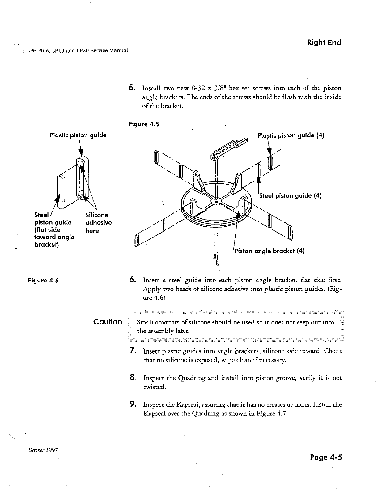
5.
Install
angle
of
two
brackets.
the
bracket.
new
8-32 x 3/8"
The
ends
of
hex
the
set
screws
screws
should
into
be
flush
each
with
Right
of
the
piston
the
inside
End
Steel
piston
(flat
toward
bracket)
Figure
Plastic
guide
side
angle
4.6
piston
Silicone
adhesive
here
guide
Figure
6.
4.5
Insert a steel
Apply
ure
4.6)
two
guide
beads
into
of
silicone
each
adhesive
Piston
piston
into
Plastic
~
:
angle
angle
plastic
piston
~
=.
bracket
bracket,
piston
guide
(4)
flat
guides.
(4)
side
first.
(Fig-
October
1997
Caution
=
-
7.
8.
9.
Small
the
amounts
assembly
Insert
that
Inspect
plastic
no
silicone
the
twisted.
Inspect
Kapseal
the
over
of
silicone
should
later.
guides
Quadring
into
is
exposed,
and
angle
wipe
install
Kapseal, assuring
the
Quadring
as
be
used
brackets,
clean
into
that
it
has
shown
so
it
silicone
if
necessary.
piston
no
creases
in
Figure
does
not
side
groove,
or
4.7.
seep
out
inward.
verify
nicks.
Install
Page
into
Check
it
is
not
the
4-5
Page 2
Repairs
LP6
Plus,
LP10
and
LP20
Service
Manual
Caution
Caution
©:
Be
very
careful
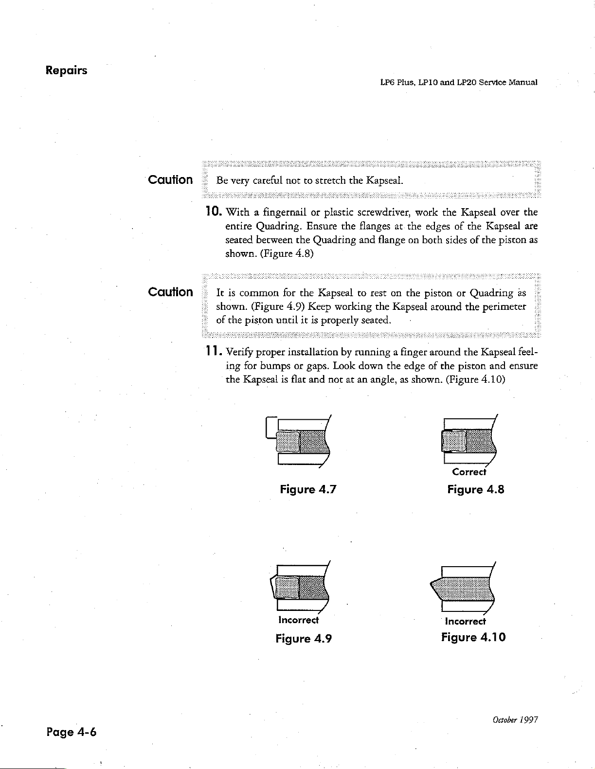
10.
With a fingernail
|:
It
»
shown.
©
of
entire
seated
shown.
is
common
the
piston
Quadring.
between
(Figure
(Figure
11.
Verify
ing
the
proper
for
bumps
Kapseal
not
to
stretch
or
plastic
Ensure
the
Quadting
4.8)
for
the
Kapseal
4.9)
Keep
until
it
is
properly
installation
or
gaps.
is
flat
and
the
Kapseal.
screwdriver,
the
flanges
and
to
rest
working
the
seated.
by
running a finger
Look
down
not
at
an
angle,
at.the
flange
on
on
the
Kapseal
the
edge
as
work
edges
both
piston
around
around
of
the
shown.
the
Kapseal
of
the
sides
of
or
Quadring
the
the
piston
(Figure
Correct
over
the
Kapseal
the
piston
as
perimeter
Kapseal
4.10)
and
feel-
ensure
are
as
©
..
|
Page
4-6
Figure
Incorrect
Figure
4.7
4.9
Figure
Incorrect
Figure
4.8
4.10
October
1997
Page 3
“\
LP6
Plus,
LP10
and
LP20
Service
Manual
Right
End
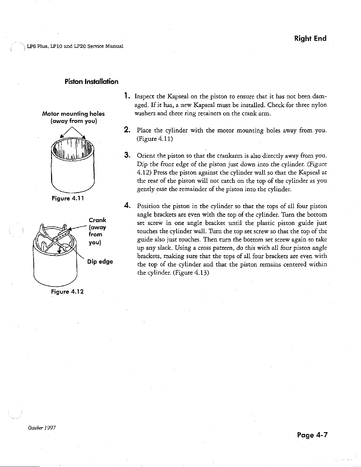
Motor
{away
Figure
Piston
mounting
from
4.11
Installation
holes
you)
Crank
(away
from
you)
Dip
edge
.
İnspect
aged.
washers
Place
(Figure
Orient
Dip
the
4.12)
the
rear
gently
Position
angle
set
screw
touches
guide
up
any
brackets,
the
top
the
cylinder.
the
Kapseal
If
it
has, a new
and
three
the
cylinder
4.11)
the
piston
front
edge
Press
the
piston
of
the
piston
ease
the
remainder
the
piston
brackets
in
are
one
the-cylinder
also
just
touches.
slack.
Using a cross
making
of
the
cylinder
(Figure
on
the
Kapseal
ring
retainers
with
the
so
that
the
of
the
against
will
in
the
even
with
angle
bracket
wall.
Turn
Then
sure that
and
4.13)
piston
piston
not
of
cylinder
to
must
on
motor
crankarm
just
the
cylinder
catch
the
piston
the
top
until
the
turn
pattern,
the
tops
that
the
ensure
be
installed.
the
crank
mounting
is
also
down
on
the
into
so
that
of
the
the
top
set
the
bottom
do
this
of
all
four
piston
that
it
has
Check
arm.
holes
directly
into
the
wall
so
that
top
of
the
the
cylinder.
the
tops
cylinder.
plastic
screw
with
so
set
all
piston
that
screw
brackets
remains
not
been
for
three
away
from
away
from
cylinder.
the
cylinder
of
all
Turn
four
centered
Kapseal
four
the
guide
the
top
again
piston
are
even
(Figure
bottom
dam-
nylon
you.
you.
ar
as
you
piston
just
of
the
to
take
angle
with
within
October
Figure
1997
4.12
Page
4-7
Page 4
Repairs
LP6
Plus,
LP10
and
LP20
Service
Manual
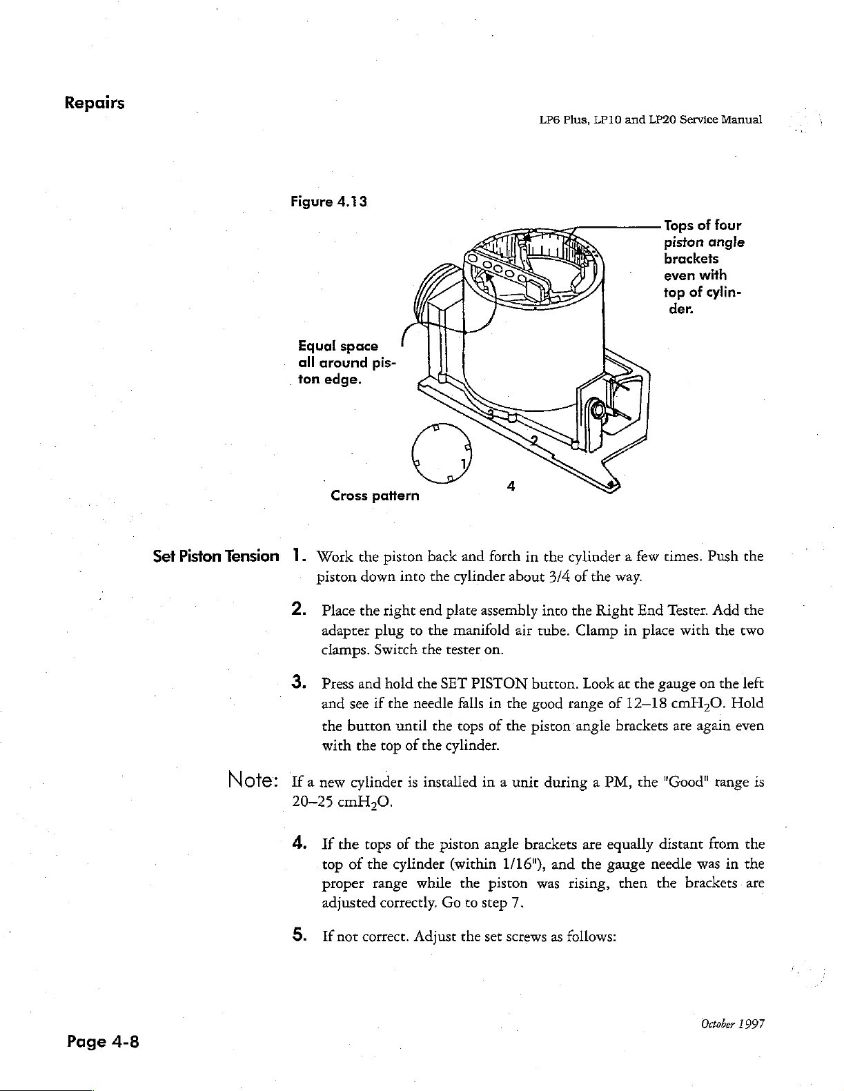
Set
Piston
Tension
Figure
Equal
all
around
ton
edge.
1.
Work
piston
4.13
space
Cross
the
down
Tops
of
four
piston
brackets
even
top
pis-
of
der.
angle
with
cylin-
pattern
piston
into
back
the
cylinder
and
forth
in
about
the
cylinder a few
3/4
of
the
way.
times.
Push
the
Note:
2.
Place
adapter
clamps.
Press
and
the
with
Ifa
new
20-25
4.
If
top
proper
adjusted
If
the
plug
Switch
and
see
if
button
the
top
cylinder
cmH,0.
the
tops
of
the
range while
correctly.
not
correct.
right
end
to
the
the
hold
the
the
needle
until
of
the
is
installed
of
the
cylinder
Adjust
plate
assembly
manifold
tester
on.
SET
PISTON
falls
the
tops
cylinder.
in a unit
piston
Go
angle
(within
the
to
step
the
air
in
the
of
the
1/16"),
piston
7.
set
screws
into
the
tube.
Clamp
button.
good
piston
brackets
was
Look
range
angle
during a PM,
are
and
the
rising,
as
follows:
Right
in
at
of
End
the
12-18
brackets
the
equally
gauge
then
Tester.
place
gauge
cmH,O.
are
"Good"
distant
needle
the
Add
with
the
on
the
Hold
again
range
from
was
in
brackets.
the
two
left
even
is
the
the
are
Page
4-8
October
1997
Page 5
Right
:
LP6
Plus,
LP10
and
LP20
Service
Manual
End
Note:
]
If
the
top
bracket
bracket
a.
b.
e.
set
screw
will
be
forced a little
to
ride a little
For
brackets
Verify
For
Verify
After
to
If
by
an
adjust
proper
After
to
bottom
brackets
bottom
adjustments
re-test
the
tension
the
gauge)
equal
screws
range
adjustments
re-test
is a little
tighter
higher.
lower.
that
are
too
set
screw
that
are
too
set
screw
are
made,
the
piston
amount
of
the
was
tension.
piston
outside
in
all
counter-clockwise
the
adjust
piston
screws
are
made,
tension.
than
The
high,
is
still
low,
is
still
return
against
the
of
the
clockwise
return
the
reverse
loosen
snug
tighten
snug
the
but
the
but
to
the
cylinder
proper
range,
brackets.
to
lower
ro
to
bottom
is
true
top
not
overly
top
not
overly
the
beginning
adjust
If
above
pressure.
raise
pressure.
the
beginning
screw
to
cause
set
screw
set
screw
wall
that
an
slightly.
tight.
slightly.
tight.
of
this test
(as
measured
all
set
proper
If
of
this
angle
angle
screws
range
below
test
6.
7.
Repeat
Check
steps
that
as
necessary
the
piston
to
obtain
is
centered
proper
in
the
leveling
cylinder.
and
tension.
October
1997
Page
4-9
Page 6
Repairs
LP6
Plus,
LP10
and
LP20
Service
Manual
System
Leak
Test
1.
Press
the
right
is
depressed.
is
released.
Press
the
manifold.
Remove
Remove
Apply a drop
bly
such
Push
Inspect
a.
b.
and
hold
side
and
the
the
that
the
piston
the
The
solenoid
All
three
erly,
and
the
must
Pressure
hold
the
assembly
air
tube
of
Loctite
the
about
Manifold
is
pieces
no
kinks
LEAK
stay
in
may
TEST
the
drop
VENT
from
adapter
242
Loctite
1/2
way
Assembly
securely
of
1/4"
are
present.
button.
GOOD
very
button
the
Right
plug.
on
each
flows
around
down
and
mounted.
internal
range
slowly
to
release
End
set
screw
the
into
verify
tubing
The
needle
when
when
the
Tester.
and
threads,
the
cylinder.
that:
are
of
the
the
leak
LEAK
TEST
pressure
tilt
the
wipe
present,
seated
gauge
test
button
button
from
inside
subassem-
off
excess.
prop-
on
Page
4-10
C.
Patient
secure,
Pressure
and
clean.
and
Exhalation
Valve
tubes
appear
straight,
October
1997
Page 7
i:
\LP6
Plus,
LP10
and
LP20
Service
Manual
Right
End
Motor/Gearbox
Installation
1.
Inspect
the
Motor/Gearbox
Wires
Wires
are
not
are
correctly
follows:
Wire
Color
red
yellow
black
Terminals
Two
Motor/Gearbox.
There
Motor/Gearbox.
dowel
is
no
are
and
damaged.
properly
pins
are
grease
Clean
positioned
present and
in
verify
Position
(+)
(0)
O
seated.
the
seam
the
gearbox
that:
on
magnetic
not
between
bent
of
sensor
in
the
any
residual
the
two
terminals
base
of
halves
of
grease.
as
the
the
|
October
1997
Key
is
flush
There
in
the
with
are
output
the
no
burrs
end
shaft
of
the
on
the
and
fully
output
key and
seated
shaft.
crank.
in
slot
and
its
Page
end
4-11
is
Page 8
Repairs
LP6
Plus,
LP10
and
LP20
Service
Manual
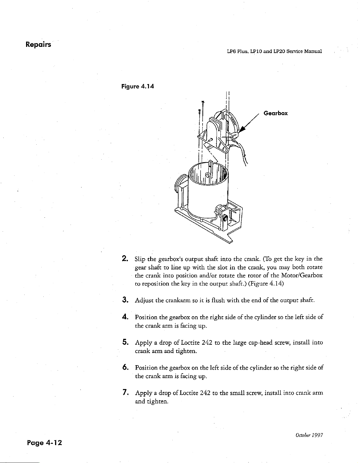
Figure
4.14
Gearbox
Slip
the
gearbox's
gear
shaft
to
the
crank
into
to
reposition
Adjust
Position
the
Apply a drop
crank
Position
the
Apply a drop
and
the
crankarm
the
crank
arm
arm
and
the
crank
arm
tighten.
gearbox
gearbox
output
line
up
position
the
key
is
facing
of
Loctite
tighten.
is
facing
of
Loctite
with
and/or
in
the
so
it
on
the
up.
on
the
up.
242
shaft
the
output
is
flush
right
242
left
to
into the
slot
in
rotate
shaft.)
with
side
to
the
É
side
the
small
crank.
the
the
the
of
the
large
of
the
screw,
(To get
crank,
rotor
(Figure
cap-head
you
of
the
4.14)
end
of
the
cylinder
cylinder
install
the
key
may
both
Motor/Gearbox
output
so
screw,
so
the
the
left
install
right
into
shaft.
side
side
crank
in
the
rotate
of
into
of
arm
Page
4-12
October
1997
Page 9
"i
LP6
Plus,
LP10
and
LP20
Service
Manual
Right
End
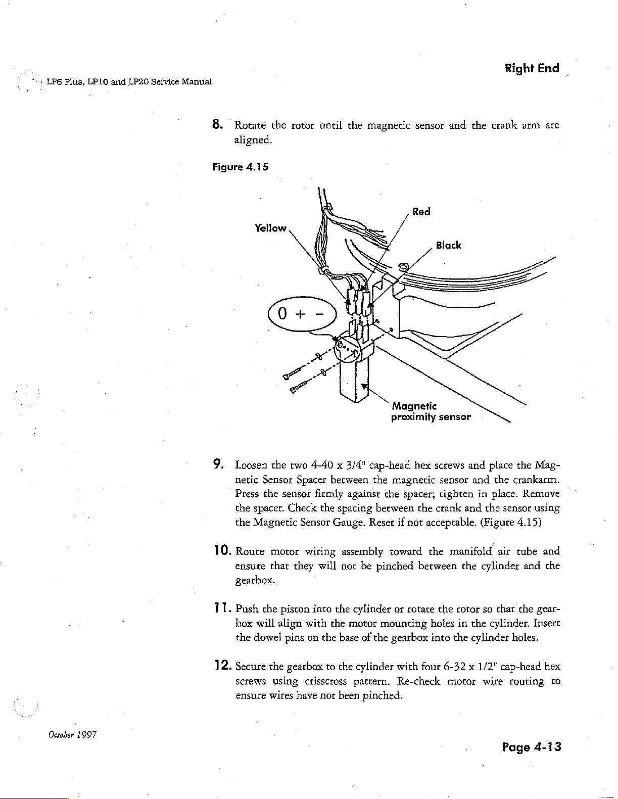
Rotate
8.
aligned.
Figure
the
rotor until
4.15
the
magnetic
sensor
and
the
crank
arm
are
Magnetic
proximity
sensor
October
1997
Loosen
netic
Press
the
spacer.
the
Magnetic
10.
Route motor
ensure
gearbox.
11.
Push
box
the
dowel
12.
Secure
Screws
ensure
the
Sensor
the
that
the
will
align
the
using
wires
two
Spacer
sensor
Check
Sensor
wiring
they
piston
with
pins
on
gearbox
crissctoss
have
4-40 x 3/4"
between
firmly
into
the
spacing
Gauge.
will
the
the
the
base
to
the
nor
been
against
assembly
not
be
cylinder
motor
of
cylinder
pattern.
pinched.
cap-head
the
magnetic
the
spacer;
between
Reset
if
not
toward
pinched
or
rotate
mounting
the
gearbox
with
Re-check
hex
screws
the
crank
acceptable. (Figure
the
between
holes
into the
four
and
sensor
tighten
the
and
in
and
the
manifold
the
cylinder
rotor
so
in
the
cylinder
6-32 x 1/2"
motor
wire
place
place.
cylinder.
the
the
crankarm.
Remove
sensor
4.15)
air
tube
and
that
the
holes.
cap-head
routing
Page
Mag-
using
and
the
gear-
Insert
hex
to
4-13
Page 10
Repairs
LP6
Plus,
LP10
and
LP20
Service
Manual
Bearing
Replacement
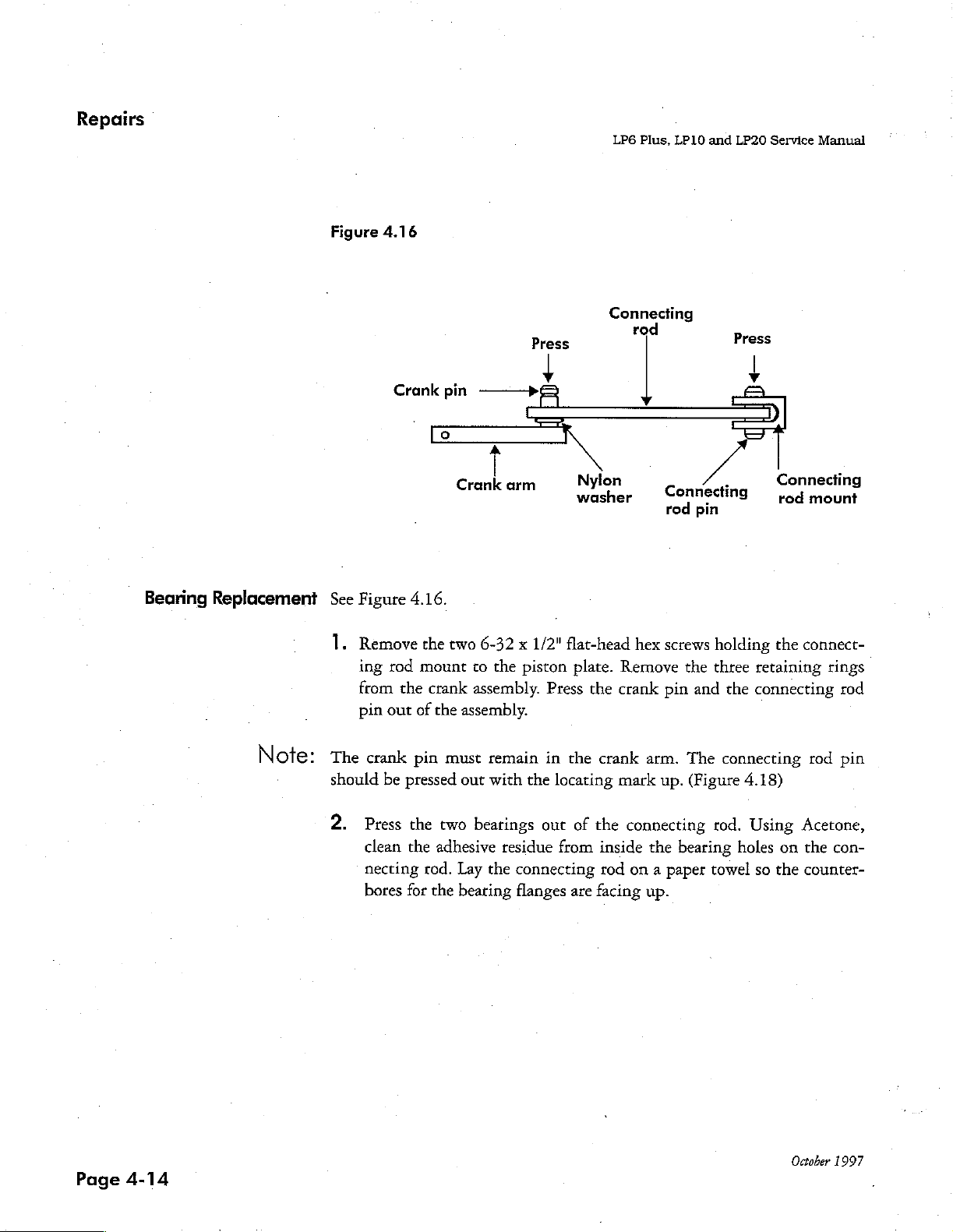
Figure
See
Figure
1.
Remove
ing
from
pin
4.16
Crank
rod
the
out
pin
4.16.
the
mount
crank
of
the
——>&
Crank
two
arm
6-32 x 1/2"
to
the
assembly.
assembly.
Press
+
piston
Press
Connecting
rod
Nylon
washer
flat-head
plate.
the
hex
Remove
crank
Connecting
rod
pin
screws
pin
the
and
holding
three
the
y
Connecting
rod
mount
the
connect-
retaining
connecting
rings
rod
Page
4-14
Note:
The
crank
should
2.
Press
clean
necting
bores
pin
be
pressed
the
the
for
must
out
two
bearings
adhesive
tod.
Lay
the
bearing
remain
with
the
out
residue
the
connecting
flanges
in
the
crank
locating
of
the
from
inside
rod
are
facing
arm.
The
mark
up.
(Figure
connecting
the
bearing
on a paper
up.
connecting
4.18)
rod.
Using
holes
towel
so
rod
Acetone,
on
the
the
counter-
October
pin
con-
1997
Page 11
LP6
Plus,
LP10
and
LP20
Service
Manual
Right
End
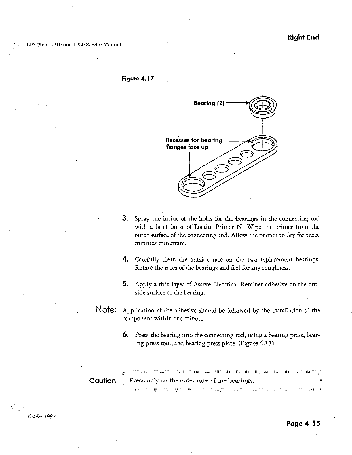
Figure
3.
4.17
Spray
with a brief
outer
minutes
Recesses
flanges
the
inside
burst
surface
of
minimum.
for
face
of
the
of
Loctite
the
connecting
earing
bearing
up
holes
for
the
Primer
rod.
Allow
ο
bearings
N.
Wipe
the
primer
in
the
the
connecting
primer
to
dry
from
for
three
rod
the
October
1997
Note:
Caution
4.
Carefully
Rotate
5.
Apply a chin
side
Application
component
6.
Press
ing
Press
the
surface
within
the
press
only
clean
races
layer
of
the
of
the
adhesive
one
bearing
tool,
and
on
the
the
outside
of
the
bearings
of
Assure
bearing.
minute.
into
the
bearing
outer
race
race
on the
and
Electrical
should
be
connecting
press
plate.
of
the
two
feel
for
any
Retainer
followed
rod,
bearings.
by
using a bearing
(Figure
replacement
roughness.
adhesive
the
on
installation
press,
4.17)
Page
bearings.
the
out-
of
the
bear-
4-15
Page 12
Repairs
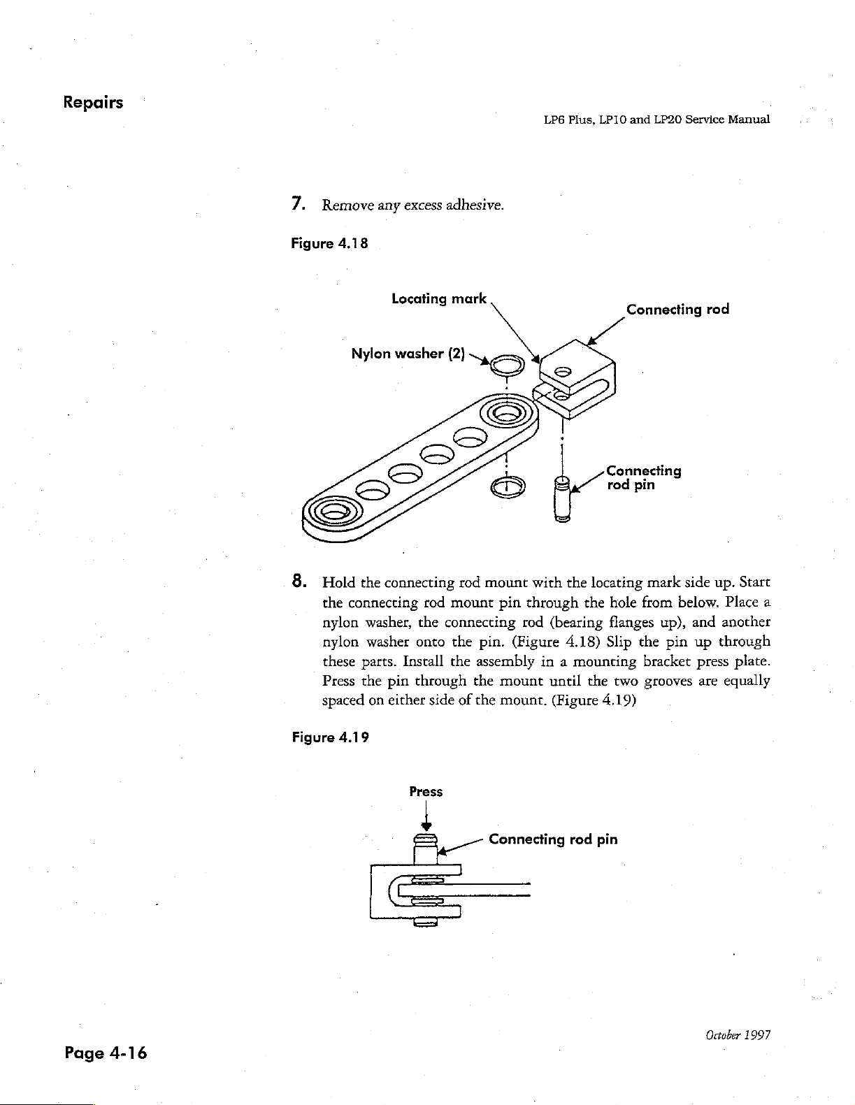
7.
Remove
any
excess
adhesive.
LP6
Plus,
LP10
and
LP20
Service
Manual
Figure
4.18
Nylon
Locating
washer
mark
(2)
8.
Hold
the
connecting
the
connecting
nylon
nylon
these
Press
spaced
washer,
washer
parts.
the
on
rod
the
onto
Install
pin
through
either
mount
connecting
the
the
side
rod
mount
pin.
assembly
the
of
the
with
pin
through
rod
(Figure
mount
mount.
Connecting
Connecting
rod
the
locating
the
hole
(bearing
4.18)
in a mounting
until
(Figure
flanges
Slip
the
two
4.19)
pin
mark
from
up),
the
pin
bracket
grooves
rod
side
up.
below.
and
up
through
press
are
Start
Place
a
another
plate.
equally
Page
4-16
Figure
4.19
Press
Connecting
red
pin
October
1997
Page 13
7
LP6
Plus,
LP10
and
LP20
Service
Manual
Right
End
Figure
Crank
4.20
arm
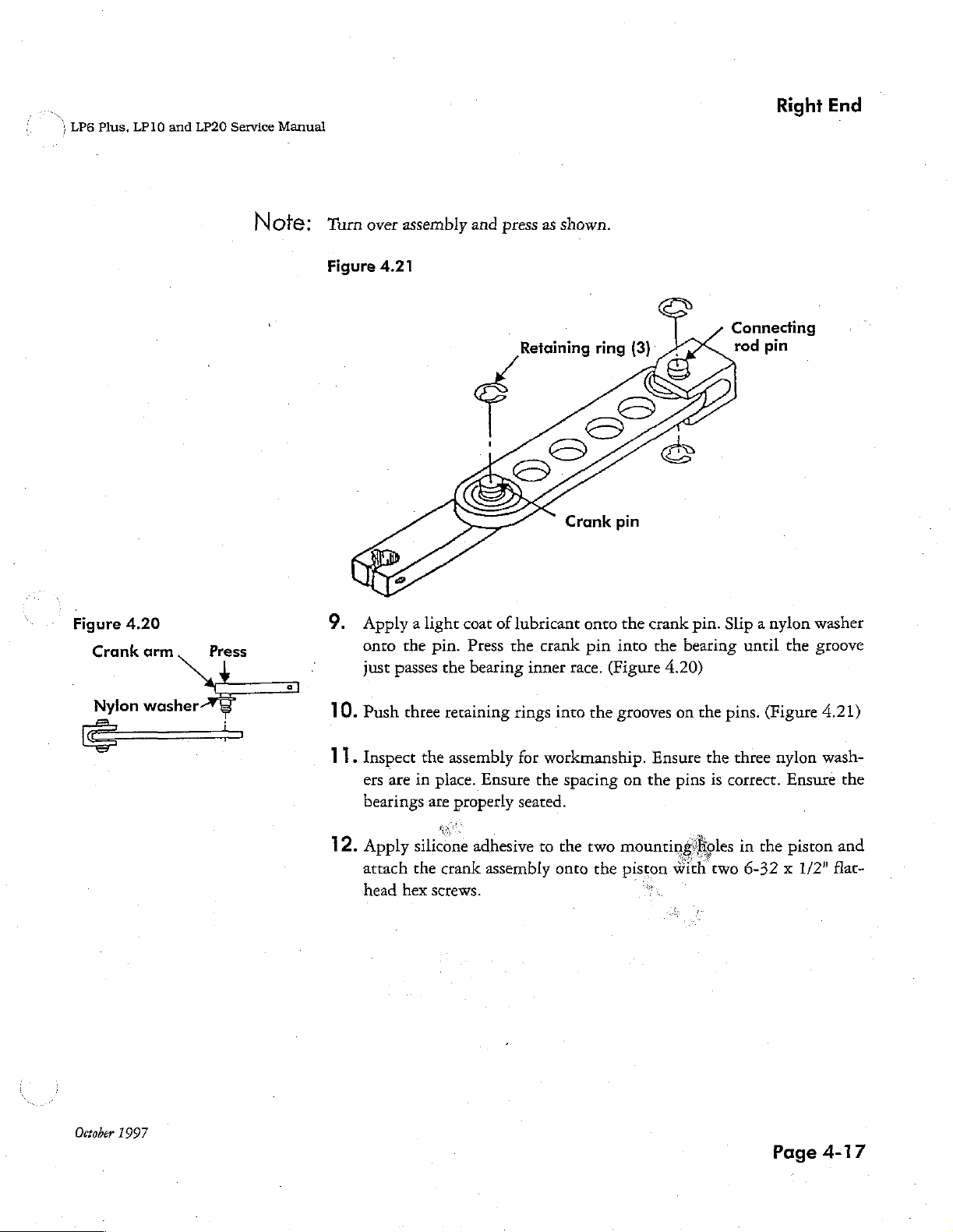
Note:
Turn
over
assembly
Figure
4.21
9.
Apply a light coat
onto
the
pin.
just
passes
the
and
press
of
lubricant
Press
the
bearing
as
shown.
Crank
crank
inner
onto
pin
race.
(Figure
pin
the
into
crank
pin. Slip a nylon
the
bearing
4.20)
Connecting
rod
pin
until
the
washer
groove
Nylon
October
1997
washer
10
11.
12.
.
Push
Inspect
Apply
attach
three
the
ers
are
in
bearings
silicone
the
head
hex
retaining
assembly
place.
are
screws.
Ensure
properly
adhesive
crank
assembly
rings
into the
for
workmanship.
the
spacing
seated.
to
the
onto
two
mountin
the
grooves
Ensure
on
the
piston
로
on
the
pins
Holes
with
pins.
the
three
is
correct.
in
two
6-32 x 1/2”
(Figure
nylon
Ensure
the
piston
Page
4.21)
wash-
the
and
flat-
4-17
Page 14
Repairs
:
LP6
Plus,
LP10
and
LP20
Service
Manual
Manifold,
Leaf
And/or
der
Replacement
Cylin-
1.
Manifold
a.
b.
9
a
2.
Remove
3.
If
ing
and
Remove
Remove
Separate
Remove
end
plate.
retainer
expiration
ring.
Cylinder
the
all
the
all
leaf
Removal
gearbox
16
screws
manifold,
gasket
ring,
filter
is
replaced,
and
piston
from
the
cylinder
material
screen
reinstall
Note:
low
volume
rates.
assemblies.
right
end
and
right
from
manifold,
and
O-ring,
O-ring,
Replace
delivered
Use
Kit
#1726
plate.
end
plate.
cylinder
if
necessary.
filter
screen
this
leaf
or
if
at
Kit
and
and
retain-
unit
low
flow
#1724.
right
has
Note:
leaf
#1724,
Page
4-18
Replace
vibration.
this
Use
leaf
Kit
#1670
for
internal
or
Kit
Figure
4.23
October
1997
Page 15
1126
Plus,
LP10
and
LP20
Service
Manual
Right
End
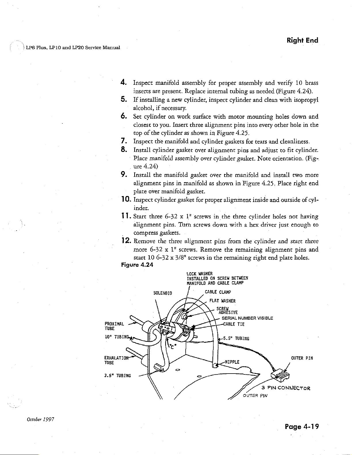
Inspect
inserts
If
installing a new
alcohol,
Set
closest
top
Inspect
æn
Install
Place
.
ure
Install
alignment
plate
10.
Inspect
inder.
11.
Start
alignment
compress
12.
Remove
more
start
Figure
4.24
manifold
are
present.
if
necessary.
cylinder
of
to
you.
the
cylinder
the
on
manifold
cylinder
manifold
4.24)
the
manifold
pins
over
manifold
cylinder
three
6-32 x 1"
pins.
gaskets.
the
three
6-32 x 1"
10
6-32 x 3/8"
SOLENOID
assembly
Replace
cylinder,
work
Insert
three
as
shown
and
gasket
assembly
gasket
in
manifold
gasket.
gasket
Turn
alignment
screws.
screws
LOCK
INSTALLED
MANIFOLD
for
internal
inspect
surface
with
alignment
in
cylinder
over
alignment
over
cylinder
over
as
for
proper
screws
screws
in
down
pins
Remove
in
the
WASHER
ON
AND
CABLE CLAMP
FLAT
proper
tubing
cylinder
motor
pins
Figure
4.25.
gaskets
pins
gasket.
the
manifold
shown
SCREW
CABLE CLAMP
SCREW
in
alignment
the
three
with a hex
from
the
remaining
remaining
BETWEEN
WASHER
ADHESIVE
SERIAL
assembly
as
needed
and
mounting
into
every
for
tears
and
adjust
Note
and
Figure
the
NUMBER
4.25,
inside
cylinder
driver
cylinder
right
VISIBLE
and
verify
(Figure
clean
with isopropyl
holes
down
other
hole
and
cleanliness.
to
fit
orientation.
install
Place
and
outside
holes
not
just
enough
and
start
alignment
end
plate
10
brass
4.24).
and
in
the
cylinder.
(Fig-
two
more
right
end
of
cyl-
having
to
three
pins
and
holes.
October
1997
3.5"
TUBING
OUTER
3
PIN
PIN
CONNECTOR
OUTER
Page
PIN
4-19
Page 16
Repairs
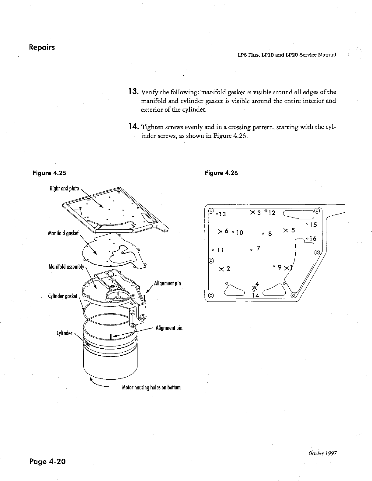
13.
Verify
manifold
exterior
14,
Tighten
inder screws,
the
following:
and
cylinder
of
the
screws
as
manifold
gasket
cylinder.
evenly
shown
and
in
LP6
gasket
is
visible
in a crossing
Figure
4.26.
Plus,
LP10
is
visible
around
pattern,
」
and
LP20
around
the
entire
starting
Service
all
edges
interior
with
Manual
of
the
the
and
cyl-
Figure
Manifold
Manifold
Cylinder
4.25
Right
end
gasket
assembly
gasket , a
Cylinder
plate
gs
SV
p
N
^
σ
の
LS
EN
(Te
È
Alignment
/
Alignment
9
pin
pin
P
Figure
4.26
Page
4-20
Motor
housing
holes
on
bottom
October
1997
Page 17
LP6
Plus,
LP10
and
LP20
Service
Manual
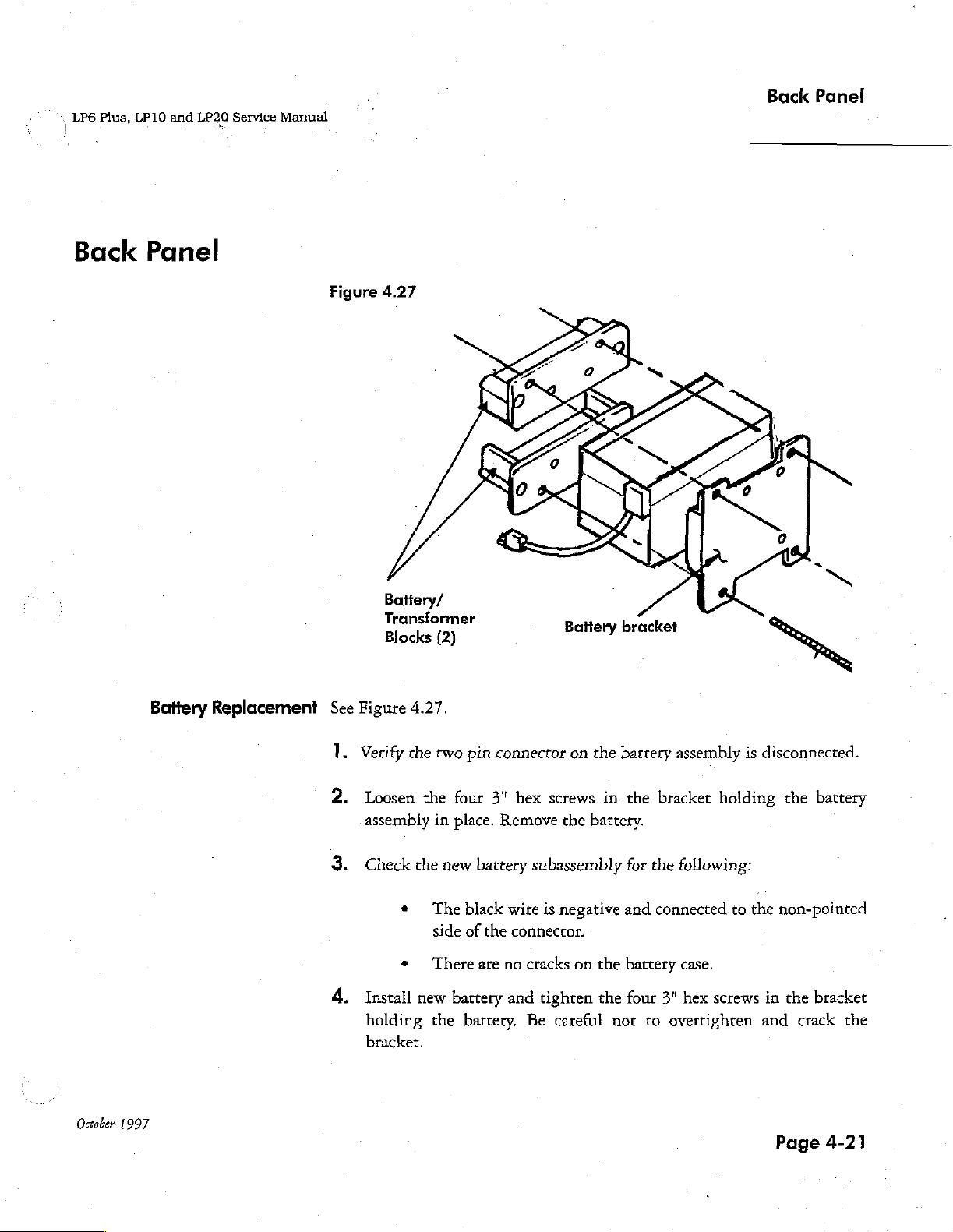
Back
Panel
Back
Panel
Figure
4.27
Battery/
Transformer
Blocks
(2)
Battery
bracket
x
October
1997
Battery
Replacement
See
1.
2.
3.
4.
Figure
Verify
4.27.
the
Loosen
assembly
Check
Install
holding
bracket.
the
che
e
e
new
two
pin
four
in
place.
new
The
black
side
of
There
battery
the
battery.
connector
3"
hex
Remove
battery
the
are
subassembly
wire
connector.
no
cracks
and
Be
on
the
screws
the
battery.
is
negative
on
tighten
careful
battery
in
the
for
and
the
battery
the
four
not
assembly
bracket
the
following:
connected
case.
3"
hex
to
overtighten
is
disconnected.
holding
to
the
screws
and
the
battery
non-pointed
in
the
bracket
crack
Page
4-21
the
Page 18
Repairs
LP6
Plus,
LP10
and
LP20
Service
Manual
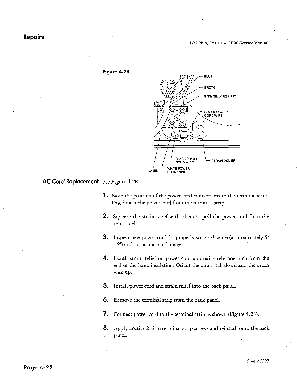
AC
Cord
Replacement
Figure
See
1
4.28
Figure
Note
Disconnect
4.28.
the
position
the
LABEL
of
the
power
cord
BLACK
CORD
WHITE
POWEA
CORDWIRE
power
from
cord
the
BLUE
BROWN
GRN/YEL
GREEN
CORD
POWER
WIRE
connections
terminal
WIRE
POWER
WIRE
STRAIN
to
strip.
ASSY.
RELIEF
the
terminal
strip.
Squeeze
rear
Inspect
16")
Install
end
wire
Install
a
Remove
の
N
Connect
Apply
©
panel.
the
panel.
new
and
no
strain
of
the
up.
power
the
power
Loctite
strain
relief
power
insulation
large
cord
relief
on
insulation.
cord
and
terminal
cord
242
to
with
for
properly
damage.
power
Orient
strain
strip
from
to
the
terminal
terminal
pliers
to
stripped
cord
approximately
the
relief
into
the
back
strip
strip
screws
pull
the
wires
strain
tab
the
back
panel.
as
shown
and
power
cord
(approximately
one
inch
down
and
panel.
(Figure
reinstall
4.28).
onto
from
from
the
the
the
5/
the
green
back
Page
4-22
October
1997
Page 19

Back
*
LP6
Plus,
LP10
and
LP20
Service
Manual
Panel
Replacement
of
AC
ON/OFF
Switch
Figure
See
1.
4.29
Figure
Disconnect
their
BROWN
RFI
WIRE
RFI
WIRE
FILTER
FROM
FILTER
FROM
BLUE
BLUE
WIRE
ASSY.
BROWN
4.29.
the
four
wires
location.
WIRE
on
ASSY.
the old
ON/OFF
switch,
taking
note
of
2.
Depress
remove
3.
Bend
the
4.
Install
toward
5.
Reconnect
OFF
to
two
old
ON/OFF
the
the
switch.
the
bottom
che
the
lugs
two
locking
switch
on
switch.
new
ON/OFF
bottom
the
four
The
wires
edge
from
the
new
edge
wires
of
the
tabs
the
ON/OFF
switch
of
the
to
from
back
on
each
back
back
their
the
panel
end
panel.
switch
in
the
panel.
previous
terminal
(Figure
of
the
ON/OFF
to
match
back
panel
locations
strip
go
4.29).
the
on
to
bent
with
the
the
switch
Ings
the
new
lugs
closest
and
on
zero
ON/
October
1997
Page
4-23
Page 20

Repairs
LP6
Plus,
LP10
and
LP20
Service
Manual
Front
Panel
Meter
Replacement
1.
Disconnect
two
#10
2.
Remove
3.
While
can
no
markings
exactly
meter
meter
4.
Check
dow
panel.
5.
Install
Install
flat
stud.
is
straight
Tighten
Kep
and
holding
be
adjusted
on
window.
window.
the
with
anti-static
one
meter
washer,
Mount
the
meter
nuts
discard
the
at
to
the
-10
when
Install
meter
flat
washer
bracket
one
lock
meter
by
looking
brass
wires
from
from
the
meter
the
old
meter.
replacement
least.
two
divisions
left
of
-10,
done.
Install
long
piece
window
to
for
spray
and
on
each
over
the
washer,
the
front
through
nuts
with a nut
J12
on
the
and
remove
meter
each
use
your
short piece
of
foam
scratches
wipe
of
the
four
round
and
portion
one
panel
meter
driver.
Logic
Board
the
wires.
vertically,
own
and
clean.
verify
side
of
judgment.
of
foam
around
the
debris.
Install
-10.
threaded
of
the
brass
nut
(finger
with
three
screws.
window
of
and
that
Since
Set
directly
sides
Spray
meter
studs
meter.
tight)
the
remove
the
there
the
and
meter
into
on
the
Install
on
Verify
top
overlay.
the
needle
are
needle
below
top
of
win-
front
meter.
one
each
meter
Figure
Page
Stud
Red
4-24
4.30
wire
6.
Check
no
damaged
meter
wire
insulation.
Meter
10-32
Kep
(2)
Black
assembly
nut
wire
for
proper
7.
Attach
the red
with a plus
to
4.30).
Kep
tighten
8.
Plug
Board
cuit
crimps,
meter
wire
(+)
the
other
To
secure
nut
on
with
connector
and
tuck
boards.
no
wire
over
and
stud
wires,
each
3/8"
to
wires
exposed
assembly
the
stud
the
black
as
shown
place a #10
stud
nut
driver.
J12
on
between
wire,
marked
(Figure
and
the
October
and
with
wire
hand
Logic
cir-
1997
Page 21

*,
LP6
Plus,
LP10
and
LP20
Service
Manual
Front
Panel
Circuit
Board
Removal
Caution
Figure
Use
panel
4.31
Tİ
of
and
E
an
anti-static
circuit
boards
Power/motor
|
|
|
M
Front
panel
workstation
safely.
is
board
5
|
Logic
pe
~
necessary
to
board
handle
the
=
front
Power/Motor
October
1997
Board
Removal
1.
Check
Board;
five
Board
2.
Remove
dampener.
3.
Raise
two
for
the
presence
install
6-32 x 3/16"
to
the
sets
resistor
the
stand-offs.
the 6 -
Power
of
pin
connectors.
32 x 3/4"
Motor
of
the
resistor
plug
for a minimum
button-head
(Figure
button-head
Board
carefully
hex
screws
4.31)
plug
of
hex
from
in
J3
on
one
minute.
securing
screw
from
the
front
the
Power/Motor
Remove
the
Power/Motor
the
heat
panel.
There
Page
the
sink
are
4-25
Page 22

Repairs
LP6
Plus,
LP10
and
LP20
Service
Manual
Logic
Display
Circuit
Board
Display
Board
Board
Replacement
Board
Installation
Removal
Note:
Removal
Do
not
1.
Turn
screws
rings
Remove
head
ing
Disconnect
Disconnect
Board.
.
Remove
the
the
.
Check
remove
all
seven
securing
(behind
the
hex
screw
the
Logic
(Raise
the
display
Display
the
Display
the
pressure
knobs
the
BREATHING
five
6-32 x 5/8"
and
Board
the
meter
the
Display
the
Logic
two
6-32 x 3/16"
board,
Board.
limit
completely
knobs
the
one
to
the
wire
Board
and
the
Remove
Board
for
knob
(LP1O
counter-clockwise.
to
the shafts.
EFFORT
and
stand-offs,
4-40 x 3/16"
front
panel.
assembly
Board
ribbon
from
the
button-head.hex
three
flat
head
the
Display
damaged
components
only).
Remove
the
the
VOLUME).
one
6-32 x 3/16"
button-head
from
J12
cable
from
front
panel.)
screws
screws
Board.
knobs
on
from
and
Loosen
hex
screw
the
Logic
J9 on
from
the
traces.
the:
and
the
button-
secur-
Board.
the
Logic
the
top
bottom
set
O-
of
of
Page
4-26
Note:
Check
that
Mount
head
head
The
Logic
tricity.
boards.
Take
the
ribbon
the:
*
Connectors
*
Wires
‧
Colored
connector.
the
the
Display
hex
screws
screws
on
Board
precautions
cable
are
are
not
broken.
line
on
(This
connector.)
Board
on
the
the
bottom
and
the
Power/Motor
to
on
the
replacement
fully
pressed
the
cable
is
the
pin
by
installing
top
of
the
of
the
eliminate
together.
is
connected
indicated
the
Display
Display
Board
static
before
Display
to
the
Board
#1
by a polarizing
two
6-32 x 3/16"
Board.
Board
are
Install
using
sensitive
handling
ensuring
pin
in
the
mark
button-
the
three
Loctite
to
static
242.
the
October
gray
on
flat
elec-
circuit
1997
Page 23

.
¡
LPG
Plus,
LP10
and
LP20
Service
Manual
Front
Panel
Logic
Board
Installation
1.
2.
3.
Check
*
*
©
*
*
*
*.
Mount
tighten
head
hex
Connect
nect
meter
the
Logic
Board
Theproperorientation
locking
No
component
No
trace
Nuts
on
Polarity
notch
indicators
All
leads
Presence
(U25
and
the
Logic
stand-offs
screw
and
Display
wiring
for
the
nuts
should
damage.
or
pad
damage.
switches
of
ROMs
are
of
U26).
Board
using a nut
one
Board
assembly
and
on
seated
"stick-on"
with
6-32 x 3/16"
ribbon
following:
ofthe
transducer
be
on
the
pots
are
by
matching
the
board.
correctly
labels
driver.
to
J12
and
on
five
6-32 x 5/8"
Install
button-head
cable
to
on
the
mounting
transducer
tight.
the
notches
not
bent.
the
two
large
one
4-40 x 3/16"
J9
on
the
Logic
Board.
screws.
side.)
on
ROMs
EPROM
stand-offs.
button-
hex
screw.
Logic
Board.
(The
to
the
chips
Hand-
Con-
:
October
1997
Figure
4.32
STM
al
E
i
i
Power/motor
|
Front
panel
$
|
|
я
board
Logic
board
기
Page
Y
|
|
|
YA
4-27
Page 24

Repairs
LP6
Plus,
LP10
and
LP20
Service
Manual
Power/Motor
Installation
Board
1.
2.
3.
A.
Check
the
Power/Motor
No
The
of
Polarity
on
EPROM
EPROM
Carefully
pins
onto
Check
bent
Secure
in
the
the
all
and
the
mount
pins.
the
all
hex screws.
Board
component
resistor
the
the
Logic
(Figure
pins
pins
plug
board
away
of
EPROM
ROM
to
leads
are
has a label.
the
Power/Motor
Board.
4.32)
connecting
are
fully
Power/Motor
to
damage
is
inserted
from
(U10)
the
notch
seated
Press
the
seated
Board
ensure
exists.
into
the
heat
is
correct
indicator
correctly
Board
the
Power/Motor
boards
into
the
using
five
that:
the
J3
connector
sink).
by
matching
on
the
and
not
by
positioning
Board
to
make
sure
connectors.
6-32 x 3/16"
(at
the
board.
bent.
it
evenly
that
no
button-head
the
corner
notches
over
down
pins
the
are
Page
4-28
5.
Install a 6-32 x 3/4"
dampener
to
the
button-head
front
panel.
hex
screw
to
secure
the
heat
sink
October
1997
Page 25

|
LP6
Plus,
LP10
and
LP20
Service
Manual
Front
Panel
Knob
Installation
1.
2.
3.
Note:
The
ting
4.
Verify
all
shafts
on
the
Place
O-rings
brass
nuts
with
respect
ing
with a .025
Tighten
Take
five.5/8"
feeler
gauge
counter-clockwise)
indicators
marks
Check
that
on
that
there
(VOLUME
the
set
on
the
all
is
some
into
locking
to
the
minimum
feeler
screws
regular
and
orient
setting
the
knobs
overlay.
knobs
tension
front
and
gauge
in
each
knobs.
indicator
must
are
in
on
panel
are
knobs
BREATHING
and
overlay
between
knob.
Obtain
marks
on
align
fact
turned
the
locking
fully
counter-clockwise.
install
markings.
lines
the
precisely
onto
the
EFFORT).
Position
Obtain
the
knob
and
correct
overlay.
fully
knobs
spacing
at
the
minimum
Tighten
with
the
counter-clockwise.
during
two
shafts
the
correct
the
front
panel.
with a .025
(furthest
knobs.
minimum
Check
rotation.
with
knobs
spac-
set-
October
1997
Page
4-29
Page 26

Repairs
LP6
Plus,
LP10
and
LP20
Service
Manual
Overlay
Replacement
Figure
See
1.
4.33
Striker
Figure
4.33.
Remove
pletely
overlay
2.
Check
silk-screening
3.
Remove
both
front
anti-static
plate
the
overlay
from
the
is
adhered
overlays
adhesive
and
spray
front
will
for
or
holes)
backing
back
and
to
be
replaced.
panel.
Residue
cause a bubble
flaws
(scratches,
before
installing.
from
of
meter
wipe
to
prevent
window
Scrape
left
on
or
bump.
discoloration,
top
overlay
area
spotting.
Top
the
adhesive
the
front
window,
of
the
overlay
residue
panel
bubbles,
if
present.
top
overlay
com-
where
the
illegible
Spray
with
Page
4-30
4.
The
G.
D.
5.
Check
following
for
Peel
Position
adhesive
backing
removed
Peel
overlay
Smooth
Check
the
all
overlays
continuous
are
suggestions
adhesive
back a small
the
overlay
portion
while
to
back
on
overlay
overlays
as
needed.
pressing
avoid
the
entire
panel
from
to
of
air
lightly
ensure
on
for
installing
portion
of
accurately
the
overlay.
down
bubbles
overlay,
and
center
to
edges
the
back
the
the
overlay
and
then
Now
the
overlay
from
being
carefully
press
up
outside
are
even
of
the
overlay.
overlays:
backing
press
down
peel
the
as
trapped.
holding
the
center
edges.
with
panel
on
one
the
exposed
remainder
the
backing
the
edges.
of
the
overlay.
edges.
Smooth
October
end.
of
1997
the
is
Lay
Page 27

Front
\
LP6
Plus,
LP10
and
LP20
Service
PLC
Replacement
(LP10/LP20
PLC
Manual
only)
Removal
1.
2.
Remove
Remove
Valve"
the
PLC
the
bezel
printed
on
knob
and
overlay
it.
knob
with
spring,
using a 1/16" hex
"Patient
Pressure"
and
Panel
driver.
"Exhalation
PLC
Installation
Remove
Remove
driver.
Remove
Remove
Remove
64"
Remove
1.
Fasten
hex
Rotate
pointing
Install
hex
the
head
the
the
two
the
two
the
bezel.
the
gasket
the
four
driver.
the
PLC
PLC
screws,
the
PLC
to
the
patient
Phillips
hex
head
from
hex
head
Manifold.
manifold
and
tighten
knob
shaft
right
of
the
pressure
head
screws
screws
around
screws
to
the
from
from
the
patient
from
the
ventilator's
using a crisscross
clockwise
until
assembly.
port
gasket.
the bezel.
the
bezel,
pressure
PLC
front
pattern.
the
using a 7/64"
port.
manifold,
panel
two
using a 5/
with
set
screws
the
hex
four
are
October
1997
Set
the
bezel
Install
using
Install
using
two
only
two
only
Phillips
light
hex
light
Install a new
onto
the
head
pressure.
head
pressure.
bezel
overlay
PLC
manifold.
screws
Do
screws
Do
over
in
in
not
the
not
the
the
top
over
tighten.
bottom
over
tighten.
two
of
the
bezel.
of
the
bezel.
Phillips
head
Hand
Hand
screws.
Page
tighten,
tighten,
4-31
Page 28

Repairs
PLC
Knob
Installation:
1.
Install
shaft
the
busing.
coil
spring
over
LP6
the
adjustment
Plus,
LP10
shaft
and
LP20
to
Service
rest
around
Manual
the
2
3
4,
5
6
Install
Align
Apply
Compress
Install
the
Check
knob
notches
adhesive,
the
flat
side
the
base,
grooved
in
knob
LOCTITE
the
spring
top
knob
of
the
shaft.
function
of
base
with
on
the
Tighten
the
side
connecting
to
the
corners
425,
to
the
knob
adjustment
the
locking
knob.
the
base
set
with
of
top
knob
and
shaft,
screw.
the
the
shaft
hold
with
spring.
set
screw
down.
the
busing.
threads.
set
screw
on
Page
4-32
October
1997
Page 29

Forms
On
the
the
LP6
*
Ventilator
e
Ventilator
following
Plus,
LP10,
Run-In
Service
pages
and
Log
Record
are
LP20
blank
Volume
copies
of
Ventilators.
the
forms
These
used
forms
when
are
servicing
the:
Photocopy
your
ventilator.
ensure
You
Nellcor
Volume
accurate
must
Puritan
Ventilator.
these
forms
and
use
Use
these
forms
records
complete a Service
Bennett
ate
each
kept
them
for
about
Record
time
to
document
your
necessary
and
Run-In
you
repair
maintenance
internal
documentation
maintenance
Log
an
LP6
and
and
return a copy
Plus,
LP10,
and
repair
repairs.
or
and
LP20
of
to
to
October
1997
Page
5-1
Page 30

Forms
LP6
Plus,
LP10
and
LP20
Service
Manual
Page
5-2
October
1997
Page 31

NELLCOR
PURITAN
Ventilator
Dealer:
Address:
Reason
for
return:
Inspection
LEDSs/Alarms
Part/Procedure
results:
Service
Pass/Fail
Serial
number
Record
Tech | Date
Technician:
Software
Work
Check-In
level
performed
Serial
Number:
Model:
Start
Date:
BENNETT.
Hours
in:
Visual
Controls
Alarm
check/output
Volume
Assembly
Stability
Relief
Valve
Power
Switch
High
alarm
FINAL
INSPECTION
test
(<4)
(<35)
Calibration
Reassembly
Calibration
Reassembly
Begin
Run-In
End
Run-tn
Begin
Run-In
End
Run-In
Final
Final
P=poss
F=fail
Visual
Controls
Alarm
check/output
Volume
Relief
Valve
Power
Switch
High
alarm
Assembly
FINAL
INSPECTION
test
Stability
(<4)
(<35)
P=poss
F=fail
Date:
Signature:
Hours
out:
Page 32

Forms
LP6
Plus,
LP10
and
LP20
Service
Manual
Page
5-4
October
1997
Page 33

NELLCOR
PURITAN
BENNETT.
Ventilator
Serial
Number:
DATE
1-day
run
complete
1-day
run
complete
1-day
run
complete
TIME
Run-In
“Name
Log
OCCURANCE
Begin 1 day
Begin
End
End 1 day
Name
Begin 1 day
Begin
End
End 1 doy
Begin 1 day
Begin
End
End 1 day
Name
run-in.
battery
run-down
battery
run-down.
run-in,
run-in.
battery
run-down
battery
run-down.
run-in.
run-in.
battery
run-down
battery
run-down.
run-in.
Begin
16
Begin
16
Begin
16
minutes
hour
run.
minutes
hour
run.
minutes
hour
run.
to
low
to
low
to
low
power.
power.
power.
Notes:
Page 34

Forms
LP6
Plus,
LP10
and
LP20
Service
Manual
Page
5-6
October
1997
Page 35

NOU-@3-1999
69:58
Mallinckrodt
Tech
SUpport
6126943883
F.02/03
Initial
Ventilator
Nelleor
The
purpose
may
also
ating
Check-Out
Modeli
0.
Puritan
properly.
be
Bennett,
of
this
used
for a brief
procedure
Inc.,
inspection
Procedure
1
General
Exterior
Appearance:
Any
broken
orloose
Imobs,
Any
dants
or
scratches
Condition
-
Eneure
Is
İs
2.
Enguré
Ensure
=
4
Set
AG
Mode
Low
High
Volume
Breath
Inspiratory
Breathing
Pressure
Note:
These
tings.
5.
Funcional
Plug
BREATHING
BREATHING
‘Connect a patient
EXHALATION
Set
All
An alarm
Only
‘The
PATIENT
Disconnect
EXHALATION
should
of
the
that
no
the
exterior
af
setting
information
that
a new
that
the
contro!
Power
Switch
Alarm
Alarm
Rate
Time
Effort
Limit
are
test
Testing:
tha
unit
EFFORT
tha
MODE
front
panel
sounds
the
AC
ventilator
PRESSUHE
the
indicate
surface
the
into
EFFORT
VALVE
PWH/SATT.
VALVE
which
AC
power
cord?
Squid
spills
have
tres
of any
on
the
alr
inlet
PATIENT
knobs
as
follows:
(LP20,
LP10,
.
(LP20,
LP1Q
settings
and
an
AC
power
famp
just
knob
back
circuit
and
port,
switch
lo
ABSIST/CONTROL
lamps
light
momentarily
momentarily
CHARGE
cydes
with
no
registers
patient
cireult.
port.
Measure
10604100
må.
PRESSURE
α
and
has
conducted
is
to
provide
ewitches,
may
indicate
leaked
foreign
front
panel
filter
[x
installed.
LP6
Plus
・
oriy)
not
typical
sourne.
comes
to
5.
test
lung
lamp
alarm
conditions
with
each
Attach a respiromatey
tha
Performance
several
instructions
of a ventilator
rubber
feat,
filter
dropping
or
into
the
ventilator.
material?
behind
the
neadle
Is
within
only)
-
'
palient
set.
Tum
the
BREATHING
an.
it
should
Eght
to
the
PATIENT
remains
lit
machine
cycle”
to
volume
delivered
quality
for the
which
.
housings,
other
abuse?
|
door
legible?
one
division
On
Standby
a
90
10
8
89
-5
Fuly
EFFORT
close
to
AIR
tube,
the
PATIENT
at
the
PATIENT
PURITAN
BENNETT.
‘Ventilator
tests
on
completion
has
not
had
ete?
of
-10.
(LP20/LP10/.P6
(approx.)
clockwisa
knob
foward
the
“0”
marking.
PATIENT
PRESSURE
AIR
tube
AIR
Inspection
Serial
Number:
this
ventilator
of
any
zero
Setihe
por,
and
black
tube; the
before
an
initial
inspection
internal
respirameter
Plug)
Battery
until
the
and
the
repairs
Charge
shipment.
upon
performed
Pass
σος
σισιος
(LPS)
-
a
ojooooan
receipt.
to
This
ensure
Fail
procedure
that
it
is
'
0000698
a
0000800
oper-
09-095200-000
Е
Page 36

Page 37

MV
-BS-1333
89:59
Mallinckrodt
Tech
Support
6126943883
P.Ø3/Ø3
Procedure
Connect
EXHALATION
When
Disconnect
Press
Piug
‘The
Set
Sat
Note
tre
patient
VALVE
fhe
pressure
exhalation
LIMIT
should
alarm
LP20
‘The
An alarm
The
Press
Press
The
The
LOWC
Unplug
‘The
An
‘Tha
The
Press
«Press
‘The
The
10\
Plug
To
butions
plied
or
(LPG
The
any
manifold
to
$0
and
presging
the
tast
sound
(dual-tone
by
pressing
only:
Press
the
ALARM
an
external
POWER
SWITCHOVER
sounds
EXTERNAL
patent
lho
and
EXTERNAL
battery
BATTERY
pressure
ALARM
hold the
BATTERY
condifion
MEDIUM
tha
external
POWER
SWITCHOVER
alarm
sounds
INTERNAL
patient
and hold
INTERNAL
battery
BATTERY
pressure
the
ALARM
the
BATTERY
condition
MEDIUMDI © HIGHO — (ow
he
AC
power
chack
the
number
at
the
same
by
200
(100
LPS
Plus,
10 = 2000
only)
of
legs
number
of
hours
the
MODE
switch
the
AC
POWER
comments
circuit
and
test
port.
Sat the
exceeds
60, a high
on
the
patient
the
ALARM
lung
from
the
on
the
LPS,
the
ALARM
SHLENCE/RESET
the
ALARA
SILENCE/RESET
SILENCE/RESET
battery
into
the
back
lamp
lamp
fights
continues
SILENCERESET
BATTERY
on
the
to
TEST
lamp
blinks
PATIENT
HIGHT
battery
lamp
lamp
lights
continues
SILENCEMESET
BATTERY
on
cord
of
time,
for
tha
than
to
switch
on
to
TEST
lamp
continues
the
PATIENT
back
into
hours
on
The
value
LPG)
will
hours,
for
380
(LPG
currently
on
STANDBY
10
OFF
inspection
Jung
to
the
PATIENT
HIGH
ALARMILIMIT
pressure
circuit
shotri
SILENCEMESET
patient
circuit.
double-pulsed
switch.
bution. The
bution
again.
of
the
ventflater.
blinks
cycle
with
each
button
to
reset
button
PRESSURE
Δον
battery
blinks
cycle
with
each
bution
to
reset
button
to
blink
PRESSURE
battery
an
AC
power
the
ventilatar,
pointed
to
correspond
LPS
Plus,
the
(OFF
(LP20,
unit,
to
10 « 1000
LP10,
LP2D),
ventilator:
on
the
LPS)
LP10,
comective
AIR
to
60
alarn
should
open.
Reset
svdich.
After
two
on
the
Tha
SETTING
Unplug
machine
the
alarm
meter
charge
machine
the
alarm
meter
charge
source
press
the
by
the
needle
the
numbar
hours).
*
and
LPG
action
tube,
PATIENT
and
compres
sound
the
cycles,
LP20},
SETTING
ERROAPRESLENCE
the AC
cycle
indicates
is
not
cycle
indicates:
ls
nol
ALARM
on
of
Note:
hours
Plus
only)
the
and
tha
alarm
by
retuming
the
LOW
PRESSURTIAPHEA
Reconnect
ERROR/PRESILENCE
power
acceptable)
accentable)
SILENGEMESET
the
PATIENT
operating
hours,
will
not
taken, or
PRESSURE
recommendations
port,
and
test
lung
in
your
mushroom
the
cord
PRESSURE
register И less
valve
the
HIGH
test
lung.
LED
and
BATTERY
(8.0.
for
LED
will
mater
LP20,
than
hand.
in
ALARM
alarm
Reset
will
turn
mulfi-
250
Pass
he
the
fight.
off.
TEST
LPIO,
.
for
further
Fail
o
a a
а a
0
Q q
a a
a
n
Q
а
G
a
a
Q
a
a
a
a a
a
action.
a
.а
a
с’
„A
」
'
Dat
e
O...
*<<ÂÂ
.
Inspection
performed
by:
TOTAL
P.
Page 38

Page 39

Equipment
Calibration
Calibration
of
Model
Note:
6960
Perform
1.
Remove
ventilator
from
2.
Connect
MUNICATION
3.
Plug
Standby.
4.
Monitor
connector
5.
Remove
screwdriver,
tored
this
procedure
the
the
harness.
the
the
the
the
voltage
Calibrator
at
least
left
side
cover
that
is
ready
for
Calibrator
PORT
of
the
ventilator
Set
the
DC
on
the
bottom
adjust
is
into
back
panel
voltage
Calibrator.
cover
R60
13.80+0.01
every
three
months.
from a functional
calibration.
to
the
Internal
ventilator.
AC
power
ON/OFF
across
of
on
the
VDC.
the
Power/Motor
switch
the red
ventilator.
LPG
Plus,
Disconnect
Battery
and
and
harness
set
the
to
ON.
black
wires
Using a non-conductive
board
the
internal
MODE
such
LP10,
and
the
of
the
that
or
LP20
battery
COM-
switch
two-pin
the
moni-
to
October
1997
Note:
6.
Adjust
until
Do
not
readjustment
7.
Press
pot
8.
Pull
calibrated
the
the
press
and
on
the
the
CHARGE
VOLTAGE
the
CHARGE
is
necessary,
hold
the
Calibrator
syringe
on
pressure
VOLTAGE
LED
button
wait
CHARGE
until
the
Calibrator
meter
lights
three
button;
the
voltmeter
to
the
pot
on
solidly.
for
longer
minutes
adjust
to
the
open
brass
the
than
and
then
the
shows
end
port.
bottom
10
of
of
seconds
repeat
CHARGE
10.50+0.01
its
stroke
Page
the
Calibrator
at a time.
the
step.
CURRENT
VDC.
and
attach
6-1
If
a
Page 40

Equipment
Calibration
9.
Apply
50+0.1cmH;0.
10.
Adjust
50
CM
11.
The
play
pressure
the
PRESSURE
LED
lights
contrast
contrast
of
pot
with
solidly.
the
display
on the
the
syringe
pot
on the
can
be
Calibrator.
LP6
Plus,
LP10
until
the
Calibrator
set
as
desired
and
LP20
pressure
until
the
by
adjusting
Service
meter
PRESSURE
Manual
indicates
the
dis-
Page
6-2
October
1997
Page 41

Calibration
.
| ;
LP6
Plus,
LP10
and
LP20
Service
Manual
of
Model
6951
Right-end
Tester
Calibration
of
Model
Note:
6951
Perform
1.
this
Disconnect
the
face
Connect a large
on
the
Apply
sure
meter.
Using
reads
12.
Apply
sure
meter.
Repeat
Right-end
procedure
the
plates.
left.
12+0.2
the
zero
18+0.2
The
this
step
at
tubing
syringe
cmH,0
screw,
cmH)O
left
for
pressure
Tester
least
every
six
from
the
two
and a calibrared
of
pressure
adjust
pressure
the
needle
pressure,
as
gauge
readings
months.
pressure
pressure
as
indicated
of
the
indicated
should
of
20
cmH,0
gauges.
indicate
meter
by
the
left
pressure
by
the
Carefully
1842.0
and
remove
to
the
gauge
calibrated
-
calibrated
25
gauge
cmH,0.
cmH0.
pres-
so
pres-
it
8.
9.
10.
11.
Connect
gauge
Apply
sure
Using
Remove
Install
Check
on
100+0.2
meter.
the
the
the
the
syringe and
the
right.
zero
screw,
the
syringe
face
plates
system
cmH,0
adjust
and
and
for
leaks
the
calibrated
pressure,
the
needle
pressute
securely reattach
and
signs
pressure
as
indicated
of
meter.
of
wear.
the
the
meter
by
the
gauge
tubing
to
the
pressure
calibrated
so
it
reads
to
the
gauges.
pres-
100.
October
1997
Page
6-3
Page 42

Equipment
Calibration
LP6
Plus,
LP10
and
LP20
Service
Manual
Page
6-4
October
1997
Page 43

Technical
Keep
technical
Bulletins
bulletins
in
this
section.
October
1997
Page
7-1
Page 44

Technical
Bulletins
LP6
Plus,
LP10
and
LP20
Service
Manual
Page
7-2
October
1997
Page 45

Miscellaneous
Information
Keep
miscellan:
formation
in
this
section
Page
8-1
Page 46

Miscellaneous
Information
LP6
Plus,
LP10
and
LP20
Service
Manual
Page
8-2
October
1997
Page 47

LP6+/LP10/LP20
KIT
L-1710
L-1719
L-1721
L-1722
L-1622
L-1603
L-1605
L-1671
L-1606
L-1672
L-1690
L-1675
L-1688
L-1702
NUMBER
L-1602
L-1689
L-1686 A 959.00
L-1687
L-1720
L-1691
L-1705
L-1706
L-1707
L-1703 £ 14,00
L-1617
VSA
00
SERVICE
КП
Adapter,
Adhesive,
Adhesive,
Adhesive,
Bail
Locks,
Port
Internal
Bearing,Crank
Block,
Bracket,
Bracket,
Breaker
Cable,
Cable,
Cap,
Filter
Carton,
Circuit
Circuit
Circuit
Clamp,
Cord
AC
Cover,
Cover,
Cover,
Cover,
Cover,
Ventilator
REPLACEMENT
DESCRIPTION
Test
Plug
Loctite
Loctite
Loctite
Battery
Battery
Meter
Universal
DC
Calibrator
Ribbon
Shipping
Board,
Board,
Board,
Solenoid
Bottom
Left
Right
Top
Port
242
Primer
642
Communication
-
Battery
circuit
Display
Logic
Power
LP6+/10
Motor
LP6+/10
N
Service
CONTENT
2
1
1
1
642
2
1
1
1
1
2
1
1
1
5
5
1
1
1
1
1
1
Board
1
1
1
1
1
1
1
1
1
1
1
1
1
1
1
1
2
1
Kits
KIT
Test
Plug
Adapters
bottle
Loctite
bottle
Primer
bottie
Adhesive
Bail
Locks
internal
Crank
Battery
Meter
Universal
DC
Calibrator
Ribbon
Filter
Labels
Poly
Insert
Carton
Display
Logic
Power
Clamp
Lock
Flat
Screw
Cable
Piece
AC
Warning
Bottom
Piece
Left
Piece
Caution
Right
Piece
Top
Screws
Communication
Battery
Bearing
Block
Bracket
Battery
Circuit
Cord
Breaker
Cable
Cable
Caps
Bag
Board
Board
Motor
Washer
Washer
Tie
Tubing
Label
Cover
Sound
Cover
Sound
Label
Cover
Sound
Cover
LIST
242
N
Loctite
Brackets
Circuit
Foam
Foam
Foam
Port
LOV
Cover
Page
1
Page 48

Page 49

Ventilator
Service
Kits
L-1714
L-1699
KIT
L-1618
L-1638
L-1640
L-1666
L-1680
L-1695
L-1621
L-1696
L-1718
L-1715
L-1670
L-1725
L-1724
L-1624
L-1
708
NUMBER
Cylinder
Decorative
KIT
Fan
for
Feet,
Feet,
Gasket,
Guide,
Handle,
Kapseal/Quadring
Knob,
Knob,Locking
Knob,
Leaf,
Leaf,
Leaf,
Magnetic
Manifold
Strip,
DESCRIPTION
LP6+/10/20
Bottom
Cord
Manifold
Manifold
Manifold
for
LP6+/10/20
Wrap
Cylinder & Manifold
Plastic
Front
PLC
Piston
Molded
Panel
for
LP10/20
for
for
for
Strip,
Control
Assembly
Front
Panel
for
LP6+/10/20
LP6+/10
LP6+/10
LP6+/10
Door
1
Cylinder
1
Cylinder
2
Danger
2
Decorative
CONTENT
1
Fan
12
Bottom
12
Screws
4
Cord
(4
Screw
5
Manifold
5
Cylinder
4
Plastic
1
Molded
2
Kapseal
2
Quadring
8
Plastic
16
Screws
5
Knobs
2
Locking
1
PLC
2
Clear
2
White
2
Leafs
10
Magnetic
1
Manifold
1
Manifold
1
Cylinder
1
Manifold
1
HPR
1
Air
1
Nipple
1
O-Ring
1
Internal
1
Retainer
3
Valve
3
Leaf
10
1
Gasket
1
Gasket
11/8"x1/4"x5.5"
14/8"x1/4"x3.5"
41/8"x1/4"x10"
Wrap
Piston
Piston
Knob
Leafs
Leafs
(Half
Housing
Tube
Body
Ring
Gasket
Decal's
Strips
&
4owe
Foot
Foot
Gaskets
Gaskets
Handle
Knobs
(Dime
(Dime
Dollar
Strips
Assembly
Gasket
Gasket
Filter
Manifold
Cylinder
Guides
Guides
Size)
Size)
size)
Tubing
Tubing
Tubing
L-1727
L-1682
Manifold
Meter
Assembly
1
Meter
4
Long
Gasket
1
Short
Page
2
Gasket
Page 50

Page 51

L-1628
L-1628R
KIT
NUMBER
L-1711
L-1612
L-1645
L-1701
L-1694
L-1633
L-1630
L-1647
L-1646
L-1642
L-1641
L-1614
L-1631
L-1632
L-1643
L-1674
L-1652
L-1685
L-1678 Screw,
L-1679
L-1698
L-1656
L-1657
L-1658
L-1635
-
.
L-1726F
L-
005645 - 6%
“19.0
hoc
Motor/Gearbox
Motor/Gearbox
KIT
DESCRIPTION
Door,
Control
Mount
O
Overlay, Top
Connecting
Ring,
Filter
LP6+/10/20
Panel,
Unassembled
Plug,
BackPanel
Plug,
Front
Plug,
Green
Plug,
Red
Preventative
Rail
Side
Retainer
Retaining
Rod,
Control
Screen,
Screw
Chassis
Screw,
Screw,
Sensor,
Strain
Sound
Sound
Sound
Striker
Valve,
Piston
Side
Top
Relief
Foam
Foam
Foam
Plate,
Solenoid
Alam
Refurbished
for
LP6+
Support
for
LP6+/10
Screen
Panel
Test
Test
Maintenance
Cord
Ring,Crank
Door
Filter
Support
Guides
Rail
Cover
Magnetic
AC
Cord
Bottom
Left
Right
Front
old
style.
Ventilator
Rod
for
for
LP6+/10
Meter
Bearing
Cover
Cover
Cover
Panel
Service
Kit
Kits
1
Motor/Gearbox
1
Refurbished
Gearbox
CONTENT
1
Control
1
Door
Overlay
1
Magnetic
1
Connecting
10
O-Rings
5
Top
Overlays
1
Front
Panel
1
Top Overlay
1
Bottom
1
DecorativeStrip
1
Bezel
3
Gaskets
5
Screen
20
Meter
2
Green
Order
Kit
2
Test
Plugs
Order
Kit
1
PM
Kit
2
Side
Rails
4
Screws
5
Retainer
10
Retaining
10
Door
5
Springs
5
Filter
Support
25
Screws
48
Screws
25
Screws
25
Screws
1
Magnetic
10
AC
Cord
5
Pieces
5
Pieces
5
Pieces
2
Striker
6
Screws
1
Solenoid
1
Cable
Motor
Door
Strip
Rod
Left
Overlay
Overlay
Plugs
Plugs
Test
Plugs
1710
also
1710
Cords
Rings
Rods
Sensor
Strain
Sound
Sound
Sound
Plate
Valve
Tie
Mount
also
Screens
Relief
Foam
Foam
Foam
πιο
-
à
Page
3
Page 52

Page 53

L-1626
KIT
NUMBER
L-1648
L-6004
L-6004-1
L-6951
L-6960
Wiring,
KIT
Tools,
LP6+/10/20
International
Service
LP6+/10/20
LP6+/10/20
Meter
Line
Select
DESCRIPTION
Replacement
Service
Module
Right
Calibrator
LP6+/10/20
End
Ventilator
Calibration
Module
Tester
Service
Kits
1
Meter
Wiring
-
CONTENT
1Bearing
1
Bearing
1
Crank
1
Delrin
4
Discharge
1
HPR
1
Knob
1
Magnetic
1
Mounting
Plate
1
Right
1
Sgueegee
1
Twirly
Place
Centering
Screwdriver
Tool
Gauge
end Test
Press
Plate
Tool
Plug
Sensor
Bracket
Adapter
Tool
Gauge
Press
495
(9217
Renee
Alara
module
Page
4
Page 54

Page 55

oo
Page 56

"Qc0.0
“an
Mh
cel
.
+
©
NELLCOR
„PURITAN
BENNETT.
.
esc
std
isenÃo
fasti
fare
hsjedor
зотиМ
er T l9ho
slaaA
"M
зи
abslfi
DEJA
srusià
atom: 4 0.8
djiw
sidsienhbA
nb
voa
0167
y
vss
gio:
972
Elba
ся
HL)
git
10.
이
sem
BOC
«aba
3169
IMG
siT
oi0A-X
2.
sds)
14
li"
on
ay
7
øret
5.055
KE
я
Tod
A
agi?
IspoM.
[shot
I
WILE I PIE.
(General)
800.497.4979
Nellcor
Puritan
(Customer
Bennett,
Service)
Inc.,
Minneapolis,
800.497.4968
MN
U.S.A.
Technical
Service)
800.497.3787
Page 57

Additional
Tools
and
Supplies
Required,
Standard
Tools
Allen
Allen
Drivers:
ディ
Wrenches:
É
Acid
Brushes
Deburring
Set
of
Feeler
Cable
X-Acto
Mallet
Small
Nut
Pliers
Needle
Small
Heyco
Arbor
Model
Single
Model
Model
Ruler
Scissors
Large
Anti-Static
Tie
Knife
Adjustable
drivers:
nose
Needle
#29
Press
6285
Edge
6212
6412-25
Screwdriver,
Small
Calibrated
Screwdriver,
Tool
-
Gauges
Gun
with
pointed
Angle
Pliers
nose
Pliers
Strain
Relief
-
Printer
Razor
Blade
Remote
Remote
Workstation
Digital
Voltmeter
564”
Yap”
Vea”
Ve" T Handle
Yes”
0.050”
Ne”
and
Mirror;
Va”
Ae"
546”
ga”
|
-
Pliers
Alarm
Aların
Flat
-
Flat
-
chisel
—
Cable
blades
„Supplies
00-005300-000
A
Alcohol
Acetone
Oil,
3.in
1
Loctite
Spray,
"
Loctite,
Silicone, G.E.
Loctite
Assure
Anti-Static,
Tak
Prism
Electrical
Miller-Stephenson
Pak
Accelerator
280.
410
Adhesive
Retainer
EN-Stat
MS-266:
5/92,
Page 58

 Loading...