

Page 1
OPERATOR'S
MANUAL
PORTABLE ELECTRIC BLANKET
Model 8000 Series
Another Product by ThermoGear™
Medical Products Division
Page 2

CAUTION: Federal law (USA) restricts this device to
sale by or on the order of a healthcare professional.
WARNING: The user must become familiar with the
contents of this manual before use of this device.
NOTES: This manual is subject to change without
notice. User assumes all risk for use of this product.
ThermoGear
TM
accepts no responsibility for mis-use
or use not described within this manual.
Copyright © 2004 by ThermoGearTMInc. All rights reserved.
ChillBuster
®
and ThermoGearTMare trademarks and registered
trademarks of ThermoGearTMInc. Patent # 5, 986,243. Other
U.S. and foreign patents pending.
ThermoGear
TM
Inc. Phone:(888) 876-6065
Customer Service Local: (503) 624-1415
18005 Lower Boones Ferry Rd Fax: (503) 624-2784
Tigard, OR 97224 USA
Page 3

TABLE OF CONTENTS
PAGE
Introduction 1
Intended Use 1
General Information 1
Features 3
Blanket and Cover 3
Controller 3
Power Supplies 4
Accessories/Supplies 5
Operation 7
Beginning Use With a Patient 7
Removing from Use With a Patient 8
Re-charging the Battery 8
Alarms 9
Care and Maintenance 11
Cleaning 11
Maintenance 11
Internal Battery 13
Service and Warranty 15
Customer Service 15
Warranty and Repair Service 15
Limited Warranty 16
Supplies, Parts and Accessories 17
Supplies 17
Parts 17
Accessories 17
Page 4

TABLE OF CONTENTS (cont.)
PAGE
Symbols and Definitions 19
Specifications and Declarations 21
Specifications 21
Declaration 22
Care and Maintenance 25
Cleaning 25
Disinfection 26
Maintenance 26
System Care 27
Customer Service 27
ThermoGear
TM
Limited Warranty 28
Specifications 30
Page 5

INTRODUCTION
______________________________________________________
The ChillBuster
®
Model 8000 Series Portable Electric
Blanket System provides an electrically heated blanket,
using switched direct current electrical energy. A
temperature controller provides regulation of the
blanket temperature within a range that permits the
blanket to be used to maintain patient comfort and to
treat hypothermia.
A convenient knob provides simple operation and
adjustment of the temperature setting.
Indicators are provided to indicate the ChillBuster
®
8000
System status.
Intended Use
The ChillBuster
®
Model 8000 Series Portable Electric
Blanket System is intended for use as a heated blanket
to reduce the effects of hypothermia and to provide a
temperature controlled heated blanket. Use is limited to
whole-body warming in adult humans.
General Information
Read and become familiar with the contents of this
manual before use of the ChillBuster
®
8000 System. Only
qualified personnel should operate the System.
Place the ChillBuster
®
8000 System controller on a secure
surface before use to avoid damage by dropping the
controller.
Page 6

Actual power supplied to the blanket and resulting
heating is a function of the ambient temperature and
other patient coverings.
The patient's condition must be monitored to assure that
proper heating is being applied. Use of a tympanic
temperature probe at 15 minute intervals (or more
often) is recommended.
Protect the System from splashes, sprays, or immersion in
liquids to prevent damage.
The patient should be as dry as possible before
application of the ChillBuster
®
8000 System to avoid
cooling effects.
To avoid cross-contamination, a disposable sterile blanket
cover should always be employed.
Use only accessories and supplies provided by or
recommended by ThermoGear
TM
.
Do not attempt to re-use any supplies marked as "singleuse."
Do not autoclave any portion of the ChillBuster
®
8000
System, including blanket, cables, and controller.
Inspect the accessories and cable for wear. Replace any
damaged or worn components before use. Only use
approved accessories or supplies from ThermoGear
TM
.
Verify function of the ChillBuster
®
8000 System. Do not
use the System if any problem is detected. If the system
is dropped or abused, the operation must be fully
verified before use with a patient.
Page 7

Use caution when connecting to any power source.
The ChillBuster
®
8000 System contains no user-serviceable
parts. Replacement accessories and supplies are available
from ThermoGear
TM
.
A healthcare practitioner must continuously monitor the
temperature and vital signs of any patient who is
unconscious, lethargic, incapacitated or unresponsive,
while the ChillBuster
®
8000 System is in use.
A thermal protection circuit provides automatic
reduction in applied energy if the blanket reaches a high
temperature limit.
Page 8

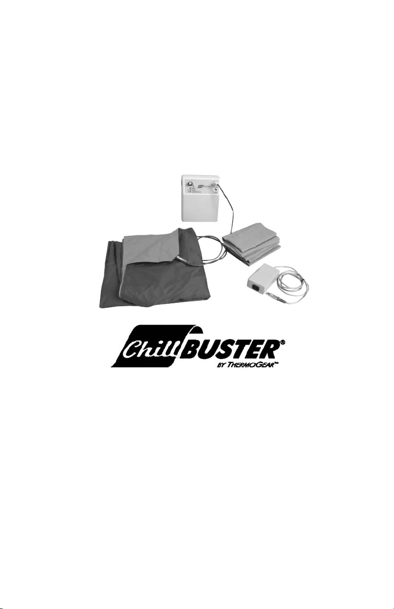
FEATURES
______________________________________________________
The ChillBuster
®
Model 8000 Series Portable Electric
Blanket System has three basic elements, plus accessories
and supplies.
BLANKET AND COVER
The blanket, which is placed over the patient, has a cable
to connect to the Controller. A disposable, sterile cover
is to be used over the blanket with each use, to avoid
cross-contamination risk.
CONTROLLER
The Controller, with an internal battery, provides the ONOFF and temperature adjustment control, and status
indicators. An optional bracket allows suspending the
controller from a bed rail or an IV pole.
The adjustment knob clicks to the OFF position when
rotated in a fully counter-clockwise direction. No power
will be applied to the blanket in this condition.
When the adjustment is clicked ON by rotating the knob
clockwise, direct current electrical energy is applied to
the blanket to provide heating. The temperature setting
is determined by the amount of knob rotation.
Three indicators are provided to show status of the
Controller, as described below. An audible alert is
provided and operates in conjunction with one of the
indicators.
POWER Indicator
The POWER INDICATOR is illuminated when the knob on
the controller is rotated to the right of the detented OFF
position and power is applied to the blanket. It is
illuminated when the Power Supply is in use, which
Page 9

allows the unit to operate while charging the battery or
when operating from a battery.
The indicator will not illuminate if the battery charger is
in use or when the battery is depleted.
CHARGE Indicator
The CHARGE INDICATOR is illuminated when the
Controller is connected to a source of power using the
battery charger, the AC POWER MODULE, or a DC power
cord, indicating that the internal battery is being
charged. The indicator remains lighted when a full
charge has been obtained. Once the external power
supply has been disconnected, the CHARGE INDICATOR
will no longer be illuminated.
LOW BATTERY/FAULT Indicator
The LOW BATTERY/FAULT INDICATOR is illuminated
when an internal or external fault is detected, or if the
internal battery becomes sufficiently depleted. The
audible alert will also be sounding when this indicator is
illuminated.
POWER SUPPLIES
Depending upon the specific model ordered, there are
two external line-voltage power supplies that are
available. One supply, the battery charger, is used only
to recharge the internal battery, but not while the
blanket is in use. The second supply, the AC power
module, may be used at any time, when line power is
available, to recharge the internal controller battery
and/or to provide power for operation of the blanket.
A DC cord may also be provided for connection to an
automotive "cigarette lighter" socket. The DC cord
allows the blanket to operate while charging the battery.
Page 10

Battery Charger
The BATTERY CHARGER is a small rectangular unit with
an integral AC plug for directly connecting to the AC
line wall outlet power. An integral cable and connector
attaches to the POWER INPUT/CHARGER socket on the
Controller. This charger provides current to recharge the
internal Controller battery, but does not provide power
for the blanket. The blanket will not heat while this
Battery Charger is in use.
AC Power Module
The AC POWER MODULE is larger than the battery
charger, described above. The AC Power Module is
capable of providing power to the controller for blanket
operation while simultaneously re-charging the internal
battery. A detachable hospital-grade AC power cord
connects the AC POWER MODULE to the wall outlet. An
integral cable and connector attaches to the POWER
INPUT CHARGER socket on the Controller.
DC Cord (for 12 Volt operation)
A power cord with a cigarette lighter adapter is available
for operation from an external DC power source. The DC
power source must be nominal 12 volts, such as is found
in current production automobiles.
The DC cord allows the blanket to operate while
charging the battery.
ACCESSORIES/SUPPLIES
Rail Hook
The ChillBuster®8000 System is supplied with a hook to
allow the Controller to be suspended from a bed rail.
This rail hook may be removed, and replaced with a flat
plate, to facilitate use of the controller on flat surfaces.
Page 11

An optional bracket allows the Controller to be attached
to an IV pole.
Carrying Bag
A carrying bag is provided as an accessory, to allow
convenient organization of the blanket, blanket covers,
the Controller, and one or more power supplies, as
desired.
Disposable, Sterile Blanket Cover
A disposable blanket cover is supplied in a sterile
condition. The cover should be replaced between
patients, to avoid risk of cross-contamination by contact
with body fluids.
Page 12

Page 13

OPERATION
______________________________________________________
The ChillBuster
®
Model 8000 Series Portable Electric
Blanket System is typically packed in the carrying bag.
The following steps provide simple instructions for using
the System.
Beginning Use With a Patient
1. Determine the optimum means of powering the
blanket for the specific patient need. The choices are
internal battery power only, external DC power, or
external AC power. Determine that an external DC or
AC power source is available, or use the internal
battery power. If an AC power source is to be used,
connect the AC power cord to the module.
Be sure that the power cord will reach the selected
power source.
2. Place the Controller in a convenient, stable location.
The Controller must be protected from fluids and
from being dropped. Be sure that the controller knob
is in the OFF position by turning the ON-OFF knob
fully counter-clockwise, past the detent, to the OFF
position. Locate the blanket cable, and route to the
patient. Note that the cable should route to either
the right foot or left shoulder of a patient lying on
his/her back, to facilitate connection to the blanket.
3. Locate the blanket and a disposable, sterile blanket
cover. Place the blanket cover over the blanket,
making certain that the connector on the blanket is
located at the open end of the cover. Connect the
blanket connector to the cable from the Controller.
4. Remove the covering of the tape on the blanket
cover, and seal the cover closed.
Page 14

5. Place the blanket over the patient with the blue side
of the blanket away from the patient.
6. If it has been determined that an external power
source is to be used, connect the cable from the
cigarette lighter adapter or the AC Power Module to
the Controller. Then plug the lighter adapter into the
cigarette lighter socket or the AC power cord into the
wall outlet. At this point, the CHARGE indicator will
be illuminated.
7. Once the connections have been made, turn the
Controller knob clock-wise, past the detent (a click
may be heard). Adjust the knob to obtain the desired
heating. Highest heat will be at the fully clock-wise
point. The POWER indicator should be illuminated.
8. Monitor the patient's temperature and other vital
signs. Position the temperature setting, as necessary.
Removing From Use With a Patient
1. Turn the temperature adjustment knob fully counter-
clockwise. A click may be heard and the POWER
indicator should no longer be illuminated.
2. Remove the blanket from the patient. Disconnect the
cable from the blanket.
3. Remove and discard the blanket cover. If bodily fluids
have contacted the blanket cover, aseptic technique
should be used to discard the cover and to clean the
blanket.
4. Disconnect the power supply (if used).
5. Re-pack the ChillBuster
®
8000 System components into
the carry bag.
Page 15

6. Determine if another blanket cover is available in the
carry bag. If not, obtain another blanket cover(s) and
re-stock the carry bag.
Recharging The Battery
1. Connect any one of the three power supply
accessories to the controller (cigarette lighter adapter,
battery charger, or AC Power Module).
2. Connect the accessory to a power source.
3. Maintain the power source connection and allow the
Controller to charge. For best results, allow at least 8
hours for full charge.
4. Disconnect the power supply accessory from the
power source and from the Controller.
Page 16

ALARMS
______________________________________________________
During use, the ChillBuster
®
8000 System monitors several
conditions. If necessary, an audible and a visual alert are
provide to the user. The audible alert will pulse, to draw
the user's attention.
Suggested responses to alarm conditions are shown
below:
When an alarm occurs, first check the patient. Then note
the indicators, determining which are illuminated. Turn
the temperature adjustment control to the OFF position.
The audible alarm should cease.
Determine if a high heat condition seems to exist,
indicating that an over-temperature condition has been
detected. A high temperature condition may be
normal, if the ambient temperature is high, or if the
patient has had an additional covering to reduce heat
loss. After the patient and blanket have cooled, the
controller can be re-set to a lower control point, or the
use of the blanket may be discontinued.
Check for proper connections. A loose connection to the
blanket may trigger a combined audible alarm and
illuminated FAULT indicator.
If the ChillBuster
®
System is being operated only from
the internal battery, a low battery indication will result
in an audible alert. The POWER and CHARGE indicators
will not be lit, but the FAULT indicator will be
illuminated. Recharge the battery using the battery
charger, or use the AC POWER MODULE with the
Controller.
Page 17

If the alarm is not due to the above conditions, then
suspect a system fault.
Remove the blanket from the patient. Keep the patient
warm using alternative techniques.
At a convenient time, re-check the blanket operation, by
testing the blanket temperature at various adjustment
settings. If the blanket does not heat or if the
temperature is not stable and controlled, return the
System and the blanket for repair.
Page 18

Page 19

CARE AND MAINTENANCE
______________________________________________________
CLEANING
The ChillBuster
®
8000 System components should be
cleaned according to the procedures described below,
using only the cleaning material specified. While
cleaning, carefully check for worn or damaged cables.
Timely maintenance will avoid problems.
Wipe down exterior surfaces of the Controller with a
slightly-damp cloth containing a mild cleaning agent
such as 409. Do not use an excessively wet cloth or a
spray cleaner, to avoid ingress of liquids.
Use another cloth, dampened only with water, to remove
the residue of the cleaning agent.
The blanket may be cleaned by machine washing in warm
water using a household detergent (no bleach), and a
gentle wash cycle; tumble dry on low heat, or air dry.
MAINTENANCE
The ChillBuster
®
8000 System has no user-serviceable
components. If a question arises as to proper
functioning, the System may be checked by using an
external thermometer (not supplied) to monitor the
heating action.
Fully Recharge the Internal Battery
Check the Controller temperature adjustment knob, to
ensure that it is in the fully counter-clockwise position.
Verify this by turning to the right, and back to the left,
past the click/detent. Then attach any one of the three
possible external power sources, as described above.
Verify that the CHARGE indicator is illuminated. Allow
the System to charge fully for at least 12 hours for a full
charge. Remove the external cable. The CHARGE
indicator should no longer be illuminated.
Page 20

Temperature Control Check
(ambient temperature must be less than 77 degrees F
(30 degrees C))
1. Set up the blanket. Spread the blanket (with or
without a blanket cover) over a flat surface, such as a
mattress with the blue-colored side of the blanket up.
Connect the controller to the blanket.
2. Make an initial temperature measurement. Using an
external thermometer, measure the temperature
immediately below the blanket, in the middle of the
covered area. Note the result. If this temperature is
above 86 degrees F (25 degrees C), discontinue this
test until a lower ambient temperature is available.
3. Turn the Controller adjustment knob fully clock-wise.
The POWER indicator should be illuminated. Note the
time. After a minimum of 10 minutes, record another
measurement of the temperature in the same manner
as above.
4. Turn the Controller knob counter-clockwise, until
resistance is felt. Do not turn to the full OFF position.
The POWER indicator should still be illuminated.
Note the time. After a minimum of 10 minutes,
record another measurement of the temperature in
the same manner as above.
5. Review the temperature results. The temperature in
step 2 should be no more than 77 degrees F (25
degrees C). The temperature in step 3 should be
higher than the temperature in step 2, but less than
108 degrees F (42 degrees C). The temperature in
step 4 should be higher than the temperature in step
2, and lower than the temperature in step 3.
Page 21

If the readings are out of range, the unit may require
servicing. Refer to the notes before contacting
ThermoGear
TM
for more information.
INTERNAL BATTERY
The ChillBuster
®
8000 System uses a sealed lead acid
battery. The battery will provide many years of service.
However, if the battery is not maintained with a proper
charge, or with the passage of time, it may require
replacement.
Battery Replacement
Open the access panel on the bottom of the Controller
using a suitable screwdriver. Separate the connection to
the battery, and remove the battery. Replace the battery
only with a new battery of identical type, obtained from
ThermoGear
TM
. Fully charge the new battery before
returning the System to service.
Temp.
Measurement
Step
2
Step
3
Step
4
Acceptable
range
If temp. is too high, testing will be
invalid. Seek a cooler location.
If the temp. does not increase,
check the blanket and connections.
If the temp. is out of range, check
blanket and connections.
20 C to
25 C
35 C to
42 C
between
step 2
& step 3
OK? Note
Page 22

Page 23

SERVICE AND WARRANTY
______________________________________________________
CUSTOMER SERVICE
For general information, questions about products,
orders and after-sales support, call ThermoGear
TM
Customer Service. Contact information is provided inside
the front cover.
Technical inquiries about the ChillBuster
®
Model 8000
Series System should also be directed to ThermoGear
TM
Customer Service.
WARRANTY and REPAIR SERVICE
If a repair seems to be necessary, call ThermoGear
TM
Customer Service first. The contact information is
provided inside the front cover. You may be directed to
a designated facility closer to you. Before returning any
product, a Returned Goods Authorization (RGA) will be
provided to you, with shipping instructions for the
proper repair facility. Do not return product without
obtaining an RGA.
Warranty repairs will be provided at no charge. Out of
warranty repairs will be quoted upon request.
Page 24

Page 25

LIMITED WARRANTY
ThermoGearTMChillBuster®8000 Systems are warranted
against defective material and workmanship (excluding
battery, cables, and blanket) for one year following the
delivery of the System to the original purchaser.
If, in the judgment of ThermoGear
TM
, any System or part
thereof is proven to be defective in material or
workmanship within one year from date of original
purchase, such defect(s) will be repaired or replaced (at
the option of ThermoGear
TM
) free of charge for parts or
labor
This warranty does not apply to any product which has
been damaged by accident, or which has been misused,
abused, altered, or repaired by anyone other than
ThermoGear
TM
or its authorized representatives.
ThermoGear
TM
shall not be liable to any person for any
direct or consequential damages resulting from or
caused by any defect, failure, or malfunction of this
System.
This warranty is in lieu of all other warranties expressed
or implied including any implied warranty of
merchantability or fitness for a particular purpose, and
no person is authorized to assume for ThermoGear
TM
any
other liability in connection with the sale of this System.
To obtain service, the System or component should be
shipped pre-paid, with the Return Goods Authorization,
to ThermoGear
TM
, at the address provided by Customer
Service. In-warranty repairs will be returned postage
pre-paid.
Page 26

Page 27

SUPPLIES, PART AND ACCESSORIES
______________________________________________________
CONSUMABLES
Sterile Blanket Cover (25 covers/box) p/n 800ZAC-25
PARTS
Blanket p/n C90016R
Battery (sealed lead-acid) p/n C90007R
Carry Bag p/n C90028B (black)
p/n C90028O (orange)
Manual p/n C90022
ACCESSORIES
AC Power Module p/n C90011AR
(powers blanket and re-charges battery)
AC Battery Charger p/n C90023R
(re-charges battery, only)
Cigarette Lighter Adapter p/n C90024R
(powers blanket and re-charges battery)
Contact ThermoGear
TM
at the address listed inside the
front cover for ordering information and prices.
Page 28

Page 29

SYMBOLS AND DEFINITIONS
______________________________________________________
DEFINITIONS
“ATTENTION”: CONSULT ACCOMPANYING DOCUMENTS
COVER PATIENT FULLY
DO NOT PARTIALLY COVER
DO NOT FOLD
TYPE BF
FOR CLASS II EQUIPMENT
THIS PRODUCT HAS BEEN CERTIFIED TO BOTH
US AND CANADIAN REQUIREMENTS
!
Page 30

Page 31

SPECIFICATIONS AND DECLARATIONS
______________________________________________________
NOTE. Product design and specifications are
subject to change without notice.
Detailed Specifications
Controller Dimensions - 13"(l) x 8"(w) x 10.5"(h)
Controller Weight - 8 lbs, with battery included
Blanket - Size: 40 x 60 inches (102 x 152 cm)
- materials: outer layer waterproof nylon
inner layer nylon acrylic
Blanket Cover - Size: 40 x 60 inches (102 x 152 cm)
- supplied as sterile, for single-use
- moisture-resistant polypropylene
Temperature Specs. - low setting approx. 30 C
high setting approx. 40 C
- thermal cutoff: 106F (41C)
Operating temperature - -4F to +104F (-20 to +40C)
(ambient)
Shipping/storage temp. - -22F to + 122F (-30C to +50C)
Humidity - 10% to 95% RH (non-condensing) @ 35C
Battery capacity - 7Ah
Battery Voltage - 8.5 to 14.5 Volts.
Supply Voltage - 8.5 to 16 Volts
Supply Current - 3 to 6.5 Amps
Recharging time (using - less than 12 hours
specified AC charger)
Battery operation time - approximately 4.4 hours (lowest setting)
- approximately 1.3 hours (highest setting)
Battery lifetime - approximately 150 recharging cycles
Cigarette lighter adapter - 10A fuse
AC battery charger - wall bug (transformer plugs into
AC outlet)
- output 15V, 1A
AC Power Module - input 110 to 240 VAC, 50-60 Hz.
- European Classification Type B
Carrying Bag - nylon material
Classification - European Classification: Type B
IPXO - not rated for water ingress
Page 32

Page 33

Page 34

Page 35

 Loading...