

NEC versa 2600 schematic

SOLD BY laptopia2005 DO NOT RESELL!!
NEC Versa 2600 Series
Service Guide
Art Copy Version
SOLD BY laptopia2005 DO NOT RESELL!!

SOLD BY laptopia2005 DO NOT RESELL!!
PROPRIETARY NOTICE AND LIABILITY DISCLAIMER
The info rmat ion disclos ed in t his do cument , inclu ding all designs and r elat ed materials, is
the valuable property of NEC Computer Systems Division, Packard Bell NEC, Inc.
(NECCSD, P BNEC) and/or its licensors. NECCS D and/or its licensors, as appro priate, reserve all pat ent, copyright and other proprietary rights to this document, including all design, manufacturing, reproduction, use, and sales rights thereto, except to the extent said
rights are expressly granted to others.
The NECCSD product(s) discussed in this do cument are warrant ed in accordance with the
terms of the Warranty Statement accompanying each product. However, actual
performance of each such product is dependent upon factor s such as system configuration,
customer data, and operator control. Since implementation by customers of each product
may vary, the suitability of specific product configurations and applications must be
determined by the customer and is not warranted by NECCSD.
To allow for design and specification impro vement s, t he information in this do cument is
subject to change at any time, without not ice. Reproduct io n of this document or po rtions
thereof without prior written approval of NECCSD is prohibited.
NEC is a registered trademark of NEC Corporation;
Versa is a U.S. registered trademark of NEC Technologies, Inc.;
all are used under license by NEC Computer Systems Division (NECCSD), Packard Bell NEC, Inc.
All other product, brand, or trade names used in this publication are the trademarks or registered
trademarks of their respective trademark owners.
First Printing — May 1997
Copyright 1997
NEC Computer Systems Division, Packard Bell NEC, Inc.
1414 Massachusetts Avenue
Boxborough, MA 01719
All Rights Reserved
SOLD BY laptopia2005 DO NOT RESELL!!

SOLD BY laptopia2005 DO NOT RESELL!!
Contents
Preface......................................................................................................................... ix
Abbreviations............................................................................................................... xi
Section 1 Technical Information
Hardware Overview — Front.......................................................................................1-2
Liquid Crystal Display (LCD)................................................................................1-2
Power Button .......................................................................................................1-4
Power and Status LEDs........................................................................................1-4
Keyboard..............................................................................................................1-5
NEC VersaGlide...................................................................................................1-5
CD-ROM Reader and Diskette Drive....................................................................1-6
iii
Hardware Overview — Right Side...............................................................................1-6
PC Card Slots.......................................................................................................1-7
Kensington Lock...................................................................................................1-7
Hardware Overview — Left Side.................................................................................1-7
Hardware Overview — Rear........................................................................................1-8
Infrared Port.........................................................................................................1-8
Keyboard/Mouse Port...........................................................................................1-8
Expansion Port .....................................................................................................1-8
Monito r (Video) Port............................................................................................1-8
Parallel Port (LPT1)..............................................................................................1-8
Serial Port (COM1) ..............................................................................................1-9
AC/DC Power Port...............................................................................................1-9
Hardware Overview — Internal Component s...............................................................1-9
Battery Pack.........................................................................................................1-9
Hard Disk Drive....................................................................................................1-10
Diskette Drive.......................................................................................................1-10
10x CD-ROM Reader...........................................................................................1-10
CPU Board...........................................................................................................1-11
Sound Board.........................................................................................................1-12
I/O Board.............................................................................................................1-13
Bridge Battery......................................................................................................1-13
System Memory...........................................................................................................1-14
Memo ry Map........................................................................................................1-14
System Video...............................................................................................................1-15
SOLD BY laptopia2005 DO NOT RESELL!!

SOLD BY laptopia2005 DO NOT RESELL!!
iv Contents
Parallel Interface..........................................................................................................1-15
Serial Interface.............................................................................................................1-16
NEC Versa Chip Set....................................................................................................1-16
Intel Pentium P55CLM Microprocessor................................................................1-16
256K X Flash ROM..............................................................................................1-16
ROM BIOS....................................................................................................1-17
VGA Controller....................................................................................................1-17
Keyboard Controller .............................................................................................1-18
PC Card Controller...............................................................................................1-18
Sound Int egrated Circuit .......................................................................................1-18
Interrupt Controllers .............................................................................................1-19
Power Management Overview .....................................................................................1-20
System Power Management..................................................................................1-21
Local Power Management.....................................................................................1-21
Plug and Play...............................................................................................................1-21
Specifications...............................................................................................................1-22
Section 2 Setup and Operation
Unpacking the System..................................................................................................2-1
Hardware Setup...........................................................................................................2-1
Cable Connections................................................................................................2-3
Power Sources.............................................................................................................2-4
Using the AC Adapter...........................................................................................2-4
Using the Main Battery Pack.................................................................................2-5
In stallin g the Batt ery Pack..............................................................................2-5
How to Recharge the Battery Pack.................................................................2-6
Battery Handling...................................................................................................2-6
Replacing the Battery Pack ............................................................................2-7
Battery Life...........................................................................................................2-8
Extending Battery Life...................................................................................2-8
Battery Charging............................................................................................2-9
Batter y Precaut ions........................................................................................ 2-9
Battery Disposal.............................................................................................2-10
Internal Batteries...................................................................................................2-10
Extending Battery Life..........................................................................................2-10
Operating Controls ......................................................................................................2-11
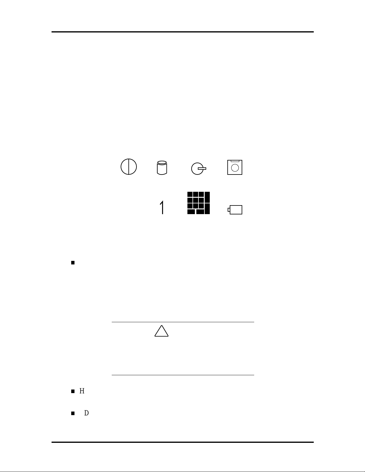
Status Icons and LEDs..........................................................................................2-12
SOLD BY laptopia2005 DO NOT RESELL!!

SOLD BY laptopia2005 DO NOT RESELL!!
Status Icons...................................................................................................2-12
Function Keys (Fn Keys).......................................................................................2-13
Updating the System BIOS............................................................................2-13
Power-On Self -Test (POST).......................................................................................2-14
POST Errors.........................................................................................................2-15
Setup Utility ................................................................................................................ 2-16
Setup Utility..........................................................................................................2-17
How to Enter Setup.......................................................................................2-17
How to Use Setup..........................................................................................2-17
The Setup Screen...........................................................................................2-17
Using Keys ........................................................................................................... 2-18
Checking/Setting System Parameters..............................................................2-19
Using Power Management ....................................................................................2-25
Contents v
Power Saving Modes.....................................................................................2-25
Power Management Settings..........................................................................2-26
Using Fn-F3...................................................................................................2-26
Section 3 Troubleshooting
Quick Troubleshooting................................................................................................3-1
Helpful Questions ........................................................................................................3-4
Section 4 Field Service Guidelines
Preventive Maintenance...............................................................................................4-1
Cleaning the Notebook Exterior............................................................................4-2
Cleaning the Notebook Interior.............................................................................4-2
Protecting the Disk Drives ....................................................................................4-2
Handling the Battery Packs...................................................................................4-3
Maintaining the LCD Quality................................................................................4-3
Disassembly and Reassembly........................................................................................4-4
Required Tools and Equipment ............................................................................4-5
Battery Pack.........................................................................................................4-5
Hard Disk Drive....................................................................................................4-6
Keyboard..............................................................................................................4-7
Heat Shield and CPU Board ..................................................................................4-9
LCD and Top Cover.............................................................................................4-11
VersaGlide Assembly............................................................................................4-13
Sound Board.........................................................................................................4-14
SOLD BY laptopia2005 DO NOT RESELL!!

SOLD BY laptopia2005 DO NOT RESELL!!
vi Contents
LED Status Board and IR Board...........................................................................4-14
10X CD-ROM Reader and Heat Shield.................................................................4-14
Bridge Battery and Diskette and Hard Drive Connector Board..............................4-16
Diskette Drive.......................................................................................................4-17
Power Board.........................................................................................................4-18
Main Board...........................................................................................................4-18
Reassembly .......................................................................................................... 4-18
Illustrated Parts Breakdown.........................................................................................4-18
Service Information......................................................................................................4-22
Technical Suppo rt........................................................................................................4-22
Product Information.....................................................................................................4-23
Ordering Information from FaxFlash............................................................................4-23
Appendix A Connector Locations and Pin Assignments
Appendix B Video Modes
List of Figures
1-1 NEC Versa 2600 Series Notebook................................................................. 1-1
1-2 Front View..................................................................................................... 1-3
1-3 Keybo ard Layout ........................................................................................... 1-5
1-4 VersaGlide Location...................................................................................... 1-6
1-5 Right Side Features........................................................................................ 1-6
1-6 Left Side Features.......................................................................................... 1-7
1-7 Rear Features................................................................................................. 1-8
1-8 CPU Board Layout........................................................................................ 1-11
1-9 Sound Board Layout...................................................................................... 1-12
1-10 I/O Board ...................................................................................................... 1-13
2-1 AC Adapter ................................................................................................... 2-1
2-2 Powering On the System ................................................................................ 2-2
2-3 Power and I/O Connector Locatio ns .............................................................. 2-3
2-4 NEC Versa AC Adapter................................................................................. 2-4
2-5 Battery Release Latch ................................................................................... 2-7
2-6 Inserting Battery Pack.................................................................................... 2-8
2-7 Panel LEDs and Controls............................................................................... 2-11
SOLD BY laptopia2005 DO NOT RESELL!!

SOLD BY laptopia2005 DO NOT RESELL!!
2-8 Status Icons................................................................................................... 2-12
4-1 Releasing the Battery Pack............................................................................. 4-5
4-2 Removing the Hard Disk Drive (Step1).......................................................... 4-6
4-3 Removing the Hard Disk Drive (Step 2)......................................................... 4-6
4-4 Removing the Hard Disk Drive (Step 3)......................................................... 4-7
4-5 Removing the Keyboard................................................................................. 4-8
4-6 Removing the Heat Sink/Shield Subassembly ................................................. 4-9
4-7 Removing the CPU Board.............................................................................. 4-10
4-8 Removing the LCD Assembly (Step 1)........................................................... 4-11
4-9 Removing the LCD Assembly (Step 2)........................................................... 4-12
4-10 Disconnecting VersaGlide Cables................................................................... 4-13
4-11 Remo ving the CD-ROM Reader..................................................................... 4-15
Contents vii
4-12 Remo ving the CD-ROM Reader Assembly Screws......................................... 4-15
4-13 Removing the Bridge Battery and Diskette and Hard Drive Connector Board. 4-17
4-14 NEC Versa 2600 Series Illustrated Parts Breakdown...................................... 4-19
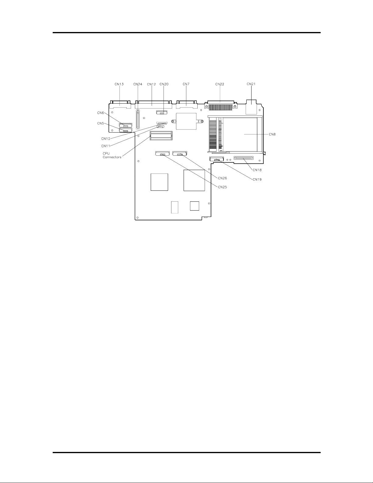
A-1 CPU Board Layout ........................................................................................ A-1
A-2 Main Board Layout........................................................................................ A-2
A-3 Sound Board Layout ...................................................................................... A-3
List of Tables
1-1 Model Configurations NEC Versa 2600 Series............................................... 1-2
1-2 Memory Map................................................................................................. 1-14
1-3 NEC Versa 2600 Series Chip Types and Technologies ................................... 1-16
1-4 Interrupt Controllers...................................................................................... 1-19
1-5 DMA Channel................................................................................................ 1-20
1-6 Automatic Power-Saving Features ................................................................. 1-20
1-7 Specificatio ns................................................................................................. 1-22
2-1 I/O Connector Descriptions............................................................................ 2-3
2-2 Control and Switch Functions ........................................................................ 2-11
2-3 Fn Key Operatio ns......................................................................................... 2-13
2-4 POST Error Messages.................................................................................... 2-15
2-5 Setup Key Functions...................................................................................... 2-18
2-6 Setup Parameters........................................................................................... 2-19
2-7 Automatic Power-Saving Features ................................................................. 2-26
SOLD BY laptopia2005 DO NOT RESELL!!

SOLD BY laptopia2005 DO NOT RESELL!!
viii Contents
3-1 Quick Troubleshooting................................................................................... 3-1
4-1 NEC Versa 2600 Series Disassembly Sequence.............................................. 4-4
4-2 NEC Versa 2600 Series Field-Replaceable Parts............................................. 4-20
4-3 NEC Service and Information Telephone Numbers......................................... 4-22
A-1 CPU Board Connector................................................................................... A-1
A-2 Main Board Connectors ................................................................................. A-2
A-3 Sound Board Connectors............................................................................... A-3
A-4 Keyboard/Mouse Connectors......................................................................... A-3
A-5 Serial Po rt Connector Pin Assignments .......................................................... A-4
A-6 CRT Connector Pin Assignments................................................................... A-4
A-7 Parallel Printer Pin Assignments..................................................................... A-5
A-8 Power Connector........................................................................................... A-5
A-9 Hard Disk Drive Connector............................................................................ A-6
B-1 LCD Display Mo de Setting (800x600 TFT Color LCD
and Simultaneous CRT Display)..................................................................... B-1
B-2 CRT Display Mode (CRT Only)..................................................................... B-3
B-3 Panning Video Mode (800x600 TFT Color LCD and
Simultaneous CRT Display) ........................................................................... B-4
SOLD BY laptopia2005 DO NOT RESELL!!
SOLD BY laptopia2005 DO NOT RESELL!!
Preface
This service and reference manual contains the technical information necessary to set up and
maintain the following NEC Versa® 2600 Series models:
NEC Versa 2630CD
NEC Versa 2635CD
NEC Versa 2650CD
NEC Versa 2655CD
NEC Versa 2650CDT
NEC Versa 2655CDT.
ix
The manual also provides hardware and interface information for users who need an overview of the system design. The manual is written for NEC-trained customer engineers, system analysts, service center personnel, and dealers.
The manual is organized as follows:
Section 1 Technical Information, provides an overview of the hardware and interface
components. System specifications are listed including computer dimensions, weight, environment, safety compliance, power consumption, and system memory specifications.
Section 2 Setup and Operation, takes the authorized service technician or dealer from
unpacking to setup and operation. The section includes a description of operating controls,
setting parameters and accessing the NECCSD bulletin board system (BBS).
Section 3 Troubleshooting, lists troubleshooting procedures as well as helpful
servicing hints.
Section 4 Field Service Guidelines, provides disassembly and assembly procedures,
and an exploded-view diagram of the NEC Versa system with part numbers.
Appendix A Connector Locations and Pin Assignments, provides a list of the main
board internal connector pin assignments and a list of external pin assignments.
Appendix B Video Modes, lists NEC Versa supported video modes.
An Index is included for convenience.
SOLD BY laptopia2005 DO NOT RESELL!!
SOLD BY laptopia2005 DO NOT RESELL!!
Section 1
Technical Information
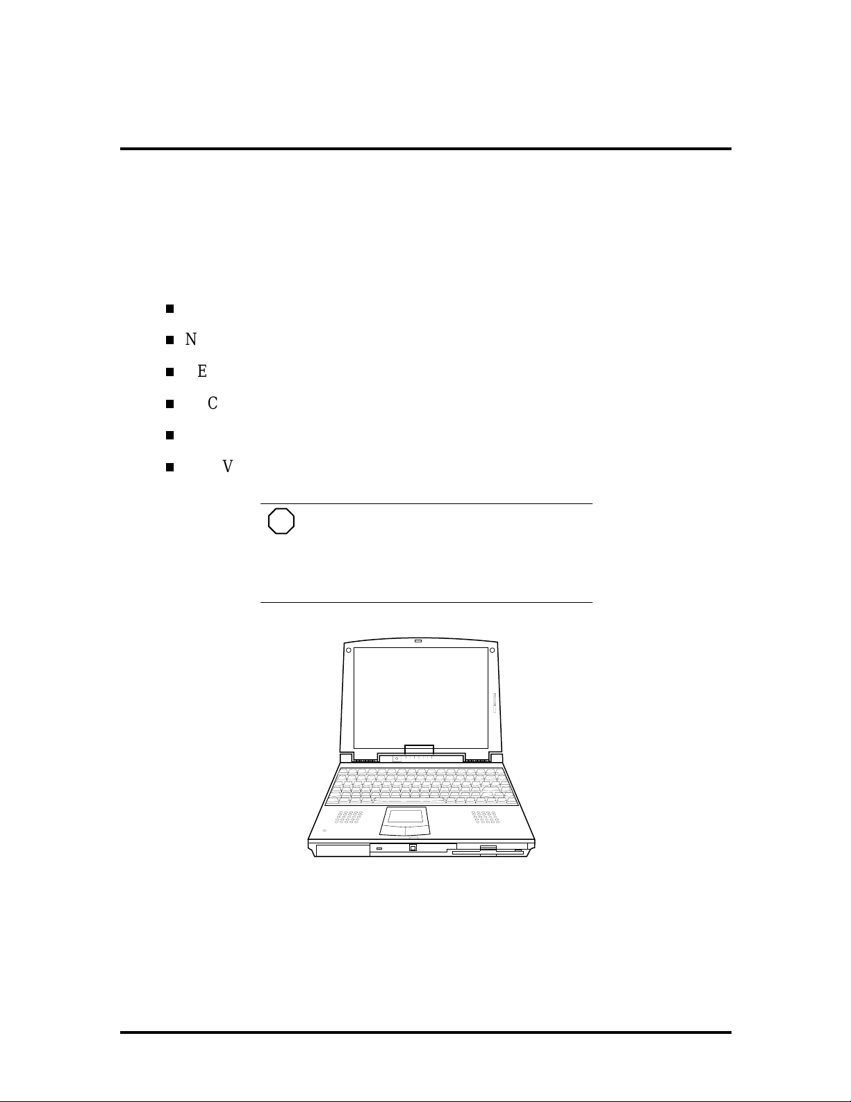
The NEC Versa 2600 Series notebook co mputers are lightweight, compact, and fully I BM
compatible. T he latest additions to t he NEC Versa 2600 fa mily include the follow ing
mo de ls:
NEC Versa 2630CD
NEC Versa 2635CD
NEC Versa 2650CD
NEC Versa 2655CD
NEC Versa 2650CDT
NEC Versa 2655CDT.
NOTE
This service manual covers the NEC
Versa 2630CD, 2635CD, 2650CD, 2655CD,
2650CDT, and 2655CDT models only. All figures in this manual reflect these models.
Figure Section 1-1 NEC Versa 2600 Series Notebook
This section of the manual provides system configuration information, including an overview of hardware and interface components. See the following table for a system specific
breakdown of each model’s hardware.
SOLD BY laptopia2005 DO NOT RESELL!!
SOLD BY laptopia2005 DO NOT RESELL!!
1-2 Technical Information
Table Section 1-1 Model Configurations NEC Versa 2600 Series
Feature 2630CD 2635CD 2650CD 2655CD 2650CDT 2655CDT
CPU (Pent ium) P54CSLM
133 MHz
On-Boar d RA M 16 MB 16 MB 16 MB 16 M B 16 MB 16 MB
Video M emory 1.5 MB 1.5 MB 1.5 MB 1.5 MB 1 MB 1 MB
Hard Disk Driv e 1.44 GB 1.44 GB 1.44 GB 1.44 GB 1.44 GB 1.44 GB
CD-ROM Reader 10X 10X 10X 10X 10X 10X
Color LCD ( 12.1”) SVGA1,
DSTN
Battery NiMH NiMH NiMH NiMH LiIon LiIon
1. Super VGA (SVGA) color displa y
2. Dualscan Super-Twisted Nematic (DSTN)
.
Thin Film Transist or (TFT)
3
2
P55CSLM
133 MHz
SVGA1,
2
DSTN
P55CL,
150 MMX
SVGA1,
2
DSTN
P55CL,
150 MMX
SVGA1,
2
DSTN
P55CL,
150 MMX
SVGA1,
3
TFT
P55CL,
150 MMX
SVGA1,
3
TFT
HARDWARE OVERVIEW—FRONT
Take a moment to be come familiar w ith th e locatio n and fu nction of co nt rols located on th e
front of the system.
Liquid Crystal Display (LCD)
The LCD operates with the Chips & Technologies 65550B VGA controller. The contro ller
supports Super VGA, uses a 64 bit accelerator with a Peripheral Component Interco nnect
(PCI) interface. The LCD also supports VE S A t iming.
The NEC Versa 2630CD, 26535CD, 2650CD and 2655CD LCD features the following:
12.1-inch Dual- STN, Cold Cathode Fluorescent Tube (CCFT) S uper VGA color
LCD
0.30 mm dot pitch
16-bit digital interface
800 x 600 resolution
64,000 colors
Slide bar that adjust screen co ntrast.
The NEC Versa 2650CDT and 2655CDT features the following:
12. 1-inch active -ma trix Thin Film T ra nsis tor ( TF T), Su pe r VGA (SVGA) ba ck lit
color LCD
0.3 mm dot pitch
SOLD BY laptopia2005 DO NOT RESELL!!
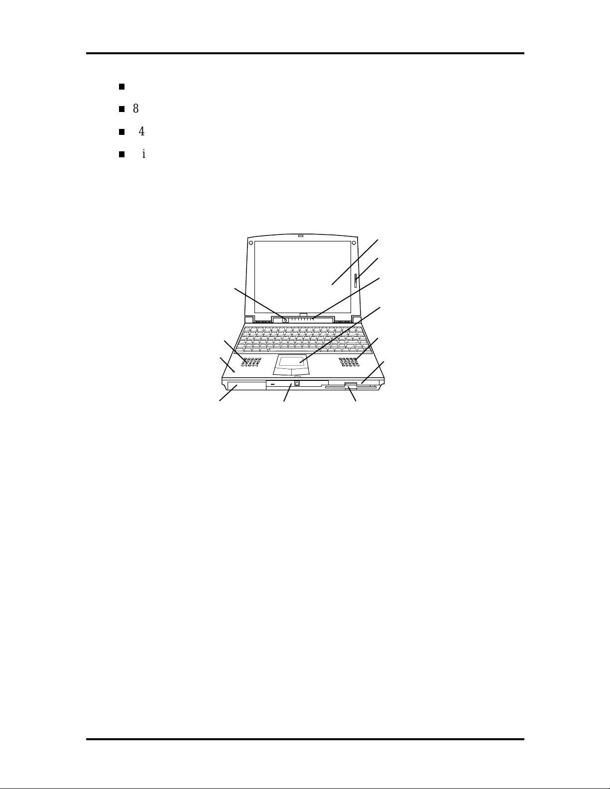
SOLD BY laptopia2005 DO NOT RESELL!!
18-bit digital interface
800 x 600 resolution
64,000 colors
Slide bar that adjust screen brightness.
Additional LCD panel features include a slide switch which contro ls adjusts screen brightness.
Technical Information 1-3
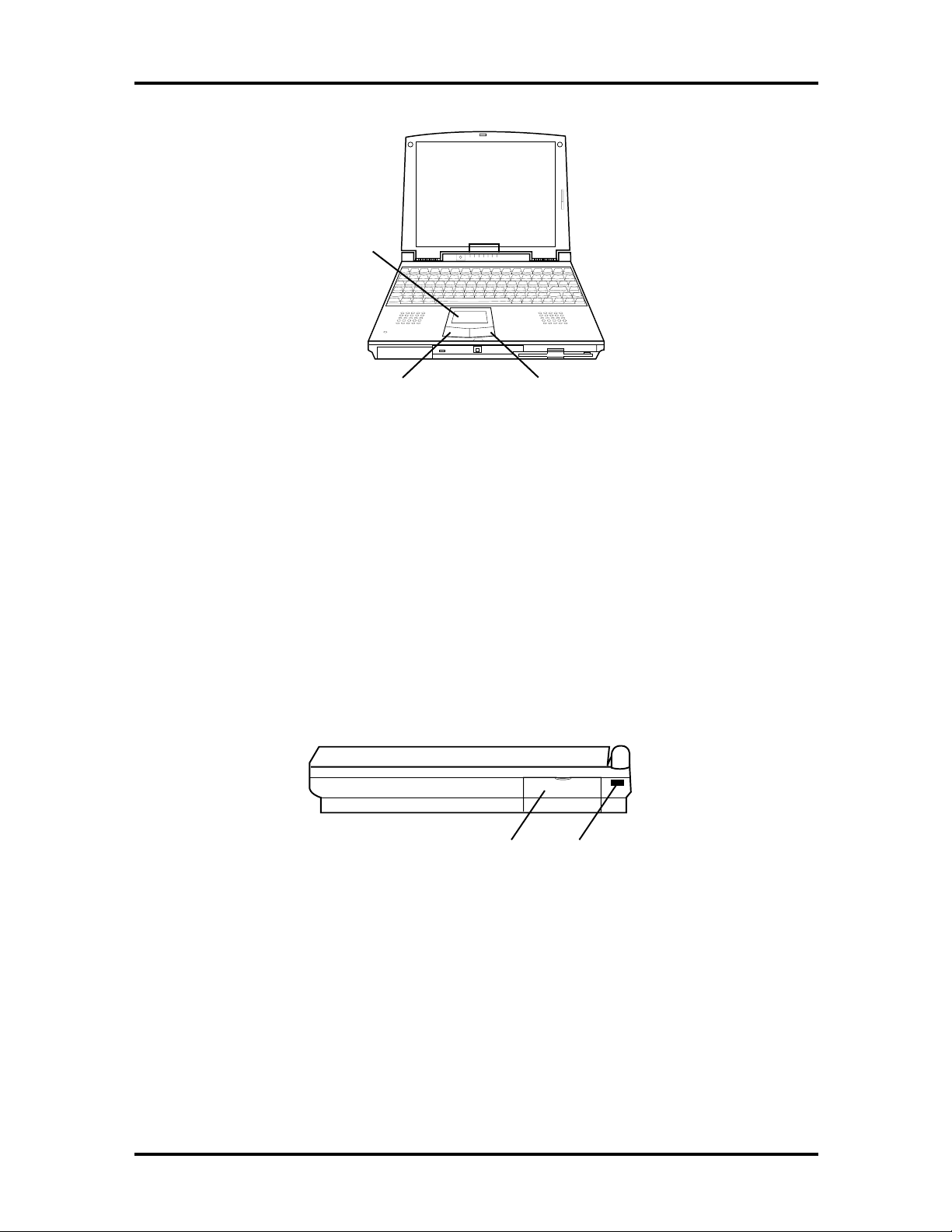
LCD Panel
LCD Slide Bar
Status
LEDs
VersaGlide
SpeakerSpeaker
Hard Drive
Diskette Drive
Microphone
Power
Button
Battery Bay
NEC
CD-ROM Reader
Figure Section 1 -2 Front View
Another video feature includes a CRT port o n t he system's rear panel that allows the user to
connect an opt ional monochrome or color external display to the system. The computer can
support the LCD and external display simultaneously.
SOLD BY laptopia2005 DO NOT RESELL!!
SOLD BY laptopia2005 DO NOT RESELL!!
1-4 Technical Information
Power Button
Press the power butt on to po wer on and power off the computer. The power button is a
“smart” switch, meaning that it recognizes when the system is in Suspend mode. If in Suspend mode, you cannot po wer off until you press the power button again to bring the system out o f Suspend mode, then you are able to power off.
Power and Status LEDs
The Power and St atus LEDs are situated r ight below the LCD. They provide an easy way
to detect system status. Power and Status LEDs (identified by icons) are found to t he right
of the Power but ton and inform you of the status o f your system and its components. Status
LED s ha ve the following meanings and light under the cond itions not ed:
Power Hard
Disk Drive
CD-ROM
Reader
Diskette
Drive
A
Caps
Power – Lets you know that power to the system is turned on. This LED is posi-
Lock
tioned so that you see t he po wer state whether the LCD panel is opened or closed
lights green when the system is powered on.
lights amber when ba ttery powe r is below 10%.
flashes amber when batt e ry po w er is belo w 5%.
Be sure to save yo ur data immediate ly when the
Power LED turns to yellow, flashes yellow, or
the system beeps. Failure to do so can result in
data loss.
Num
Lock
Status LED icons
!
CA UT ION
Pad
Lock
Battery
Hard Disk Drive – Lights when the NEC Versa 2600 writes data to or r etrieves
data from the hard disk drive.
CD-ROM Reader – Lights when data is read from a compact disc in the CDROM drive.
SOLD BY laptopia2005 DO NOT RESELL!!
SOLD BY laptopia2005 DO NOT RESELL!!
Diskette Drive – Lights when data is written to or retrieved from the 3.5-inch
diskette drive.
Caps Lock – Lights when Caps Lock mode is in effect.
Num Lock – Lights when Num Lo ck mode is active.
Pad Lock – Lights when the embedded numeric keypad lock is on.
Batter y Charging Status – Lights to indicate the following:
Green – the battery is fully charged.
Amber – the battery is charging.
Light Off – the AC adapter is disconnected.
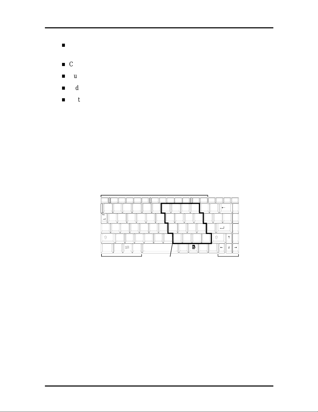
Keyboard
The built-in, 83-key keyboard (U.S.) or 79-key keyboard (UK and Germany) uses t he standard QWERTY format. The keyboard pro vides 12 function keys and 7 cursor contr ol keys,
with an Fn key for ROM-based key functions. The numeric keypad is embedded in the standard key layout.
Technical Information 1-5
Function Keys
Esc
F1 F2 F3 F4 F5 F6 F7 F8 F9 F10 F11 F12
Setup
!1@2#3$4%5^6&7*8(9)
Q
Tab
Cap
Lock
WERTYUI OP{[}]|
A
SDFGHJKL:;"
Z
Shift
Fn
Control Keys Embedded Numeric Keypad Cursor Control Keys
XCVBNM
Ctrl
Alt Alt
78 9 -
45 6 +
12 3 *
0
0
<,>.?
. /
Pause
PrtSc
Ins
SysReq
Shift
BkSp
Scroll Lock
\
Enter
Del
Home
PgUp
PgDn
End
Break
_
+
-
=
'
/
~
Ctrl
`
Figure Section 1 -3 Keyboa rd Layout
NEC VersaGlide
The NEC VersaGlide is a built-in mechanism that functions as the system’s mouse. It contro ls the on-screen po inter (cur sor). T o use the VersaGlide, move your finger across t he
NEC VersaGlide pad, and the cursor follo ws. The butto ns below the NEC VersaGlide allow the user to select or deselect menu items. Tap and double-tap are supported o n t he
VersaGlide pad.
The PS/2 Microsoft mouse is the system’s default pointing device, driver for the NEC Ver saGlide. If an external mo use is installed, then the VersaGlide is deactivated. A serial
mouse is not support ed.
SOLD BY laptopia2005 DO NOT RESELL!!
SOLD BY laptopia2005 DO NOT RESELL!!
1-6 Technical Information
VersaGlide
Left
Selection Button
Right
Selection Button
Figure Section 1-4 VersaGlide Location
CD-ROM Reader and Diskette Drive
A 10X CD-ROM reader and 1.44-MB diskette drive come installed in the NEC Versa
2600 Series on the front of the computer.
HARDWARE OVERVIEW—RIGHT SIDE
Review the following section for a description of the hardware on the right side of the NEC
Versa.
PC Card
Slots
Kensington Lock
Port
Figure Section 1 -5 Right Side Features
SOLD BY laptopia2005 DO NOT RESELL!!
SOLD BY laptopia2005 DO NOT RESELL!!
PC Card Slots
The PC card slot compart ment houses t wo Type II devices, or one Type II and one Type III
devices. For Type III cards, insert the PC card into the upper slot. Insert the card with the
pin sockets facing towards t he drive and the label facing up. To r emove the PC card, push
on the Eject butt on to r elease the pin connections and slowly pull out t he card.
The NEC Versa also comes with DOS/Windows PC card drivers for supporting various PC
cards like modem and network cards in Windows for Workgro ups configurations.
Kensington Lock
The Kensington Lock Port gives the user the option to add an o ptional Kensington Lock.
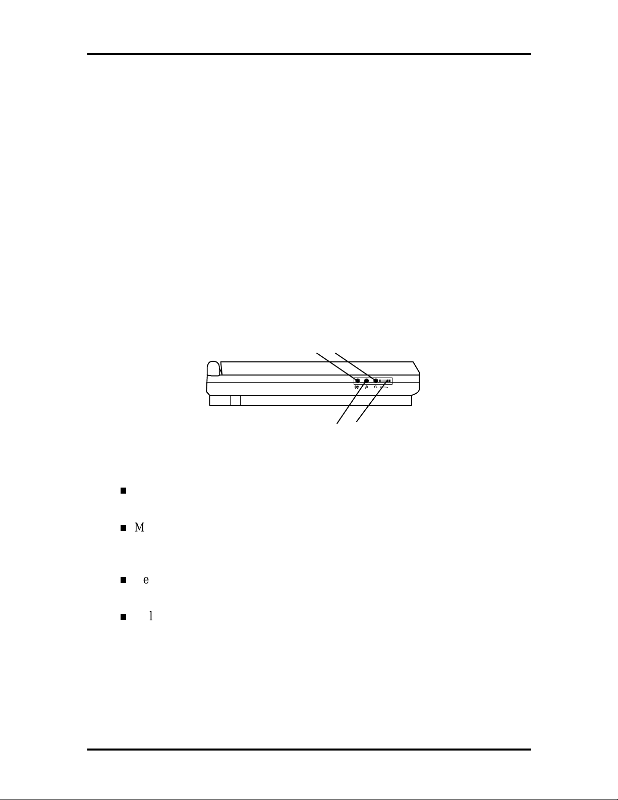
HARDWARE OVERVIEW—LEFT SIDE
Review the following section for a description of the hardware on the left side of the NEC
Versa.
Technical Information 1-7
Line In
Microphone Volume
Figure Section 1 -6 Left Side Features
Line-In — Use a cable to connect to the Line-Out port on the ot her audio system
Headphones
Control Dial
to r ecord or play.
Microphone (MIC) — Connects an external microphone for monophonic recording or amplification through the unit. Plugging in an external microphone disables
t he built-in microphone .
Headphones — Connects external headphones or speakers to the NEC Versa.
Plugging in headphones disables the built-in syst em speakers.
Volume Co nt rol — Contro ls the sp eake r or headphone volume.
SOLD BY laptopia2005 DO NOT RESELL!!
SOLD BY laptopia2005 DO NOT RESELL!!
1-8 Technical Information
HARDWARE OVERVIEW—REAR
Review the following section for a description of the hardware on the rear of the NEC
Versa.
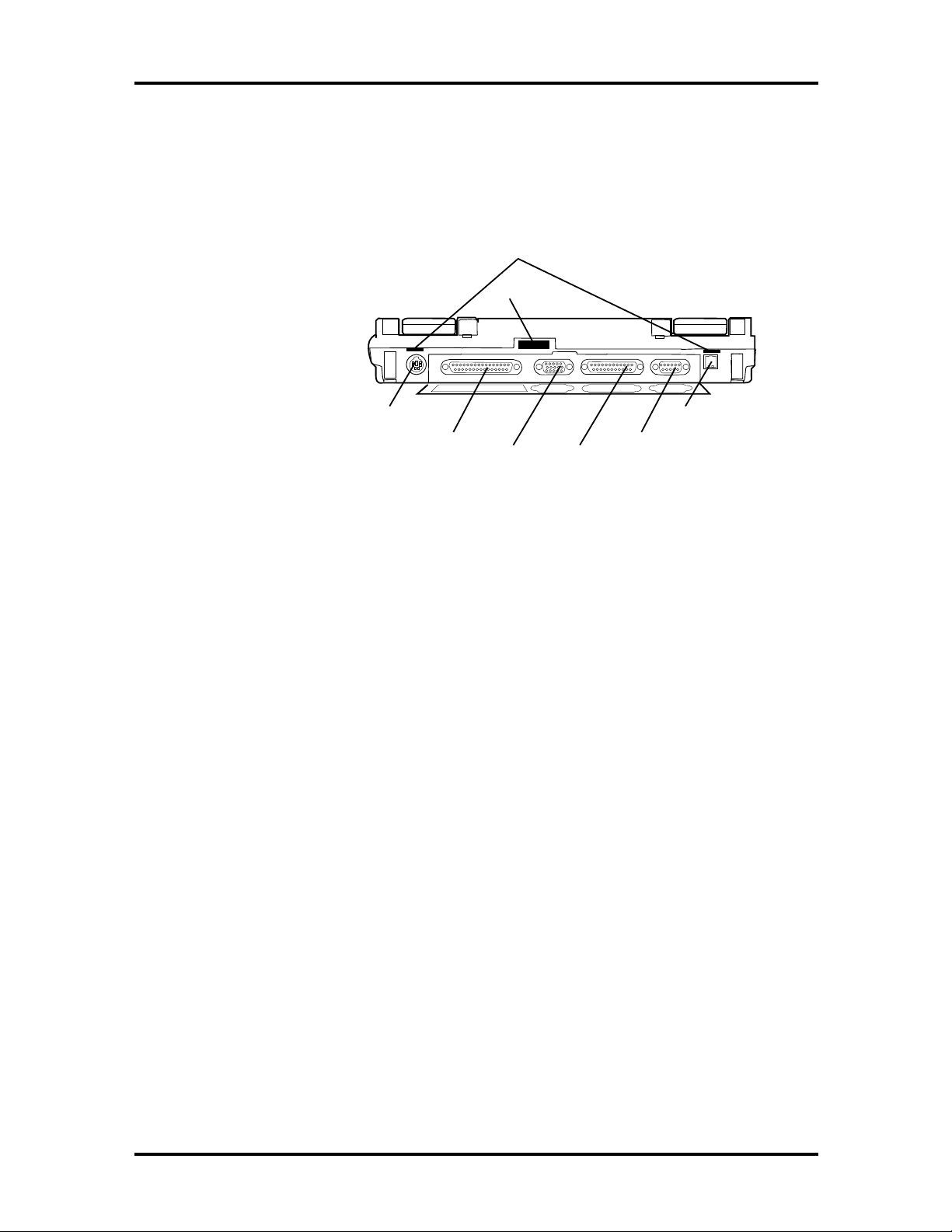
Port
Replicator Latch
IR Port
Serial
Port
AC Power
Port
Keyboard
Mouse Port
Expansion
Port
Monitor
Port
Parallel
Port
Figure Section 1-7 Rear Features
Infrared Port
This port lets you transfer files between your NEC Versa and an IR-equipped desktop or
notebook computer. You can also print to an IR-equipped printer without using cables.
Keyboard/Mouse Port
Use the standard PS/ 2 port to connect an external PS/2-st yle mouse or a PS/2-st yle keyboard to the system. A serial mouse is not suppo r ted through this connector nor is a Yadapter.
Expansion Port
This port provides a connection for NEC Versa options including the NEC Versa Port Replicator 2600.
Monitor (Video) Port
Use this 15-pin port to attach an external monitor to your NEC Versa. You can run the
LCD display and the external monitor simultaneously o r run either alone.
Parallel Port (LPT1)
The 25-pin print er port provides a parallel interface to which you can connect a parallel
printer or pocket net work adapter. Use this port to connect a parallel printer or ot her parallel device. The port is IEEE 1284 compatible. It supports bi-directional (AT) mode, Enhanced Capabilities Port (ECP) mo de , Enhanced Parallel Port ( EPP) mod e, (365SLcomp atible), and bi-dir ec tional (PS/ 2) mo de .
SOLD BY laptopia2005 DO NOT RESELL!!

SOLD BY laptopia2005 DO NOT RESELL!!
The parallel port’s default is PS/2 mode. Use Setup t o change the default to o ne of the following.
Standard
EPP
ECP
Serial Port (COM1)
The 9-pin serial port provides a serial interface to which you can connect an RS-232C device such as an external serial pr inter or modem. A serial mouse is not supported.
AC/DC Power Port
Use the power jack to attach the NEC Versa to an appropr iate DC po wer source, such as
the NEC Versa 2600 AC adapter or the optional NEC Versa 2600 DC car adapter.
Technical Information 1-9
HARDWARE OVERVIEW—INTERNAL COMPONENTS
Review the following sections for a description of the system’s internal hardware.
Battery Pack
The system uses a rechargeable lithium-ion (Li-Ion) batter y or r echargeable nickel metalhydrid e ( NiMH) as its transient power source. The batt er y pack installs in the compartment
next to the CD ROM reader on the front of the NEC Versa. The Li-Ion battery sto res 14.4
volts with a 2700 mAh capacity and the NiMH stores 9.6 volts with a 3500 mAh capacity.
The battery pack powers the NEC Versa for appro ximately 1:40 to 4 hours depending on
battery type and power management choice.
When battery power is getting low, connect the AC adapter t o a wall outlet and recharge
the battery. It takes 3 to 4 hours to recharge the battery.
SOLD BY laptopia2005 DO NOT RESELL!!
SOLD BY laptopia2005 DO NOT RESELL!!
1-10 Technical Information
Hard Disk Drive
A removable 2.5-inch, 1.44-GB hard disk drive ships wit h t he system. The 1.44-GB hard
disk drive specifications are listed next.
The 1.44-GB hard disk drive specifications are listed next.
Track-to-track seek r ate — 4 ms
Average seek time — 13 ms (read), 14 ms (write)
Revolutions per minute — 4009
Data transfer rate — 16.6 MB/sec
Media data rates — 39.6 − 61.8 Μbit/sec
Diskette Drive
The 3.5-inch 1.44-MB diskette drive is located in the front right of the system.
10X CD-ROM Reader
A 10X CD-ROM reader ships with all NEC Versa 2600 Series models. This ten-speed CDROM reader features t he latest in CD-ROM technology. It is located in the front center of
the system. The CD-ROM reader operates at different speeds depending on whether the CD
in use contains data or music. This improves video and sound quality.
SOLD BY laptopia2005 DO NOT RESELL!!
SOLD BY laptopia2005 DO NOT RESELL!!
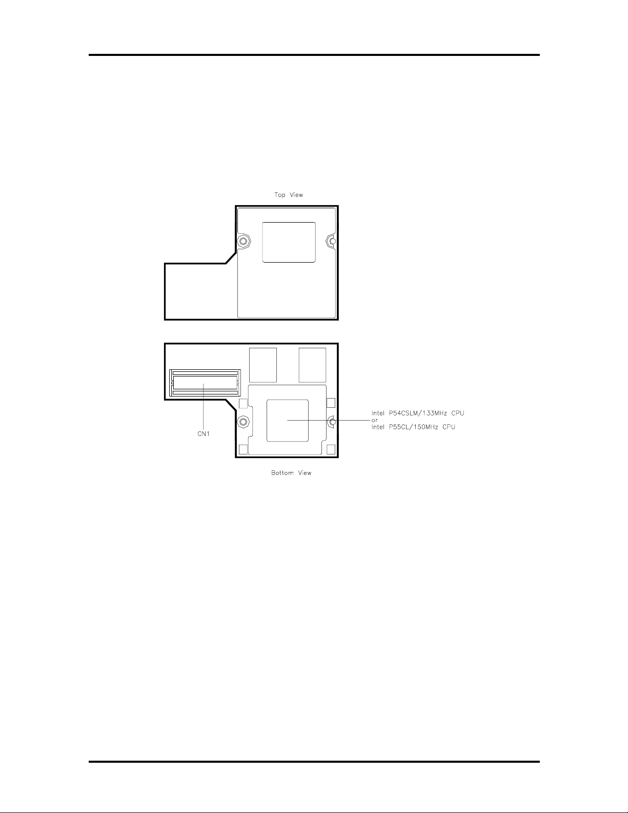
CPU Board
The CPU board is an L-shaped board situated under the keyboard.
The NEC Versa 2630CD and 2635CD models ship with Intel’s P54CSLM/133 MHz with
66 MHz bus speed. Modes 2650CD, 2655CD 2650CDT and 2655CDT ship with
P55CLM/150 MHz MMX wit h 60 MHz bus speed.
Technical Information 1-11
Figure Section 1-8 CPU Board Layout
SOLD BY laptopia2005 DO NOT RESELL!!
SOLD BY laptopia2005 DO NOT RESELL!!
1-12 Technical Information
Sound Board
Th e sound board provides the NEC Versa system with its au dio capabilities via line-in an d
headphone/microphone jacks. It is situated o n t op of the I/O board. The sound board integrates t he following features.
Figure Section 1 -9 Sound Board Layout
SOLD BY laptopia2005 DO NOT RESELL!!
SOLD BY laptopia2005 DO NOT RESELL!!
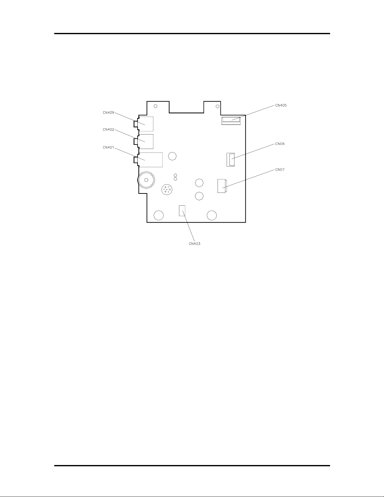
I/O Board
The system I/O board contains peripheral subsystems including serial, parallel and video
port s, P C card controller and charger.
Technical Information 1-13
Figure Section 1-10 I/O Board layout
Bridge Battery
The NiMH batter y (3.6 Vo lts, 60 mAh capacity) is attached to CN23 o n t he underside of
the Main board. It pr ovides battery backup and prevents data loss in the syst em’s complementar y metal ox ide semicond uc tor ( CMOS ) R AM. T his memo ry a rea co ntains information
on the system’s configuration like date, time, drives, and memory. The bridge batter y also
provid es power for main battery swapping, while in suspe n d mode. The bridge ba ttery lasts
approximately two year s.
SOLD BY laptopia2005 DO NOT RESELL!!
SOLD BY laptopia2005 DO NOT RESELL!!
1-14 Technical Information
SYSTEM MEMORY
The system board provides 16-MB of standard random access memory (RAM).
Optional memory DIMMS with a value of 8-, 16-, or 32-MB can be added to increase sys-
tem memory up to a maximum of 80-MB (70ns Fast Page access o r HyperPage access).
The DIMMS must be added in pairs of the same capacit y. In addition, 256-KB of read-only
memory (ROM), 1 x 28F020, enables the system BIOS to be flashed.
The system provides 1-MB (TFT models) or 1.5-MB (DSTN model) of video RAM (60ns
HyperPage mode, self r efresh).
The following Cache RAM is provided:
L1:
16KB (Internal Pentium P54C-133)
32KB (Internal Pentium P55C-150MMX)
L2: 256 KB PipeLineBurst-SRAM.
Memory Map
The system supports system and video shadowing, both controlled through complementary
metal oxid e semiconductor (CMOS). T he system supports BIOS as a cacheable area with
write pr otection. Table Section 1 -2 lists th e system memo ry map.
Table Section 1-2 Memory Map
Memory Space Size Function
0000000h-0009FFFFh 640 KB DOS Appl ications & O ptional Memory Space Gap
00A0000h-000B7FFF 96 KB Video (VG A ) Graphic Memory
00B8000h-000BFFFFh 32 KB Text Mode Memory (SMM Space)
00C0000h-000C9FFF 40 KB Video (VGA) BIOS
00CA000h-000CFFFFh 24 KB PnP BIOS / PCI BIOS
00D0000h-000DFFFFh 64 KB Setup / PCMCIA Window (Extended Memory or
Upper Memory B lock)
00E0000h-000FFFFFh 128 KB System BIOS ROM
0000000h -00FFFFFFh 16 MB Total Base Memory
0000000h -FFFEFFFFh 80 MB Total Extensi on M emory
SOLD BY laptopia2005 DO NOT RESELL!!
SOLD BY laptopia2005 DO NOT RESELL!!
SYSTEM VIDEO
The system's LCD operates using the Chips and Technologies 65550B VGA Controller.
Video signals travel fr om the contro ller through the system's 15-pin D-SUB connector using 5 volts.
System video integrates a PCI- bus interface. The system ship s with 1 MB on TFT units and
1.5MB on DSTN of Video RAM (VRAM). It supports video modes up to 800 x 600 with
64K c olors in LCD mode.
See A ppendix B for a list o f Video modes.
PARALLEL INTERFACE
The system's parallel interface integrates National Semiconductor’s PC87336VJG Peripheral I/O chip with a 25-pin D-subconnector. The po r t is located o n t he system's rear panel.
The modes of operation available for a PC87336VJG chip are:
Technical Information 1-15
comp atibility mod e
nibble mode
byte mo de
Ex tended Capabilities Port (ECP)
Enhanced Parallel Port (EPP).
The user selects between three parallel interface modes using Auto Setup. These include
un idir ec tional, bi-directiona l or e nha n ce d. Un idir ec tional mode sends data output from the
standard ISA port only. Bi-directional mode sends data using the standard ISA port o r PS/2
technology. Enhanced mode enables high speed data transmission to occur using either the
un idir ec tional or bi-direct ion al modes.
The default parallel port address is 378h and the interrupt level is IRQ07. Pin locations for
the parallel interface are listed in Appendix A.
SOLD BY laptopia2005 DO NOT RESELL!!

SOLD BY laptopia2005 DO NOT RESELL!!
1-16 Technical Information
SERIAL INTERFACE
The RS-232C serial port is a 9-pin connector on the system’s rear panel. The serial port
consists of a 16550A compatible serial port cont r oller with a programmable baud rate up to
115,200 bps. The serial port co nnects an RS-232C device or an external modem. The default serial port address is 3F8h and the interrupt level is IRQ04.
NEC VERSA CHIP SET
Refer to Table Section 1-3 for a quick summar y of the chip types used in the system. See
the Abbreviations section at the beginning of this manual for a translation of chip technologies acronyms.
Table Sec tion 1-3 NEC Versa 2600 Series Chip Types and Technologies
Chip Manufacturer Description Technology
Intel Pentium P54CSLM
Intel Pentium P 55CL
N28F020-150 Intel 256k x 8 Flash ROM
82C557M Opti Viper N+ System Controller 208-pin TQFP
82C556M Opti Viper N+ Data Path Controller 176-pin TQFP
82C558E Opti Viper N+ PCI I DE ISA Xcelerator 208-pin TQFP
PC87336VJG National
H8/3434 Hitachi Keyboard Controller 100-pin TQFP
C&T 65550B Chips &
OZ6730D O2 Micro PC Card Controller 208-pin PQF P
ESS1688 ESS Sound Controller 100-pin PQFP
Intel
Intel
Semiconductor
Technologi es
133 MHz CPU
150MMX
Diskette Controller, IDE,
Parallel Interface
VGA Controller 208-pin FQFP
320-pin TCP
320-pin TCP
32-pin TSO P
100-pin QFP
Intel Pentium P55CLM Microprocessor
The 133 MHz Intel Pentium microprocessor used in the NEC Versa series computer is built
o n In tel’s advanced 3.3V BiCMOS silicon technology. The CP U has power management
features. NEC adop ted the chip specifically for its pipelined Floating Point Unit (FPU), and
lo cal int errup t mana ge ment.
256K X Flash ROM
The N28F020 flash ROM is a 40-pin, (TSOP). The chip allows easy updates to the system's
BIOS if needed. More specifically, the ROM is flashe d e lectronically, installing the latest
BIOS revisions to the system. It is possible to reprogram the BIOS up to 100, 000 times.
See Section 2, Setup and Operation, for BIOS update pro cedures.
SOLD BY laptopia2005 DO NOT RESELL!!

SOLD BY laptopia2005 DO NOT RESELL!!
The N28F020 provides the syst em upgrade capability as well as t he follow ing:
256 KB memory
Quick- Pulse Progra mmin g Algorithm
150 nanoseconds (ns) maximum access time
ET OX Nonvolatile flash te chnolo gy
CMOS low power consumption
ROM BIOS
The system uses a Flash ROM known as t he system's ROM BIOS to store machine language programs. The BIOS size is 256 KB, consisting of the system utility (for PC cards,
Auto Setup), system BIOS, video BIOS, and power management.
The BIOS programs execute the power-on self-test (POS T), initialize CP U controllers, and
interact with the LCD indicator panel, diskette drive, hard drive, communication devices
and peripherals. The system BIOS also contains Auto Set up and provides VGA controller
support. T he ROM BIOS is copied into RAM (shadowing) for optimum performance.
Technical Information 1-17
The ROM BIOS cont ains both the system and video BIOS. T he system BIOS is located in
the upper portion of the device, video BIOS is located in the lower portion. System BIOS is
located between F000h-FFFFh.
The BIOS often changes after the product release to pro vide enhanced features or bug
fixes. To acquire the latest BIOS r elease, t he ROM is flashed electro nically allowing the
BIOS update to occur without removing the ROM. See Section 2, Setup and Operation, for
BIOS upgrade procedures.
VGA Controller
The Chips and Technologies 65550B is a PCI 64-bit Graphics Accelerator. The integrated
programmable linear addr ess feature accelerat es the graphics user interface (GUI) performance. The controller also supports Hardware Multimedia and VES A interface standards.
The contro ller provides advanced power management that helps to minimize power usage
in:
normal operation
Standby (sleep) mode
panel off pow er sa ving modes.
SOLD BY laptopia2005 DO NOT RESELL!!

SOLD BY laptopia2005 DO NOT RESELL!!
1-18 Technical Information
Keyboard Controller
The keyboard controller (H8/3434) supports a PS/2-style keyboard, mouse and password
security feature. Refer to Appendix A for keyboard interface connector pin assignments.
When data is written to the output buffer, the controller generates an interrupt, and requests
the CPU to receive the data. The contr oller auto matically adds an even parity bit to the data
sent and waits for a response. The device must acknowledge that t he dat a was successfully
received by sending a response to the contr oller for each byte of data received.
PC Card Controller
The O2 Micro OZ6730D controller with the PCI bus, PC CardBus socket and configuration
registers t o pro vide:
compliant with PCI 2.1 and 1995 PC card standards
PC Card slot s with hot insertion and removal
independent Read and Write buffers for each direction
Sound Integrated Circuit
The ESS1688 chip is a single combo chip. This dynamic audio circuitry provides the following:
ISA 16-bit bus interface chip
audio digit al processor
Plug and Play suppo r t
high performance 16-bit Sigma Delta Stereo Codec
Sound Blaster™ 16 register compatible mixer with AGC
bu ilt-in ana log joystick quad timer .
SOLD BY laptopia2005 DO NOT RESELL!!

SOLD BY laptopia2005 DO NOT RESELL!!
Interrupt Controllers
Using interrupts, it is possible to change the system’s code sequence. To change the sequence, reassign the interrupt- levels. Fifteen interrupt s can be used with a cascade connection of two 82C59 interrupt controllers.
Interrupt- level assignments 0 through 15 are listed in Table Section 1-4, in order o f
decreasing priority. These assignments can be adjusted by PnP function.
Table Sec tion 1-4 Interrupt Controllers
Technical Information 1-19
Controller
Master/Slave Priority
Master 1 IRQ00 System Timer
Master 2 IRQ01 Keyboard
Master 3–10 IRQ02 Second Interr upt Controller
Slave 4 IRQ03 PCMCIA Modem Card (default)
Slave 5 IRQ04 COM1 (Int er nal serial port )
Slave 6 IRQ05 Sound Chip, MIDI (default)
Slave 7 IRQ06 Floppy Disk Drive Controller
Slave 8 IRQ07 LPT1 Def ault (int er nal printer por t)
Slave 9 IRQ08 Real Ti me Clock
Slave 10 IRQ09 MIDI
Master 11 IRQ10 Not used
Master 12 IRQ11 Not used
Master 13 IRQ12 Internal Glide Pointer or External PS/2 Mouse
Master 14 IRQ13 Co-Processor
Name
Device
Master 15 IRQ14 Hard Dr ive
Master IRQ15 CD-ROM
SOLD BY laptopia2005 DO NOT RESELL!!
SOLD BY laptopia2005 DO NOT RESELL!!
1-20 Technical Information
Table 1-5 DMA Channel
DMA Chann el Assigned Device
DMA0 Enhanced Printer Port
DMA1 Sound Chip ( default )
DMA2 FDD Contr oller
DMA3 Not Used
DMA4 Cascade fr om DMA Controller, P
DMA5 Not Used
DMA6 Not Used
DMA7 Not Used
POWER MANAGEMENT OVERVIEW
Power Management in the NEC Versa lets you conserve energy, save battery power, extend
the life of your LCD backlight , and protect against data loss due t o low battery power.
Set so me features to function automatically or activate them manually with the keyboard or
a butto n. It is wise to keep Power Management features enabled, even when using AC
power.
The system arrives set up with many power-saving features already enabled. See the following table.
Table Section 1-6 Automatic Power-Saving Features
Device
Video 2 minutes Video t ur ns off after there is no keyboard or
Hard Disk 15 seconds Hard disk mot or stops when hard disk i s not ac c essed
Standby 2 minut es System enters Standby m ode after total system
Default
Timeout
Comment
VersaGlide input f or the specified tim eout.
for specified t imeout.
inactivity.
You can change the timeout period for any of the devices using Setup. See Section 2 for
Setup u tility pr ocedu res.
SOLD BY laptopia2005 DO NOT RESELL!!

SOLD BY laptopia2005 DO NOT RESELL!!
System Power Management
The system power management consists of the following operation modes. These modes
are:
Active Mode In active mode, the system uses maximum power. I t operates
with the default clock speed. The system continues to run at this speed unless
overwritten by the power management features.
Standby Mode The system switches auto matically to Standby mode. This
eliminates unnecessary power co nsumption when you operate the system on battery power or AC. Standby mode shuts down the LCD panel, providing privacy as
well as power savings.
Suspend Mode Suspend mode causes the CPU power down, local devices to
shut down, and register values to be stored in RAM.
The system resumes Active mode when you press the Po we r butto n or the system
is s et to resume at a certain t ime of d ay. Suspen d mode le ts yo u save power w ith out first saving the working data.
Technical Information 1-21
Press the Power button t o enter Suspend mode when you need to be away from
the system for a short period of time and want to retur n t o where you left off.
Local Power Management
Use Auto Setup to select one of four power management sett ings for local devices. T hese
includ e Maximum Ba ttery Life, G ood Bat ter y Life, G ood Per formance, and Maximu m
Performance. The power management levels are also available during AC operation. The
NEC Versa computer ships with Longest Batt er y Life as the default power management
setting. See Section 2 for specific procedures on using Auto Setup to select the power management settings.
When set to Maximum Battery Life, C MOS w ill set local dev ice timeout valu es, a lo cal
stand-by timeout value, and a suspend timeout value to ensure the longest battery life. The
Ma ximum Performan ce setting s elects CMOS values that will p rovide min imal e nergy sav ings and a shorter bat tery life. The custom settings enable end-users to set the timeout values of their choice.
PLUG AND PLAY
Th e N EC Ve rs a features Plug and Play functio nality. P lug and Play is th e a b ility of th e
BIOS and/or operating system to dynamically assign system resources to a newly installed
device without user intervention.
For example, you can suspend the system, add an external keybo ar d , mouse, or monitor,
and when yo u r esume working, the NEC Versa recognizes the devices t hat have been connected to it. Simila rly, you can remove external dev ices in Suspend mode and the N EC
Versa detect s the status when resumed.
SOLD BY laptopia2005 DO NOT RESELL!!
 Loading...