


Command Manual
NWA-008844-001
ISSUE 5.0

LIABILITY DISCLAIMER
NEC Infrontia Corporation reserves the right to change the specifications, functions, or features, at any time, without notice.
NEC Infrontia Corporation has prepared this document for use by its
employees and customers. The information contained herein is the
property of NEC Infrontia Corporation and shall not be reproduced
without prior written approval from NEC Infrontia Corporation.
NEAX and D
term
are registered trademarks of NEC Corporation.
MATWorX is a trademark of NEC Corporation.
Copyright 2007
NEC Infrontia Corporation

PAG E N o.
i 1 2 3 4 5
ii 1 2 3 4 5
iii 1 2 3 4 5
iv 1234
v 1 2 3 4 5
vi 1 2 3 4 5
vii 3 4 5
viii 3 4
1 1 2 3 4 5
2 1 2 3 4 5
312345
41234
5 1 2 3 4 5
6 1 2 3 4 5
712345
81234
9 1 2 3 4 5
10 1 2 3 4 5
11 12345
12 1234
13 1 2 3 4 5
14 1 2 3 4 5
15 12345
16 1234
17 1 2 3 4 5
18 1 2 3 4 5
19 12345
20 1234
21 1 2 3 4 5
22 1 2 3 4 5
23 12345
24 1234
25 1 2 3 4 5
26 1 2 3 4 5
27 12345
28 1234
29 1 2 3 4 5
30 1 2 3 4 5
DATE JUNE, 2005 DATE DECEMBER, 2005 DATE JULY, 2006 DATE NOVEMBER, 2006
DATE JUNE, 2007 DATE DATE DATE
1234
ISSUE 1 ISSUE 2 ISSUE 3 ISSUE 4
ISSUE 5 ISSUE 6 ISSUE 7 ISSUE 8
ISSUE No.
5678
5
5
5
5
5
5
5
5
5
PAG E N o.
31 12345
32 1234
33 1 2 3 4 5
34 1 2 3 4 5
35 12345
36 1234
37 1 2 3 4 5
38 1 2 3 4 5
39 12345
40 1234
41 1 2 3 4 5
42 1 2 3 4 5
43 12345
44 1234
45 1 2 3 4 5
46 1 2 3 4 5
47 12345
48 1234
49 1 2 3 4 5
50 1 2 3 4 5
51 12345
52 1234
53 1 2 3 4 5
54 1 2 3 4 5
55 12345
56 1234
57 1 2 3 4 5
58 1 2 3 4 5
59 12345
60 1234
61 1 2 3 4 5
62 1 2 3 4 5
63 12345
64 1234
65 1 2 3 4 5
66 1 2 3 4 5
67 12345
68 1234
1234
ISSUE No.
5678
5
5
5
5
5
5
5
5
5
5
NEAX 2000 IPS
Command Manual
Revision Sheet 1/14
NWA-008844-001

PAG E N o.
69 1 2 3 4 5
70 1 2 3 4 5
71 12345
72 1234
73 1 2 3 4 5
74 1 2 3 4 5
75 12345
76 1234
77 1 2 3 4 5
78 1 2 3 4 5
79 12345
80 1234
81 1 2 3 4 5
82 1 2 3 4 5
83 12345
84 1234
85 1 2 3 4 5
86 1 2 3 4 5
87 12345
88 1234
89 1 2 3 4 5
90 1 2 3 4 5
91 12345
92 1234
93 1 2 3 4 5
94 1 2 3 4 5
95 12345
96 1234
97 1 2 3 4 5
98 1 2 3 4 5
99 12345
100 1234
101 1 2 3 4 5
102 1 2 3 4 5
103 12345
104 1234
105 1 2 3 4 5
106 1 2 3 4 5
DATE JUNE, 2005 DATE DECEMBER, 2005 DATE JULY, 2006 DATE NOVEMBER, 2006
DATE JUNE, 2007 DATE DATE DATE
1234
ISSUE 1 ISSUE 2 ISSUE 3 ISSUE 4
ISSUE 5 ISSUE 6 ISSUE 7 ISSUE 8
ISSUE No.
5678
5
5
5
5
5
5
5
5
5
PAG E N o.
107 1 2 3 4 5
108 1 2 3 4
109 1 2 3 4 5
110 1 2 3 4 5
111 12345
112 1234
113 1 2 3 4 5
114 1 2 3 4 5
115 12345
116 1234
117 1 2 3 4 5
118 1 2 3 4 5
119 12345
120 1 2 3 4
121 1 2 3 4 5
122 1 2 3 4 5
123 1 2 3 4 5
124 1 2 3 4
125 1 2 3 4 5
126 1 2 3 4 5
127 1 2 3 4 5
128 1 2 3 4
129 1 2 3 4 5
130 1 2 3 4 5
131 1 2 3 4 5
132 1 2 3 4
133 1 2 3 4 5
134 1 2 3 4 5
135 1 2 3 4 5
136 1 2 3 4
137 1 2 3 4 5
138 1 2 3 4 5
139 1 2 3 4 5
140 1 2 3 4
141 1 2 3 4 5
142 1 2 3 4 5
143 1 2 3 4 5
144 1 2 3 4
1234
ISSUE No.
5678
5
5
5
5
5
5
5
5
5
5
NEAX 2000 IPS
Command Manual
Revision Sheet 2/14
NWA-008844-001

PAG E N o.
145 1 2 3 4 5
146 1 2 3 4 5
147 12345
148 1234
149 1 2 3 4 5
150 1 2 3 4 5
151 12345
152 1234
153 1 2 3 4 5
154 1 2 3 4 5
155 12345
156 1234
157 1 2 3 4 5
158 1 2 3 4 5
159 12345
160 1234
161 1 2 3 4 5
162 1 2 3 4 5
163 12345
164 1234
165 1 2 3 4 5
166 1 2 3 4 5
167 12345
168 1234
169 1 2 3 4 5
170 1 2 3 4 5
171 12345
172 1234
173 1 2 3 4 5
174 1 2 3 4 5
175 12345
176 1234
177 1 2 3 4 5
178 1 2 3 4 5
179 12345
180 1234
181 1 2 3 4 5
182 1 2 3 4 5
DATE JUNE, 2005 DATE DECEMBER, 2005 DATE JULY, 2006 DATE NOVEMBER, 2006
DATE JUNE, 2007 DATE DATE DATE
1234
ISSUE 1 ISSUE 2 ISSUE 3 ISSUE 4
ISSUE 5 ISSUE 6 ISSUE 7 ISSUE 8
ISSUE No.
5678
5
5
5
5
5
5
5
5
5
PAG E N o.
183 1 2 3 4 5
184 1 2 3 4
185 1 2 3 4 5
186 1 2 3 4 5
187 1 2 3 4 5
188 1 2 3 4
189 1 2 3 4 5
190 1 2 3 4 5
191 1 2 3 4 5
192 1 2 3 4
193 1 2 3 4 5
194 1 2 3 4 5
195 1 2 3 4 5
196 1 2 3 4
197 1 2 3 4 5
198 1 2 3 4 5
199 1 2 3 4 5
200 1 2 3 4
201 1 2 3 4 5
202 1 2 3 4 5
203 1 2 3 4 5
204 1 2 3 4
205 1 2 3 4 5
206 1 2 3 4 5
207 1 2 3 4 5
208 1 2 3 4
209 1 2 3 4 5
210 1 2 3 4 5
211 12345
212 1 2 3 4
213 1 2 3 4 5
214 1 2 3 4 5
215 1 2 3 4 5
216 1 2 3 4
217 1 2 3 4 5
218 1 2 3 4 5
219 1 2 3 4 5
220 1 2 3 4
1234
ISSUE No.
5678
5
5
5
5
5
5
5
5
5
5
NEAX 2000 IPS
Command Manual
Revision Sheet 3/14
NWA-008844-001

PAG E N o.
221 1 2 3 4 5
222 1 2 3 4 5
223 12345
224 1234
225 1 2 3 4 5
226 1 2 3 4 5
227 12345
228 1234
229 1 2 3 4 5
230 1 2 3 4 5
231 12345
232 1234
233 1 2 3 4 5
234 1 2 3 4 5
235 12345
236 1234
237 1 2 3 4 5
238 1 2 3 4 5
239 12345
240 1234
241 1 2 3 4 5
242 1 2 3 4 5
243 12345
244 1234
245 1 2 3 4 5
246 1 2 3 4 5
247 12345
248 1234
249 1 2 3 4 5
250 1 2 3 4 5
251 12345
252 1234
253 1 2 3 4 5
254 1 2 3 4 5
255 12345
256 1234
257 1 2 3 4 5
258 1 2 3 4 5
DATE JUNE, 2005 DATE DECEMBER, 2005 DATE JULY, 2006 DATE NOVEMBER, 2006
DATE JUNE, 2007 DATE DATE DATE
1234
ISSUE 1 ISSUE 2 ISSUE 3 ISSUE 4
ISSUE 5 ISSUE 6 ISSUE 7 ISSUE 8
ISSUE No.
5678
5
5
5
5
5
5
5
5
5
PAG E N o.
259 1 2 3 4 5
260 1 2 3 4
261 1 2 3 4 5
262 1 2 3 4 5
263 1 2 3 4 5
264 1 2 3 4
265 1 2 3 4 5
266 1 2 3 4 5
267 1 2 3 4 5
268 1 2 3 4
269 1 2 3 4 5
270 1 2 3 4 5
271 1 2 3 4 5
272 1 2 3 4
273 1 2 3 4 5
274 1 2 3 4 5
275 1 2 3 4 5
276 1 2 3 4
277 1 2 3 4 5
278 1 2 3 4 5
279 1 2 3 4 5
280 1 2 3 4
281 1 2 3 4 5
282 1 2 3 4 5
283 1 2 3 4 5
284 1 2 3 4
285 1 2 3 4 5
286 1 2 3 4 5
287 1 2 3 4 5
288 1 2 3 4
289 1 2 3 4 5
290 1 2 3 4 5
291 1 2 3 4 5
292 1 2 3 4
293 1 2 3 4 5
294 1 2 3 4 5
295 1 2 3 4 5
296 1 2 3 4
1234
ISSUE No.
5678
5
5
5
5
5
5
5
5
5
5
NEAX 2000 IPS
Command Manual
Revision Sheet 4/14
NWA-008844-001

PAG E N o.
297 1 2 3 4 5
298 1 2 3 4 5
299 12345
300 1234
301 1 2 3 4 5
302 1 2 3 4 5
303 12345
304 1234
305 1 2 3 4 5
306 1 2 3 4 5
307 12345
308 1234
309 1 2 3 4 5
310 1 2 3 4 5
311 1 2 3 4 5
312 1234
313 1 2 3 4 5
314 1 2 3 4 5
315 12345
316 1234
317 1 2 3 4 5
318 1 2 3 4 5
319 12345
320 1234
321 1 2 3 4 5
322 1 2 3 4 5
323 12345
324 1234
325 1 2 3 4 5
326 1 2 3 4 5
327 12345
328 1234
329 1 2 3 4 5
330 1 2 3 4 5
331 12345
332 1234
333 1 2 3 4 5
334 1 2 3 4 5
DATE JUNE, 2005 DATE DECEMBER, 2005 DATE JULY, 2006 DATE NOVEMBER, 2006
DATE JUNE, 2007 DATE DATE DATE
1234
ISSUE 1 ISSUE 2 ISSUE 3 ISSUE 4
ISSUE 5 ISSUE 6 ISSUE 7 ISSUE 8
ISSUE No.
5678
5
5
5
5
5
5
5
5
5
PAG E N o.
335 1 2 3 4 5
336 1 2 3 4
337 1 2 3 4 5
338 1 2 3 4 5
339 1 2 3 4 5
340 1 2 3 4
341 1 2 3 4 5
342 1 2 3 4 5
343 1 2 3 4 5
344 1 2 3 4
345 1 2 3 4 5
346 1 2 3 4 5
347 1 2 3 4 5
348 1 2 3 4
349 1 2 3 4 5
350 1 2 3 4 5
351 1 2 3 4 5
352 1 2 3 4
353 1 2 3 4 5
354 1 2 3 4 5
355 1 2 3 4 5
356 1 2 3 4
357 1 2 3 4 5
358 1 2 3 4 5
359 1 2 3 4 5
360 1 2 3 4
361 1 2 3 4 5
362 1 2 3 4 5
363 1 2 3 4 5
364 1 2 3 4
365 1 2 3 4 5
366 1 2 3 4 5
367 1 2 3 4 5
368 1 2 3 4
369 1 2 3 4 5
370 1 2 3 4 5
371 1 2 3 4 5
372 1 2 3 4
1234
ISSUE No.
5678
5
5
5
5
5
5
5
5
5
5
NEAX 2000 IPS
Command Manual
Revision Sheet 5/14
NWA-008844-001

PAG E N o.
373 1 2 3 4 5
374 1 2 3 4 5
375 12345
376 1234
377 1 2 3 4 5
378 1 2 3 4 5
379 12345
380 1234
381 1 2 3 4 5
382 1 2 3 4 5
383 12345
384 1234
385 1 2 3 4 5
386 1 2 3 4 5
387 12345
388 1234
389 1 2 3 4 5
390 1 2 3 4 5
391 12345
392 1234
393 1 2 3 4 5
394 1 2 3 4 5
395 12345
396 1234
397 1 2 3 4 5
398 1 2 3 4 5
399 12345
400 1234
401 1 2 3 4 5
402 1 2 3 4 5
403 12345
404 1234
405 1 2 3 4 5
406 1 2 3 4 5
407 12345
408 1234
409 1 2 3 4 5
410 1 2 3 4 5
DATE JUNE, 2005 DATE DECEMBER, 2005 DATE JULY, 2006 DATE NOVEMBER, 2006
DATE JUNE, 2007 DATE DATE DATE
1234
ISSUE 1 ISSUE 2 ISSUE 3 ISSUE 4
ISSUE 5 ISSUE 6 ISSUE 7 ISSUE 8
ISSUE No.
5678
5
5
5
5
5
5
5
5
5
PAG E N o.
411 12345
412 1 2 3 4
413 1 2 3 4 5
414 1 2 3 4 5
415 1 2 3 4 5
416 1 2 3 4
417 1 2 3 4 5
418 1 2 3 4 5
419 1 2 3 4 5
420 1 2 3 4
421 1 2 3 4 5
422 1 2 3 4 5
423 1 2 3 4 5
424 1 2 3 4
425 1 2 3 4 5
426 1 2 3 4 5
427 1 2 3 4 5
428 1 2 3 4
429 1 2 3 4 5
430 1 2 3 4 5
431 1 2 3 4 5
432 1 2 3 4
433 1 2 3 4 5
434 1 2 3 4 5
435 1 2 3 4 5
436 1 2 3 4
437 1 2 3 4 5
438 1 2 3 4 5
439 1 2 3 4 5
440 1 2 3 4
441 1 2 3 4 5
442 1 2 3 4 5
443 1 2 3 4 5
444 1 2 3 4
445 1 2 3 4 5
446 1 2 3 4 5
447 1 2 3 4 5
448 1 2 3 4
1234
ISSUE No.
5678
5
5
5
5
5
5
5
5
5
5
NEAX 2000 IPS
Command Manual
Revision Sheet 6/14
NWA-008844-001

PAG E N o.
449 1 2 3 4 5
450 1 2 3 4 5
451 12345
452 1234
453 1 2 3 4 5
454 1 2 3 4 5
455 12345
456 1234
457 1 2 3 4 5
458 1 2 3 4 5
459 12345
460 1234
461 1 2 3 4 5
462 1 2 3 4 5
463 12345
464 1234
465 1 2 3 4 5
466 1 2 3 4 5
467 12345
468 1234
469 1 2 3 4 5
470 1 2 3 4 5
471 12345
472 1234
473 1 2 3 4 5
474 1 2 3 4 5
475 12345
476 1234
477 1 2 3 4 5
478 1 2 3 4 5
479 12345
480 1234
481 1 2 3 4 5
482 1 2 3 4 5
483 12345
484 1234
485 1 2 3 4 5
486 1 2 3 4 5
DATE JUNE, 2005 DATE DECEMBER, 2005 DATE JULY, 2006 DATE NOVEMBER, 2006
DATE JUNE, 2007 DATE DATE DATE
1234
ISSUE 1 ISSUE 2 ISSUE 3 ISSUE 4
ISSUE 5 ISSUE 6 ISSUE 7 ISSUE 8
ISSUE No.
5678
5
5
5
5
5
5
5
5
5
PAG E N o.
487 1 2 3 4 5
488 1 2 3 4
489 1 2 3 4 5
490 1 2 3 4 5
491 1 2 3 4 5
492 1 2 3 4
493 1 2 3 4 5
494 1 2 3 4 5
495 1 2 3 4 5
496 1 2 3 4
497 1 2 3 4 5
498 1 2 3 4 5
499 1 2 3 4 5
500 1 2 3 4
501 1 2 3 4 5
502 1 2 3 4 5
503 1 2 3 4 5
504 1 2 3 4
505 1 2 3 4 5
506 1 2 3 4 5
507 1 2 3 4 5
508 1 2 3 4
509 1 2 3 4 5
510 1 2 3 4 5
511 12345
512 1 2 3 4
513 1 2 3 4 5
514 1 2 3 4 5
515 1 2 3 4 5
516 1 2 3 4
517 1 2 3 4 5
518 1 2 3 4 5
519 1 2 3 4 5
520 1 2 3 4
521 1 2 3 4 5
522 1 2 3 4 5
523 1 2 3 4 5
524 1 2 3 4
1234
ISSUE No.
5678
5
5
5
5
5
5
5
5
5
5
NEAX 2000 IPS
Command Manual
Revision Sheet 7/14
NWA-008844-001

PAG E N o.
525 1 2 3 4 5
526 1 2 3 4 5
527 12345
528 1234
529 1 2 3 4 5
530 1 2 3 4 5
531 12345
532 1234
533 1 2 3 4 5
534 1 2 3 4 5
535 12345
536 1234
537 1 2 3 4 5
538 1 2 3 4 5
539 12345
540 1234
541 1 2 3 4 5
542 1 2 3 4 5
543 12345
544 1234
545 1 2 3 4 5
546 1 2 3 4 5
547 12345
548 1234
549 1 2 3 4 5
550 1 2 3 4 5
551 12345
552 1234
553 1 2 3 4 5
554 1 2 3 4 5
555 12345
556 1234
557 1 2 3 4 5
558 1 2 3 4 5
559 12345
560 1234
561 1 2 3 4 5
562 1 2 3 4 5
DATE JUNE, 2005 DATE DECEMBER, 2005 DATE JULY, 2006 DATE NOVEMBER, 2006
DATE JUNE, 2007 DATE DATE DATE
1234
ISSUE 1 ISSUE 2 ISSUE 3 ISSUE 4
ISSUE 5 ISSUE 6 ISSUE 7 ISSUE 8
ISSUE No.
5678
5
5
5
5
5
5
5
5
5
PAG E N o.
563 1 2 3 4 5
564 1 2 3 4
565 1 2 3 4 5
566 1 2 3 4 5
567 1 2 3 4 5
568 1 2 3 4
569 1 2 3 4 5
570 1 2 3 4 5
571 1 2 3 4 5
572 1 2 3 4
573 1 2 3 4 5
574 1 2 3 4 5
575 1 2 3 4 5
576 1 2 3 4
577 1 2 3 4 5
578 1 2 3 4 5
579 1 2 3 4 5
580 1 2 3 4
581 1 2 3 4 5
582 1 2 3 4 5
583 1 2 3 4 5
584 1 2 3 4
585 1 2 3 4 5
586 1 2 3 4 5
587 1 2 3 4 5
588 1 2 3 4
589 1 2 3 4 5
590 1 2 3 4 5
591 1 2 3 4 5
592 1 2 3 4
593 1 2 3 4 5
594 1 2 3 4 5
595 1 2 3 4 5
596 1 2 3 4
597 1 2 3 4 5
598 1 2 3 4 5
599 1 2 3 4 5
600 1 2 3 4
1234
ISSUE No.
5678
5
5
5
5
5
5
5
5
5
5
NEAX 2000 IPS
Command Manual
Revision Sheet 8/14
NWA-008844-001

PAG E N o.
601 1 2 3 4 5
602 1 2 3 4 5
603 12345
604 1234
605 1 2 3 4 5
606 1 2 3 4 5
607 12345
608 1234
609 1 2 3 4 5
610 1 2 3 4 5
611 1 2 3 4 5
612 1234
613 1 2 3 4 5
614 1 2 3 4 5
615 12345
616 1234
617 1 2 3 4 5
618 1 2 3 4 5
619 12345
620 1234
621 1 2 3 4 5
622 1 2 3 4 5
623 12345
624 1234
625 1 2 3 4 5
626 1 2 3 4 5
627 12345
628 1234
629 1 2 3 4 5
630 1 2 3 4 5
631 12345
632 1234
633 1 2 3 4 5
634 1 2 3 4 5
635 12345
636 1234
637 1 2 3 4 5
638 1 2 3 4 5
DATE JUNE, 2005 DATE DECEMBER, 2005 DATE JULY, 2006 DATE NOVEMBER, 2006
DATE JUNE, 2007 DATE DATE DATE
1234
ISSUE 1 ISSUE 2 ISSUE 3 ISSUE 4
ISSUE 5 ISSUE 6 ISSUE 7 ISSUE 8
ISSUE No.
5678
5
5
5
5
5
5
5
5
5
PAG E N o.
639 1 2 3 4 5
640 1 2 3 4
641 1 2 3 4 5
642 1 2 3 4 5
643 1 2 3 4 5
644 1 2 3 4
645 1 2 3 4 5
646 1 2 3 4 5
647 1 2 3 4 5
648 1 2 3 4
649 1 2 3 4 5
650 1 2 3 4 5
651 1 2 3 4 5
652 1 2 3 4
653 1 2 3 4 5
654 1 2 3 4 5
655 1 2 3 4 5
656 1 2 3 4
657 1 2 3 4 5
658 1 2 3 4 5
659 1 2 3 4 5
660 1 2 3 4
661 1 2 3 4 5
662 1 2 3 4 5
663 1 2 3 4 5
664 1 2 3 4
665 1 2 3 4 5
666 1 2 3 4 5
667 1 2 3 4 5
668 1 2 3 4
669 1 2 3 4 5
670 1 2 3 4 5
671 1 2 3 4 5
672 1 2 3 4
673 1 2 3 4 5
674 1 2 3 4 5
675 1 2 3 4 5
676 1 2 3 4
1234
ISSUE No.
5678
5
5
5
5
5
5
5
5
5
5
NEAX 2000 IPS
Command Manual
Revision Sheet 9/14
NWA-008844-001

PAG E N o.
677 1 2 3 4 5
678 1 2 3 4 5
679 12345
680 1234
681 1 2 3 4 5
682 1 2 3 4 5
683 12345
684 1234
685 1 2 3 4 5
686 1 2 3 4 5
687 12345
688 1234
689 1 2 3 4 5
690 1 2 3 4 5
691 12345
692 1234
693 1 2 3 4 5
694 1 2 3 4 5
695 12345
696 1234
697 1 2 3 4 5
698 1 2 3 4 5
699 12345
700 1234
701 1 2 3 4 5
702 1 2 3 4 5
703 12345
704 1234
705 1 2 3 4 5
706 1 2 3 4 5
707 12345
708 1234
709 1 2 3 4 5
710 1 2 3 4 5
711 1 2 3 4 5
712 1234
713 1 2 3 4 5
714 1 2 3 4 5
DATE JUNE, 2005 DATE DECEMBER, 2005 DATE JULY, 2006 DATE NOVEMBER, 2006
DATE JUNE, 2007 DATE DATE DATE
1234
ISSUE 1 ISSUE 2 ISSUE 3 ISSUE 4
ISSUE 5 ISSUE 6 ISSUE 7 ISSUE 8
ISSUE No.
5678
5
5
5
5
5
5
5
5
5
PAG E N o.
715 1 2 3 4 5
716 1 2 3 4
717 1 2 3 4 5
718 1 2 3 4 5
719 1 2 3 4 5
720 1 2 3 4
721 1 2 3 4 5
722 1 2 3 4 5
723 1 2 3 4 5
724 1 2 3 4
725 1 2 3 4 5
726 1 2 3 4 5
727 1 2 3 4 5
728 1 2 3 4
729 1 2 3 4 5
730 1 2 3 4 5
731 1 2 3 4 5
732 1 2 3 4
733 1 2 3 4 5
734 1 2 3 4 5
735 1 2 3 4 5
736 1 2 3 4
737 1 2 3 4 5
738 1 2 3 4 5
739 1 2 3 4 5
740 1 2 3 4
741 1 2 3 4 5
742 1 2 3 4 5
743 1 2 3 4 5
744 1 2 3 4
745 1 2 3 4 5
746 1 2 3 4 5
747 1 2 3 4 5
748 1 2 3 4
749 1 2 3 4 5
750 1 2 3 4 5
751 1 2 3 4 5
752 1 2 3 4
1234
ISSUE No.
5678
5
5
5
5
5
5
5
5
5
5
NEAX 2000 IPS
Command Manual
Revision Sheet 10/14
NWA-008844-001

PAG E N o.
753 1 2 3 4 5
754 1 2 3 4 5
755 12345
756 1234
757 1 2 3 4 5
758 1 2 3 4 5
759 12345
760 1234
761 1 2 3 4 5
762 1 2 3 4 5
763 12345
764 1234
765 1 2 3 4 5
766 1 2 3 4 5
767 12345
768 1234
769 1 2 3 4 5
770 1 2 3 4 5
771 12345
772 1234
773 1 2 3 4 5
774 1 2 3 4 5
775 12345
776 1234
777 1 2 3 4 5
778 1 2 3 4 5
779 12345
780 1234
781 1 2 3 4 5
782 1 2 3 4 5
783 12345
784 1234
785 1 2 3 4 5
786 1 2 3 4 5
787 12345
788 1234
789 1 2 3 4 5
790 1 2 3 4 5
DATE JUNE, 2005 DATE DECEMBER, 2005 DATE JULY, 2006 DATE NOVEMBER, 2006
DATE JUNE, 2007 DATE DATE DATE
1234
ISSUE 1 ISSUE 2 ISSUE 3 ISSUE 4
ISSUE 5 ISSUE 6 ISSUE 7 ISSUE 8
ISSUE No.
5678
5
5
5
5
5
5
5
5
5
PAG E N o.
791 1 2 3 4 5
792 1 2 3 4
793 1 2 3 4 5
794 1 2 3 4 5
795 1 2 3 4 5
796 1 2 3 4
797 1 2 3 4 5
798 1 2 3 4 5
799 1 2 3 4 5
800 1 2 3 4
801 1 2 3 4 5
802 1 2 3 4 5
803 1 2 3 4 5
804 1 2 3 4
805 1 2 3 4 5
806 1 2 3 4 5
807 1 2 3 4 5
808 1 2 3 4
809 1 2 3 4 5
810 1 2 3 4 5
811 12345
812 1 2 3 4
813 1 2 3 4 5
814 1 2 3 4 5
815 1 2 3 4 5
816 1 2 3 4
817 1 2 3 4 5
818 1 2 3 4 5
819 1 2 3 4 5
820 1 2 3 4
821 1 2 3 4 5
822 1 2 3 4 5
823 1 2 3 4 5
824 1 2 3 4
825 1 2 3 4 5
826 1 2 3 4 5
827 1 2 3 4 5
828 1 2 3 4
1234
ISSUE No.
5678
5
5
5
5
5
5
5
5
5
5
NEAX 2000 IPS
Command Manual
Revision Sheet 11/14
NWA-008844-001

PAG E N o.
829 1 2 3 4 5
830 1 2 3 4 5
831 12345
832 1234
833 1 2 3 4 5
834 1 2 3 4 5
835 12345
836 1234
837 1 2 3 4 5
838 1 2 3 4 5
839 12345
840 1234
841 1 2 3 4 5
842 1 2 3 4 5
843 12345
844 1234
845 2 3 4 5
846 2 3 4 5
847 2 3 4 5
848 2 3 4
849 2 3 4 5
850 2 3 4 5
851 2 3 4 5
852 2 3 4
853 2 3 4 5
854 2 3 4 5
855 2 3 4 5
856 2 3 4
857 2 3 4 5
858 2 3 4 5
859 2 3 4 5
860 2 3 4
861 2 3 4 5
862 2 3 4 5
863 2 3 4 5
864 2 3 4
865 2 3 4 5
866 2 3 4 5
DATE JUNE, 2005 DATE DECEMBER, 2005 DATE JULY, 2006 DATE NOVEMBER, 2006
DATE JUNE, 2007 DATE DATE DATE
1234
ISSUE 1 ISSUE 2 ISSUE 3 ISSUE 4
ISSUE 5 ISSUE 6 ISSUE 7 ISSUE 8
ISSUE No.
5678
5
5
5
5
5
5
5
5
5
PAG E N o.
867 2 3 4 5
868 2 3 4
869 2 3 4 5
870 2 3 4 5
871 2 3 4 5
872 2 3 4
873 2 3 4 5
874 2 3 4 5
875 2 3 4 5
876 2 3 4
877 2 3 4 5
878 2 3 4 5
879 2 3 4 5
880 2 3 4
881 2 3 4 5
882 2 3 4 5
883 2 3 4 5
884 2 3 4
885 2 3 4 5
886 2 3 4 5
887 2 3 4 5
888 2 3 4
889 2 3 4 5
890 2 3 4 5
891 2 3 4 5
892 2 3 4
893 2 3 4 5
894 2 3 4 5
895 2 3 4 5
896 2 3 4
897 2 3 4 5
898 2 3 4 5
899 2 3 4 5
900 2 3 4
901 2 3 4 5
902 2 3 4 5
903 2 3 4 5
904 2 3 4
1234
ISSUE No.
5678
5
5
5
5
5
5
5
5
5
5
NEAX 2000 IPS
Command Manual
Revision Sheet 12/14
NWA-008844-001

PAG E N o.
905 2 3 4 5
906 2 3 4 5
907 3 4 5
908 3 4
909 3 4 5
910 3 4 5
911 3 4 5
912 3 4
913 3 4 5
914 3 4 5
915 3 4 5
916 3 4
917 3 4 5
918 3 4 5
919 3 4 5
920 3 4
921 3 4 5
922 3 4 5
923 3 4 5
924 3 4
925 3 4 5
926 3 4 5
927 4 5
928 4
929 4 5
930 4 5
931 4 5
932 4
933 4 5
934 4 5
935 4 5
936 4
937 4 5
938 4 5
939 4 5
940 4
941 4 5
942 4 5
DATE JUNE, 2005 DATE DECEMBER, 2005 DATE JULY, 2006 DATE NOVEMBER, 2006
DATE JUNE, 2007 DATE DATE DATE
1234
ISSUE 1 ISSUE 2 ISSUE 3 ISSUE 4
ISSUE 5 ISSUE 6 ISSUE 7 ISSUE 8
ISSUE No.
5678
5
5
5
5
5
5
5
5
5
PAG E N o.
943 4 5
944 4
945 4 5
946 4 5
947 4 5
948 4
949 4 5
950 4 5
951 4 5
952 4
953 4 5
954 4 5
955 5
956
957 5
958 5
959 5
960
961 5
962 5
963 5
964
A1 1 2 3 4 5
A2 1 2 3 4 5
A3 12345
A4 1234
A5 1 2 3 4 5
A6 1 2 3 4 5
A7 12345
A8 1234
A9 1 2 3 4 5
A10 1 2 3 4 5
A11 12345
A12 1234
A13 1 2 3 4 5
A14 1 2 3 4 5
A15 12345
A16 1234
1234
ISSUE No.
5678
5
5
5
5
5
5
5
5
5
5
NEAX 2000 IPS
Command Manual
Revision Sheet 13/14
NWA-008844-001

PAG E N o.
A17 1 2 3 4 5
A18 1 2 3 4 5
A19 1 2 3 4 5
A20 1 2 3 4
A21 1 2 3 4 5
A22 1 2 3 4 5
A23 1 2 3 4 5
A24 1 2 3 4
B1 1 2 3 4 5
B2 3 4 5
B3 3 4 5
B4 3 4
B5 3 4 5
B6 3 4 5
B7 3 4 5
B8 3 4
B9 3 4 5
B10 3 4 5
B11 3 4 5
B12 3 4
B13 3 4 5
B14 3 4 5
B15 3 4 5
B16 3 4
B17 3 4 5
B18 3 4 5
B19 3 4 5
B20 3 4
B21 3 4 5
B22 3 4 5
B23 3 4 5
B24 3 4
B25 3 4 5
B26 3 4 5
1234
ISSUE No.
5678
5
5
5
5
5
5
5
5
PAG E N o.
ISSUE No.
1234
5678
ISSUE 1 ISSUE 2 ISSUE 3 ISSUE 4
DATE JUNE, 2005 DATE DECEMBER, 2005 DATE JULY, 2006 DATE NOVEMBER, 2006
ISSUE 5 ISSUE 6 ISSUE 7 ISSUE 8
DATE JUNE, 2007 DATE DATE DATE
NEAX 2000 IPS
Command Manual
Revision Sheet 14/14
NWA-008844-001

NEAX 2000 IPS
Command Manual
TABLE OF CONTENTS
INTRODUCTION .................................................................................................................. 1
PURPOSE .................................................................................................................... 1
OUTLINE OF THIS MANUAL ...................................................................................... 1
TERMS IN THIS MANUAL ........................................................................................... 2
PBX SYSTEM DESIGNATION ............................................................................................. 2
SERVICE FEATURE NAME ................................................................................................ 2
ATTENDANT CONSOLE NAME ......................................................................................... 2
TERMINAL NAME ................................................................................................................ 3
HARDWARE NAME ............................................................................................................. 3
COUNTRY REFERENCE ..................................................................................................... 4
SOFTWARE VERSION ........................................................................................................ 4
REFERENCE MANUAL ............................................................................................... 5
CHAPTER 1 HOW TO USE CAT ....................................................................................... 7
CAT AND MAT ............................................................................................................. 8
CAT KEY FUNCTIONS ................................................................................................ 9
CAT MODE SETTING PROCEDURE .......................................................................... 14
NOTICE ON CAT MODE ............................................................................................. 15
CAT OPERATION ........................................................................................................ 16
ERROR MESSAGES ................................................................................................... 20
CHAPTER 2 PRECAUTION ............................................................................................... 23
CONDITIONS FOR USING COMMANDS .................................................................... 24
METHOD OF SETTING ON-LINE/OFF-LINE MODE .................................................. 31
FOR MP CARD .................................................................................................................... 31
FOR AP00 CARD ................................................................................................................. 32
PORT ALLOCATION ................................................................................................... 33
PASSWORD ENTRY ................................................................................................... 38
NATION CODE ASSIGNMENT ................................................................................... 40
SYSTEM DATA BACKUP ........................................................................................... 41
CHAPTER 3 COMMAND DESCRIPTION .......................................................................... 43
HOW TO READ THIS CHAPTER ................................................................................ 44
COMMAND DESCRIPTION
[CM00] SYSTEM DATA MEMORY ALL CLEAR ......................................................... 45
[CM01] SYSTEM DATA MEMORY PARTIAL CLEAR ................................................ 50
[CM02] SETTING OF SYSTEM CLOCK/READING OUT OF DAYLIGHT
SAVING TIME .................................................................................................. 51
– i – NWA-008844-001 Rev.5.0
91toc001.fm
DECEMBER/02/2005

TABLE OF CONTENTS
[CM03] LOG IN/LOG OUT OF PASSWORD MODE .................................................... 53
[CM04] LANGUAGE INDICATED ON D
PURPOSE OF CALLER ID SENDER, CONNECTION PORT FOR MCI ........ 54
[CM05] AP/FP CARD TYPE, HIGHWAY CHANNEL ................................................... 60
[CM06] AP CARD ALLOCATION ................................................................................ 82
[CM07] DTI/CCIS/ISDN/CFT/SIP TRUNK ASSIGNMENT ........................................... 85
[CM08] BASIC SERVICE FEATURES ......................................................................... 88
[CM09] ADDITIONAL SERVICE FEATURES .............................................................. 138
[CM0A] LAN INTERFACE ASSIGNMENT ................................................................... 139
[CM0B] LAN DATA ASSIGNMENT .............................................................................. 157
[CM0C] UPDATING OF D
term
IP FIRMWARE/MP PROGRAM DOWNLOAD (FTP) .... 181
[CM10] STATION NUMBER, TRUNK NUMBER, CARD NUMBER ............................ 196
[CM11] VIRTUAL LINE NUMBER ................................................................................ 206
[CM12] STATION CLASS-1 ......................................................................................... 211
[CM13] STATION CLASS-2 ......................................................................................... 226
[CM14] STATION NUMBER, TRUNK NUMBER, CARD NUMBER FOR EACH FP ... 232
[CM15] SERVICE RESTRICTION CLASS ................................................................... 250
[CM15] SERVICE RESTRICTION CLASS A ............................................................... 251
[CM15] SERVICE RESTRICTION CLASS B ............................................................... 259
[CM15] SERVICE RESTRICTION CLASS C ............................................................... 261
[CM16] CALL PICKUP GROUP/GROUP DIVERSION GROUP .................................. 267
[CM17] ACD/UCD GROUP ........................................................................................... 270
[CM18] STATION HUNTING GROUP .......................................................................... 273
[CM19] SECRETARY/GROUP DIVERSION STATION NUMBER ............................... 280
[CM1B] ISDN TERMINAL MULTIPOINT STATION NUMBER ..................................... 282
[CM1C] PS STATION/WLAN STATION NUMBER ...................................................... 283
[CM1D] PS-ID ASSIGNMENT/PS OPERATION DATA DOWNLOAD/
WLAN STATION DATA ASSIGNMENT .......................................................... 285
[CM20] NUMBERING PLAN/SINGLE DIGIT FEATURE ACCESS CODE
(PROGRAMMABLE) ....................................................................................... 288
[CM21] SINGLE DIGIT ACCESS CODE ...................................................................... 306
[CM22] ROUTE ADVANCE .......................................................................................... 307
[CM23] TENANT DEVELOPMENT .............................................................................. 308
[CM25] KIND OF SPECIAL TERMINAL DEVELOPMENT .......................................... 309
[CM29] NUMBERING PLAN TENANT GROUP ........................................................... 310
[CM2A] ID CODE ASSIGNMENT WITH MP ................................................................. 311
[CM2B] STATION AUTHORIZATION CODE/D
WLAN STATION DIGEST AUTHENTICATION PASSWORD ASSIGNMENT 316
[CM30] TRUNK DATA .................................................................................................. 318
[CM31] MFC/MF-ANI TRUNK DATA ........................................................................... 329
term
/ATTCON/DESKCON LCD,
term
IP PASSWORD ASSIGNMENT/
– ii – NWA-008844-001 Rev.5.0
91toc001.fm
JULY/01/2006

TABLE OF CONTENTS
[CM35] TRUNK ROUTE DATA .................................................................................... 342
[CM36] RESTRICTION DATA FOR TANDEM CONNECTION .................................... 379
[CM38] AMP TRUNK CONTROL ................................................................................. 380
[CM40] FUNCTION OF MP RS-232C PORT ................................................................ 382
[CM40] MP RS-232C PORT ......................................................................................... 383
[CM40] MP BUILT-IN MODEM ..................................................................................... 384
[CM40] MP BUILT-IN SMDR/MCI ................................................................................ 385
[CM41] SYSTEM TIMER DATA ................................................................................... 386
[CM42] SYSTEM COUNTER DATA/PAD DATA/TRUNK RESTRICTION CLASS
CONVERSION/CODEC LIST .......................................................................... 409
[CM42] SYSTEM COUNTER DATA ............................................................................. 410
[CM42] PAD DATA (PROGRAMMABLE) .................................................................... 416
[CM42] TRUNK RESTRICTION CLASS CONVERSION ............................................. 427
[CM42] CODEC LIST .................................................................................................... 429
[CM43] PERIODIC MAINTENANCE/OFFICE DATA PERIODIC COPY IN
BACKUP CPU SYSTEM/D
OFFICE DATA COPY ...................................................................................... 432
[CM44] EXTERNAL EQUIPMENT STARTING CONDITIONS ..................................... 436
[CM45] PURPOSE OF PBR/CFT/SDT ......................................................................... 440
[CM46] ATT CALL ANSWER KEYS ............................................................................ 443
[CM47] ATT FUNCTION KEYS .................................................................................... 445
[CM48] HOLD/WAKE UP/TIMED REMINDER/AUTOMATED
ATTENDANT TONE ........................................................................................ 447
[CM49] DIGITAL ANNOUNCEMENT TRUNK ............................................................. 453
[CM4A] DAY/NIGHT MODE CHANGE BY SYSTEM CLOCK ...................................... 459
[CM50] COMMON ROUTE INDIAL .............................................................................. 465
[CM51] AUTOMATIC TRANSFER DESTINATIONS ................................................... 469
[CM52] HOT LINE/DELAYED HOTLINE ...................................................................... 474
[CM53] TRUNK ANSWER FROM ANY STATION RESTRICTION ............................. 476
[CM56] PAGING GROUP/INTERCOM GROUP ........................................................... 477
[CM57] 32-PARTY CONFERENCE/GROUP CALL ..................................................... 479
[CM58] LDN DIVERSION ............................................................................................. 481
[CM59] TAS/ACD/UCD RELAY INTERRUPTION PATTERN ..................................... 484
[CM5A] VIRTUAL LINE-VIRTUAL TRUNK PATH SETTING/ASSOCIATION OF
VIRTUAL PS STATION/WLAN VIRTUAL STATION NUMBER AND PS
STATION/WLAN STATION NUMBER ............................................................ 485
[CM5B] IP ADDRESS FOR IP TRUNK/SIP TRUNK POINT-TO-MULTIPOINT
CONNECTION ................................................................................................. 488
[CM60] ATT TENANT GROUP, FUNCTIONS .............................................................. 489
[CM61] EXTERNAL KEY FUNCTION .......................................................................... 493
term
IP FIRMWARE AUTOMATIC UPDATE/
– iii – NWA-008844-001 Rev.5.0
91toc001.fm
JULY/01/2006

TABLE OF CONTENTS
[CM62] TENANTS FOR EACH ATT GROUP .............................................................. 495
[CM63] RESTRICTION OF INTER-TENANT CONNECTION ...................................... 496
[CM64] AUTOMATED ATTENDANT ........................................................................... 497
[CM65] SERVICE FEATURES ON TENANT BASIS ................................................... 499
[CM67] LOCATION DATA ASSIGNMENT ................................................................... 503
[CM71] MEMORY ALLOCATION FOR SPEED CALLING-SYSTEM
(SYSTEM SPEED DIALING) ........................................................................... 519
[CM72] STORED NUMBER FOR SPEED CALLING-SYSTEM
(SYSTEM SPEED DIALING) ........................................................................... 522
[CM73] MEMORY ALLOCATION FOR SPEED CALLING-STATION
(STATION SPEED DIALING) .......................................................................... 524
[CM74] STORED NUMBER FOR SPEED CALLING-STATION
(STATION SPEED DIALING) .......................................................................... 528
[CM76] DIGIT CONVERSION ON DID CALL .............................................................. 531
[CM77] STATION/TRUNK/CS/ZT/ATTCON NAME ASSIGNMENT ............................ 543
[CM78] DESTINATION OF SPLIT CALL FORWARDING ........................................... 548
[CM81] TOLL RESTRICTION PATTERN ON EACH TRUNK RESTRICTION
CLASS ............................................................................................................. 549
[CM85] MAXIMUM DIGITS ON C.O. CALLS ............................................................... 552
[CM8A] LCR/TOLL RESTRICTION DEVELOPMENT TABLE ..................................... 554
[CM8A] TOLL RESTRICTION DEVELOPMENT TABLE ............................................. 555
[CM8A] LCR DEVELOPMENT TABLE ......................................................................... 558
[CM90] D
[CM90] D
[CM90] ATTCON/DESKCON KEY ASSIGNMENT ...................................................... 584
[CM90] ADD-ON MODULE KEY ASSIGNMENT ......................................................... 594
[CM93] PRIME LINE ..................................................................................................... 597
[CM94] D
[CM96] DSS CONSOLE NUMBER .............................................................................. 600
[CM97] DSS CONSOLE KEY ASSIGNMENT .............................................................. 601
[CM98] ADD-ON MODULE NUMBER .......................................................................... 604
[CM9A] D
[CM9B] EVENT OCCURRENCE NOTICE BUTTON ASSIGNMENT ........................... 611
[CMA5] NAILED DOWN CONNECTION ...................................................................... 612
[CMA7] CCIS CHANNEL DATA/IP TRUNK DATA/SIP TRUNK DATA ....................... 614
[CMA8] CCIS ROUTING LABEL ASSIGNMENT ......................................................... 623
[CMA9] D-CHANNEL ASSIGNMENT ............................................................................ 624
[CMAA] DTI/CIR/DCH/ICH/BRT/PRT/CCT/CFTC/VIRTUAL AP FUNCTIONS ............ 625
[CMAC] ISDN FUNCTIONS ........................................................................................... 632
[CMAD] CS/ZT CALLING AREA/PAD DATA ASSIGNMENT ...................................... 634
term
/ATTCON/DESKCON/ADD-ON MODULE KEY ASSIGNMENT ............ 569
term
KEY ASSIGNMENT ............................................................................... 570
term
ONE-TOUCH MEMORY ......................................................................... 598
term
SOFT KEY ASSIGNMENT ..................................................................... 605
– iv – NWA-008844-001 Rev.5.0
91toc001.fm
DECEMBER/02/2005

TABLE OF CONTENTS
[CMAE] CS/ZT OPERATION DATA ASSIGNMENT ..................................................... 647
[CMAF] VISITOR PS DATA ASSIGNMENT ................................................................. 651
[CMB0] PEG COUNT .................................................................................................... 654
[CMB1] TRAFFIC MEASUREMENT ............................................................................. 661
[CMB3] UCD PEG COUNT ........................................................................................... 666
[CMB4] PEG COUNT OF IP NETWORK ...................................................................... 668
[CMBA] H.323/SIP PROFILE DATA ............................................................................. 670
[CMBB] H.323/SIP IP TRUNK DATA ............................................................................ 701
[CMBC] WLAN DATA ASSIGNMENT ........................................................................... 702
[CMD6] FLF MEMORY CLEAR .................................................................................... 706
[CMD7] OAI CONTROL DATA ..................................................................................... 707
[CMDB] CALLING NUMBER DEVELOPMENT DATA ................................................. 710
[CMDC] CALLING NUMBER DEVELOPMENT TABLE ............................................... 713
[CME0] INITIALIZATION/CHANGEOVER OF BACKUP CPU SYSTEM ..................... 714
[CME1] MP MEMORY CHECK SUM DISPLAY ........................................................... 715
[CME3] CENTRALIZED MAT DATA ............................................................................ 716
[CME4] STATION SERVICE STATUS DISPLAY ......................................................... 717
[CME5] STATION, TRUNK LINE MAKE BUSY ........................................................... 720
[CME6] CALL FORWARDING SET/RESET FROM MAT/CAT .................................... 722
[CME7] PASSWORD LEVEL ........................................................................................ 724
[CME9] PASSWORD .................................................................................................... 725
[CMEA] FAULT INFORMATION STORE/DISPLAY FUNCTIONS ............................... 726
[CMEC] MAINTENANCE BY MAT/CAT ........................................................................ 761
[CMF0] MP MEMORY DUMP ....................................................................................... 767
[CMF1] MP MEMORY READ/WRITE ........................................................................... 767
[CMF2] FP MEMORY DUMP ........................................................................................ 768
[CMF3] FP MEMORY READ/WRITE ............................................................................ 768
[CMF5] LINE/TRUNK MEMORY/ALARM MEMORY READ ........................................ 769
[CMF6] ONLINE MP-FP COMMAND OUTPUT ............................................................ 774
[CMF7] FP/AP HIGHWAY CHANNEL MEMORY READ ............................................. 778
[CMF8] SERIAL No./ID CODE/PROGRAM REVISION READ .................................... 779
[CMFA] D
[CMFB] REMOTE PROGRAM DOWNLOAD INFORMATION READ .......................... 784
[CMD000] SMDR/CIS/PMS FUNCTIONS (1) .................................................................... 785
[CMD001] SMDR/CIS/PMS FUNCTIONS (2) .................................................................... 794
[CMD003] TIME BLOCK ASSIGNMENT (1)/
[CMD004] CHARGING RATE ASSIGNMENT (1)/OFFICE NUMBER ASSIGNMENT ..... 831
[CMD012] STATION GROUP NUMBER ........................................................................... 834
[CMD013] STATION GROUP NUMBER ........................................................................... 834
term
IP APPARATUS INFORMATION ........................................................... 781
MAXIMUM NUMBER OF CALL RECORD ASSIGNMENT ............................. 828
– v – NWA-008844-001 Rev.5.0
91toc001.fm
JULY/01/2006

TABLE OF CONTENTS
[CMD014] STATION GROUP NUMBER ........................................................................... 834
[CMD015] STATION SERVICE CLASSES ....................................................................... 836
[CMD016] STATION FEATURES ..................................................................................... 837
[CMD022] TIME (DAY/NIGHT/MIDNIGHT) NUMBER ASSIGNMENT (1) ........................ 840
[CMD023] TIME (DAY/NIGHT/MIDNIGHT) NUMBER ASSIGNMENT (2) ........................ 841
[CMD024] TIME BLOCK ASSIGNMENT (2) ..................................................................... 842
[CMD025] CHARGING RATE ASSIGNMENT (2) ............................................................. 843
[CMD026] ROUTE INDEX FOR CALL CHARGE DEVELOPMENT ................................. 845
[CMD027] CALL CHARGE DEVELOPMENT TABLES ................................................... 846
[CMD030] MESSAGE ASSIGNMENT .............................................................................. 847
[CMD031] ROOM STATUS CODE ................................................................................... 849
[CMD033] ROUTE INDEX FOR CALL DEVELOPMENT ................................................. 851
[CMD034] CALL DEVELOPMENT TABLES .................................................................... 852
[CMD035] DESIGNATION OF PRINTER .......................................................................... 854
[CMD100] BILLING SYSTEM DATA PARTIAL CLEAR FOR
PN-AP00-B WITH AP00 PROGRAM .............................................................. 855
[CMD101] BILLING SYSTEM DATA ALL CLEAR FOR
PN-AP00-B WITH AP00 PROGRAM .............................................................. 856
[CMD102] BILLING MEMORY CLEAR FOR PN-AP00-B WITH AP00 PROGRAM ........ 859
[CMDD00] SMDR FUNCTIONS (1)/DO NOT DISTURB GROUP SET/CANCEL ............. 861
[CMDD01] SMDR/MCI/PRINTER FOR PMS FUNCTIONS ............................................... 865
[CMDD02] MAXIMUM NUMBER OF CALL RECORD ASSIGNMENT ............................. 868
[CMDD03] OFFICE NUMBER ASSIGNMENT .................................................................. 870
[CMDD04] SMDR FUNCTIONS (2) ................................................................................... 871
[CMDD10] INTERFACE CONDITION FOR AP00 RS PORT ............................................ 873
[CMDD20] DO NOT DISTURB GROUP SET/CANCEL ASSIGNMENT ........................... 876
[CMDD21] DO NOT DISTURB GROUP SET/CANCEL ASSIGNMENT ........................... 876
[CMDD22] DO NOT DISTURB GROUP SET/CANCEL ASSIGNMENT ........................... 876
[CMDD31] ROOM STATUS CODE ................................................................................... 878
[CMDD98] BILLING MEMORY CLEAR FOR PN-AP00-B/
PN-AP00-D WITH MRCA PROGRAM ............................................................. 880
[CMDD99] BILLING SYSTEM DATA ALL CLEAR FOR
PN-AP00-B/PN-AP00-D WITH MRCA PROGRAM ......................................... 882
CHAPTER 4 RESIDENT SYSTEM PROGRAM ................................................................. 885
HOW TO LOAD RESIDENT SYSTEM PROGRAM ..................................................... 886
SERVICE CONDITIONS .............................................................................................. 887
PROGRAMMED DATA TABLES ................................................................................ 888
APPENDIX A LEN ASSIGNMENT ..................................................................................... A1
LOCATION OF EACH LEN ......................................................................................... A2
– vi – NWA-008844-001 Rev.5.0
91toc001.fm
JUNE/01/2007

TABLE OF CONTENTS
LEN of CM14 ........................................................................................................................ A4
LEN of CM10 ........................................................................................................................ A14
APPENDIX B TERMINAL KEY ASSIGNMENT ................................................................. B1
– vii – NWA-008844-001 Rev.5.0
91toc001.fm
JULY/01/2006

THIS PAGE LEFT BLANK INTENTIONALLY.
– viii – NWA-008844-001 Rev.5.0
91toc001.fm
JULY/01/2006

INTRODUCTION
PURPOSE/OUTLINE OF THIS MANUAL
INTRODUCTION
PURPOSE
This manual explains all of the commands required for programming the NEAX 2000 IPS, using the Customer Administration Terminal (CAT) or Maintenance Administration Terminal (MAT).
OUTLINE OF THIS MANUAL
This manual consists of four chapters. The following paragraphs summarize Chapters 1 through 4.
CHAPTER 1 HOW TO USE CAT
This chapter explains how to use the Customer Administration Terminal (CAT)
which is used as the man-machine interface with the PBX.
CHAPTER 2 PRECAUTION
This chapter explains precautions for using commands, such as condition for using
commands, method of setting on-line/off-line mode, port allocation, password
entry, and nation code assignment.
CHAPTER 3 COMMAND DESCRIPTION
This chapter explains the function, precaution, assignment procedure and data table
of each command.
CHAPTER 4 RESIDENT SYSTEM PROGRAM
This chapter explains how to load the Resident System Program and the service
conditions, and contains the data table.
APPENDIX A LEN ASSIGNMENT
This appendix contains the location of Line Equipment Number (LEN) for each
system configuration and the data assignment.
APPENDIX B TERMINAL KEY ASSIGNMENT
This appendix contains the key number layout of each D
DESKCON, DSS Console, and Add-On Module.
term
, ATTCON,
– 1 – NWA-008844-001 Rev.5.0
91ch0001.fm
JULY/01/2006

INTRODUCTION
TERMS IN THIS MANUAL
TERMS IN THIS MANUAL
PBX SYSTEM DESIGNATION
PBX system is designated as “PBX” or “system” usually.
When we must draw a clear line between the PBX systems, they are designated as follows.
2000 IPS : NEAX 2000 IPS INTERNET PROTOCOL SERVER
2400 IPX: NEAX 2400 IPX Internet Protocol eXchange
SERVICE FEATURE NAME
When a service feature name differs with markets, the name in each market is designated as follows:
Service feature name for global countries other than North America (Service feature name for North America)
Example: Executive Right of Way (Executive Override)
Remote Access to System (DISA)
ATTENDANT CONSOLE NAME
Attendant Console is designated as “Attendant Console” usually.
When the console type is limited by a service feature, it is designated as follows:
Large type ATTCON: Large type of Attendant Console (HA-610Z ATTCON/SN619 ATTCON)
ATTCON: Small type of Attendant Console (SN708/709/712/741 ATTCON)
DESKCON: Desk Console (SN716 DESKCON)
– 2 – NWA-008844-001 Rev.5.0
91ch0001.fm

TERMINAL NAME
The following digital multi-function terminals are designated as “D
tion the type of terminal in particular.
term
D
60/Electra
term
D
65/Series III
term
D
70/Elite
term
D
75/Series E
term
D
85/Series i
INTRODUCTION
TERMS IN THIS MANUAL
term
” usually, unless we need to men-
Also the following IP terminals have the function of “D
term
”. They are designated as “D
term
IP” usually,
unless we need to mention the type of terminal in particular.
term
D
IP (IP Adapter Type)
term
D
IP (IP Bundled Type)
term
D
IP INASET
term
D
SP20
term
D
SP30
NOTE 1: D
term
the IP Adapter (IP Enabled D
available in D
75 (Series E) and D
[For North America Only]
term
85 (Series i) terminals can be used as the IP terminal by attaching
term
). This terminal provides users with all features currently
term
IP.
NOTE 2: In regard to China market, we have not released NEAX 2000 IPS INTERNET PROTOCOL
SERVER but NEAX 2000 is released.
NOTE 3: In regard to China market, we have not released NEAX 2400 IPX Internet Protocol eXchange
but NEAX 2400 is released.
HARDWARE NAME
There are following three types of Application Processor cards. When we need to mention the type of them
in particular, they are designated as follows.
PN-AP00-B with AP00 program
PN-AP00-B with MRCA program
PN-AP00-D with MRCA program
When both of types are applied in common, Application Processor cards are designated as “AP00 card”.
– 3 – NWA-008844-001 Rev.5.0
91ch0001.fm
JULY/01/2006

COUNTRY REFERENCE
The exclusive commands for specific country are described as follows;
[Asia]
[Australia Only]
[Australia/Argentina]
[Australia/Europe]
[Australia/France]
[Australia/New Zealand]
[Australia/North America]
[Brazil Only]
[Brazil (900 Ω)/New Zealand]
[Brazil/UK]
[Chinese No. 1]
[Europe Only]
[For China]
[For EU]
[For PCS]
[For PHS]
[France Only]
[Latin America Only]
[New Zealand Only]
[North America Only]
[North America/Latin America]
[North America/EU]
[Not used in Australia/North America]
[Not used in Australia/North America/UK]
[Not used in North America]
[Other than Australia]
[Other than EU]
[Other than New Zealand]
[Other than North America]
[Russia Only]
[Taiwan Only]
[UAE Only]
[Venezuela Only]
INTRODUCTION
TERMS IN THIS MANUAL
SOFTWARE VERSION
This manual describes the commands for Series 3000 software or later.
The new commands for each software version enhancement are described as follows:
[Series 3100]
[Series 3200 R6.1 (R6.1)]
[Series 3200 R6.2 (R6.2)]
[Series 3300]
[Series 3400]
[Series 3500]
[Series 3600]
[Series 3700 R12.1]
[Series 3700 R12.2]
[Series 3800]
[Series 3900]
– 4 – NWA-008844-001 Rev.5.0
91ch0001.fm
JUNE/01/2007

INTRODUCTION
REFERENCE MANUAL
REFERENCE MANUAL
Refer to the following manuals for information on each service feature programming.
System Manual:
Contains the system description, hardware installation procedure and the programming procedure of
the NEAX 2000 IPS System.
Maintenance Manual:
Contains the maintenance service features and the recommended troubleshooting procedure.
Feature Programming Manual:
Contains procedure for programming each business and hotel feature.
AD-8 System Manual:
Contains the hardware installation procedure and the programming procedure for the NEAXMail
AD-8 Voice Mail System.
IM-16 System Manual:
Contains the hardware installation procedure and the programming procedure for the NEAXMail
IM-16 Voice Mail System.
ISDN System Manual:
Contains the system description, hardware installation procedure, programming procedure and the
operation test procedure for the ISDN System.
CCIS System Manual:
Contains the system description, hardware installation procedure, programming procedure and the
operation test procedure for the CCIS System.
OAI System Manual:
Contains the system description, hardware installation procedure, programming procedure and the
troubleshooting procedure, for the Open Application Interface (OAI).
– 5 – NWA-008844-001 Rev.5.0
91ch0001.fm
DECEMBER/02/2005

INTRODUCTION
REFERENCE MANUAL
Q-SIG System Manual:
Contains the system description, hardware installation procedure and the programming procedure for
the Q-SIG System.
WCS System Manual:
Contains the system description, hardware installation procedure and the programming procedure for
the Wireless (WCS) System.
Remote PIM System Manual:
Contains the system description, hardware installation procedure and the troubleshooting procedure
for the TDM based Remote PIM System.
SIP Trunk System Manual:
Contains the system description, hardware installation procedure and the programming procedure for
the SIP Trunk System.
WLAN System Manual:
Contains the system description, hardware installation procedure and the programming procedure for
the WLAN System.
NOTE: TDM based Remote PIM System is not available from Series 3200 R6.2 (R6.2).
NEAX IPSDM Hardware Installation Guide:
Contains the general information and installation procedure for the NEAX IPSDM (Internet Protocol
Server Distributed Model)/NEAX IPS
DMR
(Internet Protocol Server Distributed Model Remote)
System.
– 6 – NWA-008844-001 Rev.5.0
91ch0001.fm
JANUARY/20/2006

CHAPTER 1 HOW TO USE CAT
CHAPTER 1
HOW TO USE CAT
This chapter explains how to use the Customer Administration Terminal
(CAT) which is used as the man-machine interface with the PBX.
CAT AND MAT .......................................................................... 8
CAT KEY FUNCTIONS .............................................................. 9
CAT MODE SETTING PROCEDURE ........................................ 14
NOTICE ON CAT MODE ........................................................... 15
CAT OPERATION ...................................................................... 16
ERROR MESSAGES ................................................................. 20
– 7 – NWA-008844-001 Rev.5.0
91ch1001.fm

CHAPTER 1 HOW TO USE CAT
CAT AND MAT
CAT AND MAT
In this system, the Customer Administration Terminal (CAT) or Maintenance Administration Terminal
(MAT) is used for programming the system data.
The CAT is a digital multi function telephone (D
term
) which is equipped with function keys, a dial pad and
LCD and interfaces with the system via the MP card.
The Maintenance Administration Terminal (MAT) is a personal computer that provides an interface to the
PBX via the system MP card. The MAT PC must have the MATWorX program properly installed to communicate with the PBX. MATWorX is required for system software registration and activation.
MATWorX is a Graphical User Interface (GUI) program that provides an efficient method for manipulating the PBX database. This program contains extensive help files, Usage Wizards and Tool Tips, with hyperlinks imbedded in the text. The hyperlinks provide quick access to the appropriate Add-In modules.
Add-In modules provide a user-friendly, intuitive method for customizing the PBX database. For more details, refer to the MATWorX User Guide.
– 8 – NWA-008844-001 Rev.5.0
91ch1001.fm

CAT KEY FUNCTIONS
term
Series i
CHAPTER 1 HOW TO USE CAT
CAT KEY FUNCTIONS
In the CAT mode, each key on the D
For the function of each key, see
term
is automatically assigned as shown in figure below.
“CAT Function Keys”. Page 13
• 16 Line/Trunk/Feature Keys + 16 One Touch Keys (CM12 Y=24 2nd data=7)
CAT Key Assignment
term
D
Series i
Exit
A
ST
B
EXE
C
CE
D
S ,
EF&
−
←
Help
−
DE
G
O
H
P
1 2
4
GHI
7
PQRS
A
←
I
J
QRS
DE
EXE
ST
CE
MNO
WXYZ
3
DEF
6
9
B
ABC
5
JKL
8
TUV
0
,
DTR-32D-1
K
L
T
M
U
N
V
−
Directory
Message
S
Continued on next page
– 9 – NWA-008844-001 Rev.5.0
91ch1001.fm
NOVEMBER/15/2006

CHAPTER 1 HOW TO USE CAT
term
Series i
• 24 Line/Trunk/Feature Keys + 8 One Touch Keys (CM12 Y=24 2nd data=0)
CAT Key Assignment
term
D
Series i
CAT KEY FUNCTIONS
Exit
A
ST
G H
1 2
4
GHI
7
PQRS
A
←
B
EXE
Help
C
CE
ABC
5
JKL
8
TUV
0
D
S ,
I
DEF
MNO
WXYZ
J
3
6
9
B
,
EF&
−
K
DE
L
−
EXE
ST
CE
S
←
M
−
DE
N
Directory
Message
DTR-32D-1
Continued on next page
– 10 – NWA-008844-001 Rev.5.0
91ch1001.fm
DECEMBER/02/2005

CAT Key Assignment
CHAPTER 1 HOW TO USE CAT
CAT KEY FUNCTIONS
NEC
Exit
ST
ABCD
EF&−
ST
EXE
CE
S I Q
,
1
4 5 6
7 8 9
A
←
←
−
2
3
0B
,
CE S
DE
−
DE
EXE
ST
Help
G O
H P
JR
KS
LT
MU
N V
MIC
DTP-32D-1
Continued on next page
– 11 – NWA-008844-001 Rev.5.0
91ch1001.fm

CAT Key Assignment
ABCD
CHAPTER 1 HOW TO USE CAT
CAT KEY FUNCTIONS
EF&−
ST EXE CE S
, − DE
123DE
456 −
789EXE
A0B ST
←
←
,CE S
ETJ-16DS-1
GQ
HR
IS
JT
KU
LV
MW
NX
OY
P
Z
– 12 – NWA-008844-001 Rev.5.0
91ch1001.fm

CAT Function Keys
FUNCTION KEY MEANING
ST Command entry start
EXE Execution of data write
CE Cancel of key operation (Clear entry)
S Display of next data (Step forward)
, Separator; to be entered between two different data such as first/second data
(For example CM72)
– Display of previous data (Step backward)
← Cancel of one character out of the entered data (Back space)
DE Data End; to be entered at the end of the command code or at the end of each
data entry
CHAPTER 1 HOW TO USE CAT
CAT KEY FUNCTIONS
CAT Digit Keys
DIGIT KEY MEANING
0-9, A-F Data (Data is entered by hexadecimal code 0-F)
A *: As a dial digit
B #: As a dial digit
C Clear Assigned data by “CCC”
G-Z Data (Data is entered as character code) used for name assignment
– 13 – NWA-008844-001 Rev.5.0
91ch1001.fm

CAT MODE SETTING PROCEDURE
To set CAT mode:
CHAPTER 1 HOW TO USE CAT
CAT MODE SETTING PROCEDURE
1. Press 5. Press
Transfer Conf
– Conf lamp flashes
2. Press 6. Press
Conf
– Conf lamp flashes – Conf, Speaker, Answer lamp on
3. Press – “CAT MODE” displayed on LCD
– Conf lamp off 7. Press
4. Press – “COMMAND= –” displayed on LCD
*
ST
Transfer
NOTE: Step 1 through 6 need to be completed within 4 seconds.
To clear the CAT mode:
While “COMMAND= –” is displayed on the LCD.
1. Lift handset (Off Hook)
– Speaker lamp off.
2. Replace handset (On Hook)
– Conf, Answer lamps off.
– LCD returns to clock.
#
– 14 – NWA-008844-001 Rev.5.0
91ch1001.fm

CHAPTER 1 HOW TO USE CAT
NOTICE ON CAT MODE
NOTICE ON CAT MODE
(1) The CAT is used in on-line. Therefore, system data clear commands (CM00, CM01) cannot be
accessed from the CAT.
(2) To use the CAT after clearing all system data, perform the following operations on the system.
1. Plug a DLC card into the LT00 slot of PIM0.
2. Connect the CAT (D
3. Set SW3 on the MP card to “B”.
4. Press SW1 on the MP card. (System Data All Clear)
5. Set SW3 on the MP card to “0”. (On-Line mode)
6. Set the CAT mode on the D
(3) Do not change or delete CM10/CM14 My Line number of the CAT, during CAT mode.
term
) to LEN000 at the MDF.
term
.
(4) There are no limitations on the number of D
capability. However, the number of D
term
s in the system that can be programmed to allow CAT
term
s that can be placed into CAT mode, at the same time, is
two.
If no key operation is executed for about 10 minutes, the CAT mode is canceled.
(5) When you use a D
term
70/75 for CAT, press (Exit) key so that the display of CAT is expanded
ST
to 24-digit.
NOTE 1: D
NOTE 2: Do not use () key in the above (5) operation. (Exit) key operation is re-
term
70=Elite Terminal
term
D
75=D
term
D
85=D
term
term
ST
Series E
Series i
REDIAL
ST
quired.
– 15 – NWA-008844-001 Rev.5.0
91ch1001.fm

CHAPTER 1 HOW TO USE CAT
CAT OPERATION
When setting the office data, it is necessary to enter the following three kinds of data.
• Command Code
•First Data
• Second Data
The operation is explained below.
(1) To confirm the existing office data
+ Command Code + + First Data +
ST DE DE
With the above entry completed, the present second data is displayed on the LCD.
If the second data is not assigned yet, either the initial data value or “NONE” is displayed.
CAT OPERATION
(2) To assign (change) the office data
+ Command Code + + First Data + + Second Data +
ST DE DE
With pressed, “OK” is displayed on the LCD.
To confirm the data assigned, press after entering the fist data.
(3) Use of button and button
EXE
DE
S –
• If is pressed after setting the second data (after has been pressed), the next first data
S
EXE
EXE
is displayed.
• If is pressed after setting the second data (after has been pressed), the last data is
–
EXE
displayed.
– 16 – NWA-008844-001 Rev.5.0
91ch1001.fm
JULY/01/2006

CHAPTER 1 HOW TO USE CAT
CAT OPERATION
The examples of data setting is described below.
(1) Example in the case that station number 300 is to be assigned to LEN000 and station number 301 to
LEN001 by CM10.
Example of CAT Operation
(Display)
STEP 1
STEP 2
STEP 3
STEP 4
STEP 5
STEP 6
STEP 7
STEP 8
STEP 9
STEP 10
STEP 11
STEP 12
STEP 13
STEP 14
Set CAT mode.
Press ST .
Enter "10" (Command Code).
Press DE .
Enter "000" (LEN).
Press DE .
Enter "300" (Station Number).
Press EXE .
Press DE .
Press S .
Enter "301" (Station Number).
Press EXE .
Press DE .
Lift handset, then replace it.
CAT MODE
COMMAND =
COMMAND = 10
10 >
10 > 000
10 > 000: NONE−
10 > 000: NONE−300
OK
10 > 000: 300 −
10 > 001: NONE
10 > 001: NONE−301
OK
10 > 001: 301
NOTE 1
NOTE 2
NOTE 1
NOTE 2
NOTE 1: When no data exists, “NONE” is displayed. And when data exists, that data is displayed.
NOTE 2: This operation is for confirming the data assignment. You can omit this step.
DE
– 17 – NWA-008844-001 Rev.5.0
91ch1001.fm

(2) Example of correcting the data entry
CHAPTER 1 HOW TO USE CAT
CAT OPERATION
In STEP 5 in the above (1) example, when has been pressed after entering “001” by mistake,
press . Then the state returns to STEP 4.
CE
STEP1: CM10 has been entered and has been pressed.
STEP2: “001” has been entered instead of “000” as intended.
STEP3: “001” has been assigned as the first data after
pressing .
STEP4: If is pressed, the state returns to that of Step 1.
CE
DE
STEP5: Enter “000”.
STEP6: Press , and assign the correct first data.
DE
If, in Step 11 in the above (1) example, when “302” has been entered instead of “301”, press .
DE
DE
10>
10>001
10>001: NONE
10>
10>000
10>000: NONE
←
Then the cursor moves to the position of “2”.
STEP1: In Step 11, enter “302” instead of “301” as intended.
STEP2: Press .
←
STEP3: Press digit Key “1”.
10>001: NONE-302
10>001: NONE-30
10>001: NONE-301
– 18 – NWA-008844-001 Rev.5.0
91ch1001.fm

CHAPTER 1 HOW TO USE CAT
CAT OPERATION
(3) Example of deleting station number “300” assigned to LEN000 after completing all the operation in
the above (1) example.
STEP1: Press .
ST
STEP2: Enter “10”. (Command Code)
STEP3: Press .
DE
STEP4: Enter LEN “000”.
STEP5: Press .
DE
STEP6: Enter “CCC”.
STEP7: Press .
STEP8: Press .
EXE
DE
COMMAND=
COMMAND=10
10>
10>000
10>000: 300–
10>000: 300–CCC
OK
10>000: NONE
– 19 – NWA-008844-001 Rev.5.0
91ch1001.fm

CHAPTER 1 HOW TO USE CAT
ERROR MESSAGES
ERROR MESSAGES
When an operation is incorrect, or wrong data is entered, an error message is displayed on the LCD. Error
messages and their meanings are shown below.
Error Messages
ERROR MESSAGE MEANING OF MESSAGE ACTION
DIGIT ERROR Error in the number of digits entered Depress “ST” or “CE” and enter the
correct data.
DATA ERROR The value of the entered data is
incorrect.
CODE NOT USED The command code entered is not in
use, or password is needed.
Depress “ST” or “CE” and enter the
correct data.
Depress “ST” or “CE” and enter the
correct data, or follow the procedure
for entering a password.
DATA NOT FOUND A station number not assigned has
been entered.
WAIT BUSY NOW The station or trunk, for which data
Depress “ST” or “CE” and enter the
correct data.
Wait until it becomes idle.
is to be changed, is busy.
ASSIGNED ALREADY This error message is displayed when
not enough digits are entered. For
Depress “ST” or “CE” and enter the
correct data.
example, when assigning “12” for a
service access code, even if “123”
has been already used for another
service access code.
HARDWARE ERROR Memory read/write disabled. Check the switch setting of MP card
or replace the MP card with spare.
WD ERROR - Error exists in memory.
- System ID Code has not been
assigned.
- Option is not allowed.
– 20 – NWA-008844-001 Rev.5.0
Assign correct System ID Code.
Continued on next page
91ch1001.fm

CHAPTER 1 HOW TO USE CAT
ERROR MESSAGES
Error Messages
ERROR MESSAGE MEANING OF MESSAGE ACTION
WRONG The data stored in the memory is
wrong. This message is displayed
Clear the present data by entering
“CCC”, or enter the correct data.
when too many digits are entered.
For example, when assigning “123”
for a service access code when “12”
has been already used for another
service access code.
SEE CMxx YYYY Double assigned error of the same
station number or trunk number.
The station number or trunk number
intended is already assigned to first
data YYYY of CMxx. Confirm.
USE CMxxxx The data is already assigned by
another command.
The command code and YY number
already assigned are displayed. Con-
firm.
TRK NOT ASSIGNED The designated trunk is not assigned. Assign the trunk by CM10/CM14.
xx>xxx: ERROR The first data has been changed by
“S” or “–” button, but the station corresponding to that first data is not
Change the first data by “S” or “–”
button, or reenter the first data by
“CE”.
assigned.
– 21 – NWA-008844-001 Rev.5.0
91ch1001.fm

THIS PAGE LEFT BLANK INTENTIONALLY.
– 22 – NWA-008844-001 Rev.5.0
91ch1001.fm
DECEMBER/02/2005

CHAPTER 2 PRECAUTION
CHAPTER 2
PRECAUTION
This chapter explains precautions for using commands, such as conditions
for using commands, method of setting on-line/off-line mode, port allocation, password entry, and nation code assignment.
CONDITIONS FOR USING COMMANDS ................................. 24
METHOD OF SETTING ON-LINE/OFF-LINE MODE ................ 31
PORT ALLOCATION ................................................................. 33
PASSWORD ENTRY ................................................................. 38
NATION CODE ASSIGNMENT ................................................. 40
SYSTEM DATA BACKUP ......................................................... 41
– 23 – NWA-008844-001 Rev.5.0
91ch2001.fm

CHAPTER 2 PRECAUTION
CONDITIONS FOR USING COMMANDS
CONDITIONS FOR USING COMMANDS
(1) Some commands require a system reset after data setting, and others cannot be assigned/changed
unless the system is in off-line mode (a state in which call processing is at a halt).
These commands are shown in the following table, categorized according to the conditions for their
use.
(2) When deleting data in any command, enter “CCC” as the 2nd data. However, data in the following
commands cannot be deleted.
• Commands where the initial data ( ) is provided but the initial data ( ) is “NONE”.
• CM29, CM41, CM42, CM46, CM47, CM60 Y=30.
– 24 – NWA-008844-001 Rev.5.0
91ch2001.fm

CONDITION COMMANDS MEANINGS
Commands which require a
reset of the MP card after
data setting.
• Press SW1 on the MP
card for system reset.
NOTE 1
INITIAL
CHAPTER 2 PRECAUTION
CONDITIONS FOR USING COMMANDS
Conditions for Using Commands
CM04 Y=00 NOTE 2 Language Indicated on D
DESKCON LCD
CM05 AP Card Type
CM06 AP Card Allocation
CM07 DTI/CCIS/ISDN Trunk Assignment
CM08>335, 368, 390, 391,
Basic Service Features
392, 396, 397, 420, 477,
478, 487
CM09 Additional Service Features
CM0B LAN Data Assignment
term
/ATTCON/
CM10 Station Number, Trunk Number, Card Num-
ber (The system initialization is required only
for assigning the PN-CFT.)
CM12 Y=17
NOTE 2 Station Class-1
CM13 Y=33 Station Class-2
CM14 Station Number, Trunk Number, Card Num-
ber (The system initialization is required only
for assigning the PN-CFT/WLAN virtual CS/
ZT.)
CM30 Y=35 Trunk Data
NOTE 1: Before the MP card is reset, the system data backup must be executed by CMEC Y=6>0:0.
NOTE 2: A reset is not required after setting/changing CM04 Y=00, CM12 Y=17, and CM35 Y=100,
when using Series 3600 software or later. These commands are valid by the following operations respectively after setting/changing.
• CM04 Y=00 : pull out and reconnect the modular connector of the D
term
and DLC card
• CM12 Y=17 : pull out and reconnect LLC card
• CM35 Y=100: pull out and reconnect COT/IDT/LDT/ODT/DID cards
Continued on next page
– 25 – NWA-008844-001 Rev.5.0
91ch2001.fm
DECEMBER/02/2005

CHAPTER 2 PRECAUTION
CONDITIONS FOR USING COMMANDS
Conditions for Using Commands
CONDITION COMMANDS MEANINGS
Commands which require a
reset of the MP card after
data setting.
• Press SW1 on the MP
card for system reset.
NOTE 1
INITIAL
CM31 Y=0, Y=1>1, 2, 3,
MFC/MF-ANI Trunk Data
Y=2, Y=3, Y=4, Y=5,
Y=6, Y=7, Y=8, Y=A>00,
01, 02, 04, 05, 06, 07, Y=B
CM35 Y=90, 91, 100
Trunk Route Data
NOTE 2
CM42>47, 48, 66, 68, 74, 75System Counter Data/Pad Data/Trunk
Restriction Class Conversion
CM48 Y=0: 0200, Y=1:
0200, Y=2>09-11, Y=4
Hold/Walk Up/Timed Reminder/Automated
Attendant Tone
CM5A Virtual Line-Virtual Trunk Path Setting
CM60 Y=00, 01, 02, 04,
ATT Tenant Group, Functions
06, 16, 17, 22, 23, 27, 51
CM62 Tenants for Each ATT Group
CMA0 Type of Data Terminal Interface
CMA7 Originating Point Code (OPC) of CCH/IPT
CMAA Y=14 Selection of DCH/CCH/DTI for T1, VIR-
TUAL AP Function
CMAC ISDN Functions
CMF8 Y=3>0, 1 Serial No./ID Code/Program Revision Read
NOTE 1: Before the MP card is reset, the system data backup must be executed by CMEC Y=6>0:0.
NOTE 2: A reset is not required after setting/changing CM04 Y=00, CM12 Y=17, and CM35 Y=100,
when using Series 3600 software or later. These commands are valid by the following operations respectively after setting/changing.
• CM04 Y=00 : pull out and reconnect the modular connector of the D
term
and DLC card
• CM12 Y=17 : pull out and reconnect LLC card
• CM35 Y=100: pull out and reconnect COT/IDT/LDT/ODT/DID cards
Continued on next page
– 26 – NWA-008844-001 Rev.5.0
91ch2001.fm
JULY/01/2006

CHAPTER 2 PRECAUTION
CONDITIONS FOR USING COMMANDS
Conditions for Using Commands
CONDITION COMMANDS MEANINGS
Commands which require a
reset of the AP00 card after
data setting.
• Set the Make Busy switch
to UP and then DOWN.
AP00 INITIAL
Commands which require a
reset of the DCH card after
data setting.
• Set the Make Busy switch
to UP and then DOWN.
DCH INITIAL
Commands which require a
reset of the ICH card after
data setting.
• Set the Make Busy switch
to UP and then DOWN.
ICH INITIAL
CM12 Y=49 Station Class-1
CMD001>20-35, 80-96,
SMDR/CIS/PMS Function
100, 102-107, 109-116,
120, 122-127, 131-136,
140, 142-147, 149-156,
250, 257, 258
CMDD00>3 SMDR Functions (1)/Do Not Disturb Group
Set/Cancel
CMDD01>100-103 SMDR/MCI Functions
CMDD10 Interface Condition for AP00 RS Port
CM35 Y=113, 142 Trunk Route Data
CMA9 D-channel Assignment
CMAA Y=06 ISDN Protocol Type for DCH/PRT
CMAA Y=06>24, 63 ISDN Terminal Type for ICH
Commands which require a
reset of the DTI/PRT/CCT
card after data setting.
• Set the Make Busy switch
to UP and then DOWN.
DTI INITIAL
CM08>644 Basic Service Features
CMAA Y=00, 01, 02, 03,
DTI/PRT/CCT Functions
06, 09, 12, 13
– 27 – NWA-008844-001 Rev.5.0
Continued on next page
91ch2001.fm
DECEMBER/02/2005

CHAPTER 2 PRECAUTION
CONDITIONS FOR USING COMMANDS
Conditions for Using Commands
CONDITION COMMANDS MEANINGS
Commands which require a
reset of the BRT card after
data setting.
• Set the Make Busy switch
to UP and then DOWN.
BRT INITIAL
Commands which require a
reset of the CIR card after
data setting.
• Set the Make Busy switch
to UP and then DOWN.
CIR INITIAL
Commands which require a
reset of the CSH card after
data setting.
• Set the Make Busy switch
to UP and then DOWN.
CSH INITIAL
CM08>644 Basic Service Features
CM35 Y=79 Trunk Route Data
CM35 Y=144 ISDN-BRI Layer 1 activation
CM35 Y=283 TEI (Terminal Endpoint Identifier) assign-
ment for ISDN terminals
CMAA Y=06 BRT Functions
CM08>489 Basic Service Features
CMAD Y=24 Kind of CS/ZT
CMAE Y=00>03, 04, 05,
CS/ZT Operation Data Assignment
Y=10, Y=11, Y=15, Y=19,
Y=42
Commands which can be
used only under Off-Line
CM00 System Data Memory All Clear
CM01 System Data Memory Partial Clear
mode of the MP card. See
“METHOD OF SETTING
ON-LINE/OFF-LINE
MODE”.
Page 31
NOTE
OFF LINE
CM0B Y=00>90 Remote Site Number Assignment
CMEC Y=4: CCC
Maintenance by MAT/CAT
CMEC Y=7>00
CM4A Y=90 Day/Night Mode Change by System Clock
NOTE: Before the MP card is placed into Off-Line mode, the system data backup must be executed by
CMEC Y=6>0:0.
Continued on next page
– 28 – NWA-008844-001 Rev.5.0
91ch2001.fm
NOVEMBER/15/2006

CHAPTER 2 PRECAUTION
CONDITIONS FOR USING COMMANDS
Conditions for Using Commands
CONDITION COMMANDS MEANINGS
Commands which can be
used only under Off-Line
mode of the AP00 card. See
“METHOD OF SETTING
ON-LINE/OFF-LINE
MODE”.
Page 32
AP OFF LINE
Commands which require a
reset of the CFTC card after
data setting.
• Set the Make Busy switch
to UP and then DOWN.
CFT INITIAL
Commands which require a
reset of the IPT card after
data setting.
• Set the Make Busy switch
to UP and then DOWN.
IPT INITIAL
CMD100 Billing System Data Partial Clear for PN-
AP00-B with AP00 Program
CMD101 Billing System Data All Clear for PN-AP00-
B with AP00 Program
CMD102 Billing Memory Clear for PN-AP00-B with
AP00 Program
CMDD98 Billing Memory Clear for PN-AP00-B/PN-
AP00-D with MRCA Program
CMDD99 Billing System Data All Clear for PN-AP00-
B/PN-AP00-D with MRCA Program
CMAA Y=10 Conference trunk partition for CFTC
CM0A LAN Interface Assignment
CMA7 Y=46 Connection method for IP trunks
CMA7 Y=52-62 IP Trunk Data
CMBA Y=04, Y=10,
H.323/SIP Profile Data
Y=12-19, Y=21, Y=22,
Y=30-32, Y=34, Y=36-39,
Y=41, Y=42, Y=45-51
Continued on next page
– 29 – NWA-008844-001 Rev.5.0
91ch2001.fm
JULY/01/2006

CHAPTER 2 PRECAUTION
CONDITIONS FOR USING COMMANDS
Conditions for Using Commands
CONDITION COMMANDS MEANINGS
Commands which require a
reset of the SIP card after
data setting.
• Set the Make Busy switch
CM0A LAN Interface Assignment
CMBA Y=04, Y=10,
H.323/SIP Profile Data
Y=13, Y=14, Y=21, Y=30,
Y=31, Y=137
NOTE
to UP and then DOWN.
SIP INITIAL
Commands which require a
CM0A LAN Interface Assignment
reset of the IP-PAD card
after data setting.
• Set the Make Busy switch
to UP and then DOWN.
IP-PAD INITIAL
NOTE: SIP initial is required only when SIP Trunk Source IP Address Check is provided by CM0A
Y=79: 0.
– 30 – NWA-008844-001 Rev.5.0
91ch2001.fm
NOVEMBER/15/2006

CHAPTER 2 PRECAUTION
METHOD OF SETTING ON-LINE/OFF-LINE MODE
METHOD OF SETTING ON-LINE/OFF-LINE MODE
FOR MP CARD
• Setting Off-line mode
(1) Set SW3 on the MP card to “2” or “3”.
(2) Press SW1 on the MP card.
• Setting On-line mode
(3) Set SW3 on the MP card to “0”.
MP will reset automatically after SW3 is set to a 0.
For details, refer to the Installation Procedure Manual.
– 31 – NWA-008844-001 Rev.5.0
91ch2001.fm

FOR AP00 CARD
• Setting Off-line mode
Set SW1 on the AP00 card as shown below.
SW1
OFF
4
3
2
1
ON
SW1-4 should be set as follows;
ON : AP No. is 04-15
OFF: AP No. is 20-31
: POSITION TO BE SET
CHAPTER 2 PRECAUTION
METHOD OF SETTING ON-LINE/OFF-LINE MODE
• Setting On-line mode
Set the SW1 on the AP00 card as shown below.
SW1
OFF
4
3
2
1
ON
: POSITION TO BE SET
SW1-4 should be set as follows;
ON : AP No. is 04-15
OFF: AP No. is 20-31
– 32 – NWA-008844-001 Rev.5.0
91ch2001.fm
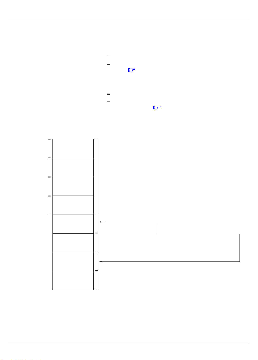
PORT ALLOCATION
The port allocation of the Time Division Switch is shown below:
• Number of ports for line/trunk cards 512 ports per system
“Number of Ports for Each Line/Trunk Card”. Page 34
See
• Number of ports for application processor cards
Basic AP port (Basic HW) 128 ports per system
Expanded AP port (Expanded HW) 128 ports per system
“Number of Ports for Each Application Processor Card”. Page 36
See
Port Allocation of Time Division Switch
<
128 ports per FP
<
<
<
CHAPTER 2 PRECAUTION
PORT ALLOCATION
128 ports/FP
128 ports/FP
128 ports/FP
128 ports/FP
128 ports
128 ports
128 ports
128 ports
128 ports
128 ports
128 ports
128 ports
Used for Line/Trunk (LT) Cards
128 ports per FP
512 ports per system
Used for Application Processor (AP) cards
256 ports per system
3-way conference (16 circuits), Music on Hold, Built-in MODEM,
DAT, DTMF Sender, DTMF Receiver, Audible tone (DTG), DK
Not Used
– 33 – NWA-008844-001 Rev.5.0
91ch2001.fm
NOVEMBER/15/2006

CHAPTER 2 PRECAUTION
Number of Ports for Each Line/Trunk Card
PORT ALLOCATION
L/T CARD
NUMBER OF
CIRCUITS
NUMBER OF
TIME SLOTS
PN-2AMPA (AMP) 2 4
PN-8COTH/PN-8COTQ/PN-8COTR/
PN-8COTS/PN-8COTT/PN-8COTU (COT)
88
PN-6COTJ (COT) 6 6
PN-4COTA-A/PN-4COTB/PN-4COTE/
PN-4COTF/PN-4COTG (COT)
44
PN-2COTD/PN-2COTE (COT) 2 2
PN-CFTA (CFT) 1 10
PN-CFTB (CFT) 1 10
PN-4CSIA/PN-4CSIA-A (CSI) 4 16
PN-2CSIA/PN-2CSIA-A/PN-2CSIH (CSI) 2 8
PN-4DATC (DAT) 4 8
PN-4DIDA (DIT) 4 4
PN-4DITB (DIT) 4 4
PN-2DITA (DIT) 2 2
REMARKS
PN-DK00 (DK) 8 0
PN-8DLCL/PN-8DLCP (DLC) 8 8
PN-4DLCM/PN-4DLCT/PN-4DLCQ (DLC) 4 4
PN-2DLCN (DLC) 2 2
PN-2ILCA (ILC) 2 8
PN-8IPLA (IP-PAD) 1
32 PN-8IPLA + PZ-24IPLA
PN-32IPLA/PN-32IPLA-A (IP-PAD) 1 32
PN-8LCAA/PN-8LCAB/PN-8LCAD/
PN-8LCAE/PN-8LCAF/PN-8LCAK (LC)
88
PN-4LCC/PN-4LCD-A/PN-4LCE/PN-4LCF/
PN-4LCK/PN-4LCL/PN-4LCV/PN-4LCW
44
(LC)
PN-4LLCB (LLC) 4 4
PN-4LDTA (LDT) 4 4
PN-2LDTA (LDT) 2 2
8 PN-8IPLA
Continued on next page
– 34 – NWA-008844-001 Rev.5.0
91ch2001.fm
NOVEMBER/15/2006

CHAPTER 2 PRECAUTION
Number of Ports for Each Line/Trunk Card
PORT ALLOCATION
L/T CARD
NUMBER OF
CIRCUITS
NUMBER OF
TIME SLOTS
PN-M10 (M10) 2 0
PN-M13 (M13) 24 0
PN-2ODTA/PN-2ODTB (ODT) 2 2
PN-4ODTA (ODT) 4 4
PN-8RSTG (PBR) 8 8
PN-4RSTF/PN-4RSTF-A (SDT) 4 4
PN-4RSTH (SDT) 4 4
PN-TNTA (TNT) 2 4
PN-16VCTA/PN-16VCTA-A (16VCT) 1 –
PN-4VCTI (4VCT) 1 –
PZ-8PFTB (PFT) 8 0
PZ-VM00 (VM00)/PZ-VM00-M (VM00) 1 4
PZ-VM01 (VM01) 4 4
PZ-VM02 (VM02) 1 4
PZ-VM03-M (VM03) 1 4
REMARKS
PZ-VM04 (VM04) 8 4
PZ-VM05 (VM05) 0 4
PZ-VM06 (VM06) 0 4
PZ-VM10-M (VM10) 1 4
– 35 – NWA-008844-001 Rev.5.0
91ch2001.fm
JULY/01/2006

CHAPTER 2 PRECAUTION
Number of Ports for Each Application Processor Card
×: Available –: Not available
PORT ALLOCATION
AP CARD
AP HIGHWAY
Basic HW
(128 time slots)
Expanded HW
(128 time slots)
NUMBER OF
TIME SLOTS/
CARD
PN-AP00-B (DBM) – – 0 For DBM
PN-AP00-B with AP00
× – 2 For SMDR/Hotel/MCI/PMS/CIS
program (AP00)
PN-AP00-B/PN-AP00-D
× – 2 For SMDR/Hotel/MCI/CIS
with MRCA program
(AP00)
PN-BRTA (BRT) × –2
PN-2BRTC (BRT) × –4
PN-2BRTK (BRT) × –4
PN-4BRTA-A (BRT) ××8
PN-24CCTA (CCT) ××25
PN-30CCTA (CCT) ××32
PN-CFTC (CFT) ××32
PN-CFTC-A (CFT) ××32
REMARKS
PN-CS00 (ATI) × – 1 For Large type ATTCON
PN-DAIA (DAIA) – – – Use FP Highway.
PN-DAIA-A (DAIA) – – – Use FP Highway.
PN-DAIB (DAIB) – – – Use FP Highway.
PN-DAIC (DAIC) – – – Use FP Highway.
PN-DAID (DAID) – – – Use FP Highway.
PN-DAID-A (DAID) – – – Use FP Highway.
PN-DAIE (DAIE) – – – Use FP Highway.
PN-DAIF (DAIF) – – – Use FP Highway.
PN-DTA (CCH) ××1
PN-DTA (CCT/PRT) ××25 For 24CCT/24PRT
32 For 30CCT/30PRT
PN-DTA (DTI) ××24 For 24DTI
31 For 30DTI
Continued on next page
– 36 – NWA-008844-001 Rev.5.0
91ch2001.fm
JUNE/01/2007

CHAPTER 2 PRECAUTION
Number of Ports for Each Application Processor Card
×: Available –: Not available
PORT ALLOCATION
AP CARD
AP HIGHWAY
Basic HW
(128 time slots)
Expanded HW
(128 time slots)
NUMBER OF
TIME SLOTS/
CARD
REMARKS
PN-DTB (CCH) ××1
PN-DTB (CCT/PRT) ××25 For 24CCT/24PRT
32 For 30CCT/30PRT
PN-DTB (DTI) ××24 For 24DTI
31 For 30DTI
PN-24DTA-A (DTI) × –24
PN-24DTA-C (DTI) ××24
PN-30DTC-A (DTI) × –31
PN-30DTC-C (DTI) ××31
PN-2ILCC (ILC) ××8
PN-8IPTA (SIP) × –8-32
PN-IPTB (IPT) – – 0 Not use Highway.
PN-24PRTA (PRT) ××25
PN-30PRTA (PRT) ××32
PN-4RSTB (MFR) × –4
PN-4RSTB-A (MFR) × –4
PN-4RSTC (CIR) × –4
PN-4RSTC-A (CIR) × –4
PN-SC00 (CCH) × –1
PN-SC01 (DCH) × –1
PN-SC03 (ICH) × –4
PN-SC03-A (CSH/ICH) × –4
PN-SC03-B (CSH/ICH) × –4
PN-SC03-C (CSH) × –4
– 37 – NWA-008844-001 Rev.5.0
91ch2001.fm
JUNE/01/2007

CHAPTER 2 PRECAUTION
PASSWORD ENTRY
PASSWORD ENTRY
In a system with password service, a maintenance person is required to enter a authorization level number
(Password Level) and appropriate password prior to engaging in programming the system data with the
MAT/CAT. A maximum of eight (8) Password Levels can be set up. The number of commands that the
maintenance person can access is determined by the Password Level.
Password and accessible commands for each Password Level is determined by system data.
The procedure for programming, with password, is shown below.
STEP1: Connect the MAT to the system, and turn the power switch on.
For the CAT, change the mode to CAT.
STEP2: Enter the password (assigned by CME9>0-7) by CM03.
Operation:
ST
+ 03 + + Password Level No. + +Password +
EXEDE DE
– “OK” will be displayed, if accepted.
In case of “DATA ERROR”, the password is incorrect.
STEP3: Start programming.
STEP4: When programming is completed, set the following data by CM03.
Operation:
ST DE DE
+ 03 + + 9 + + CCCCCCCC +
8 digits
EXE
– Programming without password is restricted.
NOTE: For the details of data assignment for password service, refer to CME7, CME9 on Chapter 3
Command Description.
– 38 – NWA-008844-001 Rev.5.0
91ch2001.fm

Table below shows the example for the Password Level Table.
Example of Password Level Assignment
CHAPTER 2 PRECAUTION
PASSWORD ENTRY
MAINTENANCE
PERSONNEL
A
B
C
D
E
F
NOTE: All Levels can access CM03.
PASS WORD
LEVEL
Level 7
Level 4
Level 3
Level 2
Level 1
Level 0
ACCESIBLE COMMANDS
All commands
CM05, 08-13, 15, 30, 35, 36
CM08-13, 15, 30, 35
CM10/14, 11, 30, 35
CM10/14, 11
CM10/14
– 39 – NWA-008844-001 Rev.5.0
91ch2001.fm

CHAPTER 2 PRECAUTION
NATION CODE ASSIGNMENT
NATION CODE ASSIGNMENT
With the Nation Code assigned, the system offers the particular services to the users of each country.
For Australia or New Zealand, appropriate nation code to the user should be assigned by CM31 Y=0 as
shown below.
• Users in Australia
ST DEDE
+ 310 + + 0 + + 01 +
EXE
• Users in New Zealand
ST DEDE
+ 310 + + 0 + + 15 +
EXE
NOTE 1: System reset is required after changing the command data.
NOTE 2: Initial data of CM31 Y=0>0 depends on each nation code of the MP program as follows:
For Australia/NZ : 01
For UK : 02
For North America : 03
For Asia/Africa/Europe/Latin America/Middle East/Russia : 04
NOTE 3: In case of EU, the initial data of CM31 Y=0>0 is same as North America (nation code 03).
Therefore, you must set the nation code to 04 by this command.
– 40 – NWA-008844-001 Rev.5.0
91ch2001.fm
NOVEMBER/15/2006

CHAPTER 2 PRECAUTION
SYSTEM DATA BACKUP
SYSTEM DATA BACKUP
CAUTION
• If you operate as follows without system data backup after system data setting or service
memory setting (registration of the features such as “Call Forwarding” and “Speed Calling
[Speed Dialing]” from a station), the data that has been set is invalid.
You must execute the system data backup before the following operations.
-Turning Off the system
-System Initialization (reset of MP card)
-Changing the MP card to Off-Line Mode
-Changing the MP card to On-Line Mode after system data setting under Off-Line Mode
• You can execute the system data backup by the following two ways.
-Executing the system data backup once a day at the time set by CM43 Y=5>00
(If no data is set, the default setting is 3:00 a.m.)
-Executing the system data backup from MAT/CAT by CMEC Y=6>0:0
• Do not reset the MP card while “SYSD” lamp on the MP card is flashing.
– 41 – NWA-008844-001 Rev.5.0
91ch2001.fm
DECEMBER/02/2005

THIS PAGE LEFT BLANK INTENTIONALLY.
– 42 – NWA-008844-001 Rev.5.0
91ch2001.fm
DECEMBER/02/2005

CHAPTER 3 COMMAND DESCRIPTION
CHAPTER 3
COMMAND DESCRIPTION
This chapter explains the function, precaution, assignment procedure and
data table of each command.
Explanations are given in numerical and alphabetical order of the command
code.
HOW TO READ THIS CHAPTER .............................................. 44
COMMAND DESCRIPTION ....................................................... 45
– 43 – NWA-008844-001 Rev.5.0
91ch3001.fm

CHAPTER 3 COMMAND DESCRIPTION
HOW TO READ THIS CHAPTER
HOW TO READ THIS CHAPTER
Information about each command is presented in the following order:
(1) FUNCTION: The function of the command.
(2) PRECAUTION: Precautions related to assigning data.
(3) ASSIGNMENT PROCEDURE: The procedure for assigning data in CAT mode.
(4) DATA TABLE: Detailed descriptions of the data.
In the description of each command, the following symbols are used.
: Initial data which is automatically loaded into the memory, after system initialization
by setting position “B” on SW3 of the MP, followed by a reset.
INITIAL
AP00 INITIAL
OFF LINE
AP OFF LINE
CSH INITIAL
DCH INITIAL
ICH INITIAL
DTI INITIAL
CFT INITIAL
IPT INITIAL
SIP INITIAL
IP-PAD INITIAL
: Commands which require a reset of the MP card after data setting.
: Commands which require a reset of the AP00 card after data setting.
: Commands which can be used only under Off-Line mode of the MP card.
To set Off-Line mode,
(1) Set SW3 on the MP card to “2” or “3”.
(2) Press SW1 on the MP card.
: Commands which can be used only under Off-Line mode of the AP00 card.
: Commands which require a reset of the CSH card after data setting.
: Commands which require a reset of the DCH card after data setting.
: Commands which require a reset of the ICH card after data setting.
: Commands which require a reset of the DTI/BRT/PRT/CCT card after data setting.
: Commands which require a reset of the CFTC card after data setting.
: Commands which require a reset of the IPT card after data setting.
: Commands which require a reset of the SIP card after data setting.
: Commands which require a reset of the IP-PAD card after data setting.
BRT INITIAL
CIR INITIAL
: Commands which require a reset of the BRT card after data setting.
: Commands which require a reset of the CIR card after data setting.
Refer to Chapter 4 for details on default data when the Resident System Program is loaded by setting position “C” on SW3 of the MP, followed by a reset.
You should confirm the meaning of initial data, and change or delete the data, if required.
– 44 – NWA-008844-001 Rev.5.0
91ch3001.fm
DECEMBER/02/2005

CM00
COMMAND CODE
00
TITLE:
SYSTEM DATA MEMORY ALL CLEAR
OFF LINE
FUNCTION:
This command is used to confirm that system data memory (RAM) area can be written-in/read-out, and
to assign the initial data to the RAM area.
PRECAUTION:
(1) This command can only be used in off-line mode.
(2) When this command is executed, “OK” is displayed with memory clear completed (about 10
seconds later).
(3) If an error exists in memory, “WD ERROR” is displayed.
(4) This command is not available with a CAT.
To clear all system data, set SW3 to “B”, and depress SW1 on the MP card. In this case, the only
functional port is LEN000/LEN00000, which is assigned as a CAT.
(5) After clearing all system data memory by CM00>1/11/12/13/14, the initial data of CM05 is set
according to the table on next page.
– 45 – NWA-008844-001 Rev.5.0
91ch3001.fm

CM00
COMMAND CODE
00
Clear
Command
CM05
CM05
Y=0
(Setting
of FP/AP
Card
Type)
FP/AP No. Card Type (NONE: No data)
TITLE:
SYSTEM DATA MEMORY ALL CLEAR
CM00>11
CM00>1
(8 PIMs)
00 00 (FP) 00 (FP) 00 (FP) 00 (FP) 00 (FP)
01 00 (FP) 00 (FP) 00 (FP) 00 (FP) 00 (FP)
02 00 (FP) 00 (FP) 00 (FP) 00 (FP) 00 (FP)
03 00 (FP) 00 (FP) 00 (FP) 00 (FP) 00 (FP)
16 NONE 00 (FP) NONE NONE NONE
17 NONE 00 (FP) 00 (FP) 00 (FP) NONE
18 NONE 00 (FP) 00 (FP) 00 (FP) 00 (FP)
19 NONE 00 (FP) 00 (FP) 00 (FP) 00 (FP)
(1 PIM +
7 Virtual
PIMs)
CM00>12
(2 PIMs +
6 Virtual
PIMs)
CM00>13
(3 PIMs +
5 Virtual
PIMs)
OFF LINE
CM00>14
(4 PIMs +
4 Virtual
PIMs)
CM05
Y=4
(PIM No.
controlled by
each FP/
PIM No.
accommodates
Virtual
IPT)
04-15,
20-59
60-63 00 (Virtual FP
FP/AP No. PIM No./Virtual PIM No. (NONE: See
00 NONE 00 (PIM0) NONE NONE NONE
01 NONE 02 (PIM2) 02 (PIM2) 02 (PIM2) NONE
02 NONE 04 (PIM4) 04 (PIM4) 04 (PIM4) 04 (PIM4)
03 NONE 06 (PIM6) 06 (PIM6) 06 (PIM6) 06 (PIM6)
16 NONE 01 (PIM1) NONE NONE NONE
17 NONE 03 (PIM3) 03 (PIM3) 03 (PIM3) NONE
18 NONE 05 (PIM5) 05 (PIM5) 05 (PIM5) 05 (PIM5)
19 NONE 07 (PIM7) 07 (PIM7) 07 (PIM7) 07 (PIM7)
04-15,
20-63
NONE NONE NONE NONE NONE
00 (Virtual FP
for PS Station)
NONE NONE NONE NONE NONE
for PS Station)
00 (Virtual FP
for PS Station)
00 (Virtual FP
for PS Station)
NOTE 3.)
00 (Virtual FP
for PS Station)
Continued on next page
– 46 – NWA-008844-001 Rev.5.0
91ch3001.fm

CM00
COMMAND CODE
00
Clear
Command
CM05
CM05
Y=6
(Type of
FP/AP)
NOTE 1
NOTE 2
FP/AP No. Type of FP/AP (NONE: No data)
TITLE:
SYSTEM DATA MEMORY ALL CLEAR
CM00>11
CM00>1
(8 PIMs)
00 2 (Built-in
FP)
01 NONE 0 (Virtual FP) 0 (Virtual FP) 3 (PN-CP15) 3 (PN-CP15)
02 NONE 0 (Virtual FP) 0 (Virtual FP) 0 (Virtual FP) 0 (Virtual FP)
03 NONE 0 (Virtual FP) 0 (Virtual FP) 0 (Virtual FP) 0 (Virtual FP)
16 NONE 0 (Virtual FP) 3 (PN-CP15) 3 (PN-CP15) 3 (PN-CP15)
17 NONE 0 (Virtual FP) 0 (Virtual FP) 0 (Virtual FP) 3 (PN-CP15)
18 NONE 0 (Virtual FP) 0 (Virtual FP) 0 (Virtual FP) 0 (Virtual FP)
(1 PIM +
7 Virtual
PIMs)
2 (Built-in
FP)
CM00>12
(2 PIMs +
6 Virtual
PIMs)
2 (Built-in
FP)
CM00>13
(3 PIMs +
5 Virtual
PIMs)
2 (Built-in
FP)
OFF LINE
CM00>14
(4 PIMs +
4 Virtual
PIMs)
2 (Built-in
FP)
CM05
Y=8
(Site No.
+
PIM No.
controlled by
each FP/
PIM No.
accommodates
Virtual
IPT)
19 NONE 0 (Virtual FP) 0 (Virtual FP) 0 (Virtual FP) 0 (Virtual FP)
04-15,
20-63
FP/AP No. PIM No./Virtual PIM No. (NONE: See
00 NONE 0000 (PIM0) NONE NONE NONE
01 NONE 0002 (PIM2) 0002 (PIM2) 0002 (PIM2) NONE
02 NONE 0004 (PIM4) 0004 (PIM4) 0004 (PIM4) 0004 (PIM4)
03 NONE 0006 (PIM6) 0006 (PIM6) 0006 (PIM6) 0006 (PIM6)
16 NONE 0001 (PIM1) NONE NONE NONE
17 NONE 0003 (PIM3) 0003 (PIM3) 0003 (PIM3) NONE
18 NONE 0005 (PIM5) 0005 (PIM5) 0005 (PIM5) 0005 (PIM5)
19 NONE 0007 (PIM7) 0007 (PIM7) 0007 (PIM7) 0007 (PIM7)
04-15,
20-63
NONE 3 (AP Card) 3 (AP Card) 3 (AP Card) 3 (AP Card)
NOTE 3)
NONE NONE NONE NONE NONE
Continued on next page
– 47 – NWA-008844-001 Rev.5.0
91ch3001.fm

CM00
COMMAND CODE
00
TITLE:
SYSTEM DATA MEMORY ALL CLEAR
OFF LINE
NOTE 1: MP Built-in FP is used for controlling Legacy line/trunk cards. Only FP No. 00 is available.
NOTE 2: Virtual FP is used for controlling Peer-to-Peer connection between D
term
IPs on intra-office
and via CCIS.
NOTE 3: CM05 Y=4/8 NONE data are as follows.
FP No. 00: PIM0 and PIM1
FP No. 01: PIM2 and PIM3
FP No. 02: PIM4 and PIM5
FP No. 03: PIM6 and PIM7
FP No. 04-63: No data
AP No. 04-15, 20-63: No data
ASSIGNMENT PROCEDURE:
MEMORY AREA
+00+ +
ST
DESIGNATION
++ +
DEDE
CCC
EXE
(1/2 digits)
DATA TABLE:
1ST DATA 2ND DATA
DATA MEANING DATA MEANING
1 System data memory all clear for the TDSW-
based PBX system (8 PIMs)
11 System data memory all clear for the IP-
based PBX system (1 PIM + 7 Virtual PIMs)
12 System data memory all clear for the IP-
based PBX system (2 PIMs + 6 Virtual
PIMs)
13 System data memory all clear for the IP-
based PBX system (3 PIMs + 5 Virtual
PIMs)
14 System data memory all clear for the IP-
based PBX system (4 PIMs + 4 Virtual
PIMs)
CCC Clear
CCC Clear
CCC Clear
CCC Clear
CCC Clear
Continued on next page
– 48 – NWA-008844-001 Rev.5.0
91ch3001.fm

CM00
COMMAND CODE
00
DATA MEANING DATA MEANING
90 Execute the office data conversion
[Series 3200 R6.2 (R6.2)]
NOTE 1:
NOTE 2: When first data “90” is typed, second data “1” is displayed. Also while converting the office
NOTE 3: There is no problem even if the office data conversion is executed again and again.
TITLE:
SYSTEM DATA MEMORY ALL CLEAR
1ST DATA 2ND DATA
0
1
When upgrading the software of the system from Series 3300 or before to Series 3400 or later
this data is required.
data, “1” is displayed.
Start converting
Always displayed after first data “90” is
typed
OFF LINE
NOTE 2
– 49 – NWA-008844-001 Rev.5.0
91ch3001.fm
JULY/01/2006

CM01
COMMAND CODE
01
TITLE:
SYSTEM DATA MEMORY PARTIAL CLEAR
OFF LINE
FUNCTION:
This command is used to clear the data for specific features.
PRECAUTION:
This command can only be used in off-line mode.
ASSIGNMENT PROCEDURE:
ST
++ ++01
DE
CLEAR DESIGNATION
(2 digits)
DE
++
CCC
EXE
DATA TABLE:
CLEAR DESIGNATION SYSTEM DATA TO BE CLEARED REMARKS
08 CM08: Basic Service Feature
20 CM20: Numbering Plan
CM21: Single Digit Access Code
CM22: Route Advance
CM23: Tenant Development
CM25: Kind of Special Terminal Development
CM29: Numbering Plan Tenant Group
2A CM2A: ID Code Assignment with MP
76 CM76: Digit Conversion on DID Call
85 CM85: Maximum Digits on C.O. Calls
8A CM8A: LCR/Toll Restriction Development Table
– 50 – NWA-008844-001 Rev.5.0
91ch3001.fm

CM02
COMMAND CODE
TITLE:
SETTING OF SYSTEM CLOCK/READING OUT OF DAYLIGHT
02
SAVING TIME
FUNCTION:
This command is used to assign system clock data (year, date and time). And this command is used to
read out of the daylight saving time.
PRECAUTION:
The system clock starts when is pressed.
EXE
ASSIGNMENT PROCEDURE:
(1) Setting of System Clock
ST
++ +
DE02
1ST DATA
(0-2) (4/6 digits)
DE
+
2ND DATA
++
EXE
(2) Reading out of Daylight Saving Time
ST
++
DE02
1ST DATA
(3)
DE
+
2ND DATA
++
– 51 – NWA-008844-001 Rev.5.0
91ch3001.fm
DECEMBER/02/2005

CM02
COMMAND CODE
TITLE:
SETTING OF SYSTEM CLOCK/READING OUT OF DAYLIGHT
02
SAVING TIME
DATA TABLE:
1ST DATA 2ND DATA
DATA MEANING DATA MEANING
0 Setting of Calendar Year YYYY Calendar Year
YYYY: Year (2000-2099)
1 Setting of Date (Month, Day, Day of Week) MMDDWW Date
MM: Month (01-12)
DD : Day (01-31)
WW: Day of Week (00-06)
SUN : 00 THU: 04
MON: 01 FRI : 05
TUE : 02 SAT : 06
WED: 03
2 Setting of Time (Hour, Minute, Second)
“Hour” information is set in military format
(24-hour)
Example: 2 p.m. is set as “140000”.
HHMMSS Time
HH : Hour (00-23)
MM: Minute (00-59)
SS : Second (00-59)
3 Reading out of Daylight Saving Time in Main
Site
[Series 3600]
HH:MM:SS Daylight Saving Time
HH : Hour (00-23)
MM: Minute (00-59)
SS : Second (00-59)
– 52 – NWA-008844-001 Rev.5.0
91ch3001.fm
DECEMBER/02/2005

CM03
COMMAND CODE
03
TITLE:
LOG IN/LOG OUT OF PASSWORD MODE
FUNCTION:
This command is used to enter a password which allows the authorized personnel to access commands
in accordance with preassigned authorization levels.
PRECAUTION:
(1) The password for each level is set by CME9.
The accessible commands for each level is set by CME7.
(2) “OK” is displayed when the log in is successful.
(3) For security purpose, when a password is entered, “*” is displayed.
(4) The password mode is automatically logged out unless a command is entered within 10 minutes
after logging in.
ASSIGNMENT PROCEDURE:
To log in the password mode and enter the password
++ ++
ST
03
DE
PASSWORD LEVEL
(0-7) (Maximum 8 digits)
DE
To log off the password mode
+++
ST
03
DE
9
DE
++
CCCCCCCC
+
PASSWORD
++
EXE
EXE
– 53 – NWA-008844-001 Rev.5.0
91ch3001.fm

CM04
COMMAND CODE
04
TITLE:
LANGUAGE INDICATED ON D
term
/ATTCON/DESKCON LCD,
PURPOSE OF CALLER ID SENDER, CONNECTION PORT FOR MCI
FUNCTION:
This command selects the language that is displayed on the D
term
/ATTCON/DESKCON LCDs, the pur-
pose of the Caller ID sender, and the connection port for MCI (Message Center Interface).
PRECAUTION:
None
ASSIGNMENT PROCEDURE:
ST
04YY
DE
1ST DATA
(2 digits) (1/2 digits)
DE
+
2ND DATA
++
EXE++ +
– 54 – NWA-008844-001 Rev.5.0
91ch3001.fm

CM04
COMMAND CODE
TITLE:
LANGUAGE INDICATED ON D
04
PURPOSE OF CALLER ID SENDER, CONNECTION PORT FOR MCI
DATA TABLE:
Y
DATA MEANING DATA MEANING
00 00 Display language for D
1ST DATA 2ND DATA
ATTCON/DESKCON LCD
(System Base)
term
/
INITIAL
00
01
02
03
04
05
06
07
08
09
10
11
12
13
31
term
/ATTCON/DESKCON LCD,
0
Japanese
English
1
French
2
3
Spanish
4
Portuguese
5
German
Italian
6
English
7
[Series 3200 R6.2 (R6.2) or
before]
Japanese
English
French (Canadian French)
Spanish (Latin Spanish)
Portuguese (Brazilian Portuguese)
German
Italian
Netherlandish
French (Europe)
Spanish (Europe)
Portuguese (Europe)
Swedish
Danish
Catalan (Europe)
[Series 3800]
English
[Series 3300 or later]
: Initial Data
RELATED
COMMAND
NOTE:
When using Series 3600 software or later, a reset of the MP card is not required. When changing the data
with online, the data is valid after the DLC card is unplugged and plugged in or pull out and reconnect the
modular connector of the D
term
.
Continued on next page
– 55 – NWA-008844-001 Rev.5.0
91ch3001.fm
JUNE/01/2007

CM04
COMMAND CODE
04
Y
DATA MEANING DATA MEANING
00 01 DTG for D
(System-basis)
[Series 3200 R6.2 (R6.2)]
TITLE:
LANGUAGE INDICATED ON D
term
/ATTCON/DESKCON LCD,
PURPOSE OF CALLER ID SENDER, CONNECTION PORT FOR MCI
: Initial Data
1ST DATA 2ND DATA
term
IP
01
02
03
04
05
06
07
08
09
10
11
13
14
15
16
17
18
19
20
21
22
23
24
25
26
27
NONE
Japan
North America
Australia
A-law countries
Hong Kong
Malaysia
Singapore
UK
Mexico
Taiwan
New Zealand
China
Thailand
Brazil
Netherlands
Germany
Italy
Austria
Belgium
Spain
Sweden
UK
Denmark
Greece
Switzerland
South Africa
Not used
For EU
RELATED
COMMAND
CM67 Y=13
Continued on next page
– 56 – NWA-008844-001 Rev.5.0
91ch3001.fm
NOVEMBER/15/2006

CM04
COMMAND CODE
TITLE:
LANGUAGE INDICATED ON D
04
Y
DATA MEANING DATA MEANING
01 01 Connection port for MCI 0
02 Purpose of Caller ID sender
(PN-4RSTF/PN-4RSTF-A/
PN-4RSTH)
[North America/EU]
03 Destination to send an MP call
information
[Series 3300]
PURPOSE OF CALLER ID SENDER, CONNECTION PORT FOR MCI
1ST DATA 2ND DATA
term
/ATTCON/DESKCON LCD,
RS0 on MP
1
RS1 on MP
2
PN-AP00-B/PN-AP00-D with
MRCA program
[Series 3300]
PN-AP00-B with AP00 program
7
0
Caller ID-Station
7
No data
2
PN-AP00-B/PN-AP00-D with
MRCA program
7
Not sent
: Initial Data
RELATED
COMMAND
CM08>507
CM10/
CM14>C2XX
CM45 Y=5
CM50 Y=00>8
05 Destination to send a Built-in
SMDR call information
[Series 3400]
06 Destination to send a call informa-
tion which received from Local
Office
[Series 3400]
07 SMDR Message Format of Built-in
SMDR on RS-232C and Local
Office for Centralized BillingCCIS
[Series 3400]
08 SMDR Message Format of Built-in
SMDR on IP
[Series 3400]
00
15
00
15
0
SMDR terminal via LAN port
1
PMS via LAN port
7
SMDR terminal via RS port
0
SMDR terminal via LAN port
3
PN-AP00-B/PN-AP00-D with
MRCA program
(CM04 Y=01>03: 2)
PN-AP00-B with AP00
program (CM04 Y=01>03: 7)
Extended NEAX 2400 IMS Format
Former NEAX 2400 IMS Format
Extended NEAX 2400 IMS Format
Former NEAX 2400 IMS Format
CM04 Y=01>03
Continued on next page
– 57 – NWA-008844-001 Rev.5.0
91ch3001.fm
NOVEMBER/15/2006

CM04
COMMAND CODE
TITLE:
LANGUAGE INDICATED ON D
04
Y
DATA MEANING DATA MEANING
01 09 SMDR Message Format of Center
Office for Centralized BillingCCIS
[Series 3400]
10 Control method for PMS
[Series 3400]
10 00 A-law/µ-law for the Main Site
[For EU]
[Series 3200 R6.2 (R6.2)]
PURPOSE OF CALLER ID SENDER, CONNECTION PORT FOR MCI
1ST DATA 2ND DATA
00
15
term
/ATTCON/DESKCON LCD,
Extended NEAX 2400 IMS Format
Former NEAX 2400 IMS Format
0
MP
1
PN-AP00-B/PN-AP00-D with
MRCA program
3
PN-AP00-B with AP00 program
0
A-law
1
µ-law
Not used
2
3
Depends on the SW2-1 on PNCP24-A/PN-CP24-B/PN-CP24-C/
PN-CP24-D/PN-CP27-A/PNCP27-B or the Key ROM (SP-3722
IPS KYUS PROG-A1) on PNCP31-A/PN-CP31-B/PN-CP31-C/
PN-CP31-D
: Initial Data
RELATED
COMMAND
NOTE 1: When using PN-CP24-A/PN-CP24-B/PN-CP24-C/PN-CP24-D/PN-CP27-A/PN-CP27-B, set the 2nd
data to 3 and set the A-law/µ-law by the SW2-1.
NOTE 2: When using PN-CP31-A/PN-CP31-B/PN-CP31-C/PN-CP31-D, the system is set to µ-law automatically.
Set the 2nd data to 0 for A-law.
NOTE 3: Set the same value as Remote Site (CM04 Y=11-25). You cannot set both of A-law and µ-law in the same
Remote PIM over IP.
NOTE 4: When CM04 Y=10>00 is set to 3, A-law/µ-law setting is decided in the following order.
1. Setting by Key ROM
2. Setting of SW2-1 of the MP
Continued on next page
– 58 – NWA-008844-001 Rev.5.0
91ch3001.fm
JUNE/01/2007

CM04
COMMAND CODE
04
Y
DATA MEANING DATA MEANING
11
~
40
00 A-law/µ-law for the Remote Site
Y=11: Remote Site No. 01
Y=40: Remote Site No. 30
[For EU]
[Series 3200 R6.2 (R6.2)]
NOTE 1: When using PN-CP24-A/PN-CP24-B/PN-CP24-C/PN-CP24-D/PN-CP27-A/PN-CP27-B, set the 2nd
data to 3 and set the A-law/µ-law by the SW2-1.
NOTE 2: When using PN-CP31-A/PN-CP31-B/PN-CP31-C/PN-CP31-D, the system is set to µ-law automatically.
Set the 2nd data to 0 for A-law.
NOTE 3: Set the same value as Main Site (CM04 Y=10). You cannot set both of A-law and µ-law in the same Re-
mote PIM over IP.
NOTE 4: When CM04 Y=10>00 is set to 3, A-law/µ-law setting is decided in the following order.
1. Setting by Key ROM
2. Setting of SW2-1 of the MP
TITLE:
LANGUAGE INDICATED ON D
term
/ATTCON/DESKCON LCD,
PURPOSE OF CALLER ID SENDER, CONNECTION PORT FOR MCI
1ST DATA 2ND DATA
0
A-law
1
~
µ-law
2
Not used
Depends on the SW2-1 on PN-
3
CP24-A/PN-CP24-B/PN-CP24-C/
PN-CP24-D/PN-CP27-A/PNCP27-B or the Key ROM (SP-3722
IPS KYUS PROG-A1) on PNCP31-A/PN-CP31-B/PN-CP31-C/
PN-CP31-D
: Initial Data
RELATED
COMMAND
– 59 – NWA-008844-001 Rev.5.0
91ch3001.fm
NOVEMBER/15/2006

CM05
COMMAND CODE
05
TITLE:
AP/FP CARD TYPE, HIGHWAY CHANNEL
INITIAL
FUNCTION:
This command is used to designate the type of application processor (AP)/firmware processor (FP) card
installed.
PRECAUTION:
(1) This command requires a system reset after data setting.
(2) The available value of first data of CM05 (FP/AP number) depends on the software version used
in the system.
Assign the correct FP/AP number to each FP/AP, referring to tables below.
[For Series 3200 R6.1 software or before]
×: Available –: Not available
FP/AP No.
FP/AP TYPE
FP card (PN-CP15) – × – × –––
MP built-in FP × ––––––
DAIA/DAID card – × – × –––
Virtual FP for D
AP card – – × – × ––
Virtual AP (Virtual IPT) – – × – × ––
term
IP – × – × –––
00 01-03 04-15 16-19 20-31 32-59 60-63
[For Series 3200 R6.2 software]
×: Available –: Not available
FP/AP No.
FP/AP TYPE
FP card (PN-CP15) – × – × –––
MP built-in FP × ––––––
Virtual FP for D
AP card – – × – × ––
Virtual AP (Virtual IPT) – – × – × ––
term
IP – ××××––
00 01-03 04-15 16-19 20-31 32-59 60-63
Continued on next page
– 60 – NWA-008844-001 Rev.5.0
91ch3001.fm

CM05
COMMAND CODE
05
TITLE:
AP/FP CARD TYPE, HIGHWAY CHANNEL
INITIAL
• For Remote PIM over IP
×: Available –: Not available
FP/AP No.
FP/AP TYPE
FP card (PN-CP15) – × – × –––
MP built-in FP Main Site × ––––––
Remote Site – ××××––
Virtual FP for
term
D
IP
AP card – – × – × ––
Virtual AP (Virtual IPT) – – × – × ––
Main Site/
Remote Site
00 01-03 04-15 16-19 20-31 32-59 60-63
– ××××––
[For Series 3300 software]
×/∆: Available NOTE –: Not available
FP/AP No.
FP/AP TYPE
FP card (PN-CP15) – × – × –––
MP built-in FP × ––––––
Virtual FP for D
AP card – – × – × ––
Virtual AP (Virtual IPT/Virtual
[For PHS])
CSH
Virtual FP for PS Station – ∆ ––––×
term
IP – ×∆×∆∆–
00 01-03 04-15 16-19 20-31 32-59 60-63
––∆ – ∆×–
NOTE: Although FP/AP number marked with “∆” is available to use, we recommend FP/AP num-
ber marked with “
×
”.
Continued on next page
– 61 – NWA-008844-001 Rev.5.0
91ch3001.fm

CM05
COMMAND CODE
05
TITLE:
AP/FP CARD TYPE, HIGHWAY CHANNEL
INITIAL
• For Remote PIM over IP
×/∆: Available
FP/AP No.
FP/AP TYPE
FP card (PN-CP15) – × – × –––
MP built-in FP Main Site × ––––––
Remote Site – ∆∆∆∆× –
Virtual FP for
term
D
IP
AP card – – × – × ––
Virtual AP (Virtual IPT/Virtual
[For PHS])
CSH
Virtual FP for PS Station – ∆ ––––×
Main Site – ×∆×∆∆–
Remote Site – ∆∆∆∆× –
00 01-03 04-15 16-19 20-31 32-59 60-63
––∆ – ∆×–
NOTE 1 –: Not available
[For Series 3400/3500/3600/3700 software]
×/∆: Available NOTE 1 –: Not available
FP/AP No.
FP/AP TYPE
FP card (PN-CP15) – × – × –––
MP built-in FP × ––––––
Virtual FP for D
AP card – – × – × ––
Virtual AP (Virtual IPT/Virtual
CSH for IP-CS
Virtual CSH for WLAN)
Virtual FP for PS Station/
Virtual FP for WLAN Station
term
IP – ×∆×∆∆–
[For PHS]/
NOTE 3
NOTE 3
00 01-03 04-15 16-19 20-31 32-59 60-63
––∆ – ∆×–
– ∆ –––×
NOTE 2
×
NOTE 1: Although FP/AP number marked with “∆” is available to use, we recommend FP/AP num-
ber marked with “×”.
NOTE 2: We recommend the setting of the FP number (60-63), when providing 256 PS stations/
WLAN stations or less and setting of the FP number (56-63), when providing 257 PS stations/WLAN stations or more.
NOTE 3: Virtual CSH for WLAN and Virtual FP for WLAN Station are available for Series 3600 soft-
ware or later.
Continued on next page
– 62 – NWA-008844-001 Rev.5.0
91ch3001.fm
NOVEMBER/15/2006

CM05
COMMAND CODE
05
TITLE:
AP/FP CARD TYPE, HIGHWAY CHANNEL
INITIAL
• For Remote PIM over IP
×/∆: Available
FP/AP No.
FP/AP TYPE
FP card (PN-CP15) – × – × –––
MP built-in FP Main Site × ––––––
Remote Site – ∆∆∆∆× –
Virtual FP for
term
D
IP/
Virtual FP for
User Mobility
NOTE 3
AP card – – × – × ––
Virtual AP (Virtual IPT/Virtual
CSH for IP-CS
Virtual CSH for WLAN)
Virtual FP for PS Station/
Virtual FP for WLAN Station
Main Site – ×∆×∆∆–
Remote Site – ∆∆∆∆× –
[For PHS]/
NOTE 4
NOTE 4
00 01-03 04-15 16-19 20-31 32-59 60-63
––∆ – ∆×–
– ∆ –––×
NOTE 1 –: Not available
×
NOTE 2
NOTE 1: Although FP/AP number marked with “∆” is available to use, we recommend FP/AP num-
ber marked with “×”.
NOTE 2: We recommend the setting of the FP number (60-63), when providing 256 PS stations or less
and setting of the FP number (56-63), when providing 257 PS stations or more.
NOTE 3: Virtual FP for user mobility is available for Series 3500 software or later.
NOTE 4: Virtual CSH for WLAN and Virtual FP for WLAN Station are available for Series 3600 soft-
ware or later.
Continued on next page
– 63 – NWA-008844-001 Rev.5.0
91ch3001.fm
NOVEMBER/15/2006

CM05
COMMAND CODE
05
TITLE:
AP/FP CARD TYPE, HIGHWAY CHANNEL
INITIAL
[For Series 3800 software or later]
×/∆: Available NOTE 1 –: Not available
FP/AP No.
FP/AP TYPE
FP card (PN-CP15) – × – × ––––
MP built-in FP × –––––––
Virtual FP for D
AP card – – × – × –––
Virtual AP (Virtual IPT/Virtual
CSH for IP-CS
Virtual CSH for WLAN)
Virtual FP for PS Station/
Virtual FP for WLAN Station
term
IP – ×∆×∆∆––
[For PHS]/
00 01-03 04-15 16-19 20-31 32-59 60-63 64-93
––∆ – ∆×––
– ∆ –––×
NOTE 2
× –
NOTE 1: Although FP/AP number marked with “∆” is available to use, we recommend FP/AP num-
ber marked with “×”.
NOTE 2: We recommend the setting of the FP number (60-63), when providing 256 PS stations/
WLAN stations or less and setting of the FP number (56-63), when providing 257 PS stations/WLAN stations or more.
Continued on next page
– 64 – NWA-008844-001 Rev.5.0
91ch3001.fm
NOVEMBER/15/2006

CM05
COMMAND CODE
05
TITLE:
AP/FP CARD TYPE, HIGHWAY CHANNEL
INITIAL
• For Remote PIM over IP
×/∆: Available
FP/AP No.
FP/AP TYPE
FP card (PN-CP15) – × – × ––––
MP built-in FP Main Site × –––––––
Remote Site – ∆∆∆∆×––
Virtual FP for
term
D
IP/
Virtual FP for
User Mobility
AP card Main Site – – × – × –––
Virtual AP (Virtual IPT/Virtual
CSH for IP-CS
Virtual CSH for WLAN)
Virtual FP for PS Station/
Virtual FP for WLAN Station
Main Site – ×∆×∆∆––
Remote Site – ∆∆∆∆×––
Remote Site – – × – × ––◊
[For PHS]/
00 01-03 04-15 16-19 20-31 32-59 60-63 64-93
––∆ – ∆×––
– ∆ –––×
NOTE 1 –: Not available ◊: Available only for partial APs
NOTE 3
× –
NOTE 2
NOTE 1: Although FP/AP number marked with “∆” is available to use, we recommend FP/AP num-
ber marked with “×”.
NOTE 2: We recommend the setting of the FP number (60-63), when providing 256 PS stations or less
and setting of the FP number (56-63), when providing 257 PS stations or more.
NOTE 3: Only PRT and CIR (PN-4RSTC-A) cards accommodated in Remote Site are able to be used.
Continued on next page
– 65 – NWA-008844-001 Rev.5.0
91ch3001.fm
NOVEMBER/15/2006

CM05
COMMAND CODE
05
TITLE:
AP/FP CARD TYPE, HIGHWAY CHANNEL
(3) The AP numbers available for each AP card are as follows:
×: Available –: Not available
AP CARD AP No. 04-15 AP No. 20-31 REMARKS
PN-AP00-A (DBM) × –
PN-AP00-B (AP00/DBM) ××
PN-AP00-D (AP00) ××
PN-BRTA (BRT) × –
PN-2BRTC (BRT) ××
PN-2BRTK (BRT) ××
PN-4BRTA-A (BRT) ××
PN-24CCTA (CCT) ××
PN-30CCTA (CCT) ××
PN-CFTC (CFT) ××
PN-CFTC-A (CFT) ××
INITIAL
PN-CS00 (ATI) × – For Large type ATTCON
PN-DAIA (DAIA) – – Use FP No. 01-03.
PN-DAIA-A (DAIA) – – Use FP No. 01-03, 16-19.
PN-DAIB (DAIB) – – Use FP No. 00.
PN-DAIC (DAIC) – – Does not need AP number.
PN-DAID (DAID) – – Use FP No. 01-03.
PN-DAID-A (DAID) – – Use FP No. 01-03, 16-19.
PN-DAIE (DAIE) – – Use FP No. 00.
PN-DAIF (DAIF) – – Does not need AP number.
PN-DTA (CCH/CCT/DTI/
PRT)
PN-DTB (CCH/CCT/DTI/
PRT)
PN-24DTA-A (DTI) ××
PN-24DTA-C (DTI) ××
PN-30DTC-A (DTI) ××
××
××
Continued on next page
– 66 – NWA-008844-001 Rev.5.0
91ch3001.fm
JUNE/01/2007

CM05
COMMAND CODE
05
AP CARD AP No. 04-15 AP No. 20-31 REMARKS
PN-30DTC-C (DTI) ××
PN-2ILCC (ILC) ××
PN-8IPTA (SIP) ××
PN-IPTB (IPT) ××
PN-24PRTA (PRT) ××
PN-30PRTA (PRT) ××
PN-4RSTB (MFR) ××
PN-4RSTB-A (MFR) ××
PN-4RSTC (CIR) × –
PN-4RSTC-A (CIR) × –
PN-SC00 (CCH) ××
TITLE:
AP/FP CARD TYPE, HIGHWAY CHANNEL
×: Available –: Not available
INITIAL
PN-SC01 (DCH) ××
PN-SC03 (ICH) × –
PN-SC03-A (CSH/ICH) ××
PN-SC03-B (CSH/ICH) ××
PN-SC03-C (CSH) ××
Continued on next page
– 67 – NWA-008844-001 Rev.5.0
91ch3001.fm
JUNE/01/2007

CM05
COMMAND CODE
05
TITLE:
AP/FP CARD TYPE, HIGHWAY CHANNEL
INITIAL
(4) The SENSE and changeover switch on each AP card should be set to the AP number assigned by
this command as follows.
• PN-AP00-A, PN-BRTA, PN-CS00, PN-4RSTC, PN-4RSTC-A, PN-SC03 are set as follows:
SENSE SWITCH 456789ABCDEF
AP No.
04 05 06 07 08 09 10 11 12 13 14 15
• PN-AP00-B, PN-AP00-D, PN-2BRTC, PN-2BRTK, PN-4BRTA-A, PN-CFTC, PN-CFTC-A,
PN-24CCTA, PN-30CCTA, PN-DTA, PN-DTB, PN-24DTA-A, PN-24DTA-C, PN-30DTC-A,
PN-30DTC-C, PN-8IPTA, PN-IPTB, PN-24PRTA, PN-30PRTA, PN-4RSTB, PN-4RSTB-A,
PN-SC00, PN-SC01, PN-SC03-A, PN-SC03-B, PN-SC03-C are set as follows:
SENSE SWITCH 456789ABCDEF
AP No. Changeover SW is
ON
Changeover SW is
OFF
04 05 06 07 08 09 10 11 12 13 14 15
20 21 22 23 24 25 26 27 28 29 30 31
Continued on next page
– 68 – NWA-008844-001 Rev.5.0
91ch3001.fm
JUNE/01/2007

CM05
COMMAND CODE
05
AP CARD Changeover SW
PN-AP00-B SW1-4
PN-AP00-D SW1-4
PN-2BRTC SW11-4
PN-2BRTK SW11-4
PN-4BRTA-A SW4-8
PN-24CCTA SW1-4
PN-30CCTA SW-8
PN-CFTC SW1-4
PN-CFTC-A SW1-4
PN-DTA SW1-4
PN-DTB SW1-4
PN-24DTA-A SW-8
PN-24DTA-C SW1-4
PN-30DTC-A SW-8
PN-30DTC-C SW-8
PN-2ILCC SW2-8
PN-8IPTA SW0-4
PN-IPTB SW1-4
PN-24PRTA SW1-4
PN-30PRTA SW-8
PN-4RSTB SW-8
PN-SC00 SW0-4
PN-SC01 SW0-4
PN-SC03-A SW1-4
PN-SC03-B SW1-4
PN-SC03-C SW1-4
TITLE:
AP/FP CARD TYPE, HIGHWAY CHANNEL
ON : AP No. 04-15
OFF: AP No. 20-31
INITIAL
Continued on next page
– 69 – NWA-008844-001 Rev.5.0
91ch3001.fm
JUNE/01/2007

CM05
COMMAND CODE
05
TITLE:
AP/FP CARD TYPE, HIGHWAY CHANNEL
INITIAL
(5) The AP Highway channel available for each AP card and the number of time slots per card are
shown below.
×: Available –: Not available
AP HIGHWAY
AP CARD
PN-AP00-A/PN-AP00-B
(DBM)
PN-AP00-B/PN-AP00-D
(AP00)
PN-BRTA (BRT) × –2
PN-2BRTC (BRT) × –4
PN-2BRTK (BRT) × –4
PN-4BRTA-A (BRT) ××8
PN-24CCTA (CCT) ××25
Basic HW
(128 time slots)
– – 2 For DBM
× – 2 For SMDR/Hotel/CIS
Expanded HW
(128 time slots)
NUMBER OF
TIME SLOTS
/CARD
REMARKS
PN-30CCTA (CCT) ××32
PN-CFTC (CFT) ××32
PN-CFTC-A (CFT) ××32
PN-CS00 (ATI) × – 1 For Large type ATTCON
PN-DAIA (DAIA) – – – Use FP Highway.
PN-DAIA-A (DAIA) – – – Use FP Highway.
PN-DAIB (DAIB) – – – Use FP Highway.
PN-DAIC (DAIC) – – – Use FP Highway.
PN-DAID (DAID) – – – Use FP Highway.
PN-DAID-A (DAID) – – – Use FP Highway.
PN-DAIE (DAIE) – – – Use FP Highway.
PN-DAIF (DAIF) – – – Use FP Highway.
PN-DTA (CCH/CCT/DTI/
PRT)
PN-DTB (CCH/CCT/DTI/
PRT)
××24
××24
Continued on next page
– 70 – NWA-008844-001 Rev.5.0
91ch3001.fm
JUNE/01/2007

CM05
COMMAND CODE
05
AP CARD
PN-24DTA-A (DTI) × –24
PN-24DTA-C (DTI) ××24
PN-30DTC-A (DTI) × –31
PN-30DTC-C (DTI) ××31
PN-2ILCC (ILC) ××8
PN-8IPTA (SIP) × –8-32
PN-IPTB (IPT) – – 0 Does not use Highway.
PN-24PRTA (PRT) ××25
PN-30PRTA (PRT) ××32
PN-4RSTB (MFR) × –4
TITLE:
AP/FP CARD TYPE, HIGHWAY CHANNEL
AP HIGHWAY
Basic HW
(128 time slots)
Expanded HW
(128 time slots)
NUMBER OF
TIME SLOTS
/CARD
INITIAL
×: Available –: Not available
REMARKS
PN-4RSTB-A (MFR) × –4
PN-4RSTC (CIR) × –4
PN-4RSTC-A (CIR) × –4
PN-SC00 (CCH) × –1
PN-SC01 (DCH) × –1
PN-SC03 (ICH) × –4
PN-SC03-A (CSH/ICH) × –4
PN-SC03-B (CSH/ICH) × –4
PN-SC03-C (CSH) × –4
– 71 – NWA-008844-001 Rev.5.0
91ch3001.fm
JUNE/01/2007

CM05
COMMAND CODE
05
TITLE:
AP/FP CARD TYPE, HIGHWAY CHANNEL
ASSIGNMENT PROCEDURE:
ST
++05Y
+
DE
AP/FP/VIRTUAL AP NUMBER
DATA TABLE:
AP/FP/
Y
VIRTUAL AP
NUMBER
0 00-93
See
PRECAUTION
(2)
, (4)
DATA MEANING
00 FP/MP built-in FP/Virtual FP/DAIA/DAID CM05 Y=2-5
01 Large type ATTCON Interface (PN-CS00) CM06
04 SMDR/CIS/Hotel/PMS/MCI (PN-AP00-B/
08 MFR/MFC/911 Sender Trunk (PN-4RSTB/
+
(2 digits)
SETTING DATA
PN-AP00-D)
PN-4RSTB-A)/CIR Trunk (PN-4RSTC/
PN-4RSTC-A)
DE
DATA
(1-6 digits)
RELATED
COMMAND
CM14
CM06
INITIAL
++
EXE
: Initial Data
REMARKS
09 DTI (PN-30DTC/PN-24DTA/PN-DTA/
PN-DTB)/CFT (PN-CFTC/PN-CFTC-A)
10 BRT(PN-BRTA/PN-2BRTC/PN-2BRTK/
PN-4BRTA-A)
11 CCH (PN-SC00/PN-DTA/PN-DTB)/CCT
(PN-24CCTA/PN-30CCTA/PN-DTA/PN-DTB)
12 DCH (PN-SC01/PN-24PRTA/PN-30PRTA/
PN-DTA/PN-DTB) for PRI
13 ICH (PN-SC03/PN-SC03-A/PN-SC03-B/
PN-2ILCC) for ISDN terminal
23 CSH (PN-SC03-A/PN-SC03-B/PN-SC03-C)
[For PCS]
29 CSH (PN-SC03-A/PN-SC03-B/PN-SC03-C)/
Virtual CSH
[For PHS]
32 DCH (PN-SC01) for Q-SIG
CM07, CMAA
CM07, CMAA
CM06, CMA7
CM06, CMAA
CMA9
CM06, CMAC
Continued on next page
– 72 – NWA-008844-001 Rev.5.0
91ch3001.fm
JUNE/01/2007

CM05
COMMAND CODE
05
AP/FP/
Y
VIRTUAL AP
NUMBER
0 00-93
See
PRECAUTION
, (4)
(2)
TITLE:
AP/FP CARD TYPE, HIGHWAY CHANNEL
SETTING DATA
DATA MEANING
34 DBM (PN-AP00-A/PN-AP00-B) for Roaming
[For PCS]
35 DCH (PN-SC01) for Roaming
[For PCS]
36 DCH (PN-30PRTA/PN-DTA/PN-DTB) for
Q-SIG
[Series 3200 R6.2 (R6.2)]
37 Virtual CSH for WLAN
[Series 3600]
38 IPT (PN-IPTB)/Virtual IPT
NOTE: Two AP numbers for the Virtual IPT
can be set to the system.
RELATED
COMMAND
CMAA
INITIAL
: Initial Data
REMARKS
1 04-15, 20-31,
64-93
See
PRECAUTION
(4)
39 H.323 IPT (PN-IPTB) CM06 Y=07,
17
45 Do Not Disturb group set/cancel at specified
timing in advance (PN-AP00-B/PN-AP00-D
[with MRCA program])
[North America Only]
[Series 3300]
46 SIP (PN-8IPTA)
[Series 3600]
NONE No data
0
1
Use Expanded AP Highway channel
(128 time slots)
Use Basic AP Highway channel
(128 time slots)
See
PRECAUTION (5)
CM06 Y=07
CM07 Y=01
Continued on next page
– 73 – NWA-008844-001 Rev.5.0
91ch3001.fm
JUNE/01/2007

CM05
COMMAND CODE
05
AP/FP/
Y
VIRTUAL AP
NUMBER
2 00-63
See
PRECAUTION
(2)
3 00-63
See
PRECAUTION
(2)
TITLE:
AP/FP CARD TYPE, HIGHWAY CHANNEL
SETTING DATA
DATA MEANING
XZZZ
NONE
000
~ ~~
128
NONE
X : LT Highway number 0-3 allocated to FP
card/MP built-in FP/DAIA/DAID card
ZZZ : 000-128: Maximum number of LT
Highway channels used for FP card/MP
built-in FP/DAIA/DAID card
FP No. 00-03: LT Highway number 0-3
Number of each channel is 128
FP No. 16-19: No channel is assigned
Number of port controlled by each FP
Number of port (every 8 port)
When the FP No. is set to 00-03: 128 ports
When the FP No. is set to 04-31: 0 port
[Series 3200 R6.2 (R6.2)]
NOTE 6
NOTE 7
RELATED
COMMAND
CM05 Y=4, 5
CM14
INITIAL
: Initial Data
REMARKS
NOTE 1
NOTE 2
NOTE 3
NOTE 4
NOTE 5
NOTE 15
NOTE 16
NOTE 17
4 00-63
See
PRECAUTION
(2)
00
07
08
15
NONE
12
13
NONE
PIM/Virtual PIM number 0-15 controlled by
each FP
PIM0/Virtual PIM number 0
~~
PIM7/Virtual PIM number 7
Virtual PIM number 8
Virtual PIM number 15
FP No. 00 : PIM0 and PIM1
FP No. 01 : PIM2 and PIM3
FP No. 02 : PIM4 and PIM5
FP No. 03 : PIM6 and PIM7
FP No. 16-19: Control no PIM
Virtual PIM number 12/13 controlled by Virtual AP
Virtual PIM number 12
Virtual PIM number 13
No data
NOTE 8
NOTE 9
CM05 Y=2, 5
CM14
CM05 Y=0, 6
CM06 Y=07
CM14
Continued on next page
NOTE 1
NOTE 2
NOTE 10
NOTE 14
NOTE 11
– 74 – NWA-008844-001 Rev.5.0
91ch3001.fm
DECEMBER/02/2005

CM05
COMMAND CODE
05
AP/FP/
Y
VIRTUAL AP
NUMBER
5 00-63
See
PRECAUTION
(2)
6 00-93
See
PRECAUTION
(2)
7 00-93
See
PRECAUTION
(2)
TITLE:
AP/FP CARD TYPE, HIGHWAY CHANNEL
SETTING DATA
DATA MEANING
Kind of FP program
0
1
0
1
2
3
0
2
3
DAIA/DAID card
FP card
Signaling Converter (Virtual FP/Virtual IPT/
Vir tu al CSH)
Remote Connection
MP built-in FP
FP/DAIA/DAID card/PS Accommodation
mode/AP card
Type of FP/AP accommodated in the Remote
Site
Virtual FP/Virtual CSH
MP built-in FP
AP card
[Series 3200 R6.2 (R6.2)]
INITIAL
: Initial Data
RELATED
COMMAND
CM05 Y=2, 4
CM14
CM05 Y=2, 5
CM06 Y=07
CM14
CM05 Y=6 NOTE 13
REMARKS
NOTE 4
NOTE 12
Continued on next page
– 75 – NWA-008844-001 Rev.5.0
91ch3001.fm
NOVEMBER/15/2006

CM05
COMMAND CODE
05
AP/FP/
Y
VIRTUAL AP
NUMBER
8 00-93
See
PRECAUTION
(2)
TITLE:
AP/FP CARD TYPE, HIGHWAY CHANNEL
SETTING DATA
DATA MEANING
XX ZZ
or
XX ZZZZ
PIM (Physical PIM/Virtual PIM) number controlled by each FP
[When FP for Main Site/Remote Site controls
1 PIM]
XX ZZ
XX: 00: Main Site
01-15: Remote Site No. 01-15
[Series 3200 R6.2 (R6.2) software
and Series 3300 software]
01-30: Remote Site No. 01-30
[Series 3400 software]
ZZ : 00-07: Physical PIM No. for Main Site
00, 01: Physical PIM No. for Remote Site
[When FP for Remote Site controls 2 PIMs]
XX ZZZZ
XX : 00: Main Site
01-15: Remote Site No. 01-15
[Series 3200 R6.2 (R6.2) software
and Series 3300 software]
01-30: Remote Site No. 01-30
[Series 3400 software]
ZZZZ: 0001: Physical PIM No.
RELATED
COMMAND
INITIAL
REMARKS
NOTE: When the number of PIM controlled
by FP for Main Site is set to 2 PIMs,
set the second data to NONE.
– 76 – NWA-008844-001 Rev.5.0
Continued on next page
91ch3001.fm
NOVEMBER/15/2006
 Loading...