

Page 1

PROPRIETARY NOTICE AND LIABILITY DISCLAIMER
The information disclosed in this document, including all designs and related
materials, is the valuable property of NEC Corporation (NEC) an d/or its licensor s.
NEC and/or its licensors, as appropriate, reser ve all patent, copyright and other
proprietary rights to this document, including all design, manufacturing,
reproduction, use, and sales rights thereto, except to the extent said rights are
expressly granted to others.
The NEC product(s) discussed in this document ar e warranted in accor dance with
the terms of the Warranty Statement accompanyin g each product. However, actual
performance of each such product is dependent upon factors such as system
configuration, customer data, and operator control. Since implementation by
customers of each product may vary, the suitability of specific product
configurations and applications must be determined by the customer and is not
warranted by NEC.
To allow for design and specification improvements, the information in this
document is subject to change at any time, without notice. Reproduction of this
document or portions thereof without prior written approval of NEC is prohibited.
MultiSync and PowerMate are registered trademarks of NEC Technologies, Inc.
FastFacts is a trademark of NEC Technologies, Inc.
All other product, brand, or trade names used in this publication are the trademarks or
registered trademarks of their respective trademark owners.
First Printing — September 1996
Copyright 1996 Copyright 1996
NEC Technologies, Inc. NEC Corporation
1414 Massachusetts Avenue 7-1 Shiba 5-Chome, Minato-Ku
Boxborough, MA 01719 Tokyo 108-01, Japan
All Rights Reserved All Rights Reserved
Page 2

Contents
Using This Guide
Text Conventions...................................................... xii
Related Documents ................................................... xiii
1 Introducing Your Computer
Front Features .......................................................... 1-2
System Controls and Lamps................................. 1-3
IR Window.......................................................... 1-4
Diskette Drive A.................................................. 1-5
CD-ROM Reader................................................. 1-6
Back Features........................................................... 1-8
External Connectors............................................. 1-9
Power Supply Features ........................................ 1-11
Matrox Video Board............................................ 1-12
SCSI Adapter Board............................................ 1-13
Speakers.............................................................. 1-14
Microphone ......................................................... 1-15
2 Using Your Computer
System Operation ..................................................... 2-1
Starting up........................................................... 2-1
Shutting Down..................................................... 2-2
Setting Date and Time.......................................... 2-3
Using System Features......................................... 2-4
Using a Mouse................................................ 2-4
Using Diskettes............................................... 2-6
Diskette Removal............................................ 2-6
Handling Compact Discs................................. 2-8
Loading a CD................................................. 2-9
Removing a CD .............................................. 2-10
Using Your Systems Audio Functions ............. 2-10
Suspend Power ............................................... 2-10
Contents iii
Page 3

Protection Features .............................................. 2-11
Setting a Password.......................................... 2-11
Using a Password ........................................... 2-12
Productivity.............................................................. 2-14
Saving Your Work............................................... 2-14
Backing Up Your Work ....................................... 2-14
Printing a Document ............................................ 2-15
Changing Video Drivers............................................ 2-16
System Care ............................................................. 2-16
Protecting Your System from Damage.................. 2-17
Keeping Your System in Good Condition ............. 2-18
Cleaning Your Mouse .......................................... 2-19
Moving or Shipping Your System ........................ 2-21
Battery Replacement............................................ 2-22
3 Understanding System Features
System Chassis......................................................... 3-2
System Board Components ....................................... 3-3
Processor............................................................. 3-3
System Memory................................................... 3-4
Interrupt Controller.............................................. 3-4
PCI Local Bus..................................................... 3-6
Flash ROM.......................................................... 3-6
Graphics Features................................................ 3-7
Motion Video Controller ................................. 3-7
Graphics Accelerator ...................................... 3-7
Video Support ................................................ 3-8
Feature Connector........................................... 3-9
High-Speed Communication Ports........................ 3-9
Dual IDE Ports.................................................... 3-9
USB Port............................................................. 3-10
SCSI Port............................................................ 3-10
ZIF Socket........................................................... 3-10
Sound System...................................................... 3-10
Plug and Play Support ......................................... 3-11
Power Saving Feature .......................................... 3-11
iv Contents
Page 4

4 NEC Drivers and Utilities
The Setup Utility ...................................................... 4-1
When to Use Setup .............................................. 4-2
How to Start Setup .............................................. 4-3
How to Use Setup................................................ 4-4
Main Menu............................................................... 4-5
System Date/Time ............................................... 4-6
Diskette Drive...................................................... 4-6
IDE Devices ........................................................ 4-6
IDE Device Configuration Submenu................ 4-7
IDE Device Configuration............................... 4-7
IDE Translation Mode .................................... 4-8
Language............................................................. 4-10
Boot Options ....................................................... 4-10
Boot Options Submenu ................................... 4-10
Boot Sequence ........................................... 4-10
System Cache ............................................ 4-11
Boot Speed ................................................ 4-11
Num Lock ................................................. 4-11
Speaker ..................................................... 4-11
Setup Prompt............................................. 4-12
Hard Disk Pre-Delay.................................. 4-12
Typematic Rate Programming.................... 4-12
Video Mode......................................................... 4-13
Mouse ................................................................. 4-14
Base Memory ...................................................... 4-14
Extended Memory................................................ 4-14
BIOS Version ...................................................... 4-14
Advanced Menu........................................................ 4-14
Processor Type .................................................... 4-15
Processor Speed................................................... 4-15
Cache Size........................................................... 4-15
Peripheral Configuration...................................... 4-15
Peripheral Submenu........................................ 4-15
Peripheral Configuration Mode .................. 4-16
IDE Interface (Primary and Secondary)...... 4-16
Floppy Interface......................................... 4-16
Contents v
Page 5

USB Interface............................................ 4-16
Serial Port (1 and 2) Address ..................... 4-16
Serial Port 2 IR Mode................................ 4-17
Parallel Port Address ................................. 4-17
Parallel Port Mode..................................... 4-17
Advanced Chipset Configuration.......................... 4-18
Advanced Chipset Configuration Submenu...... 4-18
Base Memory Size..................................... 4-18
ISa LFB Size............................................. 4-19
ISa LFB Base Address............................... 4-19
Video Palette Snoop................................... 4-19
Latency Timer (PCI Clock)........................ 4-20
Memory Error Detection ............................ 4-20
Onboard Audio.......................................... 4-21
Banks 0 and 1 SIMM Detected .................. 4-21
Power Management Configuration ....................... 4-21
Power Management Submenu ......................... 4-21
IDE Drive Power Down............................. 4-22
VESA Video Power Down ......................... 4-22
Inactivity Timer (Minutes) ......................... 4-22
Hot Key..................................................... 4-23
Auto Start on AC Loss............................... 4-24
Power-on COM1 Ring............................... 4-24
Plug and Play Configuration ................................ 4-24
Plug and Play Submenu .................................. 4-24
Boot with PnP OS...................................... 4-25
ISA Shared Memory Size........................... 4-25
ISA Shared Memory Base Address............. 4-26
Event Logging Configuration ............................... 4-27
Security Menu .......................................................... 4-27
Set User Password and Set
Administrative Password................................... 4-29
Unattended Start.................................................. 4-29
Security Hot Key (CTRL-ALT-).......................... 4-30
Exit Menu ................................................................ 4-30
Exit Saving Changes............................................ 4-30
Exit Discarding Changes...................................... 4-31
vi Contents
Page 6

Load Setup Defaults ............................................ 4-31
Discard Changes.................................................. 4-31
Flash Utility.............................................................. 4-32
SCSISelect Utility..................................................... 4-33
LANDesk Client Manager......................................... 4-33
PC Health Indicator ............................................. 4-34
Managing Workstations .................................. 4-34
PC Health Meter............................................. 4-34
PC Health Description .................................... 4-35
Inventory............................................................. 4-36
Using DMI .......................................................... 4-37
Heceta Capabilities .............................................. 4-37
Video Drivers ........................................................... 4-38
5 Installing Options
Option Installation Procedures .................................. 5-2
Safety Precautions ............................................... 5-2
Cover Removal/Replacement Procedure .................... 5-4
Removing the System Unit Cover......................... 5-4
Replacing the System Unit Cover......................... 5-7
Expansion Boards..................................................... 5-8
Locating Expansion Slots..................................... 5-8
Installing an Expansion Board.............................. 5-10
Removing an Expansion Board ............................ 5-12
SIMM Upgrade ........................................................ 5-13
Checking System Memory.................................... 5-14
Removing a SIMM .............................................. 5-17
Installing a SIMM ............................................... 5-18
Video Upgrade.......................................................... 5-19
Processor Upgrade.................................................... 5-21
Removing the Processor....................................... 5-21
Installing the Processor ........................................ 5-22
Data Storage Devices................................................ 5-23
Locating Device Slots .......................................... 5-24
Preparing the Device............................................ 5-26
Device Cables...................................................... 5-27
Diskette Drive Signal Cable ............................ 5-28
Contents vii
Page 7

IDE Signal Cables .......................................... 5-29
SCSI Cable..................................................... 5-30
System Power Cables...................................... 5-30
Cabling Storage Devices ...................................... 5-31
Cabling an IDE or SCSI Device...................... 5-32
Cabling a Diskette Drive................................. 5-33
Installing Storage Devices.................................... 5-33
3 1/2-Inch Drive Installation ........................... 5-34
Removing the Side Panel................................. 5-36
Removing the Front Panel ............................... 5-37
Installing the 5 1/4-Inch Device....................... 5-39
Replacing the Front and Side Panels................ 5-41
Adding External Options........................................... 5-43
Connecting a Parallel Printer................................ 5-43
Connecting an RS-232C Device ........................... 5-44
Connecting a SCSI Device ................................... 5-45
6 Setting System Board Jumpers
Changing Processor Jumper Settings ......................... 6-2
BIOS Recovery......................................................... 6-5
Clearing CMOS........................................................ 6-7
Denying Access to CMOS Setup............................... 6-9
Clearing Your Password ........................................... 6-11
7 24-Hour Information Services
NEC’s Fastfacts Service ........................................... 7-2
NEC Bulletin Board Service...................................... 7-4
America Online Service............................................. 7-6
CompuServe Online Service...................................... 7-7
E-Mail/Fax Technical Support Service...................... 7-8
Internet..................................................................... 7-9
NEC Technical Support Services .............................. 7-10
viii Contents
Page 8

8 if You Have a Problem
Problem Checklist..................................................... 8-2
Solutions to Common Problems................................. 8-3
System Problems ................................................. 8-3
Diskette Drive Problems ...................................... 8-5
Monitor Problems................................................ 8-6
Keyboard/Mouse Problems .................................. 8-7
CD-ROM Problems ............................................. 8-7
Speaker Problems ................................................ 8-8
Microphone Problems .......................................... 8-8
Getting Help ............................................................. 8-9
Getting Help from Your Company........................ 8-9
Getting Help from Your NEC Dealer ................... 8-10
Getting Help from NEC's Technical
Support Center ................................................. 8-10
NEC Warranty/Non-Warranty Repair Service...... 8-11
A Setting Up a Healthy Work Environment
Making Your Computer Work for You...................... A-1
Arrange Your Equipment .......................................... A-3
Adjust Your Chair .................................................... A-4
Adjust Your Input Devices........................................ A-6
Adjust Your Monitor ................................................ A-8
Vary Your Workday ................................................. A-10
Pre-Existing Conditions and Psychosocial Factors..... A-11
Checking Your Comfort: How Do You
Measure Up?......................................................... A-12
Checking Your Chair ........................................... A-12
Checking Your Keyboard..................................... A-12
Checking Your Mouse ......................................... A-12
Checking Your Monitor ....................................... A-12
Checking You...................................................... A-13
Contents ix
Page 9

B System Specifications
Index
List of Tables
Interrupt Level Assignments...................................... 3-5
Navigation Keys ....................................................... 4-4
Hot Key Parameters.................................................. 4-23
Security Passwords................................................... 4-27
Recommended Memory Upgrade Path....................... 5-16
x Contents
Page 10

Using This Guide
The PowerMate Pro2200/2180 Series User's Guide
provides a quick reference to information about your
computer.
The guide contains the following information:
Chapter 1, Introducing Your Computer, provides a look
at system components. See this chapter to familiarize
yourself with your system.
Chapter 2, Using Your Computer, explains how to start
up and shut down your system, use your system
components, and care for your system.
Chapter 3, Understanding System Features, provides a
quick overview of the various features of your system.
Chapter 4, NEC Drivers and Utilities, describes the
various software drivers shipped with your system. In
addition, the Setup Utility and other utilities are
explained in detail.
Chapter 5, Installing Options, provides installation
instructions and in some cases, removal procedures for
the options.
Chapter 6, Setting System Board Jumpers, provides
information on changing jumper settings when
reconfiguring your system.
Chapter 7, 24-Hour Information Services, lists the
services available to you for information and help and
describes how to access the services.
Using This Guide xi
Page 11

Chapter 8, If You Have a Problem, contains
troubleshooting tips for solving simple problems and
provides information on where you can find help when
you cannot solve a problem yourself.
Appendix A, Setting Up a Healthy Work Environment,
contains guidelines to help you use your computer
productively and safely. This appendix also instructs
you on how to set up and use your computer to reduce
your risk of developing nerve, muscle, or tendon
disorders.
Appendix B, Specifications, provides a technical
description of your computer and its components.
!
Prolonged or improper use of a computer
workstation may pose a risk of serious injury. To
reduce your risk of injury, set up and use your
computer in the manner described in Appendix A,
Setting Up a Healthy Work Environment.
WARNING
TEXT CONVENTIONS
This guide uses the following text conventions.
Warnings, cautions, and notes have the following
meanings:
W arnings alert you t o situations that coul d result in
serious personal injury or loss of life.
xii Using This Guide
!
WARNING
Page 12

Cautions indicate situations that can damage the
hardware or software.
NOTE
Notes give important information about the
material being described.
Names of keyboard keys are printed as they appear on
the keyboard, for example,
Text or keystrokes that you enter appear in boldface
type. For example, type
File names are printed in uppercase letters.
RELATED DOCUMENTS
In addition to this guide, the following printed
documentation ships with your PowerMate
Series system.
!
CAUTION
Ctrl, Alt
return
, or
and press
Enter
Enter
®
Pro2200
.
.
NEC PowerMate Pro2200/2180 Series Quick Setup
Quick Setup contains information for quickly getting
your system up and running. Read this information to set
up the system for the first time.
How Does Your Workplace Measure Up?
This brochure provides information for setting up and
using your computer productively and safely.
Information includes guidelines to reduce the risk of
injury associated with using a computer.
Using This Guide xiii
Page 13

PowerMate Pro2200/2180 Release Notes
Release Notes provides you with additional information
about your computer that was not available at the time
your user’s guide was printed.
In addition to the documentation that ships with the system,
the following documentation is available from NEC:
PowerMate Pro2200/2180 Series Service and
Reference Manual
(part number 819-181519-000) which provides
information for maintaining, troubleshooting, and
repairing the PowerMate Pro2200/2180 Series systems.
This guide also includes hardware and interface
information for programmers, engineers, and others who
need to know how the systems are designed.
To purchase the service and reference manual, call NEC
at 1-800-233-6321, select spare part sales at the prompt,
and provide the document name and part number.
NEC FastFacts
NEC FastFacts is an automated service that sends the
latest information about NEC and its products directly
to a fax machine. The service is available 24 hours a
day, 7 days a week.
xiv Using This Guide
With FastFacts, you can obtain product literature and
technical information bulletins. By using FastFacts, you
can be kept up-to-date on the latest technical information
for your system.
See “NEC’s FastFacts Service” in Chapter 7 for
information about using FastFacts.
Page 14

Introducing Your
1
Computer
!
Prolonged or improper use of a computer
workstation may pose a risk or serious injury. To
reduce your risk of injury, set up and use your
computer in the manner described in Appendix A,
Setting Up a Healthy Work Environment.
After setting up your PowerMate Pro2200/2180 computer,
familiarize yourself with your system. The following
sections provide a brief look at the front and back features
of your system.
WARNING
Introducing Your Computer 1-1
Page 15
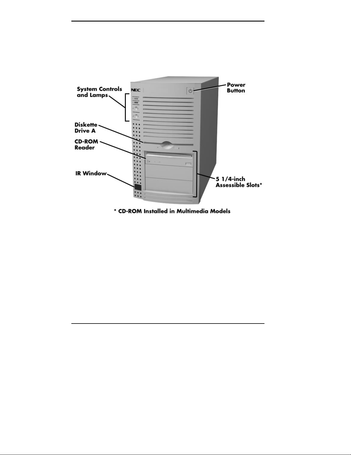
FRONT FEATURES
The following figures show the features on the front of the
system. A brief description of the features follows the
figures.
The following figure shows the lamps and controls called
out in the previous figure.
1-2 Introducing Your Computer
Front features
Page 16
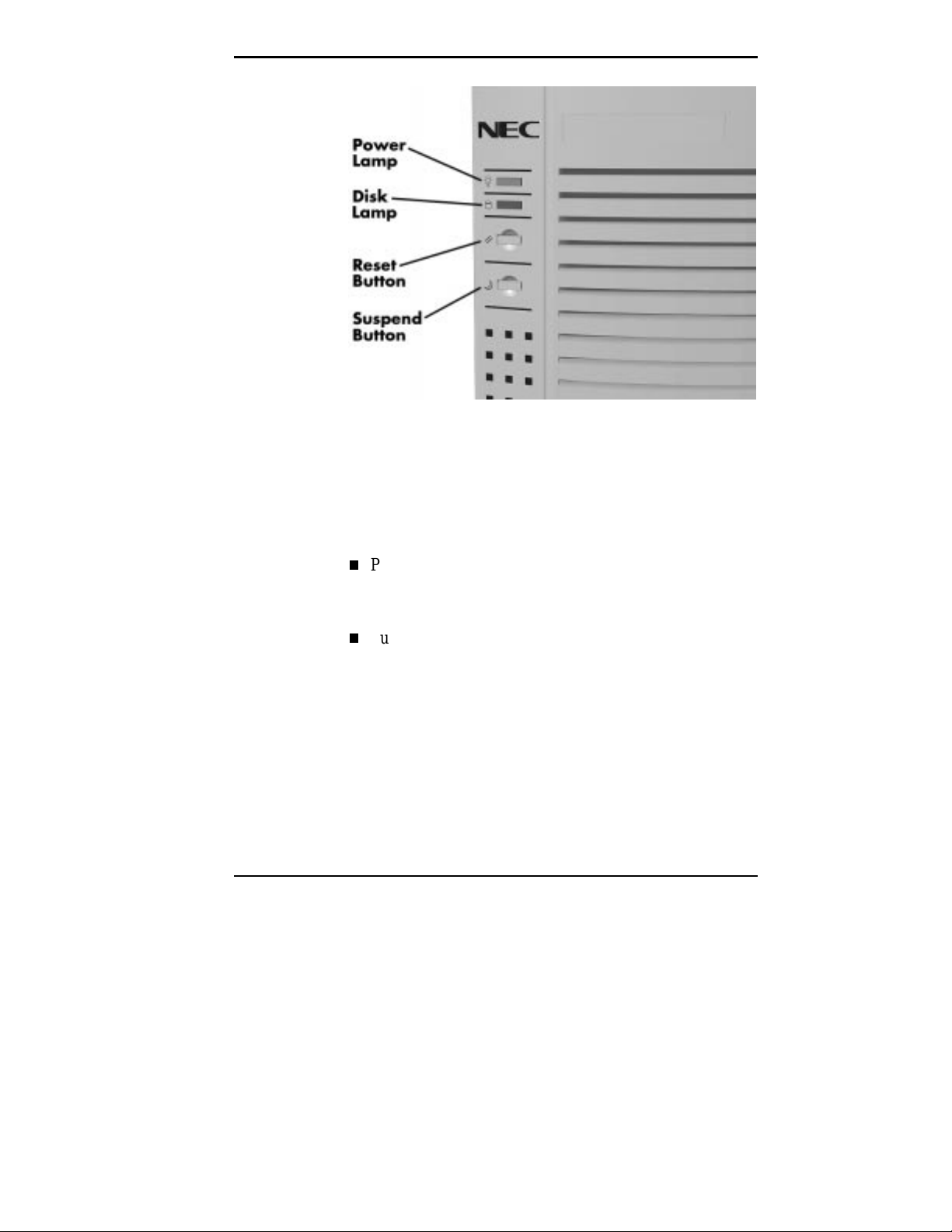
System Controls and Lamps
System controls let you select specific system operations.
Lamps let you know the status of system operation. Your
computer has the following controls and lamps:
System controls and lamps
Power button
Press this button to turn on system power. Press it again
to turn off the power.
Suspend button
If supported by the operating system, lets you initiate a
power-saving mode of operating your computer. Press
this button to suspend system operation when you plan
to be away from your computer for a short time. Press
any key or move your mouse to resume system operation
to where you stopped it.
A blinking system unit power lamp lets you know that
the system is in a power-saving mode.
Introducing Your Computer 1-3
Page 17
Reset button
The reset button lets you manually restart your system
when it does not respond to keyboard commands.
!
Resetti ng your system can resul t i n t he loss of dat a.
Press the reset button only when all other methods
of restarting your computer fails.
Power lamp
The power lamp indicates whether system power is on or
off.
A steady green lamp indicates that the power is on to all
system components.
Disk lamp
Indicates if your hard disk is doing anything. A green
lamp tells you that the hard disk is reading or writing
data.
CAUTION
Do not turn off the system, unless absolutely
necessary, while the di sk l amp is lit . To do so can
damage your hard disk or data.
IR Window
The IR (infrared) window is the system’s IR port. The
IR port supports two-way wireless communications. The
interface uses infrared as the transmission medium
instead of a traditional cable.
1-4 Introducing Your Computer
!
CAUTION
Page 18
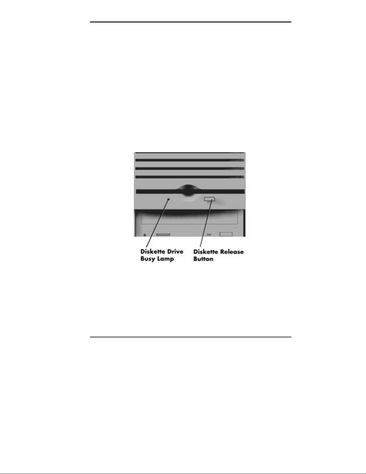
Diskette Drive A
Diskette drive A loads and starts programs from a diskette.
Diskette drive A is your primary “bootable” drive.
The IR port lets you transfer files to or from portable
devices such as laptops and personal digital assistance
(PDA) products using application software supporting
IrDA data transfer. You can order the Puma TranXit™
software (when it becomes available) for wireless data
transfer from a coupon included with your system.
With IrDA software, you can transfer data at speeds of
up to 115 kilobytes per second and at distances up to
3 feet from the IR window.
Diskette drive A features
Introducing Your Computer 1-5
Page 19

Your diskette drive has the following features:
To prev ent damage to y our di skette dr iv e and data,
do not turn off the system or remove a diskette
while the diskette drive busy lamp is lit.
CD-ROM Reader
An eight-speed CD-ROM reader is a standard feature in
multimedia models. The CD-ROM reader is assigned as
drive E.
Diskette drive busy lamp
Lights when your diskette drive is reading to or writing
from a diskette.
!
Diskette drive eject button
Press this button to remove a diskette from the diskette
drive.
CAUTION
Use the CD-ROM reader to load and start programs from a
compact disc (CD). You can also use the CD-ROM reader
to play your audio CDs. The CD-ROM reader is fully
compatible with Kodak Multisession Photo CDs and
standard audio CDs.
The CD-ROM reader operates at different speeds depending
on whether the CD you are using contains data or music.
This allows you to get your data faster and to see smoother
animation and video.
1-6 Introducing Your Computer
Page 20
NOTE
The CD-ROM reader in your system might
look different from the one shown here.
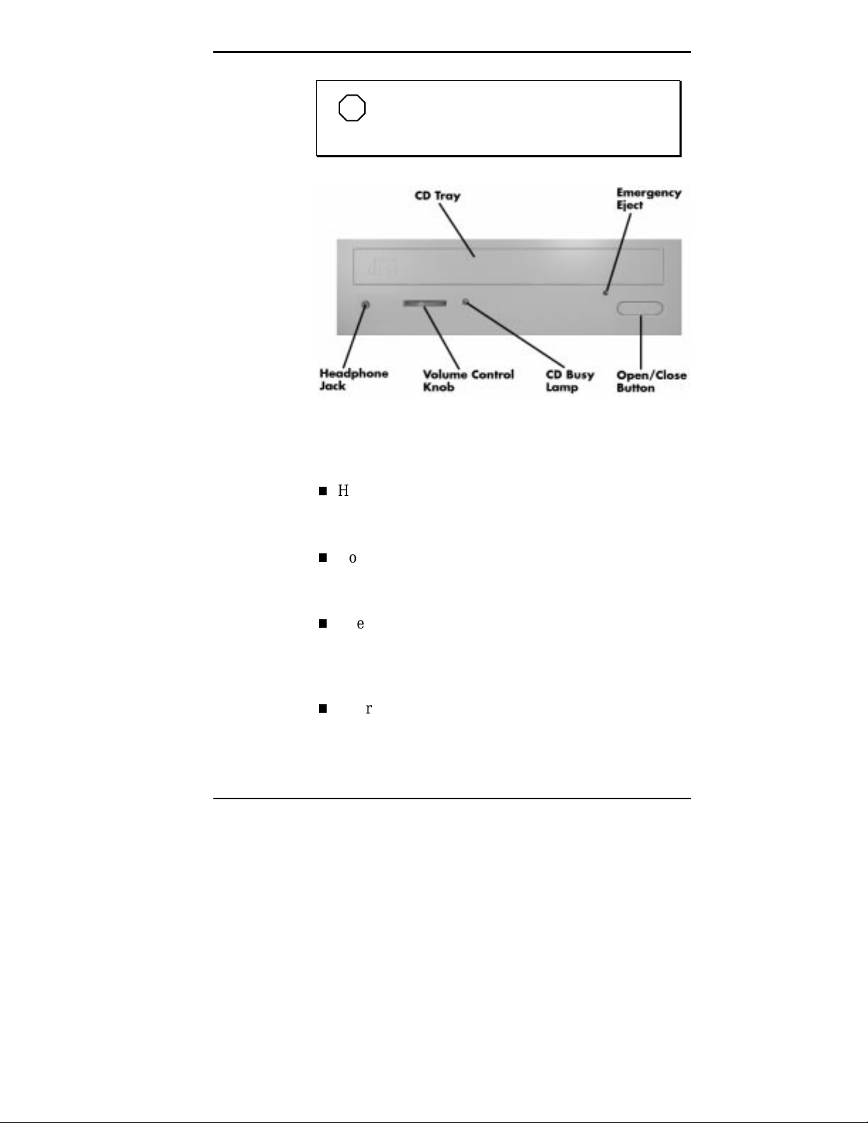
CD-ROM reader features
The CD-ROM reader has the following features:
Headphone jack
Allows the connection of an optional set of headphones
with a stereo mini-jack plug.
Volume control knob
Lets you adjust the volume of an optional set of
headphones.
Open/close button
Opens or closes the reader’s loading tray. Press this
button when the computer power is on to insert or
remove a CD into or out of the reader.
Emergency eject hole
Allows the manual ejection of a CD if the eject function
is disabled by software or if a power failure occurs.
Introducing Your Computer 1-7
Page 21
CD busy lamp
Lights when the reader is retrieving data, music, or
graphics/audio from a CD. Do not eject the CD or turn
off the system unit when the lamp is on.
CD tray
Provides a surface for loading a CD into the reader.
Press the open/close button to open or close the CD tray.
BACK FEATURES
On the back of your computer, you’ll find external
connectors, power supply features, and expansion board
slots. The following figures show these features.
1-8 Introducing Your Computer
Rear features
Page 22
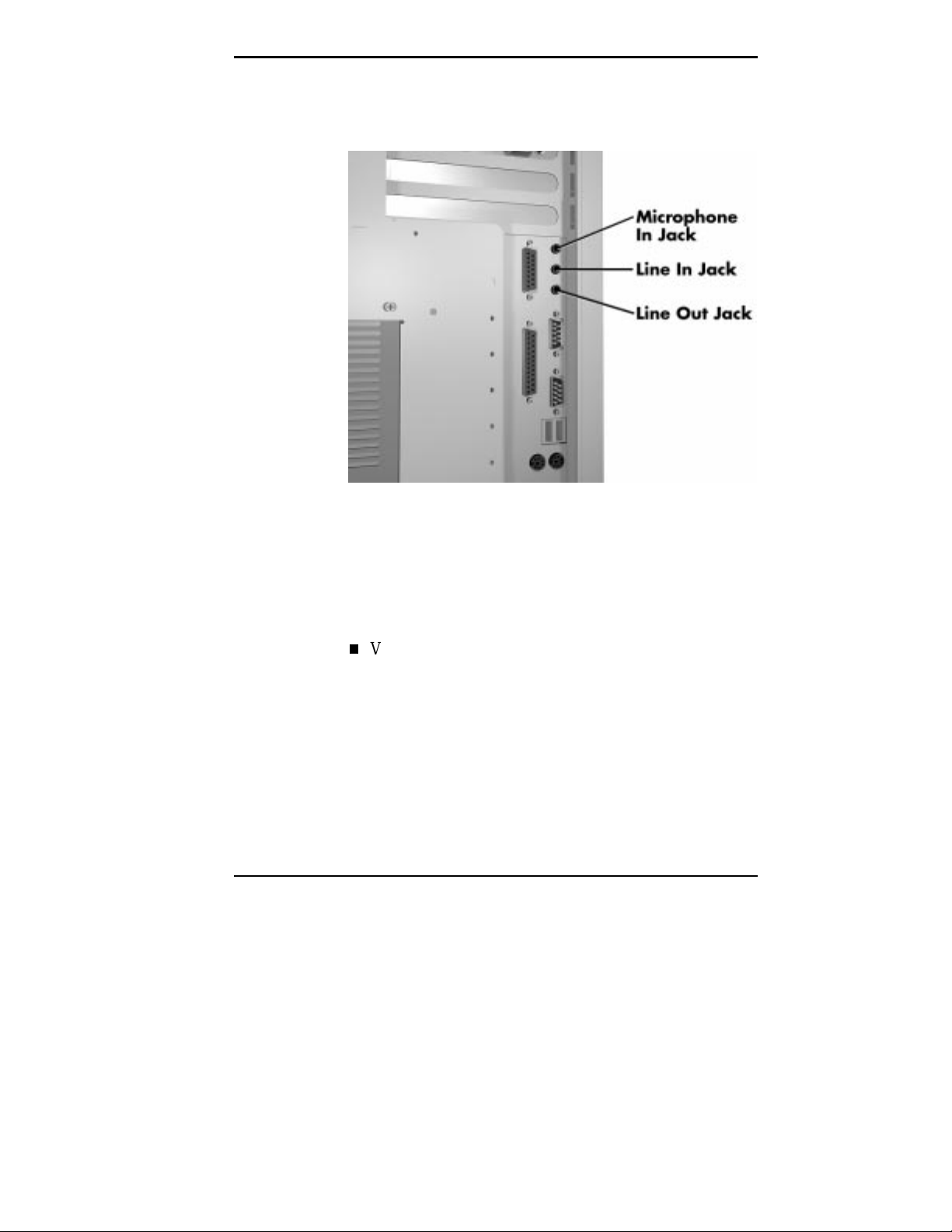
The following figure identifies the audio connectors
(multimedia systems only) called out in the previous figure.
Audio connectors
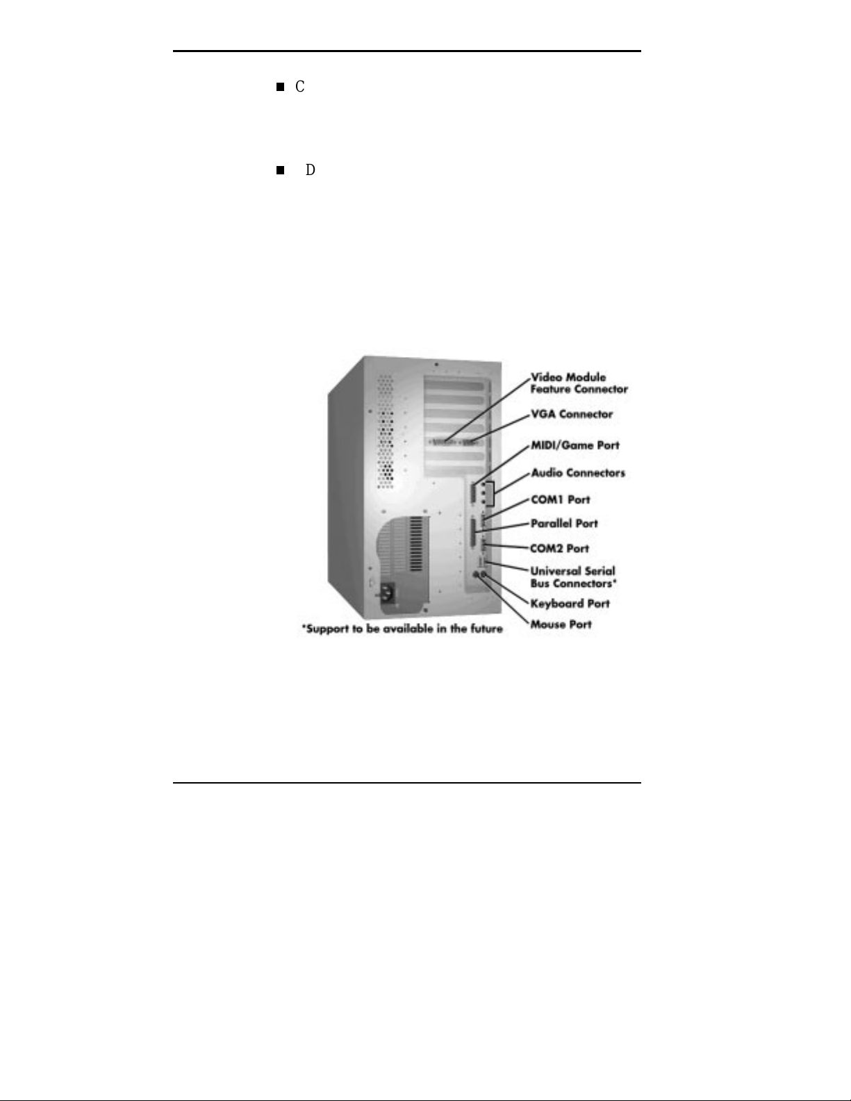
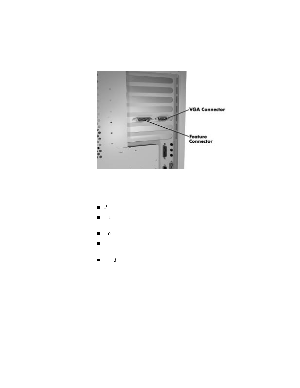
External Connectors
External connectors let you attach peripheral devices, such
as a monitor, keyboard, mouse, and printer to your system.
Your system has the following external connectors:
VGA monitor connector
Attach the signal cable from your monitor to this
connector. Supports an NEC MultiSync
other video graphics array (VGA)-compatible monitor
with a 15-pin connector.
®
monitor or
Introducing Your Computer 1-9
Page 23

Audio connectors
These connectors come integrated on multimedia models.
The connectors include microphone in, line in, and line
out jacks.
The microphone in jack lets you connect a
microphone for recording audio information in your
data system files, allows hands-free speakerphone
functions.
The line in jack lets you connect a stereo audio
device such as a stereo amplifier or a cassette or
minidisc player for playback or recording.
The line out jack allows you to connect an amplified
output device such as powered speakers, stereo tape
recorder, or an external amplifier for audio output.
Use this jack to connect the stereo speakers that
come with your system.
Printer Port
Use this port to connect a parallel printer with a 25-pin
connector to the system.
Serial ports
Attach a serial device with a 9-pin connector to each
serial port. Serial devices include a pointing device,
serial printer, or modem.
SCSI port
Wide SCSI allows connection of up to 15 SCSI devices.
Keyboard port
Attach the keyboard that comes with your computer to
this connector.
The keyboard port supports a personal system (PS)/2®compatible, 104-key keyboard with a 6-pin mini DIN
connector.
1-10 Introducing Your Computer
Page 24
Mouse port
Attach the mouse that comes with your computer to this
port. The mouse port supports a PS/2-compatible
mouse.
Universal Serial Bus (USB) ports
Connects USB devices soon to be released. With USB
ports, you can connect mice, joysticks, keyboards, and
telecommunication devices. The speed varies between 12
megabits per second (Mbps) for printers and 1.5 Mbps
for mice and keyboards. You can daisy chain up to 127
devices using USB ports.
Power Supply Features
The system power supply has the following features.
Power supply fan
Keep this area clear for proper ventilation. The power
supply fan cools system components and prevents them
from overheating.
Voltage selector switch
Sets the voltage for your system to 115 volts or
230 volts.
!
Set the switch correctl y f or the v olt age in your ar ea.
Most wall outlets in the United States and Canada
are 115 vol t s. Out let s in Eur ope, Austr ali a, and Asi a
(except Taiwan) are 230 volts. Taiwan uses 115-volt
outlets.
Power socket
Connect your power cable to this socket.
CAUTION
Introducing Your Computer 1-11
Page 25
Matrox Video Board
Installed in your system is a Matrox MGA Millennium
64-bit video board with true color, digital video and 3D
integrated into a single chip. The 3D graphics engine
renders your 3D applications in photo-realistic colors and
textures for you to manipulate.
The MGA Millennium video board offers the following
additional features.
Peripheral component interconnect (PCI) local bus
Window random access memory (WRAM) graphics
accelerator
2 or 4 MB of video WRAM
200 MHz (220 MHz for SCSI) DAC for flicker-free
refresh
Standard VGA monitor and video feature connectors
1-12 Introducing Your Computer
Matrox video board
Page 26
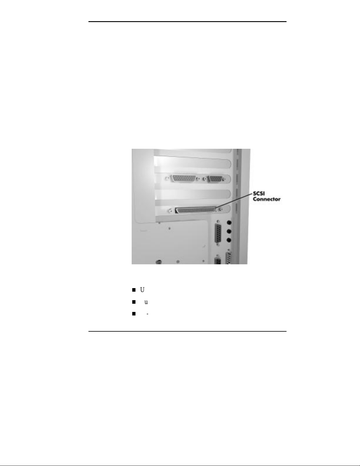
SCSI Adapter Board
Some configurations come with an Adaptec SCSI adapter
board installed in a PCI expansion slot. The SCSI adapter
board brings the highest performance SCSI I/O technology
to the PCI local-bus, transferring data up to 133
MB/second.
The BIOS-resident SCSISelect configuration utility
eliminates the need to handle jumpers or terminators while
adding peripherals. For further information on using the
SCSISelect utility, see “SCSISelect Utility” in Chapter 4.
All configuration and terminator settings are controlled
through the keyboard. The SCSI adapter board features the
following:
Utilizes PCI local bus
Bus master DMA interface protocol
32-bit bus width
SCSI Adapter Board
Introducing Your Computer 1-13
Page 27
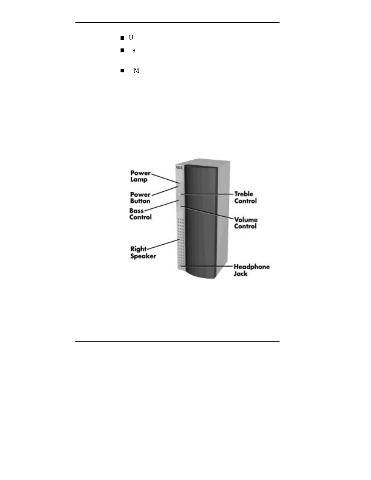
Speakers
Up to 133 MB/second data transfer rate
Fast and wide 20 MB/second SCSI synchronous data
rate
6 MB/second SCSI asynchronous data rate
Multimedia models come with a pair of high-quality 20
Watt stereo speakers that you can arrange to suit your work
environment.
An AC adapter comes with the system. Set up the speakers
with the AC adapter. The speakers connect to the line out
jack on the back of the system unit.
1-14 Introducing Your Computer
20 Watt Speaker
Page 28

Microphone
The speaker set features a power button, power lamp,
volume knob, treble and bass controls, and headphone jack.
Adjust the speaker volume by using the volume control on
the front of the right speaker.
The microphone allows you to record voice and sound into
your computer data files.
Microphone
Introducing Your Computer 1-15
Page 29

Using Your Computer
2
Now that you are familiar with your system, this chapter
provides the information you need to start using your
computer. Some of the information provided includes:
System operation
Productivity
Changing video drivers
System care.
SYSTEM OPERATION
In this section you will find information on starting up and
shutting down your system, setting the date and time, using
system and protection features.
Starting up
Press the power button to start up your system. The power
lamp lights green to indicate that the system is on.
When you are starting Windows NT™ 4.0 press
, you'll see several configuration messages display on
Del
the screen at startup.
These messages are part of your system's Power-On Self-
Test (POST). Your computer is checking your hardware for
any changes since the last startup. One beep indicates that
the system has successfully completed the power-on test.
Using Your Computer 2-1
Ctrl-Alt-
Page 30

If a problem occurs, a series of beeps may sound. If this
happens repeatedly after powering on, power off the system
and turn to Chapter 8, If You Have a Problem. This chapter
provides some helpful hints on obvious system problems.
Shutting Down
Follow these steps to shut down (power off) your computer.
1.
NOTE
You can bypass the POST memory test by
pressing the space bar.
NOTE
If the system displays a message i ndicating
that system sett ings have changed, run Setup (see
Chapter 4, NEC Drivers and Utilities).
Save your work. See the documentation that comes with
your application.
Exit the application program. If you are in Windows,
2.
select File. Select Logoff or Shutdown. Selecting
Shutdown gives you a choice of Shutdown or
Shutdown/Restart. Select Shutdown again.
Make sure that the hard disk and diskette drives are not
3.
in use. A lit hard disk lamp or diskette drive busy lamp
indicates that a drive is in use.
Turn off power to your monitor.
4.
Power off the system by pressing the system unit power
5.
button.
2-2 Using Your Computer
Page 31

Wait until a program is finished running before
powering off the system.
Unless absolutely necessary, never power off the
system when the system power lam p is blinking or
when the hard di sk lam p or disket te dri ve busy lam p
is lit. Inf ormati on on t he hard disk or diskette m ight
be lost or damaged.
Setting Date and Time
To set the system date and time within Windows, select the
Control Panel and double click on the Date/Time icon.
Set the time by entering the current hour, minutes and
seconds in hh:mm:ss, 24-hour format. For example, set
4:30 pm as
Set the date by entering the current day, month and year in
mm/dd/yy format. For example, set May 8, l996 as
05/08/96
.
16:30:00
!
CAUTION
.
NOTE
When setting the time and date, enter any
preceding zeros.
Using Your Computer 2-3
Page 32

Using System Features
The following sections explain how to use and maintain
your mouse, load and unload diskettes and CDs (if you have
a CD-ROM drive), and use your system’s audio features.
Using a Mouse
Use the mouse (shown in the following figure) to quickly
move around on the screen, to select menu items, and to
choose functions specific to your software.
Use the mouse to
Click
Clicking selects an object on your screen. To “click,”
point to the object and press and release the left mouse
button.
2-4 Using Your Computer
Mouse
Page 33

Double click
Some actions require a double click to execute them. To
“double click” an object, point to the object and press
and release the left mouse button twice.
Press
Pressing a mouse button holds an action until you
release a mouse button.
Drag
Dragging your mouse attaches your pointer to an object
on the screen and allows you to highlight text or move
an object. To drag an object, point to the object, press
the left mouse button, and move the mouse to the new
location.
Typical screen objects that you click or double click are
icons, buttons, and menu options.
NOTE
If your mouse pointer disappears, m ove your
mouse in wide circles to bring it back into the
screen.
Use a mouse pad for best results with your mouse. The
mouse pad provides traction for moving the mouse and
results in more sensitivity and control of movement. A
textured pad provides more traction than a smooth pad.
Keep the mouse pad clean.
Using Your Computer 2-5
Page 34

Using Diskettes
Follow these steps to insert a 3 1/2-inch diskette in the
standard diskette drive.
1.
2.
must f ormat it bef ore storing inf ormati on on it. See
your operating system documentation for
information about formatting a diskette.
Do not format your hard disk. Formatting the
hard disk will erase all preinstalled applications
Diskette Removal
To remove a diskette from the diskette drive, press the
release button on the 3 1/2-inch diskette drive.
Holding the diskette at its top edge, insert it, label side
up, into the diskette drive.
Insert the diskette all the way into the drive until you
hear a click.
NOTE
If your diskett e di d not come form atted, you
.
2-6 Using Your Computer
Page 35

Removing a diskette
!
Do not remove a diskette from the diskette drive
when the diskette drive lamp is lit. To do so can
damage both the data on the diskette and the drive.
CAUTION
Do not turn off the system power while the disket te
is being accessed.
Do not reset the system (except as a last resort)
when the diskette drive is in use.
Using Your Computer 2-7
Page 36

Handling Compact Discs
To protect your CDs from damage, use the following
guidelines when you handle them.
Always pick up the disc by its edges.
Avoid touching the side of the disc that has no printing
or writing on it. This is the data side of the disc.
Handling a CD
Do not write on or apply labels to either side of the disc.
Keep the disc away from direct sunlight or high
temperatures.
Clean fingerprints or dust from the disc by wiping it
with a soft cloth. Gently, brush the cloth from the center
of the disc toward the edge.
2-8 Using Your Computer
Page 37

Cleaning a CD
!
Av oid using benzene, pai nt thinner, recor d cleaner,
static repellent, or any other chemical on the disc.
Chemicals and cleaners can damage the disc.
CAUTION
Loading a CD
To insert a CD into the CD-ROM reader, follow these
steps:
1.
Press the open/close button. A CD tray will emerge from
the reader door.
2.
Remove the CD from its protective case. Hold the CD
by its center hole and outer edges to avoid touching its
surface.
3.
Place the CD, printed side up, into the circular area of
the tray.
4.
Press the open/close button again. The reader
automatically pulls in the tray.
Using Your Computer 2-9
Page 38

Removing a CD
To remove a CD, simply press the open/close button and
remove the CD when the tray slides out. Press the
open/close button again to close the reader door.
Using Your Systems Audio Functions
Multimedia systems come with all the audio functions and
components you need to produce output close to concert
hall performance.
The integrated audio components in multimedia systems
provide support for the four major sound standards
including Adlib, Sound Blaster™ Pro 2.0, Windows Sound
System™, and MPU-401 to provide all the functionality
required for your multimedia applications.
Suspend Power
You can manually initiate a Suspend power-saving mode
instantly by pressing the suspend button (dependent on
operating system support) on the front of your unit.
Pressing the suspend button is a convenient way of
conserving energy when you are going to be away from
your system for a short period of time.
The suspend button i s below the reset button. Tak e
care to av oid pressing the reset but ton by accident .
Accidently pressing the reset but ton can result i n the
loss of data.
2-10 Using Your Computer
!
CAUTION
Page 39

Suspend mode provides the greatest power savings by
putting the system in a maximum power shutdown. When
the system goes into Suspend mode, it saves data and
system status and then shuts off power to all possible
components. Suspend mode lets you save power without
first saving your work.
A blinking power lamp indicates your system is in a powersaving mode. Press a key or move your mouse to resume
system operation to where you left off.
Protection Features
Your system’s security features provide protection against
unauthorized access to your system and data. This
protection includes a user and administrator password.
When you start up your system for the first time, you are
asked to enter a system password. The following section
explains the password procedure.
Setting a Password
Use the following procedure to set a password.
Turn on or reboot your system. Setup displays the
1.
following message:
Press <F1> to enter SETUP
Press F1. Setup's Main Menu window appears.
2.
Using your arrow keys, select Security from the menu
3.
bar. The Security menu appears.
Select “Set Administrator Password.” with the arrow
4.
keys and press
. (Once you enable the
Enter
Administrator Password, the “Set User Password” can
be enabled.)
Using Your Computer 2-11
Page 40

NOTE
requires that a password be entered before ent ering
the Setup Utility.
Enabling t he Admini strator Password feat ure
Setup displays a dialog box with the following
prompts:
Enter new password: [ ]
Confirm new password: [ ]
Type your password (passwords are not case sensitive)
5.
and press
again.
Enter
Use the arrow keys to select Exit.
6.
. Reenter your password and press
Enter
Select Exit Saving Changes. Press
7.
At the prompt, to confirm exiting setup, press
8.
Your password takes affect the next time you power on
the system. You must enter a password the next time
you power on.
Using a Password
After you set your password in Setup and reboot the
system, a password prompt appears each time you power on
the system.
To use your password, type the password at the password
prompt and press
Enter
.
Enter
.
Enter
.
2-12 Using Your Computer
Page 41

NOTE
For security, characters you enter do not
appear on your screen. Enter your password
carefully.
If you enter the password incorrectly, your system does not
boot. You have three chances to enter the correct password.
After the third unsuccessful attempt, you must reboot your
system and try again.
NOTE
If you f orget your password, you must clear
the password by setting a jumper on the system
board (see “Clearing Your Password” in Chapter 6.
Once you clear the password, you can boot your
system and set a new password in Setup.
Dual password security provides two levels of password
security. An administrator password allows access to
the system’s Setup utility for system configuration. A
user password allows system boot-up only after the
entry of a password.
Using Your Computer 2-13
Page 42

PRODUCTIVITY
The following sections explain how to use your system to
maximize your productivity effectively.
Saving Your Work
Save your work often! The time you take to periodically
save your data file as you work can save you time in the
end! Prevent losing a whole day's work or more when the
unexpected happens, such as losing power due to a power
outage.
Some applications provide automatic save options for
specified intervals of time as you work. For example, you
might want to save your work every 10 minutes. This
reduces the amount of lost information should you lose your
power or experience some other problem.
In Windows programs, you can select a save option from
the File menu. If you are creating a new file, you'll need to
specify a name for your file and a location to store it (drive
and directory).
Always save your work before you exit an application. See
the application's documentation for available save options.
Backing Up Your Work
Back up your work on a regular basis! Backup procedures
are important for the efficient and effective use of your
computer. Protect your program and data files with regular
backup procedures.
Make backup copies of your program and data files that are
on diskette and on the hard disk.
The standard practice for diskette backup is to copy each
diskette, store the original in a safe place, and use the copy
as your working diskette. See your operating system
documentation for information about copying diskettes.
2-14 Using Your Computer
Page 43

Printing a Document
Before you can print out a document, you must
connect a printer to your computer
set up the printer.
If you have not connected a printer, see “Connecting a
Parallel Printer,” in Chapter 5.
If you did not choose a printer when you initially set up
your computer, you'll need to do that before you can print
(see your Windows documentation). If you are using a nonWindows program, you'll need to set up a printer driver for
that program. See your printer documentation for printer
setup information.
Once your program is set up to work with your printer,
printing a file within a Windows application is easy:
Turn on your printer power.
1.
Be sure you have paper in your printer. See your printer
2.
documentation to load paper.
Check that the printer is “online” or “selected.” See your
3.
printer documentation for information about choosing
the online mode.
Select Print from the File menu of your Windows
4.
application. A Print dialog box appears.
Select how many print copies you want and the range of
5.
pages. To print one copy of all the pages, simply click
OK.
Using Your Computer 2-15
Page 44

CHANGING VIDEO DRIVERS
The following procedure provides instructions on how to
change your video drivers.
From the Main program window, double click the MGA
1.
Control Panel/Display icon.
Click on List All Modes. You get a list of all the modes
2.
available for your video board.
To modify colors or your desktop, select Color Palette
3.
and Desktop Area to change your selections.
.For the best display, be sure you select the monitor type.
The driver is set at 60 Hz refresh rate. If your monitor is
capable of higher refresh rates, select the Control
Panel/MGA Monitor icon to change the setting to your
monitor type or to an equivalent monitor.
NOTE
If your monitor is flickering or you change
your moni tor, check that the Moni t or ty pe param eter
is set correctly for your monitor.
SYSTEM CARE
Your system is a durable, dependable computer built for
lots of use. With protective measures and proper care, you
can prevent problems and promote the successful operation
and long life span of your computer.
2-16 Using Your Computer
Page 45

Protecting Your System from Damage
There are several ways that you can protect your system
from possible damage. NEC strongly recommends the
following protective measures:
Connect a surge suppressor between your computer and
a grounded wall outlet. A surge suppressor protects your
system from sudden transient increases and decreases in
electrical power.
Be sure to connect all peripherals, such as your monitor
and printer, to the surge protector. The surge protector
should be the only device that you plug into the wall
outlet.
Avoid repeated power-on cycles as this subjects the
system components to temperature variations and stress.
Disconnect your system from telephone and power lines
when an electrical storm threatens. If you have a
fax/modem, lightning can travel in on the phone line and
damage both the fax/modem and the system unit.
Lightening can also travel in on power lines and damage
your monitor and system unit.
Be sure that system power is off before you connect or
disconnect a cable. Never make cable changes when the
system power is on. To do so could damage your system
and its peripherals.
Use Setup options to protect against viruses (see
“Security Menu” in Chapter 4). Use appropriate virus
detection software regularly to protect your system from
computer viruses.
If you plan to use software programs other than NEC
supplied software, NEC strongly recommends that you
take the necessary steps, such as virus checks, to protect
your system.
Using Your Computer 2-17
Page 46

Place your computer away from direct sunlight and
extreme hot and cold temperatures.
The recommended operating environment is from 50°F
to 95°F (10°C to 35°C).
The recommended non-operating environment (shipping
or storage) is from 14°F to 158°F (10°C to 70°C).
After turning off power, wait about five seconds for the
hard disk to spin down before you power on again.
Be sure that nothing is placed on top of your system
power cables.
Prevent dust from entering your system by covering it
when it is not in use.
Keeping Your System in Good Condition
Maintain the condition of your system by periodically
following the general procedures listed next.
For safety, power off and unplug your system,
monitor, and any external options before cleaning
them.
2-18 Using Your Computer
!
WARNING
Page 47

Clean the outside of the computer with a soft clean cloth.
You can remove stubborn stains with a cloth slightly
dampened with a mild detergent. Never use a strong
cleaner or solvent on any part of the system.
Keep food and liquids away from your computer.
Periodically clean the keyboard with a vacuum cleaner
brush attachment. Do not use any liquid cleaners on the
keyboard as they can damage the keyboard.
If an object, such as a paper clip, falls into the keyboard,
turn the keyboard over and gently shake it.
Clean the monitor screen with a glass cleaner and wipe it
with a clean, lint-free cloth. Or use wet/dry cleaning
pads manufactured for monitor screens.
Cleaning Your Mouse
.Under normal conditions, your mouse has a self-cleaning
mechanism that prevents a buildup of dust or lint around the
mouse ball and tracking mechanism. Periodically, however,
you might need to wipe the mouse ball clean.
Using Your Computer 2-19
Page 48

Use these steps to clean your mouse:
Power off your computer and any peripherals attached
1.
to it.
Invert the mouse. Locate the mouse ball cover.
2.
Mouse ball cover
Rotate the ball cover clockwise and remove the cover.
3.
Turn the mouse over so that the cover and ball fall into
4.
your palm.
Gently push the ball out of the large opening in the side
5.
of the ball cover.
Clean the mouse as follows.
6.
2-20 Using Your Computer
Use tap water, or tap water and a mild detergent to
clean the mouse ball.
Use a clean, lint-free cloth to dry the ball.
Blow into the mouse socket to remove remaining dust
or lint.
Page 49

Gently put the ball back into the mouse ball cover.
7.
Fit the ball cover back into the mouse and turn the cover
8.
counterclockwise until it locks in place.
Moving or Shipping Your System
Use these steps to prepare your system for moving or
shipping:.
Back up your hard disk files onto diskettes or tape
1.
cartridges.
Be sure to take precautions for storing and transporting
diskettes or cartridges so that they are not exposed to
magnetic fields or electrical impulses.
Remove any diskette from the diskette drive. If you have
2.
a CD in the CD-ROM reader, remove the CD.
Turn off the system unit and any external options
3.
connected to it.
Unplug the system unit power cable from the wall outlet
4.
or surge suppressor, then from the unit.
Unplug any external options from the wall outlets or
5.
surge suppressor, then disconnect them from the system
unit.
Pack the system components in the original shipping
6.
materials and cartons. If these are not available, be sure
to use adequate packing materials to protect the
components.
To set up your system, follow the steps on the PowerMate
Pro2200/2180 Quick Setup Sheet that comes with your
computer.
Using Your Computer 2-21
Page 50
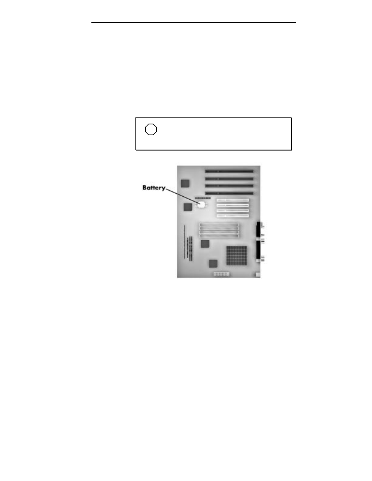
Battery Replacement
All system boards use a battery to maintain system
configuration. Some system boards use a 3-volt lithium
battery. If your system uses this type of battery (see the
following figure) and it fails to maintain system
configuration information, replace it with an identically
rated battery from the same manufacturer.
Removing the battery from the system board
causes the computer to lose system configuration
information. If you can, run the Setup Utility and
print out or write down your system configuration
settings. Then you can restore your system to its
current settings.
!
CAUTION
The batt ery can explode i f it is incorrect ly replac ed
or impr operly discarded. Use only the same batt ery
or an equivalent type recommended by the
manufacturer when replacing the battery.
Lithium acts as a catalyst when exposed to water
and causes spontaneous combustion on contact.
Discard used batteries according to the
manufacturer’s instructions.
2-22 Using Your Computer
!
WARNING
Page 51
If you need to replace the battery, follow these steps:
Turn off and unplug the computer and any external
1.
components connected to it.
Remove the system unit cover. Observe all safety
2.
precautions when removing the cover.
Locate the battery socket on the system board. You may
3.
have to remove any expansion boards in the way.
NOTE
This procedure i s for system boards using the
3-volt lithium battery shown in the following figure.
Locating the battery socket on the system board
Using Your Computer 2-23
Page 52

Carefully lift the battery clip until there is enough space
4.
to slide the battery out of the socket.
!
To maintain a tight battery contact with the socket,
do not over-bend the battery clip.
CAUTION
Removing the battery
5.
Remove the battery and discard in accordance with the
manufacturer’s instructions.
6.
Carefully lift the clip on the battery socket.
7.
With the positive (+) side facing up, slide the new
battery into the socket.
8.
Replace any removed expansion boards.
2-24 Using Your Computer
Page 53

Replace the system unit cover.
9.
Connect external peripherals and power cables
10.
Run the Setup Utility to reconfigure your system
parameters.
Using Your Computer 2-25
Page 54

Understanding System
3
Features
The PowerMate Pro2200 is a 200-MHz Pentium Pro-based
system. The PowerMate Pro2180 is a 180 MHz Pentium
Pro-based system. The Pro2200 system comes standard
with an Intel Pentium Pro™ 200 MHz processor and the
Pro2180 comes standard with an Intel Pentium Pro 180
MHz processor. Both systems come with a 3 1/2-inch
diskette drive, 2.1 GB IDE (2.0 GB SCSI configuration)
hard disk, 16-megabyte (MB) random access memory
(RAM), and a 2 MB Matrox video board.
Multimedia configurations come with the above features
and an eight-speed CD-ROM reader, 20 watt (W) external
speakers and microphone. The SCSI multimedia
configuration comes with 32 MB of RAM memory, a 2.0
GB SCSI hard disk, an Adaptec SCSI controller board, and
a 4 MB Matrox video board.
All of the systems ship with the following software.
Microsoft® Windows NT™ 4.0 and Healthy
Environment Help file installed
Matrox Windows NT 4.0 video drivers installed
Crystal audio drivers/business audio mixer and input
installed (multimedia configurations only)
Understanding System Features 3-1
Page 55

Microsoft Internet Explorer for Windows NT
installed
McAfee VirusScan for Windows NT (1 diskette)
LanDesk Client Manager installed
Microsoft Windows NT Bus Master IDE driver installed
NEC 8X CD-ROM drivers installed (multimedia
configurations only)
Adaptec 7800 Manager Set drivers installed (SCSI
configuration only)
You can order Puma TranXit for Windows NT from a
coupon (if diskettes are not included with your system).
SYSTEM CHASSIS
The chassis provides an enclosure for the system board,
power supply, seven PCI/ISA expansion slots and six
storage device slots. The expansion slots include three 8/16-bit ISA slots, one shared PCI/ISA slot, and three 32-bit
PCI slot.
The six storage device slots accommodate up to four
accessible devices and two internal hard disk drive devices.
The accessible devices include the standard one-inch high 3
1/2-inch 1.44-MB diskette drive and up to three 1.6-inch
high 5 1/4-inch storage devices. The internal device slots
support up to two 1-inch high 3 1/2-inch hard disks.
The following figure shows the front panel features and the
locations of the accessible storage devices in a system.
3-2 Understanding System Features
Page 56

SYSTEM BOARD COMPONENTS
Your PowerMate Pro2200/2180 system board has the
following components.
System chassis features
Processor
Processing for your system is provided by the 200-MHz
Intel® Pentium™ Pro or 180-MHz Intel Pentium Pro
central processing unit (CPU). The Pentium Pro integrates
the 256 KB secondary cache and cache controller to free up
space on the system board and further improve system
performance. In addition, the integrated math coprocessor
significantly increases the speed of floating point
operations. The system comes equipped with the latest 387pin zero-insertion-force (ZIF) socket for easy processor
upgrades with future Pentium Pro OverDrive™ processors.
Understanding System Features 3-3
Page 57

System Memory
The system comes with 16 MB (32 MB SCSI
configuration) of system memory. Four sockets on the
system board support up to 256 MB of high-speed memory
using industry-standard tin-plated single in-line memory
modules (SIMM).
fast page mode (FPM) SIMMs into the SIMM
sockets.
To optimize the 64-bit memory path, install memory in
matching pairs. The system supports the following 72-pin
SIMM sticks:
NOTE
You may install AVL approv ed, 60- ns, pari ty,
1-MB by 32- or 36-bit SIMM (4-MB stick)
2-MB by 32- or 36-bit SIMM (8-MB stick)
4-MB by 32- or 36-bit SIMM (16-MB stick)
8-MB by 32- or 36-bit SIMM (32-MB stick)
16-MB by 32- or 36-bit SIMM (64-MB stick)
Interrupt Controller
The interrupt controller operates as an interrupt manager
for the entire system environment. The controller accepts
requests from peripherals, issues interrupt requests to the
processor, resolves interrupt priorities, and provides vectors
for the processor to determine which interrupt routine to
execute. The interrupt controller has priority assignment
modes that can be reconfigured at any time during system
operations.
3-4 Understanding System Features
Page 58

The interrupt levels are described in the following table.
Interrupt-level assignments 0 through 15 are in order of
decreasing priority. See Chapter 4, NEC Drivers and
Utilities, for information on changing the interrupts using
Setup.
Interrupt Level Assignments
Interrupt Priority Interrupt Device
NMI I/O channel check
IRQ00 Reserved, Interval Timer
IRQ01 Reserved, Keyboard buffer full
IRQ02 Reserved, Cascade interrupt from slave
IRQ03 Serial Port 2
IRQ04 Serial Port 1
IRQ05 User (audio on multimedia configurations)
IRQ06 Diskette Drive Controller
IRQ07 Parallel Port 1
IRQ08 Real-time clock
IRQ09 User (audio on multimedia
configurations)
IRQ10* User (SCSI board for SCSI configurations)
IRQ11* Video Board
IRQ12 On-board mouse port (available if no PS/2
mouse)
IRQ13 Reserved, Math Coprocessor
IRQ14 Primary IDE
IRQ15 Secondary IDE if present, or else user available
*These slots are selected and used by the installed expansion boards.
Understanding System Features 3-5
Page 59

PCI Local Bus
The 32-bit industry-standard PCI bus is a highly-integrated
input/output (I/O) interface that offers the highest
performance local bus available for the Pentium-based
processor. The PCI bus supports burst modes that send
large chunks of data across the bus, allowing fast displays
of high-resolution images.
The high-bandwidth PCI local bus eliminates data
bottlenecks found in traditional systems, maintains
maximum performance at high clock speeds, and provides a
clear upgrade path to future technologies.
The PCI bus contains two embedded PCI devices, the PCI
local bus IDE interface and the PCI video/graphics
controller.
Flash ROM
NEC’s Flash ROM allows fast, economical BIOS
upgrades. NEC Flash ROMs are reprogrammable system
and video EPROMs.
With NEC’s Flash ROM, a ROM BIOS change:
is fast and easily done using a Flash utility
eliminates the expensive replacement of ROM BIOS
chips, and reduces system maintenance costs
reduces inadvertent system board damage that can take
place when replacing ROMs
facilitates adopting new technology while maintaining
corporate standards
gives network administrators company-wide control of
BIOS revisions.
Information on how to use the Flash utility is provided in
Chapter 4, NEC Drivers and Utilities.
3-6 Understanding System Features
Page 60

Graphics Features
The system features a PCI local bus motion video playback
controller and graphics accelerator.
Motion Video Controller
The motion video controller is supported on 16 and 32 MB
multimedia configurations. The video controller integrates a
Windows graphical user interface (GUI) engine and motion
video playback hardware.
MPEG is a compression/decompression standard developed
by a professional video group called the Motion Picture
Experts Group. MPEG produces full-screen, 30-framesper-second (fps), broadcast-quality digital video. This
basically means viewing movies on your computer. Support
includes:
MPEG-1
Video for Windows.
Graphics Accelerator
The graphics accelerator is specifically designed for
graphics-intensive operations, text and color pixel
amplification, and scrolling. The graphics accelerator
provides 64-bit, ultra-high performance for demanding True
Color, High Color, and pseudocolor GUI and computeraided design (CAD) applications.
The accelerator minimizes bus traffic by off-loading the
tasks normally performed by the processor. The dedicated
bit-block transfer (BitBLT) engine maximizes performance
by speeding the movement of large blocks of image data in
video memory.
Understanding System Features 3-7
Page 61

Video Support
Your system comes in two configurations of standard video.
The nonmultimedia and multimedia configurations have a
2 MB board installed that is upgradeable to 4 MB with the
2 MB upgrade module. The SCSI multimedia configuration
has a 4 MB board installed that is upgradeable to 8 MB
with the 4 MB upgrade module. The video hardware system
supports the following resolutions, colors, and refresh rates:
1600 by 1200 pixels, 256 colors, 60-78 Hz
1280 by 1024 pixels, 256 colors, 60-110 Hz
1024 by 768 pixels, 256/65K colors, 60-120 Hz
640 by 480 pixels, 256/65K/16.7M colors, 60-200 Hz.
With 4 MB of video WRAM, the system supports the
following additional resolutions, colors, and refresh rates:
1600 by 1200 pixels, 256/65K colors, 60-78 Hz
1280 by 1024 pixels, 256/65K/16.7M colors, 60-110
Hz
1024 by 768 pixels, 256/65K/16.7M colors, 60-120 Hz.
640 by 480 pixels, 256/65K/16.7M colors, 60-200 Hz.
For 8 MB of video WRAM, the system supports the
following resolutions, colors and refresh rates.
1600 by 1200 pixels, 256/65K/16.7M colors, 60-78 Hz
1280 by 1024 pixels, 256/65K/16.7M colors, 60-110
Hz
1024 by 768 pixels, 256/65K/16.7M colors, 60-120 Hz.
640 by 480 pixels, 256/65K/16.7M colors, 60-200 Hz.
3-8 Understanding System Features
Page 62

Feature Connector
In addition to the standard VGA connector, the system
provides a VESA-compliant feature connector on the video
board.
High-Speed Communication Ports
Your system features an enhanced parallel port and
buffered high-speed serial port.
The enhanced parallel port supports Enhanced Capabilities
Port (ECP) and Enhanced Parallel Port (EPP) modes for
devices that require ECP or EPP protocols. These protocols
allow high-speed bidirectional transfer over a parallel port
and increase parallel port functionality by supporting more
devices.
The buffered high-speed serial port supports transfer rates
up to 19.2 kilobytes (KB) per second. These ports allow the
installation of high-speed serial devices for faster data
transfer rates.
The combination of the enhanced parallel port and buffered
serial port ensure optimum performance for future
peripheral devices and operating systems.
Dual IDE Ports
The system board in your system provides two internal IDE
ports:
Each port supports two devices for a total of four IDE
devices. Your computer allows the connection of an IDE
CD-ROM reader for system configuration flexibility
without the addition of a controller.
a primary IDE port
a secondary IDE port.
Understanding System Features 3-9
Page 63

USB Port
SCSI Port
Both the primary and secondary IDE ports feature an
enhanced IDE interface which supports up to 10 MB per
second 32-bit wide data transfers on the high-performance
PCI local bus.
The Universal Serial Bus (USB) port allows you to add new
serial devices without opening up the system, simply plug
them into the port. The USB determines system resources
for each peripheral and assigns them without user
intervention. Up to 127 devices can be daisy chained to a
single PC. .
The small computer system interface (SCSI) board installed
in SCSI configurations provide the highest performance
SCSI I/O technology to the fast PCI local-bus. The SCSI
port connects the hard disk in SCSI configurations and is
compatible with all SCSI-2 and SCSI-3 peripherals. The
BIOS-resident SCSISelect configuration utility eliminates
the need to set jumpers or terminators when adding
peripherals. Settings are controlled through the keyboard.
See Chapter 4, NEC Drivers and Utilities, for information
on using SCSISelect.
ZIF Socket
Your computer comes with the latest 387-pin ZIF socket for
upgradeability all the way to the next generation of Pentium
Pro OverDrive™ processors.
Sound System
The sound system in multimedia models provides
compatibility with Sound Blaster Pro™, Sound Blaster™
2.0, Ad Lib™, MPU-401, and Microsoft® Windows Sound
System™ for PC sound applications.
3-10 Understanding System Features
Page 64

For detailed sound specifications, see the “System
Specifications” later in this chapter.
Plug and Play Support
Your computer comes with a Plug and Play BIOS which
supports Plug and Play technology. Plug and Play
eliminates complicated setup procedures for installing Plug
and Play expansion boards.
With Plug and Play technology, you add a Plug and Play
expansion board simply by powering off the system,
installing the board, and powering on the system. There are
no jumpers to set and no system resource conflicts to
resolve. Plug and Play automatically configures the board
for your system.
Your system also supports non-Plug and Play boards.
Power Saving Feature
A suspend button lets you quickly put the system into a full
power reduction mode of operation. This is a convenient
way to save power when you need to be away from your
computer for a short period of time. Press a key or move the
mouse and your system quickly returns to full power and to
where you left off.
Understanding System Features 3-11
Page 65

NEC Drivers and
4
THE SETUP UTILITY
Utilities
This chapter provides information on the NEC utilities and
drivers that ship with your system. The following topics are
covered in this chapter.
Setup Utility
Flash Utility
SCSISelect Utility
Video Drivers
The Setup utility program allows you to enter system
configuration information and control special features of the
system.
NOTE
correct system parameters for your configuration.
Unless you add optional har dware, you do not need
to run Setup to oper ate your system . However , you
might wish to run the Setup utility to set features
that customize your system, such as security
features.
Your system ships from the factory with the
NEC Drivers and Utilities 4-1
Page 66

System configuration information is stored in nonvolatile
memory. A nonvolatile memory device retains its data when
system power is turned off. Nonvolatile memory in your
system is a complementary metal-oxide semiconductor
(CMOS) chip backed up by a battery on the system board.
The battery supplies continuous power to CMOS memory
and maintains configuration information when system
power is off (see “Battery Replacement” in Chapter 2).
NOTE
down your current Setup parameters and store the
information in a safe place. This lets you restore
your system to the current parameters if you ever
need to replace the battery.
When to Use Setup
The Setup utility lets you view and set system parameters.
Use the Setup utility program:
NEC recommends that you print out or write
to set the time and date.
to update or check system parameters when you add or
remove expansion options.
to change or set power management features.
to correct a hardware discrepancy when the Power-On
Self-Test (POST) displays an error message and
prompts you to run Setup.
4-2 NEC Drivers and Utilities
Page 67

to check the installation of optional memory by
comparing the amount of memory installed with the
amount of memory displayed by Setup.
to change certain system operating parameters, such as
boot device sequence and keyboard parameters.
to configure system connections for peripherals such as
your diskette drive, hard disks, and devices connected to
the printer port and serial ports.
to customize your system with security features such as
passwords, diskette drive restriction, virus check
reminder and system backup reminder.
to set system parameters in the event that you need to
replace the complimentary metal oxide semiconductor
(CMOS) battery.
How to Start Setup
To start the Setup utility, follow these steps:
Turn on or reboot the system.
1.
2.
Press
after POST, but before the system boots up, to
F1
start the memory test.
There are about five seconds to press
before system
F1
boot continues.
Setup’s Main Menu appears and looks similar to the
3.
following screen.
NEC Drivers and Utilities 4-3
Page 68

Main Advanced Security Exit
System Date June 26 1996 F1 Help
System Time 08:12:20 ESC Exit
Enter Select
Floppy Options Press Enter
Primary IDE Master ST32140A
Primary IDE Slave Not Installed
Secondary IDE Master NEC
Secondary IDE Slave None
Language English (US) F5 Setup Defaults
Boot Options Press Enter F6 Previous Defaults
F10 Save & Exit
Video Mode EGA/VGA
Mouse Installed
Base Memory 640
Extended Memory 15360
BIOS Version XX.XX
Previous Item
↑
Next Item
↓
Select Menu
←→
How to Use Setup
Use the keys shown on the right of the Setup menu to make
your selections or exit the current menu. The following
table describes the navigation keys and their alternates.
Main Menu
Key
F1 Provides help for the parameter field
Esc Exits the menu.
Enter Executes Command or Selects
↓ or ↑ arrow keys
4-4 NEC Drivers and Utilities
Navigation Keys
Function
being displayed.
submenu.
Moves cursor up and down.
Page 69

Navigation Keys
Key Function
MAIN MENU
← or → arrow
keys
F5 Loads the Default Configuration values
F6 Selects the Previous Value for the field.
F10 Loads the Previous Configuration
Selects next menu.
for this menu.
values for this menu.
To display a submenu, use the arrow keys to move the
cursor to the submenu you want. Then press
Enter
.
The following is a list of available options when you select
the Main Menu in the legend bar. Other Main Menu options
are available by selecting submenus.
NOTE
See How to Start Set up for a l ook at a typic al
Main menu screen.
Use the arrow keys to select one of the following Main
Menu options and press
to select a submenu. Items
Enter
with grayed-out text are not available. Explanations of each
menu item follow.
System Date/Time
Diskette Drive
IDE Devices
Language
Boot Options
NEC Drivers and Utilities 4-5
Page 70

Video Mode
Mouse
Base Memory
Extended Memory
BIOS Version
System Date/Time
Use this menu to set the current time and date. The settings
remain in memory even after you turn off the system power.
To set the date, highlight “date” and press
current day, month, and year in dd/mm/yyyy format.
To set the time, highlight “time” and press
current hour, minute, and seconds in hh:mm:ss, 24-hour
format. For example, type
Diskette Drive
This menu selects the type of diskette drive in your system.
Unless you are changing your hardware, you do not need to
change the diskette drive (floppy) A or B settings.
If you add an optional 5 1/4-inch diskette drive to your
system, select “Floppy B” and change the parameter to
“1.2 MB, 5.25 inch.”
IDE Devices
The standard hard disk drive (drive C:) shipped with the
system is configured as “Primary IDE Master.” This field
reports the presence of, and identification string reported
by, up to four physical IDE drives (two on each PCI/IDE
connector). When the cursor is placed on one of these fields
and selected by pressing the
Submenu appears allowing the drive parameters to be set.
13:30:00
Enter
. Type the
Enter
. Type the
Enter
for 1:30 P.M.
key, the IDE Device
4-6 NEC Drivers and Utilities
Page 71

Jumper settings on the IDE device must be set to the master
or slave device (see the documentation that comes with the
device).
IDE Device Configuration Submenu
The Hard Disk Submenu lets you check or change the
following hard disk drive parameters.
IDE Device Configuration
Number of Cylinders
Number of Heads
Number of Sectors
Maximum Capacity
IDE Translation Mode
Multiple Sector Setting
Fast Programmed I/O Modes
IDE Device Configuration
The system is shipped with default as “Auto Configured”
selected in this submenu. The system then automatically
detects the hard disk type and sets the remaining
parameters.
If your IDE hard disk does not feature auto IDE type
detection or your IDE hard disk was formatted on another
system with parameters different than those reported by the
drive, you need to select “User Definable,” and set the
“Number of Cylinders,” “Number of Heads,” “Number of
Sectors,” and Maximum Capacity.”
NEC Drivers and Utilities 4-7
Page 72

IDE Translation Mode
The IDE Translation Mode parameter controls the way in
which the BIOS interacts with the drive in terms of drive
geometry. Proper choice is dependent upon the drive’s size,
capabilities, and the operating system (OS) used. The
following choices are available.
Standard CHS − is the translation mode that has been in
use for years. Its use limits IDE capacity to a maximum
of 528 MB regardless of the size of the drive used.
Logical Block − mode overcomes the 528 MB maximum
size limitations imposed by the Standard CHS mode. It
should be used only when the drive supports logical
block addressing (LBA), and the OS supports LBA, or
uses the BIOS to access the disk.
Extended CHS − mode also overcomes the 528 MB
maximum size limitations imposed by the Standard CHS
mode. It can be used with drives which are larger than
528 MB, but does not support the LBA mode.
Auto Detected (default) − allows the BIOS to examine
the drive and determine the optimal mode. the first
choice is to utilize Logical Block mode if it is supported
by the drive. The second choice is to utilize Extended
CHS mode in the drive topology allows. If neither of the
above two methods are possible, then Standard CHS
mode is used.
4-8 NEC Drivers and Utilities
Page 73

!
When set to Auto Detected the BIOS will detect
what the drive is capable of, not the translation
mechanism which was used to format the drive.
If a drive i s run i n a mode other than the mode i n
which it was partitioned and formatted,
unpredictable results may occur, including data loss.
Different OS have different abilities regarding IDE
translation modes:
UNIX − does not currently support either LBA or ECHS
and must utilize the Standard CHS method. UNIX can
support drives larger than 528 MB, but does so in its
own way.
OS/2 2.1 and OS/2 WARP − can support LBA, ECHS,
or Standard CHS methods. Note that LBA support may
require a switch setting on an OS/2 driver in order to
operate in the mode.
CAUTION
OS/2 2.0 and Novel Netware − can support either,
ECHS or Standard CHS methods, but not LBA.
DOS and Windows − can support LBA, ECHS, or
Standard CHS methods. If the “Fast 32-bit IDE” option
of Windows is utilized, make sure to use the Standard
CHS setting only, unless a version of WDCDRV.386 is
being used which supports this advanced geometry.
You will get better performance not using “Fast 32-bit
IDE” if using a drive which employs Mode 3 PIO or greater
on the PCI interface, unless using a version of
WDCDRV.386 which supports these advanced modes.
NEC Drivers and Utilities 4-9
Page 74

Language
The installed language will appear in the Setup and BIOS
text strings. English (US) is the default in the U. S. and
Canada.
Boot Options
When the cursor is placed in the Boot Option field, you can
select it by pressing
appears allowing parameters which affect the boot process
to be set.
Boot Options Submenu
The Boot Options Submenu lets you check or change the
following bootup parameters.
Boot Sequence
System Cache
Boot Speed
Num Lock
Speaker
Setup Prompt
Hard Disk Pre-Delay
Typematic Rate Programming
. The Boot Options Submenu
Enter
Boot Sequence
The BIOS attempts to load the operating system in the
sequence listed here. The defaults are as follows.
First boot device − floppy disk
Second boot device − hard drive
Third boot device − CD-ROM drive
Fourth boot device − disabled
4-10 NEC Drivers and Utilities
Page 75

System Cache
Boot Speed
The default for the System Cache field is “Enabled.” This
field controls both the primary and secondary caches.
Setting the system cache to “Disabled” will hurt
performance, but might be required when running software
which utilizes software timing loops and needs to be slowed
down to execute properly.
Boot speed refers to the system CPU cycles. The default
boot speed is “Turbo.” “De-turbo” mode slows the CPU by
disabling the system cache and adding increased refresh
cycles.
NOTE
“De-turbo” does not reduce the CPU speed to
8 MHz. If “De-turbo” is selected it will automatically
“Disable” the System Cache.
Num Lock
Speaker
The Num Lock field turns controls whether the NumLock
key on the keyboard will be “On” or “Off” at bootup. The
default is “Off.”
The Speaker field allows you to turn the onboard speaker
(for multimedia systems) on or off. The options are
“Enabled” or “Disabled.” The default for the Speaker field
is “Enabled.”
NEC Drivers and Utilities 4-11
Page 76

Setup Prompt
The Setup Prompt field allows you to disable the “Press
<F1> Key To Enter Setup” message displayed during
POST. It does not control access, just the message. This
field can be either “Enabled” or “Disabled.” The default is
“Enabled.”
Hard Disk Pre-Delay
The Hard Disk Pre-Delay field causes the BIOS to wait a
specified time before accessing the first hard disk drive.
Setting a pre-delay provides the system with some time to
identify any additional drives before the standard hard drive
initializes. The default is “Disabled.” The delay times are as
follows.
3 seconds
6 seconds
9 seconds
12 seconds
15 seconds
21 seconds
30 seconds
Disabled (default)
Typematic Rate Programming
The parameter controls whether the default of user
configuration values are used for Typematic Rate Delay
and Typematic Rate.
Default − sets the Typematic Delay to 500 msec and
Typematic Rate to 15.
Override − provides the following two options. These
options allow you to customize the values.
4-12 NEC Drivers and Utilities
Page 77

Typematic Rate Delay
The Typematic Rate Delay field controls how long it takes
for the keyboard auto-repeat function to start when a
keyboard key is held down. The delay times are as follows.
250 msec (default)
500 msec
750 msec
1000 msec
Typematic Rate
The Typematic Rate Delay field controls the speed
characters repeat when you hold down a keyboard key. The
higher the number the faster the repeat. The delay times are
as follows:
6 char/sec (default)
8 char/sec
Video Mode
10 char/sec
12 char/sec
15 char/sec
20 char/sec
24 char/sec
30 char/sec.
This field cannot be entered, it is an information field only.
The system has a video controller, the default is
“EGA/VGA.”
NEC Drivers and Utilities 4-13
Page 78

Mouse
This field cannot be entered, it is an information field only.
The system supports a PS/2 mouse. If the mouse is not
installed the field will not be displayed. The default is
“Installed.”
Base Memory
This field cannot be entered, it is an information field only.
The system uses 640 KB of base memory.
Extended Memory
This field cannot be entered, it is an information field only.
Displays the amount of system memory above 1 MB.
BIOS Version
This field cannot be entered, it is an information field only.
Reports the BIOS identification string.
ADVANCED MENU
Selecting “Advanced” from the menu bar on the Main Menu
displays a menu with the following options. Use the arrow
keys to select an item from the Advanced menu and press
Enter
. Explanations of each topic follow.
Processor Type
Processor Speed
Cache Size
Peripheral Configuration
Advanced Chipset Configuration
Power Management Configuration
Plug and Play Configuration
Event Logging Configuration
4-14 NEC Drivers and Utilities
Page 79

Setting items in this menu to incorrect values can
cause your system to malfunction.
Processor Type
This field cannot be entered, it is an information field only.
The processor is Pentium Pro processor that is backward
compatible with 8086, 80286, I386, and Intel 486
processors.
Processor Speed
This field cannot be entered, it is an information field only.
The 2200 processor operates at an internal speed of 200
MHz and an external speed of 66 MHz. The 2180
processor operates at an internal speed of 180 MHz and an
external speed of 66 MHz.
!
CAUTION
Cache Size
This field cannot be entered, it is an information field only.
Peripheral Configuration
When the cursor is placed in the Peripheral Configuration
field, you can select it by pressing
Submenu appears for setting parameters which affect the
IDE devices, diskette drive, serial ports, and parallel port.
Peripheral Submenu
The Peripheral Submenu lets you check or change the
following peripheral parameters.
Enter
. The Peripheral
NEC Drivers and Utilities 4-15
Page 80

Peripheral Configuration Mode
The Peripheral Configuration Mode fields control whether
the onboard resources are manually or automatically set up.
The options are as follows.
Auto (default) − automatically configures the IDE
devices, diskette drive, serial ports, and parallel port
during power up.
Manual − provides the following options. This selection
allows you to customize the peripheral ports.
IDE Interface (Primary and Secondary)
The Primary and Secondary IDE Interface fields enable the
IDE interface connectors on the system board. These fields
can be either “Auto” detected or “Disabled.” The default is
“Auto.”
Floppy Interface
The Floppy Interface field enables the diskette drive
interface connector on the system board. This field can be
either “Auto” detected or “Disabled.” The default is
“Auto.”
USB Interface
The Universal Serial Bus (USB) Interface field enables or
disables the USB interface ports on the system board. The
options are “Enabled” or “Disabled.” The default is
“Enabled.”
Serial Port (1 and 2) Address
The serial ports 1 and 2 may be “Auto” detected or
“Disabled.” The default is “Auto.” When “Auto” is
selected, the first free COM port is assigned.
The serial COM port and addresses are as follows. When
an option is selected for one serial port, the selection is not
available for the second port.
4-16 NEC Drivers and Utilities
Page 81

Disabled
COM1, 3F8h, IRQ4
COM2, 2F8h, IRQ3
COM3, 3E8h, IRQ4
Auto (default)
Serial Port 2 IR Mode
The Serial Port 2 IR Mode field allows you to dedicate
Serial Port 2 for Infra-red applications. This field can be
either “Enabled” or “Disabled.” The default is “Disabled.”
Parallel Port Address
The parallel ports may be “Auto” detected or “Disabled.”
The default is “Auto.” When “Auto” is selected, the first
free LPT port is assigned. The parallel port address options
are as follows.
Disabled
LPT3, 3BCh, IRQ7
LPT1, 378h, IRQ7
LPT2, 278h, IRQ7
Auto
Parallel Port Mode
The Parallel Port Mode field options are as follows.
Compatible (default) − sets the parallel port to the
standard AT compatibility.
Bi-directional − sets the parallel port to input/output
mode only.
NEC Drivers and Utilities 4-17
Page 82

ECP − sets the parallel port to the Enhanced Capabilities
Port (ECP) mode.
EPP − sets the parallel port to the Enhanced Parallel
Port (EPP) mode.
Advanced Chipset Configuration
The Advanced Chipset Configuration allows parameters
that affect system performance to be changed. Place the
cursor in the Advanced Menu field and select the Advanced
Chipset Configuration by pressing
Chipset Configuration appears.
Advanced Chipset Configuration Submenu
The Advanced Chipset Configuration Submenu lets you
check or change the following chipset parameters.
Base Memory Size
ISA LFB Size
ISA LFB Base Address
Video Palette Snoop
Latency Timer (PCI Clocks)
Memory Error Detection
Onboard Audio
Banks 0 and 1 SIMM Detected
. The Advanced
Enter
Base Memory Size
The Base Memory Size field controls the mapping of
addresses between “512 KB” and “640 KB.” The two
choices are described as follows.
512 KB − directs address mapping between 512 KB and
640 KB to the ISA bus.
4-18 NEC Drivers and Utilities
Page 83

640 KB (default) − directs address mapping between
512 KB and 640 KB to the system DRAM. Unless using
an ISA expansion board that requires access to this
address range, this field should not be changed.
ISA LFB Size
The ISA Video Linear Frame Buffer (LFB) Size provides a
mechanism for creating a hole in the system memory map.
Address accesses made to this hole will be directed to the
ISA bus instead of main memory.
This “Disabled” setting should not be changed unless you
are using an ISA board which has memory greater than
64K, needs to be accessed by the CPU, and you are not
using the Plug and Play run-time utilities. The following
choices are available.
Disabled (default)
1 MB
ISA LFB Base Address
This field cannot be entered, it is an information field only.
If the ISA LFB field is “Disabled” this field does not
appear.
The ISA Video LFB Base Address field displays “15 MB”
(the starting address of the ISA memory hole) if “1 MB” is
chosen as the ISA LFB Size parameter.
Video Palette Snoop
The Video Palette Snoop field enables card “snoop” (also
called RAMDAC shadowing) write cycles to the ISA video
card’s palette registers. This field can be either “Enabled”
or “Disabled,” the default is “Disabled.”
This should only be set to “Enabled” if all of the following
conditions occur.
NEC Drivers and Utilities 4-19
Page 84

An ISA card connects to a PCI Graphics card via the
VESA compatible feature connector.
The ISA card connects to a color monitor.
The card uses the RAMDAC on the PCI card.
The palette snooping feature is broken on the PCI card.
Latency Timer (PCI Clock)
The Latency Timer (PCI CLOCK) field controls the length
of time an agent on the PCI bus can hold the bus when
another agent has requested the bus. Value choices range
between 0 and 256, the default value is 66.
In general this should not be changed. If there are latency
sensitive cards in the system (such as audio cards and/or
network cards with small buffers) this can be set to a lower
value to reduce latency.
If there are no latency sensitive cards in the system, but I/O
intensive applications are being run, this can be increased to
slightly improved performance.
Memory Error Detection
Memory Error Detection s
or correction. This field will appear when either ECC or
Parity SIMMs are detected. Parity and ECC (36-bit)
SIMMs may be configured to run as either one. The default
is “Disabled.” The following choices are available.
Disabled (default)
Parity
ECC
4-20 NEC Drivers and Utilities
ets the type of error detection
Page 85

Onboard Audio
Disable the onboard audio (if present) on the system board.
The default is “Enabled” on multimedia systems.
Banks 0 and 1 SIMM Detected
These fields cannot be entered, it is an information field
only. These fields display either “Fast Page Mode,” “EDO
Mode,” or “None installed” depending upon what the BIOS
detects.
Power Management Configuration
When the cursor is placed in the Power Management
Configuration field, you can select it by pressing
The Power Management Submenu appears for setting
parameters which affect the power saving features.
Power Management Submenu
The Power Management Submenu lets you check or change
the Advanced Power Management parameter. Selecting the
Advanced Power Management field enables or disables
power management support in BIOS.
Enter
.
Power management reduces the amount of energy used after
specified periods of inactivity. The Advanced Power
Management menu offers you the choice of operating the
system in a full on state or standby state with partial power
reduction when idle.
NOTE
This fi eld must be enabl ed to be Energy Star
Compliant.
NEC Drivers and Utilities 4-21
Page 86

Enabled (default) − allows the BIOS to work with the
OS and reduce power consumption when idle. This
selection allows you to customize the following power
management fields.
Disabled − keeps the computer in a full on state and
eliminates the following power management options.
IDE Drive Power Down
The IDE Drive Power Down field controls whether or
not a spin down command will be issued to the IDE
drives when the system goes into low power mode. This
field can be either “Enabled” or “Disabled.” The default
is “Enabled.”
VESA Video Power Down
The VESA Video Power Down field controls the VESA
power management command issued to the graphics card
when the system goes into low power mode. Settings are
dependent upon the VESA mode(s) supported by your
graphic card. The following choices are available.
Disabled
Standby
Suspend
Sleep (default)
Inactivity Timer (Minutes)
The Inactivity Timer (Minutes) field controls the number
of minutes that the system will detect no user activity
before going into low power mode. Minutes range
between 0 and 255; the default value is 10 minutes.
4-22 NEC Drivers and Utilities
Page 87

Hot Key
The Hot Key field is used to define a key which, when
entered, will cause the BIOS to put the OS into power
management mode. Use this field to choose an
alphabetic character. Press
CTRL
–
ALT
– user
defined alphabetic character when not in Setup to use
the feature. Typically, there is some delay before the
system enters power management mode and the speaker
issues two tones.
If there is a User Password in effect the Num Lock,
Caps Lock, and Scroll Lock lamps on the keyboard flash
in sequence, indicating that the system is in Secure
Mode. (See Set User Password field in the Security
Menu.)
In this case, the password has to be entered before you
regain control of the system. This password is not
echoed to the screen. The following table describes how
the Powerdown Hot Key interacts with the Security Hot
Key.
Hot Key Parameters
HOT KEY FUNCTION
Powerdown Hot Key
Enabled Only
Security Hot Key
Enabled Only
Both Hot Keys
Enabled
System powers down. Powers up
when any key/mouse activity is
detected.
System secure immediately.
Keyboard lamps blink. Input accepted
when password typed.
System secure immediately. System
powers down. Keyboard lamps blink.
Input accepted when password typed.
Powers up when any key/mouse
activity is detected.
NEC Drivers and Utilities 4-23
Page 88

Auto Start on AC Loss
This field allows you to return to the last known state of
the computer in the event of a power loss. This field can
be either “Enabled” or “Disabled.” The default is
“Enabled.”
Power-On COM1 Ring
If a telephony device is installed, this field enables the
system to power on upon an incoming call. This field
can be either “Enabled” or “Disabled.” The default is
“Disabled.”
Plug and Play Configuration
When the cursor is placed in the Peripheral Configuration
field, you can select it by pressing
Play Submenu appears for setting PCI/ISA Plug and Play
expansion board parameters.
Plug and Play Submenu
The Plug and Play Submenu lets you check or change the
Configuration Mode parameters.
. The Plug and
Enter
Use the Configuration Mode field to choose the method on
how information about the legacy ISA expansion boards
(ISA boards which do not have Plug and Play capabilities)
is conveyed to the BIOS. The information allows the BIOS
to set up PCI and ISA Plug and Play expansion boards
without conflicting with the legacy ISA cards. The choices
are as follows.
Use ICU − The BIOS depends upon the information
provided by run-time Plug and Play software
(Configuration Managers and ICU). When “Use ICU” is
chosen, the BIOS depends on run-time software to
ensure that there are no conflicts between ISA boards
with plug and play capabilities and those without.
4-24 NEC Drivers and Utilities
Page 89

Use Setup Utility (default) − The BIOS depends upon
the information provided by you in the following fields
to prevent conflicts between the Plug and Play and ISA
legacy boards. You should not install and use run-time
Plug and Play software such as Configuration Managers
and the ISA Configuration Utility (ICU).
Boot with PnP OS
The Boot with PnP OS field enables the system to boot
with an operating system capable of managing Plug and
Play add-in cards. The choices are as follows.
None
Other
Windows95 (default)
ISA Shared Memory Size
The ISA Shared Memory Size field is used to set a block
of system memory which will not be shadowed.
(Shadowing is a technique which copies a block of
memory from an address in the expansion board’s ROM
to the same address in the system memory to allow faster
access to the code and achieve higher performance.)
If “Disabled,” all upper memory is shadowed and ISA
Shared Memory Base Address field is not displayed.
This field provides the following choices.
When a value other than “Disabled” is selected, a block
is unshadowed and the ISA Shared Memory Base
Address field will appear.
Disabled (default)
16 KB
32 KB
48 KB
NEC Drivers and Utilities 4-25
Page 90

64 KB
80 KB
96 KB
NOTE
If a val ue of “96 KB” is select ed, t hen the I SA
Shared Memory Base Address field c an only be set
to C8000h; if “80 KB,” then a value of C8000 or
CC000h, etc.
ISA Shared Memory Base Address
The ISA Shared Memory Base Address field is only
displayed when an ISA Shared Memory Size has be
selected. The choices are as follows.
C8000h (default)
CC000h
D0000h
Available interrupt requests (IRQ) between IRQ3
through IRQ15 will be displayed. Interrupts consumed
by on-board resources will not be visible.
NOTE
Card.” One must remain available for a PCI
expansion board.
4-26 NEC Drivers and Utilities
D4000h
D8000h
DC000h
All but one IRQ can be set to “Used By ISA
Page 91

Event Logging Configuration
When set to Enabled, keeps track of system events.
SECURITY MENU
There are two types of passwords available: “User
Password” and “Administrative Password.” The user
passwords can be used to access the Setup Utility, the
keyboard upon initial boot and the keyboard when used in
conjunction with the Security Hot Key. The Administrative
Password is used to control access to the Setup Utility. The
following table describes the interaction between these
passwords.
Security Passwords
PASSWORD
ENABLED
User
Password
Only
Administrative
Password
Only
Both User and
Administrative
Passwords
No Passwords
Enabled
PASSWORD
AT BOOT
Yes No Yes Yes Yes
No Yes Yes No No
Yes No No (User)
No No Yes No No
ACCESS
SETUP
ACCESS
ALL SETUP
FIELDS
Yes (Admin)
SET
UNATTENDED
START
Yes Yes
SET
SECURITY
HOT KEY
If the Administrative Password is in effect and Setup is
entered with the User Password, only the following fields
may be changed.
System Date
System Time
User Password
NEC Drivers and Utilities 4-27
Page 92

Security Hot Key
Unattended Start
Power Management Hot Key
NOTE
You can enter the Setup program wi th either
a User or Supervisor password. However, more
Setup choices are available with the Supervisor
password.
The Security Submenu lets you check or change the
following password parameters.
NOTE
If neither the User or Administrative P assword
is “Enabled,” the Unattended St art and S ecuri ty Hot
Key fields are not displayed.
User Password
This field allows you to enable a user level password
during POST and to enter Setup. When both the “User
Password is” and “Administrative Password is” are
“Enabled,” only the Administrative Password gives you
full access to all Setup fields. This field can be either
“Enabled” or “Disabled.” The default is “Disabled.”
4-28 NEC Drivers and Utilities
Page 93

Administrative Password
This field allows you to enable an administrative level
password during POST and to enter Setup. When both
the “User Password is” and “Administrative Password
is” are “Enabled,” only the Administrative Password
gives you full access to all Setup fields. This field can be
either “Enabled” or “Disabled.” The default is
“Disabled.”
Set User Password and Set Administrative Password
Enable either or both the User or Administrative Passwords
and a dialog box with the following prompts appears.
Passwords are not case sensitive.
To set a password, type the password and press
Reenter your password and press
If there is already a User or Administrative Password, then
a dialog box with the following prompts appears.
Unattended Start
The Unattended Start field controls the point at which the
User Password is required. The Unattended Start field can
only be set if a User Password is in effect.
Disabled (default) − prompts the user for the password
before the system boots. The text string prompt “Enter
Password (1)” is displayed.
Enter
Enter new password: [ ]
Confirm new password: [ ]
Enter current password: [ ]
Enter new password: [ ]
Confirm new password: [ ]
.
Enter
.
NEC Drivers and Utilities 4-29
Page 94

Enabled − completely boots the system (including running
CONFIG.SYS and AUTOEXEC.BAT), then locks the
keyboard. The User Password must be entered to unlock it.
The BIOS does not provide any prompt string.
Security Hot Key (CTRL-ALT-)
The Security Hot Key field is used to lock the keyboard
when you step away from the system. When you press
CTRL
–
– alpha-numeric key (the alpha-numeric key
ALT
is defined by the user) the system enters secure mode (locks
the keyboard).
When this Hot Key combination is entered the Num Lock,
Caps Lock, and Scroll Lock lamps on the keyboard will
flash in sequence, indicating that the system is in secure
mode.
EXIT MENU
Selecting “Exit” from the menu bar displays the following
exit options. Click on a topic for a description of the Exit
Menu options. Note that
must select one of the items from the menu or menu bar to
exit.
does not exit this menu. You
Esc
Exit Saving Changes
Exit Discarding Changes
Load Setup Defaults
Discard Changes.
Exit Saving Changes
After making your selections on the Setup menus, always
select “Exit Saving Changes” to make them operative.
When “Exit Saving Changes,” has been selected, the
program displays this message:
4-30 NEC Drivers and Utilities
Exit Saving Changes?
Press Enter to Continue
Press ESC to Abort
Page 95

To save the changes and exit Setup press
to return to the Exit submenu without affecting your
changes.
Exit Discarding Changes
Use this option to exit Setup without recording any changes
you may have made. After you select “Exit Discarding
Changes, the program displays this message:
Exit Discarding Changes?
Press Enter to Continue
Press ESC to Abort
To exit Setup without saving the changes press
to return to the Exit submenu without affecting your
Esc
changes.
Load Setup Defaults
To load all the default Setup values in the Setup menus,
select “Load Setup Defaults” from the Exit Submenu.
Reloading the defaults does not affect the any set
passwords. The program displays this message:
Load Setup Defaults?
Press Enter to Continue
Press ESC to Abort
Enter
. Press
Enter
Esc
. Press
To load the defaults shipped with the system press
Press
your changes.
Discard Changes
To undo any changes you have made in the Setup menus
since Setup was last saved, select “Discard Changes.” The
program displays this message:
to return to the Exit submenu without affecting
Esc
Discard Changes?
Press Enter to Continue
Press ESC to Abort
NEC Drivers and Utilities 4-31
Enter
.
Page 96

To reset all changes made in the current session of Setup,
press
without affecting your changes.
FLASH UTILITY
Check the NEC Bulletin Board Service (BBS) for available
updates to your system BIOS. You can obtain information
to update your system with the latest BIOS version from the
NEC Bulletin Board Service.
Update the BIOS from the BIOS flash diskette as follows.
1.
2.
3.
4.
Enter
. Press
to return to the Exit submenu
Esc
Write down the Setup parameters currently set on the
system.
Turn off the system.
Insert the flash diskette in drive A, and turn on the
system.
When the flash upgrade menu appears, choose “Update
Flash Memory Area from a file.”
When the menu asks you to enter a path/filename, use
5.
the arrow keys to select the “.bio” file, and press
The utility asks for a confirmation that you want to load
6.
the new flash into memory. Select “Continue with
Programming.”
After the upgrade completes, remove the upgrade disk.
7.
Reboot the system and start the Setup program. Press
8.
> to reset the BIOS defaults. Then, use the copy of
<
F5
the Setup selections you made at the beginning of this
procedure to set the options.
See “NEC Bulletin Board Service” in Chapter 7, for
information about using the bulletin board (available in the
U.S. and Canada).
4-32 NEC Drivers and Utilities
Enter
.
Page 97

SCSISelect UTILITY
Select the SCSISelect utility at boot up. Press
soon as you see the SCSI utility information on the screen.
When the BIOS information appears, you have gone past
the window and must reboot.
The SCSISelect utility sets termination. In addition, from
the SCSISelect utility you can
format a new SCSI drive.
configure the host adapter.
set a new SCSI ID.
To set a new SCSI ID, select the SCSI Device
Configuration menu. With the arrow keys, select Send Start
Unit Command. Change the unit ID number from no to yes.
The ID for the SCSI adapter board is 7 and the installed
SCSI hard drive is 0.
LANDESK CLIENT MANAGER
LANDesk Client Manager is provided with your
PowerMate system. With Client Manager you can
Ctrl-A
as
review system inventory.
view DMI-compliant component information.
back up and restore system configuration files.
troubleshoot.
receive notice of system events.
transfer files to and from client workstations.
remotely reboot client workstations.
There are two main components of Client Manager: PC
health indicator and inventory.
NEC Drivers and Utilities 4-33
Page 98

PC Health Indicator
PC health indicator consists of three parts:
Managing workstations
PC Health meter
PC health description.
Managing Workstations
Client Manager sets up a connection to all the workstations
running on the network to allow the administrator to
monitor the functions of each workstation.
The monitoring is in real time so that if an unhealthy
workstation is fixed, you can refresh the screen to view the
new correct PC health. You can also set the monitor to
report only unhealthy workstations.
PC Health Meter
The PC Health meter is a traffic signal that provides a
visual indicator of workstation health.
A red light means that a critical system event has occurred.
You are required to fix the problem immediately.
A yellow light or noncritical system event requires that you
monitor the situation. It may be a problem that could get
worse and become a critical event.
A green light means everything is working fine with the
system.
4-34 NEC Drivers and Utilities
Page 99

PC Health Description
The description of PC health is determined by monitoring
various system components for threshold levels. Some of
the components that are monitored:
drive space
prediction of hard drive failure
free virtual memory
temperatures
power supplies
fans
chassis opened
GDI
non-critical boot failure
boot virus detection.
Once a threshold level has been passed on a workstation,
you can request notification of the problem and have it
written into a log file.
NEC Drivers and Utilities 4-35
Page 100

Inventory
Client Manager Inventory views the hardware and software
components of your workstation. The inventory consists of
the following categories:
workstation summary
basic hardware
drives
memory
audio
keyboard/mouse
video
system resources
I/O ports
operating system
network
applications
system files
user information.
You can also view the current system configuration, edit
user information, and create or restore file snapshots.
4-36 NEC Drivers and Utilities
 Loading...