


NEC Computer Systems Division,
A Division of Packard Bell NEC, Inc.
DECLARATION OF CONFORMITY
We, the Responsible Party
NEC Computer Systems Division
Packard Bell NEC, Inc.
1414 Massachusetts Ave.
Boxborough, MA 01719
(508) 264-8000
declare that the product
NEC
PowerMate MT V/P Series
is in conformity with part 15 of the FCC Rules. Operation of this
product is subject to the following two conditions: (1) this device
may not cause harmful interference, and (2) this device must
accept any interference received, including interference that
may cause undesired operation.

PROPRIETARY NOTICE AND LIABILITY DISCLAIMER
The information disclosed in this document, including all designs and related
materials, is the valuable property of NEC Computer Systems Division, Packard
Bell NEC (NECCSD, PBNEC) and/or its licensors. NECCSD and/or its licensors,
as appropriate, reserve all patent, copyright and other proprietary rights to this
document, including all design, manufacturin g, reproduction, use, and sales rights
thereto, except to the extent said rights are expressly granted to others.
The NECCSD product(s) discussed in this document are warranted in accordance
with the terms of the Warr anty Statement accompanying each product. However,
actual performance of each such product is dependent upon factors such as system
configuration, customer data, and operator control. Since implementation by
customers of each product may vary, the suitability of specific product
configurations and applications must be determined by the customer and is not
warranted by NECCSD.
To allow for design and specification improvements, the information in this
document is subject to change at any time, without notice. Reproduction of this
document or portions thereof without prior written approval of NECCSD is
prohibited.
NEC is a registered trademark of NEC Corporation and NEC PowerMate and MultiSync are registered
trademarks of NEC Technologies, Inc. These registered trademarks are used under license by Packard
Bell NEC, Inc.
MS-DOS and Windows are registered trademarks of Microsoft Corporation.
All other product, brand, or trade names used in this publication are the trademarks or registered
trademarks of their respective trademark owners.
First Printing — April 1997
Copyright 1997
NEC Computer Systems Division
Packard Bell NEC, Inc.
1414 Massachusetts Avenue
Boxborough, MA 01719
All Rights Reserved

Using This Guide
The PowerMate P ETC Series User’s Guide provides a
quick reference to information about your computer.
The guide contains the following information:
Chapter 1, Introducing Your Computer, provides a look
at system components. See this chapter to familiarize
yourself with your system.
Chapter 2, Getting Started, gives you information about
using a mouse, using online documentation, and what
you should do after your system is up and running.
The chapter includes a quick-reference chart for finding
information about a variety of topics.
Chapter 3, Installing Options, provides installation
procedures for internal and external options.
Chapter 4, Setting System Parameters, describes the
Setup utility and explains how to use it to configure your
system.
Chapter 5, Setting System Board Jumpers, provides
information on changing jumper settings when
reconfiguring your system.
Chapter 6, Using Voyetra Sound Software, explains how
®
to use Voyetra
music CDs, record, play and edit .WAV files, and play
MIDI files.
Chapter 7, If You Have a Problem, contains
troubleshooting tips for solving simple problems and
provides information on where you can find help when
you cannot solve a problem yourself.
’s Multimedia Sound Software to play
Using This Guide xi
Appendix A, Setting Up a Healthy Work Environment,
contains guidelines to help you use your computer
productively and safely. This appendix also instructs
you on how to set up and use your computer to reduce
your risk of developing nerve, muscle, or tendon
disorders.
Appendix B, Reviewing System Interrupts, provides a
list of interrupt settings.
Appendix C, Limited Warranty, includes warranty
®
information about your PowerMate
Desktop Computer.
!
Prolonged or improper use of a computer
workstation may pose a risk of serious injury. To
reduce your risk of injury, set up and use your
computer in the manner described in Appendix A,
Setting Up a Healthy Work Environment.
WARNING
P ETC Series
TEXT CONVENTIONS
This guide uses the following text conventions.
Warnings, cautions, and notes have the following
meanings:
Warnings alert you to situations that could result i n
serious personal injury or loss of life.
xii Using This Guide
!
WARNING
!
Cautions indicate situations that can damage the
hardware or software.
CAUTION
NOTE
Notes give important information about the
material being described.
Names of keyboard keys are printed as they appear on
the keyboard, for example,
Text or keystrokes that you enter appear in boldface
type. For example, type
File names are printed in uppercase letters.
Ctrl, Alt
return
and press
, or
Enter
Enter
.
.
RELATED DOCUMENTS
In addition to this guide, the following printed
documentation ships with your PowerMate P ETC Series
system.
NEC PowerMate P ETC Series Quick Setup/
Quick-Reference Roadmap
Quick Setup contains information for quickly getting
your system up and running. Read this information to set
up the system for the first time.
The Quick-Reference Roadmap gives you a look at the
documentation, NEC tools, software applications, and
services available to you.
Using This Guide xiii

How Does Your Workplace Measure Up?
This brochure provides information for setting up and
using your computer productively and safely.
Information includes guidelines to reduce the risk of
injury associated with using a computer.
Windows 95 User’s Guide
This guide is a quick reference to information about
using Windows
®
95.
Your system comes with the following online documentation
on the hard disk:
PowerMate P ETC Series System Documentation
This online documentation is your comprehensive source
of information about your system. It contains a System
Tour, User’s Guide, Product Information Center, Option
Installation Center, and Support Center.
Healthy Environment
This is an online help file that complements the “How
Does Your Workplace Measure Up?” brochure.
Most of your application programs provide extensive online
help. Some programs provide separate online user’s guides
for specific applications.
Windows 95 provides extensive online help and “wizards”
to guide you through procedures.
xiv Using This Guide
Using Windows 95
Comes with Windows 95 systems. Contains information
for using Windows 95.

Contents
Using This Guide
Text Conventions...................................................... xii
Related Documents ................................................... xiii
1 Introducing Your Computer
Front Features .......................................................... 1-2
System Controls and Lamps................................. 1-3
IR Window.......................................................... 1-5
Diskette Drive A.................................................. 1-5
CD-ROM Reader................................................. 1-6
Back Features........................................................... 1-8
External Connectors............................................. 1-9
Power Supply Features ........................................ 1-11
Speakers................................................................... 1-12
Microphone .............................................................. 1-14
2 Getting Started
Using a Mouse.......................................................... 2-1
Using Online Documentation..................................... 2-2
Where to Go From Here............................................ 2-4
3 Installing Options
Option Installation Procedures .................................. 3-2
General Rules ...................................................... 3-2
Safety Precautions ............................................... 3-3
Removing the System Unit Cover......................... 3-4
Replacing the System Unit Cover......................... 3-7
Expansion Boards..................................................... 3-8
Locating Expansion Slots..................................... 3-9
Installing an Expansion Board.............................. 3-10
Removing an Expansion Board ............................ 3-12
Contents iii

System Board Options .............................................. 3-13
SIMM Upgrade ........................................................ 3-13
Checking System Memory.................................... 3-14
Removing a SIMM .............................................. 3-16
Installing a SIMM ............................................... 3-17
Video Upgrade.......................................................... 3-19
Processor Upgrade.................................................... 3-21
Removing the Processor....................................... 3-21
Installing the Processor ........................................ 3-23
Data Storage Devices................................................ 3-24
Locating Device Slots .......................................... 3-25
Preparing the Device............................................ 3-26
Device Cables...................................................... 3-26
Diskette Drive Signal Cable ............................ 3-27
IDE Signal Cables .......................................... 3-28
System Power Cables...................................... 3-30
Cabling Storage Devices ...................................... 3-30
IDE Device Cabling........................................ 3-31
Diskette Drive Cabling.................................... 3-32
Installing Storage Devices.................................... 3-33
Installing the 3 1/2-Inch Hard Disk Drive........ 3-33
Removing the Side Panel................................. 3-37
Removing the Front Panel ............................... 3-38
Installing the 5 1/4-Inch Device....................... 3-39
Replacing the Side and Front Panels................ 3-41
Adding External Options........................................... 3-43
Connecting a Parallel Printer................................ 3-43
Connecting an RS-232C Device ........................... 3-44
iv Contents

4 Setting System Parameters
The Setup Utility ...................................................... 4-1
When to Use Setup .............................................. 4-2
How to Start Setup .............................................. 4-3
How to Use Setup................................................ 4-4
Main Menu............................................................... 4-5
System Date/Time ............................................... 4-6
Diskette Drive...................................................... 4-6
IDE Devices ........................................................ 4-6
IDE Device Configuration Submenu................ 4-7
IDE Device Configuration............................... 4-7
IDE Translation Mode .................................... 4-8
Language............................................................. 4-10
Boot Options ....................................................... 4-10
Boot Options Submenu ................................... 4-10
Boot Sequence ................................................ 4-10
System Cache ................................................. 4-11
Boot Speed ..................................................... 4-11
Num Lock ...................................................... 4-11
Setup Prompt.................................................. 4-11
Hard Disk Pre-Delay....................................... 4-12
Typematic Rate Programming......................... 4-12
Scan User Flash Area ..................................... 4-13
Boot Virus Detection ...................................... 4-13
Video Mode......................................................... 4-13
Mouse ................................................................. 4-14
Base Memory ...................................................... 4-14
Extended Memory................................................ 4-14
BIOS Version ...................................................... 4-14
Advanced Menu........................................................ 4-14
Processor Type.................................................... 4-15
Processor Speed................................................... 4-15
Cache Size........................................................... 4-15
Contents v

Peripheral Configuration...................................... 4-15
Peripheral Submenu........................................ 4-15
IDE Interface (Primary and Secondary)........... 4-16
Floppy Interface.............................................. 4-16
Serial Port (1 and 2) Address .......................... 4-16
Serial Port 2 IR Mode..................................... 4-16
Parallel Port Interface..................................... 4-17
Parallel Port Type........................................... 4-17
Audio Interface............................................... 4-17
Hardware Monitor Interface............................ 4-17
PCI LAN Interface ......................................... 4-18
Advanced Chipset Configuration.......................... 4-18
Advanced Chipset Submenu............................ 4-18
Base Memory Size.......................................... 4-19
ISA LFB Size................................................. 4-19
ISA LFB Base Address................................... 4-19
Video Palette Snoop........................................ 4-20
Latency Timer (PCI Clock)............................. 4-20
Banks 0, 1 and 2 SIMM Detected.................... 4-20
Power Management Configuration ....................... 4-20
Power Management Submenu ......................... 4-21
IDE Drive Power Down.................................. 4-21
Inactivity Timer (Minutes) .............................. 4-22
Hot Key.......................................................... 4-22
Plug and Play Configuration ................................ 4-23
Plug and Play Submenu .................................. 4-23
Boot with PnP OS........................................... 4-24
ISA Shared Memory Size................................ 4-24
ISA Shared Memory Base Address.................. 4-25
Event Logging Configuration ............................... 4-26
Security Menu .......................................................... 4-26
Set User Password and Administrative Password.. 4-28
Unattended Start.................................................. 4-29
Security Hot Key (CTRL-ALT-).......................... 4-29
vi Contents

Exit Menu ................................................................ 4-29
Exit Saving Changes............................................ 4-30
Exit Discarding Changes...................................... 4-30
Load Setup Defaults ............................................ 4-31
Discard Changes.................................................. 4-31
Flash Utility.............................................................. 4-32
Product Recovery CD ............................................... 4-33
System Restore Options ....................................... 4-33
Restore Individual Files........................................ 4-34
Selecting Files................................................. 4-35
Checking Selected Files................................... 4-36
Restoring the Files ............................................... 4-36
System Recovery ................................................. 4-37
5 Setting System Board Jumpers
Changing Processor Jumper Settings ......................... 5-2
BIOS Recovery......................................................... 5-5
Clearing CMOS........................................................ 5-7
Denying Access To Setup ......................................... 5-9
Clearing Your Password ........................................... 5-10
PCI Expansion Slots................................................. 5-12
6 Using Voyetra Sound Software
Power Bar ................................................................ 6-2
Audio Mixer............................................................. 6-3
Adjusting the Sound Using Software .................... 6-3
Adjusting the Sound Using the Speakers............... 6-4
CD Player................................................................. 6-4
WAV Player............................................................. 6-4
Recording Digital Audio Files .............................. 6-5
Playing Digital Audio Files .................................. 6-5
Editing Digital Audio Files................................... 6-6
MIDI Player ............................................................. 6-6
Contents vii

7 Solving System Problems
Problem Checklist..................................................... 7-2
Solutions To Common Problems ............................... 7-3
System Problems ................................................. 7-3
Diskette Drive Problems ...................................... 7-5
Monitor Problems................................................ 7-6
Keyboard/Mouse Problems .................................. 7-7
CD-ROM Problems............................................. 7-8
Speaker Problems ................................................ 7-9
Microphone Problems .......................................... 7-9
Replacing the CMOS Battery.................................... 7-10
Diagnostic Diskette................................................... 7-13
Getting Technical Help ............................................. 7-13
A Setting Up a Healthy Work Environment
Making Your Computer Work For You..................... A-1
Arrange Your Equipment .......................................... A-3
Adjust Your Chair .................................................... A-4
Adjust Your Input Devices........................................ A-6
Adjust Your Monitor ................................................ A-8
Vary Your Workday ................................................. A-10
Pre-Existing Conditions and Psychosocial Factors..... A-11
Checking Your Comfort: How Do You Measure Up? A-12
Checking Your Chair ........................................... A-12
Checking Your Keyboard..................................... A-12
Checking Your Mouse ......................................... A-12
Checking Your Monitor ....................................... A-12
Checking You...................................................... A-13
B Reviewing System Interrupts
Interrupt Controller................................................... B-1
viii Contents

C Limited Warranty
How Long Is the Warranty?...................................... C-1
Who Is Protected?..................................................... C-1
What Is Covered and What is Not Covered?.............. C-1
What We Will Pay For and What We Will Not
Pay For ................................................................ C-3
How You Can Get Warranty Service......................... C-3
Limitation Of Damages and Implied Warranties ........ C-4
How State Law Relates to the Warranty.................... C-4
For Warranty Information......................................... C-5
List of Tables
Quick Reference to Information About Your Computer 2-5
Recommended Memory Upgrade Path....................... 3-15
Navigation Keys ....................................................... 4-4
Hot Key Parameters.................................................. 4-23
Security Passwords................................................... 4-27
Interrupt Level Assignments...................................... B-1
Contents ix

Introducing Your
1
Computer
!
Prolonged or improper use of a computer
workstation may pose a risk of serious injury. To
reduce your risk of injury, set up and use your
computer in the manner described in Appendix A,
Setting Up a Healthy Work Environment.
Once you set up your PowerMate® P ETC series system,
the next thing is to become familiar with the system. The
following information provides a brief overview of the front
and back features of your system.
For a comprehensive source of information about your
computer, see the online NEC PowerMate P ETC Series
System Documentation. The online documentation can be
accessed through NEC’s PowerMate Online Documents
group on the Windows
WARNING
95 desktop.
Introducing Your Computer 1-1
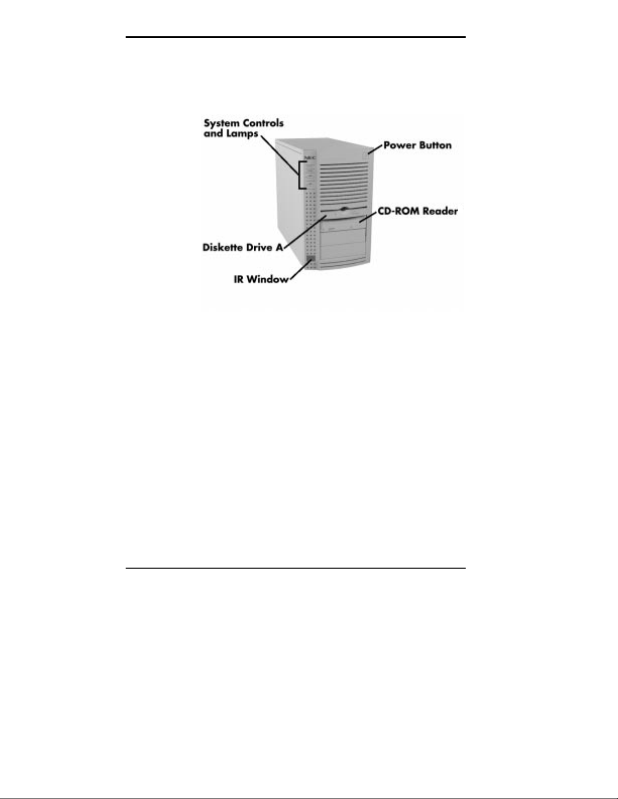
FRONT FEATURES
The following figures show the features on the front of the
system. A brief description follows the figures.
Front features
The following figure shows in detail the system controls and
lamps called out in the previous figure.
1-2 Introducing Your Computer
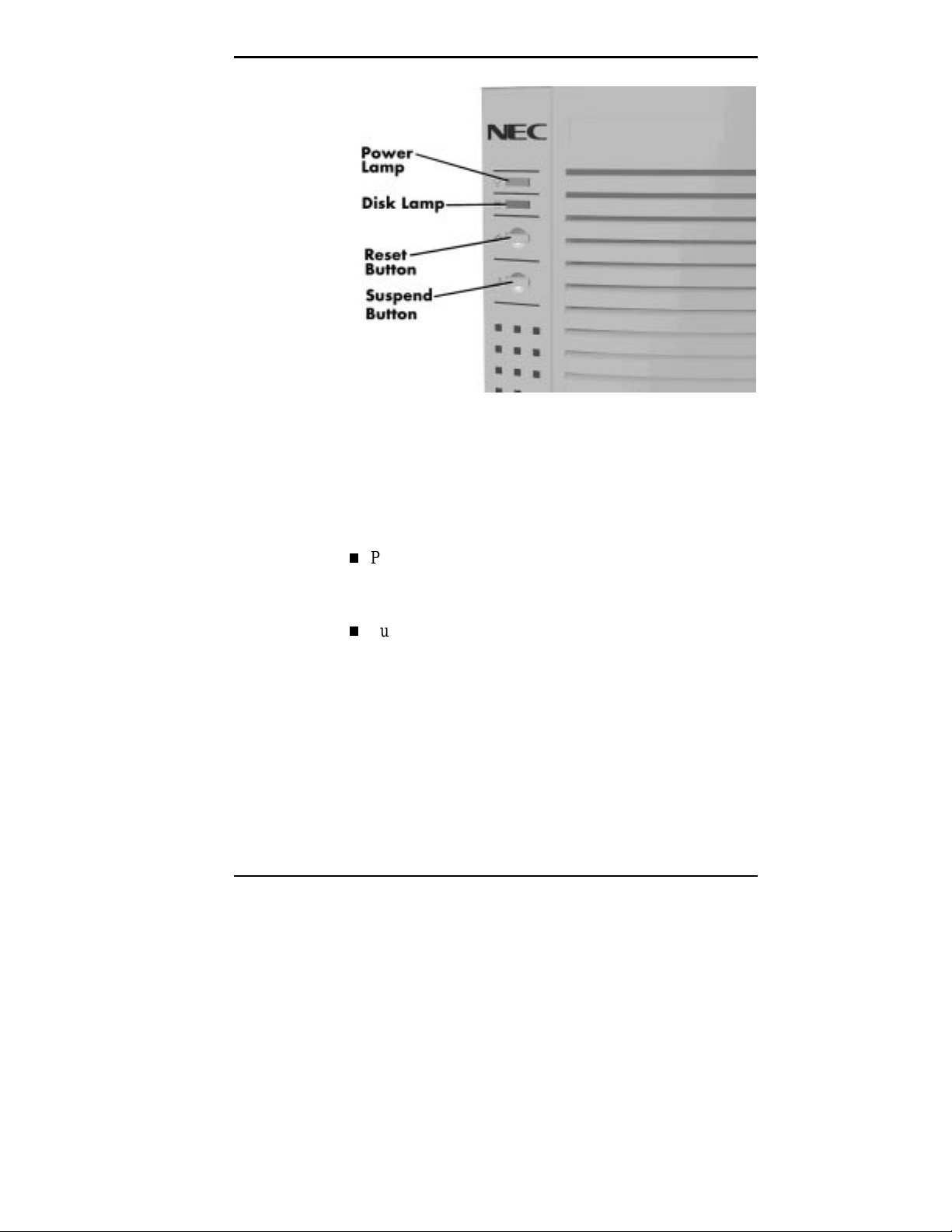
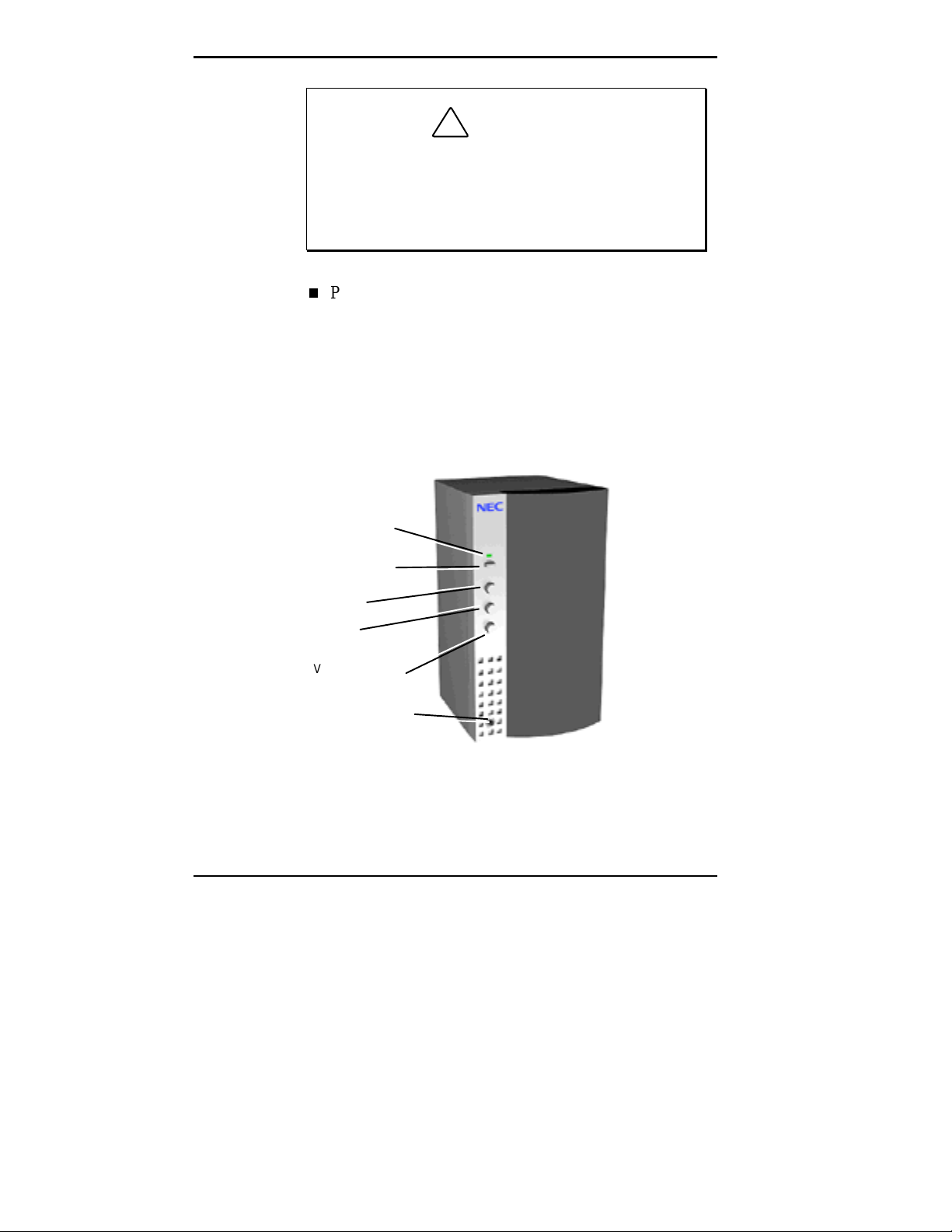
System Controls and Lamps
System controls let you select specific system operations.
Lamps let you know the status of system operation. Your
computer has the following controls and lamps:
System controls and lamps
Power button
Press this button to turn on system power. Press it again
to turn off the power.
Suspend button
Lets you initiate a power-saving mode of operating your
computer. Press this button to suspend system operation
when you plan to be away from your computer for a
short time. Press any key or move your mouse to resume
system operation to where you stopped it.
A blinking system unit power lamp lets you know that
the system is in a power-saving mode.
If you have a DDC-2 compliant monitor, your monitor
also will go into power-saving mode.
Introducing Your Computer 1-3
Reset button
The reset button lets you manually restart your system
when it does not respond to keyboard commands.
!
Resetti ng your system can resul t i n t he loss of dat a.
Press the reset button only when all other methods
of restarting your computer fails.
Power lamp
The power lamp indicates whether system power is on or
off. It also lets you know if the system is operating in a
power-saving mode.
A steady green lamp indicates that the power is on to all
system components. A blinking green lamp indicates that
the system is in Suspend mode with full power
reduction.
CAUTION
Disk lamp
Indicates whether or not your hard disk is active. A
green lamp tells you that the hard disk is reading or
writing data.
Do not turn off the system, unless absolutely
necessary, while the di sk l amp is lit. To do so can
damage your hard disk or data.
1-4 Introducing Your Computer
!
CAUTION
IR Window
The IR (infrared) window is the system’s IR port. The IR
port supports two-way wireless communications. The
interface uses infrared as the transmission medium instead
of a traditional cable.
The IR port lets you transfer files to or from portable
devices such as laptops and personal digital assistance
(PDA) products using application software supporting
IrDA data transfer. Your system comes with LapLink
software for wireless data transfer.
With IrDA software, you can transfer data at speeds of up
to 115 kilobytes per second and at distances up to 3 feet
from the IR window.
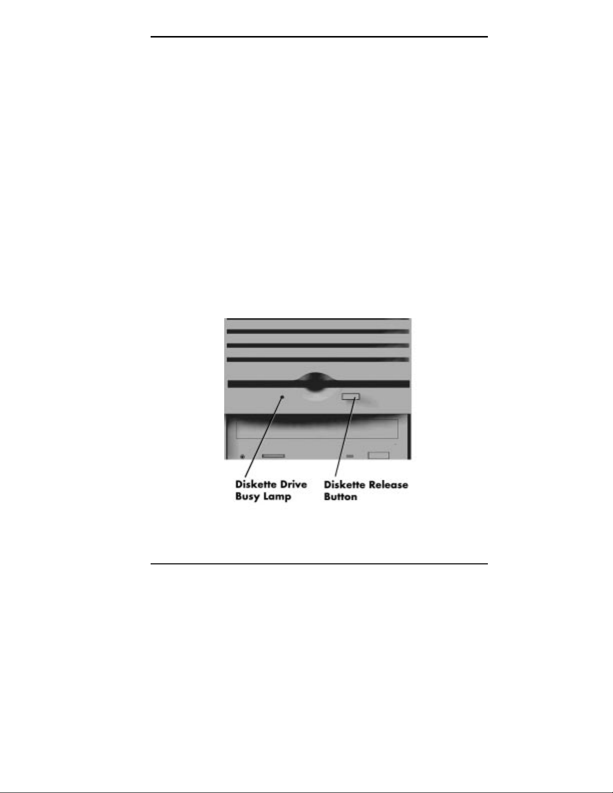
Diskette Drive A
Diskette drive A loads and starts programs from a diskette.
Diskette drive A is your primary “bootable” drive.
Diskette drive A features
Introducing Your Computer 1-5
Your diskette drive has the following features:
To prev ent damage to y our di skette dr iv e and data,
do not turn off the system or remove a diskette
while the diskette drive busy lamp is lit.
CD-ROM Reader
An eight-speed CD-ROM reader is a standard feature in
multimedia models. The CD-ROM reader is assigned as
drive F.
Diskette drive busy lamp
Lights when your diskette drive is reading to or writing
from a diskette.
!
CAUTION
Diskette release button
Press this button to release a diskette from the diskette
drive.
Use the CD-ROM reader to load and start programs from a
compact disc (CD). You can also use the CD-ROM reader
to play your audio CDs.
NOTE
You can boot your system f rom the CD- ROM
with a bootable CD. To enable the system to boot
from the CD-ROM, see “Boot Options” in Chapter 4.
The CD-ROM reader operates at different speeds depending
on whether the CD you are using contains data or music.
This allows you to get your data faster and to see smoother
animation and video.
1-6 Introducing Your Computer
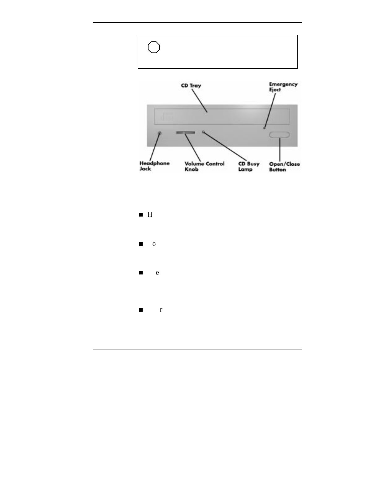
NOTE
The CD-ROM reader in your system might
look different from the one shown here.
CD-ROM reader features
The CD-ROM reader has the following features:
Headphone jack
Allows the connection of an optional set of headphones
with a stereo mini-jack plug.
Volume control knob
Lets you adjust the volume of an optional set of
headphones.
Open/close button
Opens or closes the reader’s loading tray. Press this
button when the computer power is on to insert or
remove a CD into or out of the reader.
Emergency eject hole
Allows the manual ejection of a CD if the eject function
is disabled by software or if a power failure occurs.
Introducing Your Computer 1-7
CD busy lamp
Lights when the reader is retrieving data, music, or
graphics/audio from a CD. Do not eject the CD or turn
off the system unit when the lamp is on.
CD tray
Provides a surface for loading a CD into the reader.
Press the open/close button to open or close the CD tray.
BACK FEATURES
On the back of your computer, you’ll find external
connectors, power supply features, and expansion board
slots.
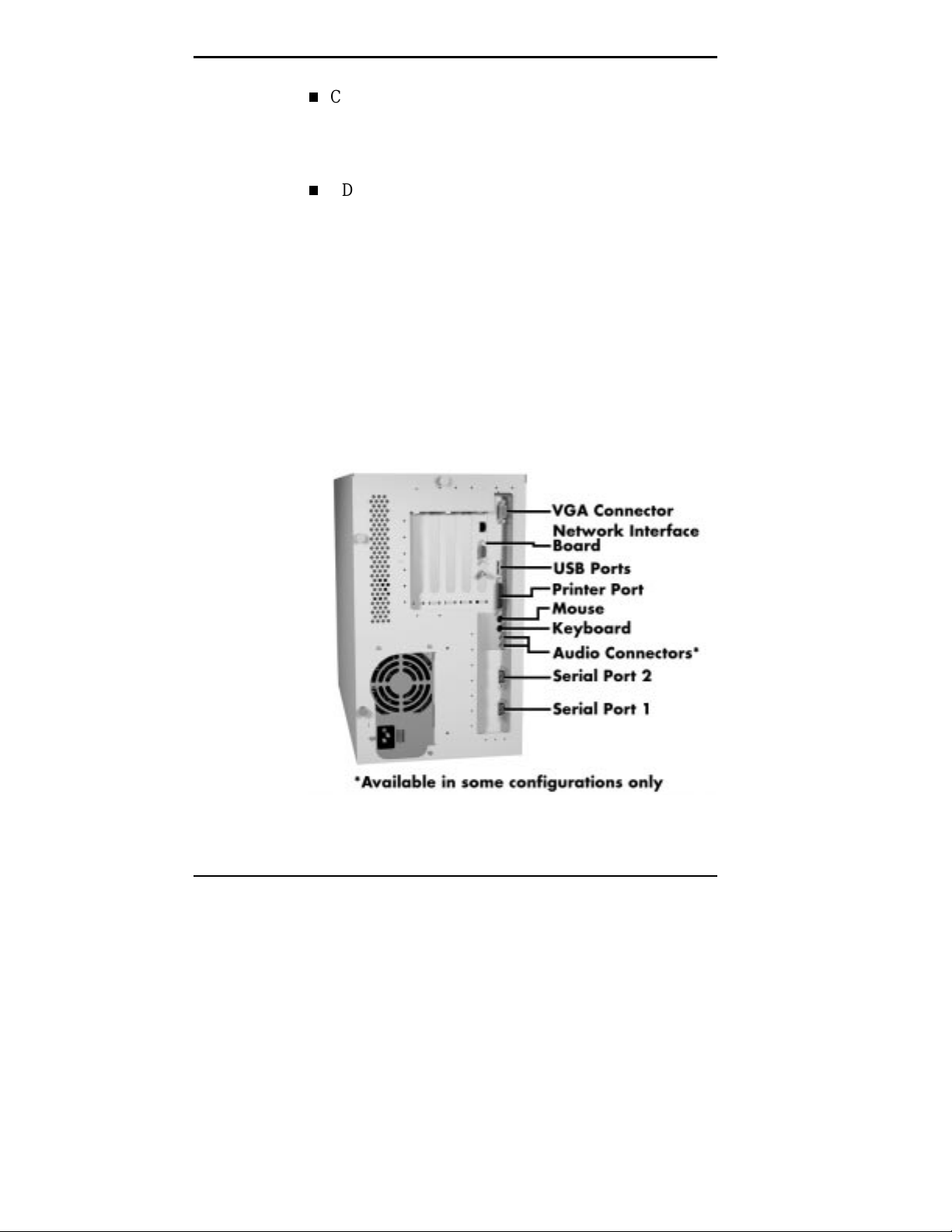
The following figure shows the connectors on the rear of the
computer. (The slot location of the network interface board
in your system might vary from the slot location shown on
the figure.)
1-8 Introducing Your Computer
Rear features
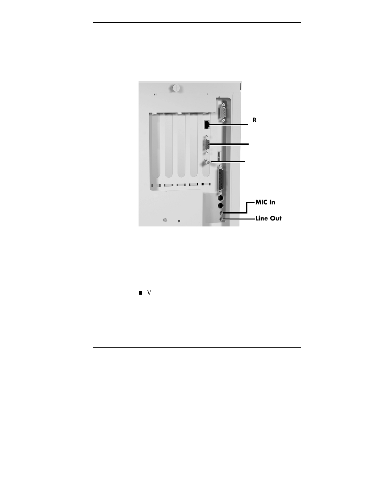
The following figure shows the audio connectors and
network interface board connectors that were called out
previously. (The slot location of the network interface board
in your system might vary from the slot location shown.)
RJ-45
Connector
AUI Connector
BNC Connector
External Connectors
External connectors let you attach peripheral devices, such
as a monitor, keyboard, mouse, and printer to your system.
Your system has the following external connectors:
VGA monitor connector
Attach the signal cable from your monitor to this
connector. Supports an NEC MultiSync
other video graphics array (VGA)-compatible monitor
with a 15-pin connector.
Audio and network board connectors
®
monitor or
Introducing Your Computer 1-9

Network interface board connectors
These connectors allow connection to an Ethernet
network and communications with other computers. The
board has three connectors for coaxial and twisted-pair
network cabling.
The BNC connector supports thin coaxial cables.
The AUI connector supports thick coaxial cables.
The RJ-45 connector supports twisted-pair
10BASE-T cables.
Universal Serial Ports (USB)
Use these ports to connect up to 126 daisy-chained
devices (monitors, communication devices, mass
storage, and more) directly to your system.
Printer Port
Use this port to connect a parallel printer with a 25-pin
connector to the system.
Mouse port
Attach the mouse that comes with your computer to this
port. The mouse port supports a PS/2-compatible
mouse.
Keyboard port
Attach the keyboard that comes with your computer to
this connector.
The keyboard port supports a personal system (PS)/2®compatible, 101-key or 104-key keyboard (in the U.S.
and Canada) or a 102-key keyboard (in the United
Kingdom and Germany) with a 6-pin mini DIN
connector.
1-10 Introducing Your Computer

Audio connectors
These connectors come integrated on multimedia models.
The connectors include microphone in and line out jacks.
The microphone in jack lets you connect a
microphone for recording audio information in your
data system files.
The line out jack allows you to connect an amplified
output device such as powered speakers, stereo tape
recorder, or an external amplifier for audio output.
Use this jack to connect the stereo speakers that
come with your system.
Serial Ports
Attach a serial device with a 9-pin connector to each
serial port. Serial devices include a pointing device,
serial printer, or modem.
Power Supply Features
Your system has the following power supply features:
Power supply fan
Keep this area clear for proper ventilation. The power
supply fan cools system components.
Voltage selector switch
Sets the voltage for your system to 115 volts or
230 volts.
Introducing Your Computer 1-11
SPEAKERS
!
Set the switch correctl y f or the v olt age in your ar ea.
Most wall outlets in the United States and Canada
are 115 vol t s. Out let s in Eur ope, Austr ali a, and Asi a
(except Taiwan) are 230 volts. T aiwan uses 115-volt
outlets.
Power socket
CAUTION
Connect your power cable to this socket.
Multimedia models come with a pair of high-quality,
20-watt stereo speakers that you can arrange to suit your
work environment.
Power Lamp
Power Button
Treble
Bass
Volume Control
Headphone Jack
1-12 Introducing Your Computer
Speaker

An AC adapter comes with the system. Set up the speakers
with the AC adapter. The speakers connect to the line out
jack on the back of the system unit.
The 20-watt speaker set features a power button, power
lamp, volume, treble and bass control knobs, and headphone
jack.
Adjust the speaker volume by using the volume control on
the front of the right speaker or by using the preinstalled
sound system software. Use the sound software to balance
the speakers.
The sound software is Voyetra Multimedia Sound Software.
See Chapter 6 for information on using the Voyetra sound
software.
Introducing Your Computer 1-13

MICROPHONE
The microphone allows you to record voice and sound into
your computer data files. See Chapter 6 for information on
recording sound using the Voyetra sound software.
Microphone
1-14 Introducing Your Computer

2
USING A MOUSE
Getting Started
This chapter provides the information you need to start
using your system. Information includes:
Using a Mouse
If you are already familiar with using a mouse, skip this
section.
Using Online Documentation
Read this section to use the comprehensive online system
documentation about your system.
Where to Go from Here
Look at this section for a quick reference to what you
can do and where you can go for information.
Use the mouse to quickly move around on the screen, to
select menu items, and to choose functions specific to your
software.
Here are the basic ways to use the mouse:
Click
Clicking selects an object on your screen. To “click,”
point to the object and press and release the left mouse
button.
Clicking the right mouse button on the Windows 95
desktop provides shortcuts to such features as the
Properties menu. See Using Windows 95 online guide
for more information on the uses for the right mouse
button.
Getting Started 2-1

Double click
Some actions require a double click to execute them. To
“double click” an object, point to the object and press
and release the left mouse button twice.
Press
Pressing the mouse button holds an action until you
release the mouse button.
Drag
Dragging your mouse attaches your pointer to an object
on the screen and allows you to highlight text or move
an object. To drag an object, point to the object, press
the left mouse button, and move the mouse to the new
location.
Typical screen objects that you click or double click are
icons, buttons, and menu options.
NOTE
If your mouse pointer disappears, m ove your
mouse in wide circles to bring it back into the
screen.
For more information about your mouse, see your online
User’s Guide and your application documentation. Also
included in the online documentation is information on
cleaning your mouse.
USING ONLINE DOCUMENTATION
Your system comes with documentation conveniently
available at your fingertips. No more looking for printed
documents. Information about your system is available right
from the Windows 95 desktop.
2-2 Getting Started
To access the online system documentation, locate NEC’s
PowerMate Online Documents group on the Windows 95
desktop. Double click NEC’s PowerMate Online
Documents icon. A welcome screen appears with the
information you need to use the online documentation.
The NEC PowerMate Series System Documentation is a
comprehensive source of information about your system. To
help you find the information you need, the documentation
is organized by topic and the following modules:
System Tour
User’s Guide
Product Information Center
Option Installation Center
Support Center.
NOTE
Run the online NEC PowerMate P ETC
Series System Documentation at the shipping
default video resolution — 800 by 600 with 256
colors with small fonts.
Other online documents include:
Healthy Environment
Access the document by clicking Start on the Windows
95 desktop and pointing to Programs and NEC
Information Center.
Using Windows 95
Access the document by clicking Start on the Windows
95 desktop and pointing to Programs, Modern Age
Books, and Windows 95.
Getting Started 2-3

Most of your application programs provide extensive online
help at the touch of a button (usually the Help button).
Some programs provide separate online user’s guides for
specific applications.
Windows 95 provides extensive online help and “wizards”
to guide you through procedures.
WHERE TO GO FROM HERE
Once you have your system up and running, we suggest that
you do the following:
See the online help file, “Setting Up a Healthy Work
Environment.”
Take the System Tour in your online NEC PowerMate P
ETC Series System Documentation.
See the online User’s Guide in your online NEC
PowerMate P ETC Series System Documentation.
Install any applications. See the documentation that
comes with the application.
2-4 Getting Started

See the following quick reference chart to find information
about some of the things you might want to do:
Quick Reference to Information About Your Computer
WHAT YOU WANT TO FIND WHERE TO FIND IT
Basic information about my
computer
Ask A.N.D.I.E.™ and
What On Earth
Online User’s Guide in the
ETC Series System Documentation
Online
System Tour in NEC PowerMate P ETC
NEC PowerMate P
Series System Documentation
Printed
Ingenius Ask A.N.D.I.E. and What On Earth
documentation
Microsoft® Office 97
Standard Edition
Setting a password “Setting a Password” in the online User’s Guide
Online
Online help for each application
NEC PowerMate P ETC Series System
(
Documentation)
Using Windows Online
Using Windows 95
Printed
Windows 95 User’s Guide
NEC PowerMate Customers
The
additional Windows 95 and MS-DOS 6.2
documentation.
Loading a CD “Loading a CD” in the online User’s Guide
NEC PowerMate P ETC Series System
(
catalog offers
Documentation)
Playing a music CD Multimedia models:
AudioStation online help
Chapter 6 in this guide
Using the suspend button “Saving Power” and “Managing Power” in the
online User’s Guide (
Series System Documentation
NEC PowerMate P ETC
)
Getting Started 2-5

C
Quick Reference to Information About Your Computer
WHAT YOU WANT TO FIND WHERE TO FIND IT
Adding options “Adding Internal Options” or “Adding External
Options,” in the online Option Installation
Center (
Documentation)
Chapter 3 in this guide
NEC PowerMate P ETC Series System
Understanding power
management
Access to the World Wide
Web
Transferring files from my
laptop to my computer via
the IR window
Protecting my system from
viruses
Changing video drivers “Changing Video Drivers” in the online User’s
“Saving Power” and “Managing Power” in the
online User’s Guide (
Series System Documentation
“Microsoft Internet Explorer” in the online System
NEC PowerMate P ETC Series System
Tour (
Documentation
LapLink online help and “Using the IR Port” in
the online User’s Guide (
NEC PowerMate P ETC
)
)
NEC PowerMate P ET
Series System Documentation)
“Scan95” and “WebScan” in the online System
NEC PowerMate P ETC Series System
Tour (
Documentation
Guide (
NEC PowerMate P ETC Series System
)
Documentation)
Using Desktop Management
Interface
Using support services “24-Hour Information Services” in the online
Taking care of my system “Taking Care of Your System” in the online
“Desktop Management Interface” in the online
Product Information Center (
ETC Series System Documentation
Support Center (
NEC PowerMate P ETC Series
System Documentation
Chapter 7 in this guide
User’s Guide (
NEC PowerMate P ETC Series
System Documentation
NEC PowerMate P
)
)
)
Troubleshooting tips Chapter 7 in this guide
2-6 Getting Started

3
Installing Options
Your system supports a variety of industry-standard and
NEC expansion options, including the following.
monitors − your system supports the connection of a
VGA-compatible monitor such as NEC MultiSync
and XP series.
SIMM memory − your system comes with 16-MB of
Extended Data Out (EDO) RAM upgradeable to
192 MB of 32- or 36-bit, 60-ns high-speed memory
using SIMM sticks.
video SGRAM − your system comes standard with
2 MB of video synchronous graphics random access
memory (SGRAM) that provides resolutions of up to
1280 by 1024 with 256 colors, 1152 by 864 with 32 K
colors, 1024 by 768 with 32 K colors, 800 by 600 with
16.7 million colors, or 640 by 480 with 16.7 million
colors.
®
XE
With an upgrade to 4 MB of video SGRAM, your
system supports resolutions of up to 1600 by 1200 with
32 K colors, 1280 by 1024 with 64 K colors, 1152 by
864 with 16.7 million colors, 1024 by 768 with 16.7
million colors, 800 by 600 with 16.7 million colors, or
640 by 480 with 16.7 million colors.
processor upgrade − a 320-pin zero insertion force (ZIF)
socket on the system board supports the primary
processor or an OverDrive processor for upgrades.
drives − your system supports a total of six storage
devices.
Installing Options 3-1

OPTION INSTALLATION PROCEDURES
This chapter provides installation instructions for the
following options:
expansion boards
SIMM memory upgrade
video memory upgrade
processor upgrade
data storage devices
external options.
All options require that the system cover be removed.
Procedures for removing the cover are included in this
chapter.
General Rules
Follow these general rules when you install the system
options.
3-2 Installing Options
Turn off system power and unplug the power cable.
Turn off and disconnect all peripherals.
When handling boards or chips, touch the system frame
to discharge static.
Do not disassemble parts other than those specified in
the procedure.
All screws are Phillips-head unless otherwise specified.
Label any removed connectors. Note where the
connector goes and in what position it was installed.

Safety Precautions
Take care when working inside the system and when
handling computer components. Avoid electric shock or
personal injury by observing the following warning.
Before remov ing the system unit cover, turn off the
power and unplug the system power cable. Power i s
removed only when the power cable is unplugged.
Static electricity and improper installation procedures can
damage computer components. Protect computer
components by following these safety instructions.
Electrostatic discharge can damage computer
components. Discharge stat ic el ectri cit y by touchi ng
a metal object before removing the system unit
cover.
!
WARNING
!
CAUTION
Avoid carpets in cool, dry areas. Leave an option, such
as a board or chip, in its anti-static packaging until
ready to install it.
Dissipate static electricity before handling any system
components (boards, chips, and so on) by touching a
grounded metal object, such as the system's unpainted
metal chassis.
If possible, use anti-static devices, such as wrist straps
and floor mats.
Installing Options 3-3

Always hold a chip or board by its edges. Avoid
touching the components on the chip or board.
Take care when connecting or disconnecting cables. A
damaged cable can cause a short in the electrical circuit.
Misaligned connector pins can cause damage to system
components at power-on.
When installing a cable, route the cable so it is not
pinched by other components and is out of the path of
the system unit cover. Prevent damage to the connectors
by aligning connector pins before you connect the cable.
When disconnecting a cable, always pull on the cable
connector or strain-relief loop, not on the cable.
Removing the System Unit Cover
The following procedure describes how to remove the
system unit cover.
!
Before remov ing the system unit cover, turn off the
power and unplug the system power cable. Power i s
removed only when the power cable is unplugged.
WARNING
1.
2.
3-4 Installing Options
Turn off and unplug the system unit.
Disconnect the keyboard, mouse, monitor, and any other
external options (such as a printer) from the rear of the
system unit.
Label all cables to make reinstallation easier.

!
Electrostatic discharge can damage computer
components. Discharge stat ic el ectri cit y by touchi ng
a metal object before removing the system unit
cover.
3.
Loosen the three thumb screws at the rear of the system
unit. If you installed a padlock on the back of the
system, unlock the padlock and remove it.
CAUTION
Loosening the cover screws
Installing Options 3-5

4.
From the rear of the system, grasp the handle and pull it
back so that the cover clears the padlock slot.
Releasing the cover
5.
6.
3-6 Installing Options
Lift up at the top of the cover to release the cover tabs
from the chassis.
Pull the cover up until it comes free of the chassis.

Replacing the System Unit Cover
Replace the system unit cover as follows.
1.
Insert the metal tabs on the top of the system cover into
their slots on the chassis.
2.
Insert the metal tabs on the bottom of the system cover
into their slots on the chassis.
Replacing the cover
3.
Slide the cover forward to meet the front panel.
NOTE
The cover fits tightly. If the cover does not
slide all t he way to the front panel , place one hand
on the front of the unit while you slide the cover
forward from the rear.
Installing Options 3-7

4.
Secure the cover with the three thumb screws.
5.
Reconnect all external peripherals.
6.
Plug in your power cables.
EXPANSION BOARDS
Your system supports industry standard 8- and 16-bit ISA
Plug and Play or non-Plug and Play, and 32-bit PCI
expansion boards.
With Plug and Play expansion boards, you can install a
board in an expansion slot without changing the hardware
settings. There are no system resource conflicts to resolve.
Plug and Play automatically configures the board for the
system.
3-8 Installing Options

Locating Expansion Slots
The system has five expansion slots.
two ISA slots
two PCI slots
one shared PCI/ISA slot
ISA expansion slots support industry-standard 8-bit or 16bit expansion boards. The PCI/ISA slot also supports PCI
expansion boards.
PCI expansion boards run at the system's processor speed.
The PCI bus handles 32 bits of data at a time, being wider
as well as faster than the standard ISA bus. PCI boards can
send and receive data much faster which boosts system
performance.
Locating expansion slots
Installing Options 3-9

Installing an Expansion Board
Install expansion boards in the system as follows.
1.
Remove the system unit cover.
2.
Follow any preinstallation instructions that come with
the board (such as setting switches or jumpers).
3.
Remove the screw securing an expansion slot cover and
remove the cover.
Save the screw for installing the expansion board. Save
the slot cover for future use.
!
A slot c over can damage the syst em board or any
option board i f it fall s into the system . Take car e to
keep the slot cover from f alling when rem oving the
screw.
CAUTION
3-10 Installing Options
Removing a slot cover

4.
Hold the board by its edges and insert it into the
expansion slot. Align full-size expansion boards with the
guide rail at the front of the system unit.
Press the board firmly into the expansion slot connector.
Gently rock the board from side-to-side to seat it into the
connector.
5.
Insert the screw removed earlier to secure the expansion
board to the support bracket.
Installing an expansion board
6.
Attach any signal cables required by the expansion
board.
7.
Replace the system unit cover.
Installing Options 3-11

Removing an Expansion Board
1.
Remove the system unit cover as previously described.
2.
Label and remove any cables connected to the board.
3.
Remove the screw that secures the board to the support
bracket.
4.
Pull the board out of the connector. Gently rock the
board from side-to-side to release it from its connector.
5.
6.
3-12 Installing Options
Removing the expansion board
Replace the slot cover removed when the expansion
board was installed.
Replace the system unit cover.

SYSTEM BOARD OPTIONS
Some of the options require locating the connector on the
system board. See the following figure for connector
locations.
System board sockets and connectors
SIMM UPGRADE
Your system comes with 16 MB of main system memory.
Six sockets on the system board support up to 192 MB of
high-speed memory using industry-standard, tin-plated,
single in-line memory modules (SIMM).
EDO SIMMs into the SIMM sockets.
See the following list for supported SIMMs.
NOTE
You can install 60-ns, parity or nonparity,
Installing Options 3-13

1-MB by 32- or 36-bit (4-MB stick)
2-MB by 32- or 36-bit (8-MB stick)
4-MB by 32- or 36-bit (16-MB stick)
8-MB by 32- or 36-bit (32-MB stick).
To avoid corrosion between different metals, only
use tin-plated SIMM sticks.
Checking System Memory
Use the following procedure to:
1.
check the memory installed in the system
2.
determine the SIMM configuration needed to increase
memory
!
CAUTION
3.
3-14 Installing Options
NOTE
SIMM memory must be installed in pairs of
the same memory type.
identify SIMM sockets.
Locate the six SIMM sockets on the system board
(see “System Board Options”).
If any cables block access to the SIMM sockets,
label and disconnect them. If any boards block access
to the sockets, remove them.
Use the following table to determine the SIMM
configuration needed to upgrade memory and to
identify the sockets for SIMM installation.

Recommended Memory Upgrade Path
TOTAL BANK 0 BANK 1 BANK 2
MEMORY SIMM 1 SIMM 2 SIMM 3 SIMM 4 SIMM 5 SIMM 6
8 MB 4 MB 4 MB Empty Empty Empty Empty
16 MB 4 MB 4 MB 4 MB 4 MB Empty Empty
16 MB* 8 MB 8 MB Empty Empty Empty Empty
24 MB 4 MB 4 MB 4 MB 4 MB 4 MB 4 MB
24 MB 8 MB 8 MB 4 MB 4 MB Empty Empty
32 MB 4 MB 4 MB 4 MB 4 MB 8 MB 8 MB
32 MB 8 MB 8 MB 8 MB 8 MB Empty Empty
32 MB* 16 MB 16 MB Empty Empty Empty Empty
40 MB 8 MB 8 MB 8 MB 8 MB 4 MB 4 MB
40 MB 16 MB 16 MB 4 MB 4 MB Empty Empty
48 MB 8 MB 8 MB 8 MB 8 MB 8 MB 8 MB
48 MB 16 MB 16 MB 4 MB 4 MB 4 MB 4 MB
48 MB 16 MB 16 MB 8 MB 8 MB Empty Empty
56 MB 16 MB 16 MB 8 MB 8 MB 4 MB 4 MB
64 MB 16 MB 16 MB 8 MB 8 MB 8 MB 8 MB
64 MB 16 MB 16 MB 16 MB 16 MB Empty Empty
64 MB 32 MB 32 MB Empty Empty Empty Empty
72 MB 32 MB 32 MB 4 MB 4 MB Empty Empty
72 MB 16 MB 16 MB 16 MB 16 MB 4 MB 4 MB
80 MB 32 MB 32 MB 4 MB 4 MB 4 MB 4 MB
80 MB 16 MB 16 MB 16 MB 16 MB 8 MB 8 MB
80 MB 32 MB 32 MB 8 MB 8 MB Empty Empty
*Standard configuration.
Installing Options 3-15

Recommended Memory Upgrade Path
TOTAL BANK 0 BANK 1 BANK 2
MEMORY SIMM 1 SIMM 2 SIMM 3 SIMM 4 SIMM 5 SIMM 6
88 MB 32 MB 32 MB 8 MB 8 MB 4 MB 4 MB
96 MB 32 MB 32 MB 8 MB 8 MB 4 MB 4 MB
96 MB 16 MB 16 MB 16 MB 16 MB 16 MB 16 MB
96 MB 32 MB 32 MB 16 MB 16 MB Empty Empty
112 MB 32 MB 32 MB 16 MB 16 MB 8 MB 8 MB
128 MB 32 MB 32 MB 32 MB 32 MB Empty Empty
128 MB 32 MB 32 MB 16 MB 16 MB 16 MB 16 MB
136 MB 32 MB 32 MB 32 MB 32 MB 4 MB 4 MB
144 MB 32 MB 32 MB 32 MB 32 MB 8 MB 8 MB
160 MB 32 MB 32 MB 32 MB 32 MB 16 MB 16 MB
192 MB 32 MB 32 MB 32 MB 32 MB 32 MB 32 MB
Removing a SIMM
Use the following procedure to remove a SIMM.
1.
2.
3.
3-16 Installing Options
!
Reduce static discharge by touching the system's
metal chassis.
CAUTION
Remove the system unit cover.
Locate the SIMM sockets (see “System Board
Options”).
Press the metal clips at the outer edges of the socket
away from the SIMM.

4.
Push the SIMM away from the locking tabs and remove
it from the socket.
Use the following procedure to install a SIMM stick.
Installing a SIMM
Install a SIMM as follows.
Removing a SIMM
1.
Remove the system unit cover.
2.
Locate the SIMM sockets (see “System Board
Options”).
Remove any currently installed SIMMs that are not
needed.
!
Bef ore instal l ing a S IMM , reduc e stati c di scharge by
touching the system's metal chassis.
CAUTION
Installing Options 3-17

3.
Install the SIMMs from the back to the front.
4.
Align the notched end of the SIMM with the left side of
the SIMM socket as shown in the following figure.
5.
Insert the SIMM at an angle into the socket.
6.
Tilt the SIMM towards the locking tabs using equal
pressure at the ends of the SIMM until it locks into the
socket.
7.
8.
3-18 Installing Options
Inserting the SIMM
Replace any cables or boards that may have been
removed.
Replace the system unit cover.

VIDEO UPGRADE
Upgrade the video memory by adding a 3-MB upgrade
SGRAM module as follows.
NOTE
SGRAM (includes a 1-MB modul e). To upgrade to
4 MB, you must replace your 1-MB module with a
3-MB upgrade module.
1.
Remove the system unit cover as previously described.
2.
Locate the video SGRAM sockets (see “System Board
Options”).
If any expansion boards are obstructing your view of the
sockets, remove the boards (see “Removing an
Expansion Board”).
Your system comes standard with 2 MB of
!
Reduce static discharge by touching the system's
metal chassis.
3.
Align the module over the sockets on the system board.
CAUTION
Using equal pressure, gently press the module into the
sockets.
Installing Options 3-19

Aligning the video SGRAM module with the sockets
4.
Replace any boards that were removed.
5.
Replace the system unit cover.
3-20 Installing Options

PROCESSOR UPGRADE
The zero-insertion force (ZIF) socket accepts pin-grid-array
(PGA) processors, such as the primary processor or an
OverDrive processor.
Incorrect installation of the processor can damage
the processor, system board, or both. Follow the
installation instructions carefully.
The system requires a heatsink on the OverDrive
processor. Verif y that you hav e the correct heatsink
for the processor.
When upgrading the processor, first remove the processor
currently installed in the system, then install the OverDrive
processor.
!
CAUTION
Removing the Processor
Remove the processor installed on the system board as
follows.
1.
Remove the system unit cover.
2.
Locate the processor socket (see “System Board
Options”).
If any expansion boards are obstructing the socket,
remove the boards.
3.
Release the heatsink clip from the tabs on the socket.
4.
Release the processor by pulling the lever on the socket
away from the socket and as far back as it goes without
forcing.
Installing Options 3-21

Releasing the processor
!
Before picking up the processor, reduce static
discharge by touching the metal frame of the
system unit.
CAUTION
5.
6.
3-22 Installing Options
Lift the processor out of the socket.
Continue with the following procedure to install the new
OverDrive processor.

Installing the Processor
1.
Remove the processor currently in the system (see
previous procedure).
Bef ore pi cking up the Over Drive processor, reduce
static discharge by t ouching the metal frame of the
system unit.
2.
Align the notched corner of the OverDrive processor
with the alignment corner in the socket and insert the
processor.
!
CAUTION
Aligning the processor
3.
Swing the lever down to lock the OverDrive processor
into the socket.
Installing Options 3-23

Remem ber to eit her reatt ach the heatsink used with
the old processor or install the new heatsink
supplied with the OverDrive processor.
4.
Check to see if the newly installed OverDrive processor
requires a system board jumper change (see Chapter 5,
“Setting System Board Jumpers”).
5.
Replace any boards removed during this procedure.
6.
Replace the system unit cover.
DATA STORAGE DEVICES
The system board in the computer supports the following
storage devices:
up to two diskette drives, including the standard
1.44-MB diskette drive
!
CAUTION
Other storage devices might require the installation of a
compatible controller board.
3-24 Installing Options
up to four IDE devices such as IDE hard disks and an
IDE CD-ROM reader.

3
Installing Options
Installing Options 3-23

3-24 Installing Options

Locating Device Slots
The system has six storage device slots:
a 3 1/2-inch accessible device slot which contains the
standard 1.44-MB diskette drive
two internal 3 1/2-inch internal hard disk drive slots
(1-inch high, thin-height)
three 5 1/4-inch accessible device slots (1.6-inch high,
half-height)
In multimedia models, one accessible device slot
contains the standard CD-ROM reader.
Other accessible devices (diskette drive, tape drive,
CD-ROM reader) can be installed in the 5 1/4-inch slots.
A hard disk with a 5 1/4-inch form factor can be
installed in the 5 1/4-inch slots.
Locating device slots
Installing Options 3-25

Preparing the Device
Before installing a storage device in the system, follow any
preinstallation instructions that come with the device. For
example, check the following:
Diskette drive remove any termination on the optional
diskette drive. See the documentation that comes with
the drive.
IDE device check the jumper settings on the device
before installing it. See the documentation that comes
with the device for jumper setting information.
An IDE device, such as an IDE hard disk or IDE CDROM reader, must be set correctly as the first (master)
or second (slave) device on the IDE channel.
The standard IDE hard disk is set as the master device
on the primary IDE connector. The CD-ROM reader in
multimedia models is the master device on the secondary
IDE connector.
Device Cables
The cables used for installation of optional storage devices
include:
The diskette drive and IDE cables shipped with the system
each support two devices. Cable connector locations on the
system board are shown in the following figure.
3-26 Installing Options
diskette drive signal cable
IDE signal cables
system power cables.

Diskette Drive Signal Cable
A three-connector diskette drive signal cable comes attached
to the system board and to the standard 1.44-MB diskette
drive.
System board cable connectors
The installation of a second diskette drive in your system
does not require the replacement of the existing diskette
drive signal cable. Connect an optional diskette drive to the
middle connector on the standard diskette drive signal cable.
The colored edge of the cable goes to pin 1 on the cable
connector. Align the red edge of the cable with pin 1 (the
notched end) on the drive connector.
Installing Options 3-27

The following figure shows a three-connector diskette drive
signal cable.
Diskette drive signal cable
IDE Signal Cables
Hard disk systems come with a three-connector IDE
interface cable attached to the primary IDE connector.
Multimedia systems come with a second IDE cable
connected to the CD-ROM reader and to the secondary IDE
connector.
Each IDE connector on the system board supports two IDE
devices. The addition of an IDE device to an IDE connector
does not require the replacement of the existing IDE signal
cable.
If installing an optional IDE CD-ROM reader, connect it to
the secondary IDE connector. The primary IDE port should
be reserved for hard disks.
3-28 Installing Options

The following figure shows a typical three-connector IDE
cable. If the IDE cable is not keyed with a connector tab,
align the colored edge of the cable with the pin 1 side of the
drive connector.
IDE cable connectors
Installing Options 3-29

System Power Cables
Power cables come from the power supply and are attached
to the standard storage devices. System power cables vary
in length and provide connector sizes to accommodate a
variety of supported storage configurations. Power cable
connectors are keyed to fit only in the correct position. The
following figure shows the power cable connectors.
Cabling Storage Devices
All storage devices require a power and signal cable
connection. Devices shipped with the system are already
connected.
Procedures are provided on the following optional devices:
IDE devices − hard disk drive or CD-ROM reader
diskette drive − 1.2-MB drive.
3-30 Installing Options
Power cable connectors

IDE Device Cabling
The following procedure explains how to cable an IDE
device.
Connect the signal cable connector to the connector on
1.
the IDE device.
Take care to prevent bending drive connector pins. Align
the cable connector as shown in the following figure.
Locate an available power connector coming from the
2.
power supply.
Connect the appropriate power cable to the power
3.
connector on the IDE device.
Connecting IDE device cables
If you are installing a CD-ROM reader, also connect the
4.
audio cable (see the instructions that come with the
reader).
Installing Options 3-31

Diskette Drive Cabling
Connect the diskette drive signal cable connector to the
1.
signal connector on the diskette drive as shown in the
following figure.
Locate an available power connector.
2.
Connect the power cable to the power connector on the
3.
device.
3-32 Installing Options
Connecting 1.2-MB diskette drive cables

Installing Storage Devices
The following subsections describe how to install 3 1/2-inch
and 5 1/4-inch drives. The installation procedures include:
installing the 3 1/2-inch hard disk drive
removing the side panel
removing the front panel
installing a 5 1/4-inch device
replacing the front and side panels.
Installing the 3 1/2-Inch Hard Disk Drive
Install the hard disk drive into the rear slot as follows.
Remove the system unit cover.
1.
Follow the preinstallation instructions that come with the
2.
device, such as setting jumpers and switches.
Remove and label any cables that interfere with
3.
installing the device.
Installing Options 3-33

To install the internal hard disk drive, you must first
4.
remove the power supply.
Remove the power supply as follows.
Locate the power supply as shown.
Locating the power supply
3-34 Installing Options
Disconnect the power supply cables from the system
board.

Remove the power supply screws.
Removing the power supply
Lift the power supply out of the system unit.
Align the holes in the hard disk drive with the holes at
5.
the bottom of the unit.
Installing Options 3-35

Secure the device to the bottom of the system unit.
6.
Securing the 3 1/2-inch drive
Connect the drive cables.
7.
Replace the power supply and reattach the power
8.
supply cables to the system board.
9.
10.
11.
3-36 Installing Options
Replace the four screws.
Replace the system unit cover. See “Replacing the
System Unit Cover.”
Run the Setup program to set the new configuration.

Removing the Side Panel
Remove the side panel only if you are installing a 5 1/4-inch
device in the top slot. (The second and middle slots install
using rails from the front.) The side panel does not need to
be removed if you are installing a 3 1/2-inch hard disk
drive.
If you are installing a 3 1/2-inch hard disk drive (see
“Installing the 3 1/2-Inch Drive”).
Remove the system unit cover as previously described.
1.
Remove the side panel by removing the two screws from
2.
the top of the panel.
Removing the side panel
Installing Options 3-37

Removing the Front Panel
Remove the front panel only if you are installing a
5 1/4-inch device. The front panel does not need to be
removed if you are installing a 3 1/2-inch hard disk drive.
Remove the front panel by releasing the six tabs from
1.
the back of the front panel.
2.
3.
3-38 Installing Options
Removing the front panel
Identify the slot for the device being installed.
Remove the blank panel from the selected slot by
pressing the panel tabs from inside the front panel and
pushing the blank panel out.

Remove the slot cover from the selected slot on the
4.
chassis.
Removing the slot cover
Install the device (see the following section “Installing
5.
the 5 1/4-Inch Device”).
Installing the 5 1/4-Inch Device
Install an accessible device into the device cage as follows.
Follow the preinstallation instructions that come with the
1.
device, such as setting jumpers and switches.
If installing the device in the middle or top slots, go to
2.
Step 4. Otherwise, continue with Step 3.
Attach rails to the sides of the device.
3.
Installing Options 3-39

Attaching device rails
From the front of the system, insert the device, connector
4.
end first, into the device slot.
NOTE
To easily access device connectors for
cabling, do not insert a 5 1/ 4-i nch devi ce al l t he way
into the slot.
5.
6.
3-40 Installing Options
Connect the device cables.
Secure the device as follows.
If installing in the top slot, align the holes in the
device with the holes in the side of the system unit.
Secure the device to the system with the four screws,
two to a side, that come with the device.
If installing in the middle and bottom slots, secure the
device to the system from the front with the two
metal slot cover screws.

Replacing the Side and Front Panels
To replace the front and side panels, follow this procedure.
Align the four front panel tabs with the holes in the front
1.
of the system unit.
Securing the device
Evenly press the front panel into position until the tabs
2.
lock the panel in place.
Installing Options 3-41

Aligning the front panel
Replace the side panel, and reinsert the screws to hold
3.
the panel in place.
Replace the cover. See “Replacing the System Unit
4.
Cover.”
Run the Setup program to set the new configuration.
5.
3-42 Installing Options

ADDING EXTERNAL OPTIONS
This subsection includes installation procedures for the
following external options:
parallel printer
serial devices.
Connecting a Parallel Printer
NOTE
Before connecti ng a pri nt er to t he system , be
sure the printer is set up correctly. Follow the setup
instructions that come with the printer.
Connect a parallel printer to the system as follows.
Turn off power to the system and printer.
1.
Connect the printer cable to the printer port on the rear
2.
of the system unit.
Installing Options 3-43

Secure the cable with the screws provided.
3.
Connect the other end to the printer.
4.
Connecting an RS-232C Device
Connecting a printer cable
1.
2.
3-44 Installing Options
NOTE
Before connecting a serial device to the
system, be sure the serial devi ce i s set up c orrect l y.
Follow the setup instructions that come with the
option.
Turn off power to the system and to the serial device.
Connect one end of the serial cable to one of the two
serial ports on the rear of the computer.

Connecting an RS-232C cable
Secure the cable with the screws provided.
3.
Connect the other end to the serial device.
4.
Installing Options 3-45

Setting System
4
THE SETUP UTILITY
Parameters
This chapter provides information on the NEC utilities that
ship with your system. The following topics are covered in
this chapter.
Setup utility
Flash utility
Product Recovery utility (multimedia systems only)
The Setup utility program allows you to enter system
configuration information and control special features of the
system.
NOTE
correct system parameters for your configuration.
Unless you add optional har dware, you do not need
to run Setup to oper ate your system . However , you
might wish to run the Setup utility to set features
that customize your system, such as security
features.
Your system ships from the factory with the
Setting System Parameters 4-1

System configuration information is stored in nonvolatile
memory. A nonvolatile memory device retains its data when
system power is turned off. Nonvolatile memory in your
system is a complementary metal-oxide semiconductor
(CMOS) chip backed up by a battery on the system board.
The battery supplies continuous power to CMOS memory
and maintains configuration information when system
power is off (see “Replacing the CMOS Battery ” in
Chapter 7).
NOTE
down your current Setup parameters and store the
information in a safe place. This lets you restore
your system to the current parameters if you ever
need to replace the battery.
When to Use Setup
The Setup utility lets you view and set system parameters.
Use the Setup utility program to
NEC recommends that you print out or write
set the time and date.
update or check system parameters when you add or
remove expansion options.
change or set power management features.
correct a hardware discrepancy when the Power-On
Self-Test (POST) displays an error message and
prompts you to run Setup.
check the installation of optional memory by comparing
the amount of memory installed with the amount of
memory displayed by Setup.
change certain system operating parameters, such as
boot device sequence and keyboard parameters.
4-2 Setting System Parameters

configure system connections for peripherals such as
your diskette drive, hard disks, and devices connected to
the printer port and serial ports.
customize your system with security features such as
passwords, diskette drive restriction, virus check
reminder and system backup reminder.
set system parameters in the event that you need to
replace the complimentary metal oxide semiconductor
(CMOS) battery.
How to Start Setup
To start the Setup utility, follow these steps:
1.
Turn on or reboot the system.
2.
Press
F1
after POST, but before the system boots up, to
start the memory test.
F1
There is about five seconds to press
before the
system boot continues.
3.
Setup’s Main Menu appears and looks similar to the
following screen.
Setting System Parameters 4-3

Main Advanced Security Exit
System Date 03:14:1997 F1 Help
System Time 08:12:20 ESC Back
Enter Select
Floppy Options Press Enter
Primary IDE Master IBM-DAQA-32160
Primary IDE Slave Not Installed
Secondary IDE Master Not-Installed
Secondary IDE Slave Not-Installed
Language English (US) F5 Setup Defaults
Boot Options Press Enter F6 Previous Values
F10 Save & Exit
Video Mode EGA/VGA
Mouse Installed
Base Memory 640
Extended Memory 15360
BIOS Version XX.XX
Previous Item
↑
Next Item
↓
Select Menu
←→
How to Use Setup
Use the keys shown on the right of the Setup menu to make
your selections or exit the current menu. The following
table describes the navigation keys and their alternates.
Main Menu
Key
F1 Provides help for the parameter field
Esc Exits the menu.
Enter Executes Command or Selects
↓ or ↑ arrow keys
4-4 Setting System Parameters
Navigation Keys
Function
being displayed.
submenu.
Moves cursor up and down.

Navigation Keys
Key Function
MAIN MENU
← or → arrow
keys
F5 Loads the Default Configuration values
F6 Selects the Previous Value for the field.
F10 Save and Exit
Selects next menu.
for this menu.
To display a submenu, use the arrow keys to move the
Enter
cursor to the submenu you want. Then press
.
The following is a list of available options when you select
the Main Menu in the legend bar. Other Main Menu options
are available by selecting submenus.
NOTE
See How to Start Set up for a look at a typic al
Main menu screen.
Use the arrow keys to select one of the following Main
Menu options and press
Enter
to select a submenu. Items
with grayed-out text are not available. Explanations of each
menu item follow.
System Date/Time
Diskette Drive
IDE Devices
Language
Boot Options
Setting System Parameters 4-5

Video Mode
Mouse
Base Memory
Extended Memory
BIOS Version
System Date/Time
Use this menu to set the current time and date. The settings
remain in memory even after you turn off the system power.
To set the date, enter the current month, day, and year in
mm/dd/yyyy format.
To set the time, enter the current hour, minute, and seconds
in hh:mm:ss, 24-hour format. For example, type
for 1:30 P.M.
Diskette Drive
This menu selects the type of diskette drive in your system.
Unless you are changing your hardware, you do not need to
change the diskette drive (floppy) A or B settings.
13:30:00
If you add an optional 5 1/4-inch diskette drive to your
system, select “Floppy B” and change the parameter to
“1.2 MB, 5.25 inch.”
IDE Devices
The hard disk drive (drive C:) is configured as “Primary
IDE Master.” This field reports the presence of an
identification string supported by up to four physical IDE
drives (two on each PCI/IDE connector). If the cursor is
placed on one of these fields and the field is selected by
pressing the
This submenu lets you set the drive parameters.
4-6 Setting System Parameters
Enter
key, the IDE Device Submenu appears.

Jumper settings on the IDE device must be set to the master
or slave device (see the documentation that comes with the
device).
IDE Device Configuration Submenu
The IDE Device Submenu lets you check or change the
following hard disk drive parameters.
IDE Device Configuration
Number of Cylinders
Number of Heads
Number of Sectors
Maximum Capacity
IDE Translation Mode
Multiple Sector Setting
Fast Programmed I/O Modes
IDE Device Configuration
The system is shipped with the default as “Auto
Configured” selected in this submenu. The system then
automatically detects the hard disk type and sets the
remaining parameters.
If your IDE hard disk does not feature auto IDE type
detection or your IDE hard disk was formatted on another
system with parameters different than those reported by the
drive, you need to select “User Definable,” and set the
“Number of Cylinders,” “Number of Heads,” “Number of
Sectors,” and Maximum Capacity.”
Setting System Parameters 4-7

IDE Translation Mode
The IDE Translation Mode parameter controls the way in
which the BIOS interacts with the drive in terms of drive
geometry. Proper choice is dependent upon the drive’s size,
capabilities, and the operating system (OS) used. The
following choices are available.
Standard CHS
−
is the translation mode that has been in
use for years. Its use limits IDE capacity to a maximum
of 528 MB regardless of the size of the drive used.
Logical Block
−
mode overcomes the 528 MB maximum
size limitations imposed by the Standard CHS mode. It
should be used only when the drive supports logical
block addressing (LBA), and the OS supports LBA, or
uses the BIOS to access the disk.
Extended CHS
−
mode also overcomes the 528 MB
maximum size limitations imposed by the Standard CHS
mode. It can be used with drives which are larger than
528 MB, but do not support the LBA mode.
Auto Detected (default)
−
allows the BIOS to examine
the drive and determine the optimal mode. The first
choice is to use Logical Block mode if it is supported by
the drive. The second choice is to use Extended CHS
mode if the drive topology allows. If neither of the above
two methods are possible, then Standard CHS mode is
used.
4-8 Setting System Parameters

!
When set to Auto Detected, the BIOS will detect
what the drive is capable of, not the translation
mechanism which was used to format the drive.
If a drive i s run i n a mode other than the mode i n
which it was partitioned and formatted,
unpredictable results may occur, including data loss.
Different OS’s have different abilities regarding IDE
translation modes:
CAUTION
You will get better performance not using “Fast 32-bit
IDE” if using a drive which employs Mode 3 PIO on the
PCI interface, unless using a version of WDCDRV.386
which supports these advanced modes.
−
UNIX
and must use the Standard CHS method. UNIX can
support drives larger than 528 MB, but does so in a
different manner.
OS/2 2.1 and OS/2 WARP
or Standard CHS methods. Note that LBA support may
require a switch setting on an OS/2 drive in order to
operate in the mode.
OS/2 2.0 and Novell Netware
ECHS or Standard CHS methods, but not LBA.
DOS and Windows
Standard CHS methods. If the “Fast 32-bit IDE” option
of Windows is used, make sure to use the Standard CHS
setting only, unless a version of WDCDRV.386 is being
used which supports this advanced geometry.
does not currently support either LBA or ECHS
−
can support LBA, ECHS,
−
can support either,
−
can support LBA, ECHS, or
Setting System Parameters 4-9

Language
The installed language will appear in the Setup and BIOS
text strings. English (US) is the default in the U. S. and
Canada.
Boot Options
When the cursor is placed in the Boot Option field, you can
select it by pressing
appears allowing parameters which affect the boot process
to be set.
Boot Options Submenu
The Boot Options Submenu lets you check or change the
following bootup parameters.
Boot Sequence
System Cache
Boot Speed
Num Lock
Setup Prompt
Hard Disk Pre-Delay
Typematic Rate Programming
Scan User Flash Area
Boot Virus Detection
Enter
. The Boot Options Submenu
Boot Sequence
The BIOS attempts to load the operating system in the
sequence listed here. The defaults are as follows.
First boot device
Second boot device
Third boot device
Fourth boot device
4-10 Setting System Parameters
−
Floppy
−
−
CD-ROM
−
Hard Disk
Disabled

System Cache
Boot Speed
The default for the System Cache field is “Enabled.” This
field controls both the primary and secondary caches.
Setting the system cache to “Disabled” will hurt
performance, but might be required when running software
which uses software timing loops and needs to be slowed
down to execute properly.
Boot speed refers to the system CPU cycles. The default
boot speed is “Turbo.” “De-turbo” mode slows the CPU by
disabling the system cache and adding increased refresh
cycles.
NOTE
“De-turbo” does not reduce the CPU speed to
8 MHz. If “De-turbo” is selected it will automatically
Disable” the System Cache.
“
Num Lock
Setup Prompt
The Num Lock field controls whether the Num Lock key on
the keyboard will be “On” or “Off” at bootup. The default
is “On.”
The Setup Prompt field allows you to disable the “Press
<F1> Key To Enter Setup” message displayed during
POST. It does not control access, just the message. This
field can be either “Enabled” or “Disabled.” The default is
“Enabled.”
Setting System Parameters 4-11

Hard Disk Pre-Delay
The Hard Disk Pre-Delay field causes the BIOS to wait a
specified time before accessing the first hard disk drive.
Setting a pre-delay provides the system with some time to
identify any additional drives before the standard hard drive
initializes. The default is “Disabled.” The delay times are as
follows.
3 seconds
6 seconds
9 seconds
12 seconds
15 seconds
21 seconds
30 seconds
Disabled (default)
Typematic Rate Programming
The parameter controls whether the default user
configuration values are used for Typematic Rate Delay
and Typematic Rate. The field is set as Default.
Default
Typematic Rate to 15.
Override
options allow you to customize the values.
Typematic Rate Delay
The Typematic Rate Delay field controls how long it takes
for the keyboard auto-repeat function to start when a
keyboard key is held down. The delay times are as follows.
250 msec (default)
500 msec
4-12 Setting System Parameters
−
sets the Typematic Delay to 250 msec and
−
provides the following two options. These

750 msec
1000 msec
Typematic Rate
The Typematic Rate field controls the speed characters
repeat when you hold down a keyboard key. The higher the
number the faster the repeat. The delay times are as follows:
6 char/sec (default)
8 char/sec
10 char/sec
12 char/sec
15 char/sec
20 char/sec
24 char/sec
30 char/sec.
Scan User Flash Area
Allows a user’s program to scan the user Flash area for
user data. Can be set as “Disabled” or “Enabled.” The
default is “Disabled.”
Boot Virus Detection
Enables an anti-virus program resident in the BIOS to scan
for any virus in the system. The program can also repair the
virus-infected area. The default is “Enabled.”
Video Mode
This field cannot be entered, it is an information field only.
The system has a video controller, the default is
“EGA/VGA.”
Setting System Parameters 4-13

Mouse
This field cannot be entered, it is an information field only.
The system supports a PS/2 mouse. If the mouse is not
installed the field will not be displayed. The default is
“Installed.”
Base Memory
This field cannot be entered, it is an information field only.
The system uses 640 KB of base memory.
Extended Memory
This field cannot be entered, it is an information field only.
Displays the amount of system memory above 1 MB.
BIOS Version
This field cannot be entered, it is an information field only.
Reports the BIOS identification string.
ADVANCED MENU
Selecting “Advanced” from the menu bar on the Main Menu
displays a menu with the following options. Use the arrow
keys to select an item from the Advanced menu and press
Enter
. Explanations of each topic follow.
Processor Type
Processor Speed
Cache Size
Peripheral Configuration
Advanced Chipset Configuration
Power Management Configuration
Plug and Play Configuration
Event Logging Configuration
4-14 Setting System Parameters

Setting items in this menu to incorrect values can
cause your system to malfunction.
Processor Type
This field cannot be entered, it is an information field only.
The processor is a Pentium processor that is backward
compatible with 8086, 80286, Intel 386, and Intel 486
processors.
Processor Speed
This field cannot be entered, it is an information field only.
The processor operates at the rated internal and external
speeds.
Cache Size
This field cannot be entered, it is an information field only.
!
CAUTION
Peripheral Configuration
When the cursor is placed in the Peripheral Configuration
field, you can select it by pressing
Submenu appears for setting parameters that affect the IDE
devices, diskette drive, serial ports, and parallel port.
Peripheral Submenu
The Peripheral Submenu lets you check or change the
following peripheral parameters.
Enter
. The Peripheral
Setting System Parameters 4-15

IDE Interface (Primary and Secondary)
The Primary and Secondary IDE Interface fields enable the
IDE interface connectors on the system board. These fields
can be either “Auto Configured” detected or “Disabled.”
The default is “Auto Configured.”
Floppy Interface
The Floppy Interface field enables the diskette drive
interface connector on the system board. This field can be
either “Auto Configured” detected or “Disabled.” The
default is “Auto Configured.”
Serial Port (1 and 2) Address
The serial ports 1 and 2 may be “Auto Configured” detected
or “Disabled.” The default is “Auto Configured.” When
“Auto Configured” is selected, the first free Serial port is
assigned regardless of what is selected.
The serial COM port and addresses are as follows. When
an option is selected for one serial port, the selection is not
available for the second port.
Disabled
COM1, 3F8h, IRQ4
COM2, 2F8h, IRQ3
COM3, 3E8h, IRQ4
COM4, 2E8h, IRQ3
Serial Port 2 IR Mode
The Serial Port 2 IR Mode field allows you to dedicate
Serial Port 2 for infra-red applications. This field can be
either “Enabled” or “Disabled.” The default is “Enabled.”
4-16 Setting System Parameters

Parallel Port Interface
The parallel port may be “Auto” detected or “Disabled.”
The default is “Auto.” When “Auto” is selected, the first
free LPT port is assigned regardless of what is selected. The
parallel port address options are as follows.
Disabled
LPT3, 3BCh, IRQ5 or IRQ7
LPT1, 378h, IRQ5 or IRQ7
LPT2, 278h, IRQ5 or IRQ7
Auto
Parallel Port Type
The Parallel Port Type field options are as follows.
Compatible − sets the parallel port to the standard AT
compatibility.
Bi-directional (default)
input/output mode only.
ECP
−
sets the parallel port to the Enhanced Capabilities
Port (ECP) mode.
EPP
−
sets the parallel port to the Enhanced Parallel
Port (EPP) mode.
Audio Interface
For multimedia systems, this option “Enables” the Vibra
16C audio subsystem. If this option is “Disabled,” then the
I/O resources and addresses that are used to support the
audio interface are freed. The default is “Enabled.”
Hardware Monitor Interface
This option “Enables” or “Disables” the hardware monitor
subsystem. The default is “Enabled.”
−
sets the parallel port to
Setting System Parameters 4-17

PCI LAN Interface
For network-ready systems, this option “Enables” or
“Disables” the onboard LAN interface. The default is
“Enabled.”
Advanced Chipset Configuration
When the cursor is placed in the Advanced Chipset
Configuration field, you can select it by pressing
The Advanced Chipset Submenu appears, allowing
parameters which affect the system performance to be
changed.
Advanced Chipset Submenu
The Advanced Chipset Submenu lets you check or change
the following chipset parameters.
Base Memory Size
ISA LFB Size
ISA LFB Base Address
Video Palette Snoop
Latency Timer (PCI Clocks)
Banks 0, 1 and 2 SIMM Detected
Enter
.
4-18 Setting System Parameters

Base Memory Size
The Base Memory Size field controls the mapping of
addresses between “512 KB” and “640 KB.” The two
choices are described as follows.
ISA LFB Size
512 KB
−
directs address mapping between 512 KB and
640 KB to the ISA bus.
640 KB (default)
−
directs address mapping between
512 KB and 640 KB to the system DRAM. Unless using
an ISA expansion board that requires access to this
address range, this field should not be changed.
The ISA Video Linear Frame Buffer (LFB) Size provides a
mechanism for creating a hole in the system memory map.
Address accesses made to this hole will be directed to the
ISA bus instead of main memory.
This “Disabled” setting should not be changed unless you
are using an ISA board which has memory greater than
64K, needs to be accessed by the CPU, and you are not
using the Plug and Play run-time utilities. The following
choices are available.
Disabled (default)
1 MB
2 MB
4 MB
ISA LFB Base Address
This field cannot be entered, it is an information field only.
If the ISA LFB field is “Disabled,” this field does not
appear.
The ISA Video LFB Base Address field displays “15 MB”
(the starting address of the ISA memory hole) if “1 MB” is
chosen as the ISA LFB Size parameter.
Setting System Parameters 4-19

Video Palette Snoop
The Video Palette Snoop field enables card “snoop” (also
called RAMDAC shadowing) write cycles to the ISA video
card’s palette registers. This field can be either “Enabled”
or “Disabled,” the default is “Disabled.”
This should only be set to “Enabled” if all of the following
conditions occur.
An ISA card connects to a PCI Graphics card via the
VESA connector.
The ISA card connects to a color monitor.
The card uses the RAMDAC on the PCI card.
The palette snooping feature is broken on the PCI card.
Latency Timer (PCI Clock)
The Latency Timer (PCI CLOCK) field controls the length
of time an agent on the PCI bus can hold the bus when
another agent has requested the bus. Value choices range
between 0 and 256, the default value is 66.
Banks 0, 1 and 2 SIMM Detected
These fields cannot be entered, it is an information field
only. These fields display either “Fast Page Mode,” “EDO
Mode,” or “None installed” depending upon what the BIOS
detects.
Power Management Configuration
Place the cursor in the Power Management Configuration
field and select it by pressing
Management Submenu appears for setting parameters that
affect the power saving features.
4-20 Setting System Parameters
Enter
. The Power
 Loading...