


PROPRIETARY NOTICE AND LIABILITY DISCLAIMER
The information disclosed in this document, including all designs and related materials, is
the valuable property of NEC Computer Systems Division, Packard Bell NEC, Inc.
(hereinafter “NECCSD”) and/or its licensors. NECCSD and/or its licensors, as appropriate,
reserve all patent, copyright and other proprietary rights to this document, including all design, manufacturing,reproduction, use, and sales rights thereto, except to the extent said
rights are expressly granted to others.
The NECCSD product(s) discussed in this document are warranted in accordance with the
terms of the Warranty Statement accompanying each product. However, actual
performance of each such product is dependent upon factors such as system configuration,
customer data, and operator control. Since implementation by customers of each product
may vary, the suitability of specific product configurations and applications must be
determined by the customer and is not warranted by NECCSD.
To allow for design and specification improvements, the information in this document is
subject to change at any time, without notice. Reproduction of this document or portions
thereof without prior written approval of NECCSD is prohibited.
NEC is a registered trademark of NEC Corporation and FastFacts, MultiSync, and PowerMate are either trademarks or registered trademarks
of NEC Technologies, Inc.; these trademarks are used under license by Packard Bell, NEC.
All other product, brand, or trade names used in this publication are the trademarks or registered trademarks of their respective trademark
owners.
First Printing — January 1997
Copyright 1997
NEC Computer Systems Division
Packard Bell NEC, Inc.
1414 Massachusetts Avenue
Boxborough, MA 01719-2298
All Rights Reserved

Contents
Preface.........................................................................................................................xvii
Abbreviations...............................................................................................................xix
Section 1 Technical Information
Desktop System Chassis...............................................................................................1-3
Minitower System Chassis ...........................................................................................1-4
System Board ..............................................................................................................1-5
Processor..............................................................................................................1-8
Secondary Cache ..................................................................................................1-8
System and Video BIOS .......................................................................................1-9
System Memory....................................................................................................1-10
Integrated Graphics...............................................................................................1-10
Video Memory...............................................................................................1-11
iii
Video Resolutions and Refresh Rates....................................................................1-11
Interrupt Controller...............................................................................................1-12
I/O Addressing......................................................................................................1-13
ISA Bus................................................................................................................1-14
PCI Local Bus ......................................................................................................1-14
PCI Auto Configuration........................................................................................1-14
PCI/IDE Ports ......................................................................................................1-14
Parallel Interface...................................................................................................1-15
Serial Interface......................................................................................................1-15
USB Interface.......................................................................................................1-16
Infrared Interface..................................................................................................1-17
Power Supply ..............................................................................................................1-17
Diskette Drive..............................................................................................................1-17
Hard Disk Drive...........................................................................................................1-17
Keyboard.....................................................................................................................1-18
Mouse .........................................................................................................................1-18
Multimedia Components..............................................................................................1-18
Integrated Audio...................................................................................................1-18
CD-ROM Reader..................................................................................................1-19
Speakers...............................................................................................................1-19
Microphone ..........................................................................................................1-19
Plug and Play...............................................................................................................1-20

iv Contents
Power Management.....................................................................................................1-20
LANDesk Client Manager............................................................................................1-21
PC Health Indicator ..............................................................................................1-21
Managing Workstations .................................................................................1-21
PC Health Meter............................................................................................1-22
PC Health Description....................................................................................1-22
Inventory..............................................................................................................1-23
Using DMI............................................................................................................1-24
Heceta Capabilities................................................................................................1-24
Specifications...............................................................................................................1-25
Section 2 Setup and Operation
Unpacking and Repacking............................................................................................2-1
Setup...........................................................................................................................2-1
Desktop Setup......................................................................................................2-1
Minitower Setup...................................................................................................2-4
Power Management.....................................................................................................2-7
NEC Setup Icon...........................................................................................................2-8
CD-ROM Reader.........................................................................................................2-8
System Configuration...................................................................................................2-10
Setup Utility..........................................................................................................2-10
How to Start Setup........................................................................................2-11
How to Use Setup..........................................................................................2-12
Main Menu ...........................................................................................................2-12
System Date/Time..........................................................................................2-13
Diskette Drive................................................................................................2-13
IDE Devices...................................................................................................2-13
IDE Device Configuration Submenu...............................................................2-14
IDE Device Configuration..............................................................................2-14
IDE Translation Mode ...................................................................................2-14
Language.......................................................................................................2-15
Boot Options .................................................................................................2-16
Boot Options Submenu..................................................................................2-16
Boot Sequence...............................................................................................2-16
System Cache.................................................................................................2-16
Boot Speed....................................................................................................2-16
Num Lock......................................................................................................2-17

Contents v
Setup Prompt.................................................................................................2-17
Hard Disk Pre-Delay......................................................................................2-17
Typematic Rate Programming........................................................................2-17
Scan User Flash Area.....................................................................................2-18
Boot Virus Detection.....................................................................................2-18
Video Mode...................................................................................................2-18
Mouse............................................................................................................2-18
Base Memory.................................................................................................2-19
Extended Memory..........................................................................................2-19
BIOS Version ................................................................................................2-19
Advanced Menu....................................................................................................2-19
Processor Type..............................................................................................2-19
Processor Speed.............................................................................................2-20
Cache Size.....................................................................................................2-20
Peripheral Configuration ................................................................................2-20
Peripheral Submenu .......................................................................................2-20
IDE Interface (Primary and Secondary)..........................................................2-20
Floppy Interface.............................................................................................2-20
Serial Port (1 and 2) Address .........................................................................2-21
Serial Port 2 IR Mode....................................................................................2-21
Parallel Port Interface.....................................................................................2-21
Parallel Port Type ..........................................................................................2-21
Audio Interface..............................................................................................2-22
Hardware Monitor Interface...........................................................................2-22
PCI LAN Interface.........................................................................................2-22
Advanced Chipset Configuration....................................................................2-22
Advanced Chipset Submenu...........................................................................2-22
Base Memory Size.........................................................................................2-22
ISA LFB Size.................................................................................................2-23
ISA LFB Base Address..................................................................................2-23
Video Palette Snoop ......................................................................................2-23
Latency Timer (PCI Clock)............................................................................2-23
Banks 0, 1 and 2 SIMM Detected ..................................................................2-23
Power Management Configuration.................................................................2-24
Power Management Submenu........................................................................2-24
IDE Drive Power Down.................................................................................2-24
Inactivity Timer (Minutes)..............................................................................2-24

vi Contents
Hot Key.........................................................................................................2-24
Plug and Play Configuration...........................................................................2-25
Plug and Play Submenu..................................................................................2-25
Boot with PnP OS..........................................................................................2-26
ISA Shared Memory Size...............................................................................2-26
ISA Shared Memory Base Address ................................................................2-26
Event Logging Configuration.........................................................................2-27
Security Menu.......................................................................................................2-28
Set User Password and Set Administrative Password .....................................2-29
Unattended Start............................................................................................2-29
Security Hot Key (CTRL-ALT-)....................................................................2-30
Exit Menu.............................................................................................................2-30
Exit Saving Changes ......................................................................................2-30
Exit Discarding Changes ................................................................................ 2-30
Load Setup Defaults.......................................................................................2-31
Discard Changes ............................................................................................2-31
BIOS Update Utility ....................................................................................................2-31
NECCSD Bulletin Board Service..........................................................................2-31
Using the BIOS Update Utility..............................................................................2-33
CD Restore..................................................................................................................2-33
Selecting CD Restore Options...............................................................................2-33
Restore Individual Files..................................................................................2-34
System Recovery ...........................................................................................2-34
Restoring Individual Files......................................................................................2-35
Selecting Files................................................................................................2-35
Checking Selected Files..................................................................................2-36
Restoring the Files .........................................................................................2-36
Recovering the System..........................................................................................2-36
LANDesk Client Manager Setup..................................................................................2-38
Using LANDesk Client Manager...........................................................................2-38
Accessing the LANDesk Client Online Guide.................................................2-38
“Discover” Feature.........................................................................................2-38
Heavy Network Use with Other PowerMate Models......................................2-39
Multiple Admin Sessions................................................................................2-39
Audio Not Listed in DMI...............................................................................2-39

Contents vii
Section 3 Option Installation
General Rules for Installing Options.............................................................................3-1
Precautions..................................................................................................................3-1
Removing and Replacing the System Unit Cover..........................................................3-2
Removing the Desktop Cover ...............................................................................3-3
Replacing the Desktop Cover................................................................................3-4
Removing the Minitower Cover ............................................................................3-5
Replacing the Minitower Cover.............................................................................3-6
Expansion Boards.................................................................................................3-7
Locating Expansion Slots...............................................................................3-8
Installing an Expansion Board........................................................................3-9
Installing an Expansion Board in the Inside Slot .............................................3-11
Removing an Expansion Board from the Inside Slot.......................................3-13
System Board Options ..........................................................................................3-14
SIMM Upgrade.....................................................................................................3-15
Checking System Memory..............................................................................3-15
Removing a SIMM.........................................................................................3-17
Installing a SIMM..........................................................................................3-18
Video Upgrade .....................................................................................................3-19
OverDrive Processor Upgrade...............................................................................3-20
Removing the Processor.................................................................................3-20
Installing the OverDrive Processor.................................................................3-21
Data Storage Devices...................................................................................................3-22
Device Slots..........................................................................................................3-22
Device Preparation................................................................................................3-24
Device Cables.......................................................................................................3-24
Diskette Drive Signal Cable............................................................................3-25
IDE Signal Cables..........................................................................................3-26
System Power Cables.....................................................................................3-27
Cabling Storage Devices ................................................................................3-27
IDE Device Cabling .......................................................................................3-28
Diskette Drive Cabling...................................................................................3-28
Installing Desktop Storage Devices................................................................3-29
Removing the Desktop 3 1/2-Inch Drive Bracket ...........................................3-29
Installing the Desktop 3 1/2-Inch Drive..........................................................3-30
Removing the Desktop Front Panel................................................................3-31

viii Contents
Installing the Desktop 5 1/4-Inch Device........................................................3-32
Replacing the Desktop Front Panel.................................................................3-33
Replacing the Desktop 3 1/2-Inch Drive Bracket............................................3-34
Installing Minitower Storage Devices.............................................................3-35
Installing the Minitower 3 1/2-Inch Drive.......................................................3-36
Removing the Minitower Side Panel...............................................................3-38
Removing the Minitower Front Panel.............................................................3-38
Installing the Minitower 5 1/4-Inch Device.....................................................3-40
Replacing the Minitower Side and Front Panels..............................................3-41
Adding External Options.......................................................................................3-42
Connecting a Parallel Printer..........................................................................3-42
Connecting an RS-232C Device.....................................................................3-43
Section 4 Maintenance and Troubleshooting
Online Services............................................................................................................4-2
NEC’s FastFacts Service.......................................................................................4-2
NECCSD Bulletin Board Service..........................................................................4-3
America Online Service.........................................................................................4-4
CompuServe Online Service..................................................................................4-5
Internet.................................................................................................................4-6
Maintenance ................................................................................................................4-6
System Cleaning....................................................................................................4-7
Keyboard Cleaning................................................................................................4-7
Mouse Cleaning....................................................................................................4-8
Troubleshooting...........................................................................................................4-9
Diagnosing and Solving Problems .........................................................................4-9
CMOS Battery Replacement.................................................................................4-14
Section 5 Repair
Disassembly and Reassembly........................................................................................5-1
Desktop Disassembly............................................................................................5-1
System Unit Cover Removal ..........................................................................5-2
Expansion Board Removal.............................................................................5-3
PCI/ISA Backboard Removal.........................................................................5-4
3 1/2-inch Diskette and Hard Disk Drive Removal..........................................5-5
Front Panel Assembly Removal......................................................................5-7
Blank Panel Removal ..................................................................................... 5-8

Contents ix
Speaker Assembly Removal ...........................................................................5-9
SIMM Removal .............................................................................................5-10
5 1/4-Inch Device Removal............................................................................5-12
Power Supply Removal..................................................................................5-13
System Board Removal..................................................................................5-14
Minitower Disassembly.........................................................................................5-16
System Unit Cover Removal ..........................................................................5-17
Side Panel Removal........................................................................................5-19
Expansion Board Removal.............................................................................5-20
SIMM Removal .............................................................................................5-20
Front Panel Assembly Removal......................................................................5-22
Blank Panel and Metal Cover Plate Removal..................................................5-22
3 1/2-inch Diskette Drive Removal.................................................................5-23
3 1/2-inch Hard Disk Drive Removal..............................................................5-25
5 1/4-Inch Device Removal............................................................................5-26
Power Supply Removal..................................................................................5-28
System Board Removal..................................................................................5-29
Illustrated Parts Breakdown.........................................................................................5-31
Desktop Illustrated Parts Breakdown....................................................................5-31
Minitower Illustrated Parts Breakdown.................................................................5-34
Appendix A Connector Pin Assignments
CD Audio Connector Pin Assignments.........................................................................A-2
Serial Interface Connectors..........................................................................................A-3
Parallel Interface Connector.........................................................................................A-3
VGA Interface Connector Pin Assignments..................................................................A-4
Speaker Connector Pin Assignments ............................................................................A-5
Power Supply Connector ............................................................................................. A-5
Keyboard and Mouse Connectors.................................................................................A-6
IrDA Connector...........................................................................................................A-7
Suspend Button Connector ..........................................................................................A-7
Fan Connector.............................................................................................................A-7
Diskette Drive Interface Pin Assignments.....................................................................A-8
IDE Interface Connectors ............................................................................................A-9
SIMM Sockets.............................................................................................................A-10
ISA/PCI-Bus Backboard Connector Pin Assignments...................................................A-11
ISA Expansion Bus Connector Pin Assignments...........................................................A-13

x Contents
Appendix B Setting System Board Jumpers
Changing Processor Jumper Settings............................................................................B-1
BIOS Recovery............................................................................................................B-4
Clearing CMOS...........................................................................................................B-5
Denying Access To Setup............................................................................................B-6
Clearing the Password..................................................................................................B-7
PCI Expansion Slots ....................................................................................................B-8
Appendix C Hard Disk Drive Specifications and Jumper Settings
Hard Disk Drive Specifications .................................................................................... C-1
3.2-GB IDE Hard Disk Drive Jumper Settings.............................................................C-2
Appendix D CD-ROM Reader Specifications and Jumper Settings
CD-ROM Reader Specifications...................................................................................D-1
NEC CD-ROM Reader.........................................................................................D-1
Lucky Goldstar CD-ROM Reader.........................................................................D-2
CD-ROM Reader Connectors and Jumper Settings ......................................................D-3
List of Figures
1-1 Desktop System Controls and Storage Device Slots.......................................1-3
1-2 Minitower System Controls and Storage Device Slots....................................1-4
2-1 Desktop Voltage Selector Switch...................................................................2-2
2-2 Desktop Peripheral Connections.....................................................................2-2
2-3 Desktop Speaker and Microphone Jacks ........................................................2-3
2-4 Desktop Power Button, Lamps, and System Controls.....................................2-4
2-5 Minitower Voltage Selector Switch................................................................2-5
2-6 Minitower Peripheral Connections..................................................................2-5
2-7 Minitower Speaker and Microphone Jacks .....................................................2-6
2-8 Minitower Power Button, Lamps, and System Controls.................................. 2-7
2-9 Buttons and Lamps - Desktop Model.............................................................2-7
2-10 Buttons and Lamps - Minitower Model..........................................................2-8
2-11 Typical CD-ROM Reader Controls and Indicators..........................................2-9
2-12 Main Menu .................................................................................................... 2-11
3-1 Removing Cover Screws................................................................................3-3

Contents xi
3-2 Releasing the Cover .......................................................................................3-4
3-3 Replacing the System Unit Cover...................................................................3-4
3-4 Loosening Minitower Cover Screws...............................................................3-6
3-5 Releasing the Minitower Cover ......................................................................3-6
3-6 Replacing the Minitower Cover......................................................................3-7
3-7 Locating Desktop Expansion Slots.................................................................3-8
3-8 Locating Minitower Expansion Slots..............................................................3-9
3-9 Removing a Desktop Slot Cover ....................................................................3-10
3-10 Removing a Minitower Slot Cover.................................................................3-10
3-11 Installing an Expansion Board in the Desktop.................................................3-11
3-12 Installing an Expansion Board in the Minitower..............................................3-11
3-13 Removing the Slot Cover Support Screws......................................................3-12
3-14 Attaching the Slot Cover Support ..................................................................3-13
3-15 Removing the Slot Cover Screw.....................................................................3-14
3-16 System Board Sockets and Connectors ..........................................................3-14
3-17 Removing a SIMM.........................................................................................3-18
3-18 Inserting the SIMM........................................................................................3-19
3-19 Aligning the Video SGRAM Module with the Sockets...................................3-20
3-20 Releasing the Processor..................................................................................3-21
3-21 Aligning the Processor ...................................................................................3-22
3-22 Locating Desktop Device Slots ......................................................................3-23
3-23 Locating Minitower Device Slots ...................................................................3-24
3-24 System Board Cable Connectors ....................................................................3-25
3-25 Diskette Drive Signal Cable............................................................................3-26
3-26 IDE Device Signal Cable................................................................................3-27
3-27 Power Cable Connectors................................................................................3-27
3-28 Connecting IDE Device Cables ...................................................................... 3-28
3-29 Connecting 1.2-MB Diskette Drive Cables.....................................................3-29
3-30 Removing the 3 1/2-Inch Drive Bracket .........................................................3-30
3-31 Securing a 3 1/2-Inch Drive............................................................................3-31
3-32 Removing the Desktop Front Panel................................................................3-31
3-33 Locating the Blank Panel Tabs.......................................................................3-32
3-34 Securing the Device ....................................................................................... 3-33
3-35 Aligning the Front Panel.................................................................................3-34
3-36 Securing the 3 1/2-Inch Drive Bracket............................................................3-34
3-37 Locating the Power Supply............................................................................3-36
3-38 Removing the Power Supply..........................................................................3-37

xii Contents
3-39 Securing the 3 1/2-Inch Drive.........................................................................3-37
3-40 Removing the Minitower Side Panel...............................................................3-38
3-41 Removing the Front Panel..............................................................................3-39
3-42 Removing the Slot Cover...............................................................................3-39
3-43 Attaching Device Rails...................................................................................3-40
3-44 Securing the Device ....................................................................................... 3-41
3-45 Aligning the Front Panel.................................................................................3-41
3-46 Connecting a Printer Cable to the Desktop.....................................................3-42
3-47 Connecting a Printer Cable to the Minitower..................................................3-43
3-48 Connecting an RS-232C Cable to the Desktop ............................................... 3-43
3-49 Connecting an RS-232C Cable to the Minitower ............................................3-44
4-1 Removing the Mouse Ball Cover....................................................................4-8
4-2 Battery Socket Location.................................................................................4-14
4-3 Battery Removal ............................................................................................ 4-15
5-1 System Unit Cover Screws.............................................................................5-3
5-2 Removing the System Unit Cover...................................................................5-3
5-3 Expansion Slot Screw ....................................................................................5-4
5-4 Inside Expansion Slot Screw..........................................................................5-4
5-5 PCI/ISA Backboard Screws...........................................................................5-5
5-6 Hard Disk and Diskette Drive Cabling............................................................5-6
5-7 3 1/2-Inch Drive Bracket................................................................................5-6
5-8 3 1/2-Inch Diskette and Hard Disk Drive Screws............................................5-7
5-9 Front Panel Tabs............................................................................................5-8
5-10 Blank Panel Tabs ...........................................................................................5-9
5-11 Internal Speaker.............................................................................................5-10
5-12 System Board Upgrade Sockets and Connectors............................................5-11
5-13 SIMM Socket................................................................................................5-11
5-14 5 1/4-Inch Device Screws............................................................................... 5-12
5-15 Power Button Screws ....................................................................................5-13
5-16 Power Supply Screws ....................................................................................5-14
5-17 System Board Connectors and Screws ...........................................................5-15
5-18 Cover Screws.................................................................................................5-18
5-19 Releasing the System Unit Cover....................................................................5-18
5-20 Removing Side Panel Screws .........................................................................5-19
5-21 Expansion Board Removal.............................................................................5-20

Contents xiii
5-22 System Board Upgrade Sockets and Connectors............................................5-21
5-23 Removing a SIMM.........................................................................................5-21
5-24 Removing the Front Panel..............................................................................5-22
5-25 Removing the Slot Cover...............................................................................5-23
5-26 3 1/2-Inch Diskette Drive Cables....................................................................5-23
5-27 Diskette Drive Screws....................................................................................5-24
5-28 Diskette Drive Removal.................................................................................5-24
5-29 3 1/2-Inch Hard Disk Drive Cables.................................................................5-25
5-30 Removing the 3 1/2-Inch Drive ...................................................................... 5-26
5-31 Removing the5 1/4-inch Device......................................................................5-27
5-32 Removing the Device Rails.............................................................................5-27
5-33 Power Button Screws ....................................................................................5-28
5-34 Power Supply Screws ....................................................................................5-29
5-35 System Board Removal..................................................................................5-30
5-36 PowerMate P2166M/P2200M Desktop Illustrated Parts Breakdown..............5-33
5-37 PowerMate P2166M/P2200M Minitower Illustrated Parts Breakdown...........5-37
A-1 System Board Layout.....................................................................................A-1
A-2 Detailed Front System Board Connectors.......................................................A-1
A-3 Power Supply Connector Pin Assignments.....................................................A-6
B-1 Locating System Configuration Jumpers.........................................................B-2
B-2 Processor/Bus Speed Jumper Settings ............................................................B-3
B-4 Clear CMOS Jumper .....................................................................................B-6
B-3 BIOS Recovery Jumper..................................................................................B-4
B-5 Setup Access Jumper .....................................................................................B-7
B-6 Clear Password Jumper..................................................................................B-8
B-7 Change PCI slot setting..................................................................................B-9
D-1 CD-ROM Connector and Jumper Locations...................................................D-4
List of Tables
1-1 PowerMate P2200M Minitower System Configurations.................................1-1
1-2 PowerMate P2166M System Configurations ..................................................1-2
1-3 System Board Chips.......................................................................................1-7
1-4 System Memory Map.....................................................................................1-9
1-5 Interrupt Assignments ....................................................................................1-12

xiv Contents
1-6 I/O Address Map ...........................................................................................1-13
1-7 Parallel Port Addressing and Interrupts ..........................................................1-15
1-8 Serial Port Addressing and Interrupts.............................................................1-16
1-9 Specifications.................................................................................................1-25
2-1 Navigation Keys.............................................................................................2-12
2-2 Hot Key Parameters.......................................................................................2-25
2-3 Security Passwords........................................................................................2-28
3-1 Recommended Memory Upgrade Path ........................................................... 3-16
4-1 NECCSD Service and Information Telephone Numbers .................................4-1
4-2 Problems and Solutions..................................................................................4-9
5-1 Desktop Disassembly Sequence......................................................................5-1
5-2 Minitower System Unit Disassembly Sequence...............................................5-16
5-3 PowerMate P2166M/P2200M Desktop Field-Replaceable Parts List..............5-31
5-4 PowerMate P2166M/P2200M Desktop Documentation and Packaging..........5-34
5-5 PowerMate P2166M/P2200M Minitower Field-Replaceable Parts List...........5-35
5-6 PowerMate P2166M/P2200M Minitower Documentation and Packaging.......5-38
A-1 System Board Connectors..............................................................................A-2
A-2 CD Audio In Connector.................................................................................A-2
A-3 Serial Port Connector Pin Assignments ..........................................................A-3
A-4 Parallel Port Connector Pin Assignments........................................................A-4
A-5 VGA Interface Connector Pin Assignments....................................................A-5
A-6 Speaker Connector Pin Assignments ..............................................................A-5
A-7 Keyboard and Mouse Connector Pin Assignments..........................................A-6
A-8 IRDA Connector Pin Assignments .................................................................A-7
A-9 Suspend Connector Pin Assignments..............................................................A-7
A-10 Fan Connector Pin Assignments.....................................................................A-7
A-11 Diskette Drive Connector Pin Assignments ....................................................A-8
A-12 IDE Connector Pin Assignments ....................................................................A-9
A-13 SIMM Socket Pin Assignments......................................................................A-10
A-14 ISA/PCI Backboard Connector Pin Assignments............................................A-11
A-15 ISA Expansion Slot Pin Assignments..............................................................A-13

Contents xv
C-1 Hard Disk Drive Specifications.......................................................................C-1
C-2 IBM 3.2-GB IDE Hard Disk Jumper Settings.................................................C-3
D-1 Specifications for Sixteen-Speed NEC CD-ROM Reader................................D-1
D-2 Specifications for Sixteen-Speed Lucky Goldstar CD-ROM Reader ...............D-2
D-3 Jumper A Settings (NEC CD-ROM Reader Only)..........................................D-4
D-4 Jumper B Settings..........................................................................................D-5

xvii
Preface
This service and reference manual contains the technical information necessary to set up,
maintain, troubleshoot, and repair the NEC PowerMate P2166/P2200M Series computer
systems. It also provides hardware and interface information for users who need an
overview of the computer system design. The manual is written for NECCSD-trained
customer engineers, system analysts, service center personnel, and dealers.
The manual is organized as follows:
Section 1, Technical Information, provides an overview of the computer features,
hardware design, interface ports, internal devices and system unit specifications.
Section 2, Setup and Operation, gives general setup and operation information. Included
is a description of the system Setup utility and the factory default configuration settings. A
procedure is provided for logging onto the NECCSD Bulletin Board and obtaining the
latest Flash ROM BIOS.
Section 3, Options, provides safety precautions and installation procedures for installing
options.
Section 4, Maintenance and Troubleshooting, includes a list of NECCSD service
information and telephone numbers that provide access to the NECCSD Bulletin Board
System (BBS), FastFacts, and Technical Information Bulletins. Recommended maintenance
information and solutions to possible problems that may occur, are also provided.
Section 5, Repair, provides desktop and minitower disassembly and reassembly procedures
along with an illustrated parts breakdown. NECCSD service and spare parts ordering
information is also provided.
Appendix A, Connector Pin Assignments, provides a list of the system board’s internal
connector pin assignments and a list of external pin assignments for the keyboard/mouse,
serial port, parallel port, and video port.
Appendix B, Setting System Board Jumpers, provides jumper information for
configuring the system for a particular requirement.
Appendix C, Hard Disk Drive Specifications and Jumper Settings, provides
specifications and jumper settings for the hard disk drives that ship with the PowerMate
P2166M/P2200M Series systems.
Appendix D, CD-ROM Reader Specifications and Jumper Settings, provides
specifications and jumper settings for the CD-ROM readers that ship with the PowerMate
P2166M/P2200M Series systems.

Abbreviations
xix
A ampere
AC alternating current
AT advanced technology (IPM PC)
BBS Bulletin Board System
BIOS basic input/output system
bit binary digit
bpi bits per inch
bps bits per second
C capacitance
C centigrade
Cache high-speed buffer storage
CD-ROM compact disk-ROM
clk clock
cm centimeter
CMOS complementary metal oxide
semiconductor
COM communication
CPU central processing unit
DAC digital-to-analog converter
DACK DMA acknowledge
db decibels
DC direct current
DIP dual in-line package
DMA direct memory access
DMAC DMA controller
DOS disk operating system
DRAM dynamic RAM
ECC error checking and correction
ECP enhanced capabilities port (ECP)
EGA Enhanced Graphics Adapter
EPP Enhanced Parallel Port
EPROM erasable and programmable
ROM
F Fahrenheit
FAX facsimile transmission
FCC Federal Communications
Commission
FG frame ground
FM frequency modulation
FRU field-replaceable unit
GB gigabyte
GND ground
HEX hexadecimal
Hz hertz
IC integrated circuit
ID identification
IDE intelligent device electronics
in. inch
IPB illustrated parts breakdown
ISA Industry Standard
Architecture
I/O input/output
ips inches per second
IR infrared
IRQ interrupt request
K kilo (1024)
k kilo (1000)
KB kilobyte
kg kilogram
kHz kilohertz
lb pound
LED light-emitting diode
M mega
mA milliamps
max maximum
MB megabyte
MFM modified frequency
modulation
MHz megahertz
MIC microphone
MIDI musical instrument device
interface
MPC multimedia PC
mm millimeter
MPEG Motion Picture Experts
Group

xx Abbreviations
ms millisecond
NASC National Authorized Service
Center
NC not connected
NMI Non-maskable Interrupt
ns nanosecond
NSRC National Service Response
Center
PAL programmable array logic
PC personal computer
PCI Peripheral Component
Interconnect
PDA personal digital assistant
PFP plastic flat package
PIO parallel input/output
pixel picture element
PROM programmable ROM
RAM random-access memory
RAMDAC RAM digital-to-analog converter
RGB red green blue
ROM read-only memory
rpm revolutions per minute
R read
RTC real-time clock
R/W read/write
S slave
SCSI Small Computer System
Interface
SG signal ground
SIMM single inline memory module
SVGA Super Video Graphics Array
SW switch
TSC Technical Support Center
TTL transistor/transistor logic
tpi tracks per inch
V volt
Vac volts, alernating current
Vdc volts, direct current
VESA video electronics standards
association
VGA Video Graphics Array
VRAM video RAM
W watt
W write

Section 1
y
y
Technical Information
The PowerMate® P2166M/P2200M Series desktop and minitower systems come standard
with an Intel® Pentium™ multimedia extension (MMX™) processor, a 3 1/2-inch,
1.44 megabyte (MB) diskette drive, 256 kilobyte (KB) secondary cache, 16 MB or 32 MB
of random access memory (RAM), and 2 MB of synchronous graphics random access
memory (SGRAM).
The PowerMate P2200M system has a 200-MHz MMX processor and only comes in
minitower configurations. PowerMate P2166M systems include either a 166-MHz or
200-MHz MMX processor and come in minitower and desktop configurations.
PowerMate P2166M/P2200M Series system configurations are listed in Table 1-1 and
Table 1-2.
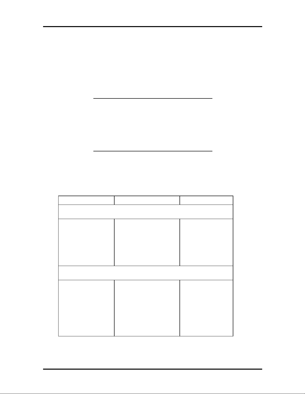
Table 1-1 PowerMate P2200M Minitower System
Configurations
Configurations Description
Non-multimedia 200-MHz Pentium MMX processor
3 1/2-inch diskette drive
2.0-GB hard disk
2 MB of SGRAM
16 MB of EDO RAM
256 KB secondary cache
Multimedia 200-MHz Pentium MMX processor
3 1/2-inch diskette drive
3.0-GB hard disk
Sixteen-speed CD-ROM reader
stem board w/audio
S
32 MB of EDO RAM
2 MB of SGRAM
256 KB secondar
20-watt speakers
Microphone
cache

Technical Information 1-2
y
y
y
y
Table 1-2 PowerMate P2166M System Configurations
Configurations Desktop Minitower
Non-multimedia 166-MHz Pentium MMX processor
3 1/2-inch diskette drive
2.0-GB hard disk
2 MB of SGRAM
16 MB of EDO RAM
256 KB secondary cache
Multimedia 166- or 200-MHz Pentium MMX
processor
3 1/2-inch diskette drive
3.0-GB hard disk
Sixteen-speed CD-ROM reader
stem board w/audio
S
32 MB of EDO RAM
2 MB of SGRAM
256 KB secondar
20 watt speakers
Microphone
cache
166-MHz Pentium MMX processor
3 1/2-inch diskette drive
2.0-GB hard disk
2 MB of SGRAM
16 MB of EDO RAM
256 KB secondary cache
166-MHz Pentium MMX processor
3 1/2-inch diskette drive
3.0 GB hard disk
Sixteen-speed CD-ROM reader
stem board w/audio
S
32 MB of EDO RAM
2 MB of SGRAM
256 KB secondar
20 watt speakers
Microphone
cache
Each system incorporates power management features and uses factory installed software to
enhance the hardware features. Systems come with the Windows® 95 operating system preinstalled (hot-loaded) on the hard disk.
The following paragraphs give an overview of the desktop and minitower systems.
Differences between systems are noted as they occur.
Technical Information 1-3
DESKTOP SYSTEM CHASSIS
The desktop chassis provides an enclosure for the system board, power supply, four
expansion slots, a five-connector PCI/ISA backboard, and four storage device slots. The
expansion slots include two 8-/16-bit ISA slots, one dedicated 32-bit PCI slot, and one
shared PCI/ISA (32-bit PCI or 8-/16-bit ISA) slot.
The four storage device slots accommodate up to three accessible devices and one internal
hard disk drive device. The accessible devices include the standard one-inch high 3 1/2-inch
1.44-MB diskette drive and up to two 1.6-inch high 5 1/4-inch storage devices. The nonmultimedia hard disk systems ship with an accessible 3 1/2-inch diskette drive and an
internal 3 1/2-inch hard disk drive, leaving two accessible 5 1/4-inch storage device slots
available for optional devices. The multimedia systems ship with an accessible 3 1/2-inch
diskette drive, an internal 3 1/2-inch hard disk drive, and an accessible 5 1/4-inch CD-ROM
reader, leaving one accessible 5 1/4-inch storage device slot available for an optional device.
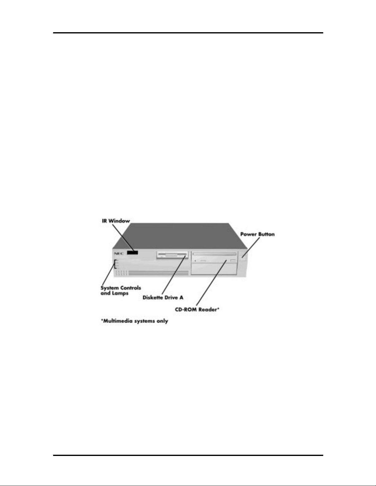
Figure 1-1 shows front panel features and locations of the accessible storage devices in a
desktop system. Multimedia systems come with a CD-ROM reader installed in the top
accessible device slot.
Figure 1-1 Desktop System Controls and Storage Device Slots
Technical Information 1-4
MINITOWER SYSTEM CHASSIS
The minitower chassis provides an enclosure for the system board, power supply, five
useable expansion slots, a six-connector PCI/ISA backboard, and six storage device slots.
The expansion slots include two 8-/16-bit ISA slots, one shared PCI/ISA slot, and two
32-bit PCI slots.
The six storage device slots accommodate up to four accessible devices and two internal
hard disk drive devices. The accessible devices include the standard one-inch high
3 1/2-inch 1.44-MB diskette drive and up to three 1.6-inch high 5 1/4-inch storage devices.
The non-multimedia hard disk systems ship with an accessible 3 1/2-inch diskette drive and
an internal 3 1/2-inch hard disk drive, leaving three accessible 5 1/4-inch storage device
slots and one internal slot available for an optional hard disk. The multimedia systems ship
with an accessible 3 1/2-inch diskette drive, an internal 3 1/2-inch hard disk drive, and an
accessible 5 1/4-inch CD-ROM reader, leaving two accessible 5 1/4-inch storage device
slots and one internal slot available for an optional hard disk.
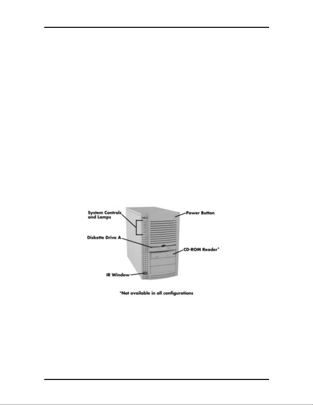
Figure 1-2 shows the front panel features and the locations of the accessible storage devices
in a minitower system. Multimedia systems come with a CD-ROM reader installed in the
top accessible device slot.
Figure 1-2 Minitower System Controls and Storage Device Slots

SYSTEM BOARD
Key features of the system board include the following:
Intel Pentium 166- or 200-MHz Pentium MMX processor, depending on system
configuration
32-KB internal dual write-back cache integrated on the processor (16 KB
instruction, 16 KB data)
256-KB of synchronous pipeline burst, secondary static random access memory
(SRAM) cache integrated on the system board
system Setup program built into the America Megatrends, Inc. (AMI) BIOS
flash ROM for fast economical BIOS upgrades
integrated input/output (I/O) controller with keyboard, diskette drive, and hard
disk drive controllers. Supports two serial ports, a parallel port, and an IrDA port.
PCI local bus for fast data transfer
Technical Information 1-5
PCI 2.1 compliant for concurrent real time input-output (I/O)
support for Intel OverDrive™ processors
32-bit, non-parity, 60-ns single-inline memory modules (SIMMs), expandable to
384 MB
16 MB (standard in PowerMate P MMX non-multimedia configurations)
32 MB (standard in PowerMate P MMX 3.0-gigabyte (GB) disk
configurations)
integrated graphics using ATI GT 64-bit PCI Graphics controller
2-MB SGRAM (1 MB on system board plus 1 MB on video module) expandable
to 4 MB with 3-MB video upgrade module
Creative Labs® Vibra 16C integrated sound (multimedia configurations only)
Sound Blaster and Roland MPU-401 UART compatible
Yamaha OPL FM synthesis
MPCII, Multimedia PC Level 2 and Adlib compliant
3D sound effects
plug and play

Technical Information 1-6
two intelligent drive electronics (IDE) interface channels, supports up to four IDE
devices; two on each channel
hard disk drive ships on the primary IDE channel, for optimum transfer rate
CD-ROM reader (some configurations) ships on secondary IDE channel (set
as master)
3 1/2-inch, 1.44-MB diskette drive standard all configurations
PCI/ISA backboard configurations
desktop provides four expansion slots: two ISA, one PCI, and one shared
ISA/PCI connectors
minitower provides five expansion slots: two ISA, two PCI, and one shared
ISA/PCI connectors
external connectors for connecting the following external devices:
VGA-compatible monitor (standard, super, high-resolution VGA)
personal system/2 (PS/2®)-style mouse (green connector)
PS/2-style keyboard (orange connector)
bidirectional Enhanced Parallel Port (EPP) and enhanced capabilities port
(ECP) are supported for a parallel printer
two 9-pin serial ports
two Universal Serial Bus (USB) ports
external speakers, microphone, and headphone connectors (multimedia
configurations only)

Technical Information 1-7
y
infrared (IR) window for wireless data transfers
hardware monitoring using an Heceta chip, monitors the following functions in
conjunction with LANDesk Client Manager software:
internal system temperature
chassis intrusion
power supply voltages
suspend button and power management for placing system in power save mode
when idle for a specified amount of time.
Table 1-3 lists the major chips on the system board. See Appendix A for system board
connector pin assignments. See Appendix B for a description of system board jumpers.
Table 1-3 System Board Chips
Chip Description
Intel P55C MMX 166/66-MHz or 200/66-MHz Intel Pentium
processor with MMX
Intel 82430HX PCI Chip Set
82439HX
82371SB
PC87306B
82557 (standard onl
configurations)
ATI GT-B1S2 (“B2”) Graphics controller
E28F002 256k x 8 Flash ROM
Real-Time Clock Coin Cell Battery 3 Volt Lithium CMOS battery (BT9A1)
Creative Labs Vibra 16C Sound Chip
(multimedia systems only)
Yamaha OPL3 FM Synthesizer Chip
(multimedia systems only)
in LAN
Xcelerator controller
PCI ISA/IDE controller
Ultra I/O controller
Local area network (LAN) controller in LAN
systems
Onboard PC sound system
Frequency modulated synthesizer

Technical Information 1-8
Processor
The PowerMate series of computers use the following Pentium processors:
PowerMate P2166M — 166-MHz MMX processor with internal speed of
166 MHz and external speed of 66 MHz.
PowerMate P2200M — 200-MHz MMX processor with internal speed of
200 MHz and external speed of 66 MHz.
Each processor has 32 KB of write-back primary cache and a math coprocessor. The 32 KB
primary cache provides 16 KB for instructions and 16 KB for data.
The processor is an advanced pipelined 32-bit addressing, 64-bit data processor designed to
optimize multitasking operating systems. The 64-bit registers and data paths support 64-bit
addresses and data types.
To use the Pentium processor’s power, the system features an optimized 64-bit memory
interface and complementary asynchronous pipelined 256-KB secondary cache.
The processor is compatible with 8-, 16-, and 32-bit software written for the Intel386™,
Intel486™, and Pentium processors.
To accommodate future technologies and work requirements, the Pentium processor comes
in a 320-pin zero insertion force (ZIF) socket. The socket provides an upgrade path to the
next generation processor.
Secondary Cache
The system board contains 256 KB of pipeline-burst, external to the processor. Cache
allows data to be sent or received from cache with one wait state burst. Cache memory
improves read performance by holding copies of code and data that are frequently requested
from the system memory by the processor. Cache memory is not considered part of the
expansion memory.

Technical Information 1-9
System and Video BIOS
The system and video BIOS are stored in a DMI-compliant, 2 MB (256K x 8) flash memory
device (Flash ROM). The system BIOS uses 64 KB and the video BIOS uses 32 KB. The
system BIOS is capable of being shadowed and cached through the system’s Setup utility
(see Section 2 for Setup information). System BIOS is write protected and automatically
enabled.
In addition to the system and video BIOS, the flash device contains the Setup Utility
program described in Section 2, Power-On Self-Tests, and Advanced Power Management
routines.
The BIOS programs execute the Power-On Self-Test, initialize processor controllers, and
interact with the display, diskette drives, hard disks, communication devices, and
peripherals. The Setup utility default copies the ROM BIOS into RAM (shadowing) for
maximum performance.
The Flash ROM allows the system and video BIOS to be upgraded with the BIOS Update
utility, without removing the ROM (see Section 2 for further information on the BIOS
Update utility). The Flash ROM supports the reprogramming of the system BIOS and the
video BIOS.
The system memory map is provided in Table 1-4.
Table 1-4 System Memory Map
Memory Space Size Function
00000-7FBFF 512K Conventional base memory
80000-9FBFF 127K Extended conventional
9FC00-9FFFF 1K Extended BIOS data
A0000-C7FFF 160K Video memory and BIOS
C8000-DFFFF 96K Available HI DOS memory (open to
ISA and PCI bus)
E0000-E7FFF 32K Post BIOS area
E8000-E8FFF 4K OEM Logo area or scan user flash
E9000-E9FFF 4K Reserved for BIOS
EA000-EBFFF 8K DMI configuration info (VPD ESCD)
EC000-EFFFF 16K Boot Block (available as UMB)
F0000-FFFFF 64K Main BIOS
100000-C000000 191M Extended memory

Technical Information 1-10
System Memory
Non-multimedia systems come standard with 16 MB of memory: 640 KB of base memory
and 15 MB of extended memory. Most other configurations come with a 2.0-GB hard disk
and 16 MB of memory: 640 KB of base memory and 15 MB of extended memory.
Multimedia configurations ship with a 3.0-GB hard disk drive and 32 MB of system
memory. System memory can be expanded up to 384 MB using optional single in-line
memory modules (SIMMs) installed in SIMM sockets on the system board.
Six SIMM sockets are integrated on the system board. Non-multimedia systems ship with
two 8-MB SIMMs (16 MB total) installed in two sockets. The 32-MB systems ship with
two 16-MB SIMMs installed.
The SIMM memory sockets accept 32-bit (non-parity) or 36-bit (parity) 4-, 8-, 16-, 32- or
64-MB 60 ns Extended Data Output (EDO) or Fast Page Mode (FPM) SIMMs. The
SIMMs are 1 MB x 32 bit (4 MB), 2 MB x 32 bit (8 MB), 4 MB x 32 bit (16 MB), 8 MB x
32 bit (32 MB), and 16 MB x 32 bit (64 MB). When the standard SIMMs are removed, six
64-MB SIMMs (FPM only – when available) may be installed for a total of 384 MB.
CAUTION:
SIMMs must match the tin metal
plating used on the system board SIMM sockets.
When adding SIMMs, use tin-plated SIMMs.
SIMMs install directly in the six sockets on the system board. The six sockets are assigned
as SIMM 1 through SIMM 6. Each pair of SIMM sockets are called banks. There are three
SIMM banks (labeled bank 0, 1, and 2). Systems ship with the two standard SIMMs
installed in SIMM sockets 1 and 2. SIMMs must be installed in pairs of the same memory
type. Jumpers are not required to set memory size or type as the system BIOS automatically
detects the SIMMs. See Section 3, “Option Installation” for the recommended SIMM
memory upgrade paths.
Integrated Graphics
The system has an ATI GT-B PCI 64-bit 3-D multimedia graphics and video controller
integrated on the system board. State of the art techniques are used for optimizing
performance in computer graphic intensive applications and graphical user interfaces (GUI).
Features include:
DDC rev 2b compliance
video acceleration and 3-D rendering
full screen Native video playback
2 MB of synchronous graphics random-access memory (SGRAM).
Technical Information 1-11
Video Memory
PowerMate P MMX systems come with 2 MB of on-board video SGRAM, upgradeable to
4 MB.
The first megabyte of SGRAM is mounted on the system board. Two connectors on the
system board accept a 1- or 3-MB video module, providing a total of 2 MB or 4 MB of
SGRAM.
NOTE: PowerMate P MMX systems have
1 MB of SGRAM on the system board and a
1 MB video module installed as standard
equipment. To upgrade from the standard 2 MB
to 4 MB, you must replace the standard 1 MB
video module with a 3 MB video upgrade
module.
Video Resolutions and Refresh Rates
The computer supports the following video resolutions and refresh rates under
Windows 95:
RESOLUTIONS SUPPORTED COLORS REFRESH RATE (HZ)
2 MB of video SGRAM (standard)
640 x 480
800 x 600
1024 x 768
1152 x 864
1280 x 1024
4 MB of video SGRAM (via 3-MB upgrade module)
640 x 480
800 x 600
1024 x 768
1152 x 864
16/256/16-bit/24-bit/32-bit
256/16-bit/24-bit/32-bit
256/16-bit
256/16-bit
256
16/256/16-bit/24-bit/32-bit
256/16-bit/24-bit/32-bit
256/16-bit/24-bit/32-bit
256/16-bit/24-bit/32-bit
120 Hz
120 Hz
120 Hz
120 Hz
85 Hz
120 Hz
120 Hz
100 Hz
80 Hz
1280 x 1024
1600 x 1200
256/16-bit/24-bit
256/16-bit
75 Hz
66 Hz

Technical Information 1-12
g
Interrupt Controller
The interrupt controller operates as an interrupt manager for the entire AT system
environment. The controller accepts requests from peripherals, issues interrupt requests to
the processor, resolves interrupt priorities, and provides vectors for the processor to
determine which interrupt routine to execute. The interrupt controller has priority
assignment modes that can be reconfigured at any time during system operations.
The interrupt levels are described in Table 1-5. Interrupt-level assignments 0 through 15 are
in order of decreasing priority. See Section 2, Setup and Operation, for information on
changing the interrupts using Setup.
Table 1-5 Interrupt Assignments
Interrupt
Priority
IRQ00 Counter/Timer
IRQ01 Keyboard
IRQ02 Cascade (INT output from slave)
IRQ03 COM2
IRQ04 COM1
IRQ05* Parallel Port 2/Audio (if present)
IRQ06 Diskette Drive Controller
IRQ07 Parallel Port 1
IRQ08 Real-time clock
IRQ09* Audio (if present)/Available
IRQ10* Available
IRQ11 ATI 3D Rage II/
Interrupt Device
IRQ Holder for PCI steerin
Intel 82371SB to USB Universal Host
Controller
/
IRQ12 PS/2 mouse
IRQ13 Coprocessor
IRQ14 Primary IDE
IRQ15 Secondary IDE
* Multimedia configurations use one of these interrupts.

Technical Information 1-13
I/O Addressing
The processor communicates with I/O devices by I/O mapping. The hexadecimal (hex)
addresses of I/O devices are listed in Table 1-6.
Table 1-6 I/O Address Map
Address (Hex) I/O Device Name
0000-000F DMA controller 1 (channel 0-3)
0020-0021 Interrupt controller 1
0040-0043 Timer 1
0048-004B Timer 2
0061 NMI status and control
0064 Keyboard controller byte
0070-007F Real-time clock, NMI mask
0080-008F DMA page registers
00A0-00A1 Interrupt controller 2
00C-00DE DMA controller 2
00E0-00EF Reserved
00F0 Clear math coprocessor error
00F1 Reset math coprocessor
0F8-0FF Math coprocessor
170-177 Secondary hard disk controller
1F0-1F7 Primary hard disk controller
200-207 Game I/O
220-22F Sound port
238-23F Serial port 4 (used for remapping)
278-27F Parallel port 2
2B0-2DF Alternate EGA adapter
2F8-2FF Serial port 2
338-33F Serial port 3 (used for remapping)
378-37F Parallel port 1
3B0-3BF Mono display and printer adapter
3C0-3CF EGA adapter
3D0-3DF CGA adapter
3F0-3F7 Primary diskette drive controller
3F8-3FF Serial port 1
CF8-CFF PCI configuration

Technical Information 1-14
ISA Bus
The system board uses the ISA bus for transferring data between the processor and I/O
peripherals and expansion boards. The ISA bus supports 16-bit data transfers and typically
operates at 8 MHz. ISA expansion slot connector pin assignments are provided in
Appendix A.
PCI Local Bus
The 32-bit PCI-bus is the primary I/O bus for the system. The PCI-bus is a highly-integrated
I/O interface that offers the highest performance local bus available for the Pentium
processor. The bus supports burst modes that send large chunks of data across the bus,
allowing fast displays of high-resolution images.
The PCI-bus operates at half the Pentium’s processor speed, and supports memory transfer
rates of up to 105 MB per second for reads and up to 120 MB per second for writes,
depending on processor configuration.
The high-bandwidth PCI-bus eliminates the data bottleneck found in traditional systems,
maintains maximum performance at high clock speeds, and provides a clear upgrade path to
future technologies.
The PCI bus contains two embedded PCI devices, the PCI local bus IDE interface and the
PCI video/graphics controller.
PCI expansion slot connector pin assignments are provided in Appendix A.
PCI Auto Configuration
The system comes with a PCI auto configuration utility that operates in conjunction with
the system’s Setup utility. The utilities automatically configure interrupts, DMA channels,
I/O space, and other parameters to allow addition of PCI boards with minimal user
intervention. (See Section 2 for Setup information.)
PCI/IDE Ports
The system board provides two high-performance PCI/IDE ports: a primary channel and a
secondary channel. Each port supports up to two devices for a total of four IDE devices.
The primary PCI/IDE port has an enhanced IDE interface which supports 11.1 MB per
second 32-bit wide data transfers on the high-performance PCI local bus. The installed hard
disk drive is connected to the primary PCI/IDE port. The installed CD-ROM reader
(multimedia and zip drive systems only) is connected to the secondary PCI/IDE port.

Technical Information 1-15
Parallel Interface
The system has a 25-pin parallel bidirectional enhanced parallel port on the system board.
Port specifications conform to the IBM-PC standards. The port supports Enhanced
Capabilities Port (ECP) and Enhanced Parallel Port (EPP) modes for devices that require
ECP or EPP protocols. The protocols allow high-speed bidirectional transfer over a parallel
port and increase parallel port functionality by supporting more devices.
The BIOS has automatic ISA printer port sensing. If the BIOS detects an ISA printer port
mapped to the same address, the built-in printer port is disabled. The BIOS also sets the
first parallel interface port it finds as LPT1 and the second port it finds as LPT2. The
interrupt is selected to either IRQ5 or IRQ7 via Setup. Software selectable base addresses
are 3BCh, 378h, and 278h.
I/O addresses and interrupts for the parallel port are given in Table 1-7.
NOTE:
parallel port are not available for ISA parallel
ports.
Any interrupts used for the built-in
Table 1-7 Parallel Port Addressing and Interrupts
Starting I/O Address Interrupt Level Port
378 IRQ05 LPT1
278 IRQ05 LPT1 or LPT2
3BC IRQ05 LPT1 or LPT2
378 IRQ07 LPT1
278 IRQ07 LPT1 or LPT2
3BC IRQ07 LPT1 or LPT2
Parallel interface signals are output through the system board’s 25-pin, D-subconnector.
The connector is located at the rear of the system unit. Pin locations for the parallel
interface connector are given in Appendix A.
Serial Interface
The system has two 16C550 UART compatible serial ports (COM1 and COM2) integrated
on the I/O controller. The serial ports support the standard RS-232C interface and the IrDA
interface (see Table 1-8). The buffered high-speed serial ports supports transfer rates up to
19.2 KB. These ports allow the installation of high-speed serial devices for faster data
transfer rates.

Technical Information 1-16
I/O addresses and interrupt levels for the two channels are given Table 1-8. The interrupt
level is selectable via Setup to either IRQ3 or IRQ4. Software selectable base addresses are
3F8h, 2F8h, 3E8h, and 2E8h.
NOTE: Any interrupts used for the built-in
serial ports are not available for ISA parallel
ports.
Table 1-8 Serial Port Addressing and Interrupts
Starting I/O Address Interrupt Level Port
3F8h IRQ04 COM1
2F8h IRQ03 COM2*
3E8h IRQ04 COM3
2E8h IRQ03 COM4
* Used for IrDA data transfer
Note that the COM2 port is factory set for IrDA data transfer and must be reset to
“Standard” for serial port transfers. See Section 2 for information on resetting the port
through the Setup Utility.
Serial interface specifications include:
Baud rate up to 19.2 KB per second
Word length - 5, 6, 7, or 8 bits
Stop bit - 1, 1.5, or 2 bits
Start bit - 1 bit
Parity bit - 1 bit (odd parity or even parity).
Serial interface signals are output through the system board’s 9-pin, D-subconnector. The
connectors are located at the rear of the system unit. Pin locations for the serial interface
connector are shown in Appendix A.
USB Interface
The Universal Serial Bus (USB) port allows you to add new plug and play serial devices
without opening up the system. You simply plug the devices into the port. The USB
determines system resources for each peripheral and assigns them without user intervention.
Up to 127 devices can be daisy chained to a single computer.

Technical Information 1-17
Infrared Interface
The I/O controller incorporates an infrared interface that provides two-way wireless
communication through the IrDA window (port) on the front of the system. The interface
uses infrared as the transmission medium instead of a traditional serial cable.
The IrDA port permits transfer of files to or from portable devices such as laptops and
personal digital assistant (PDA) products using the pre-installed LapLink applications
software or other software supporting IrDA data transfer. The port supports data transfers
at 115 Kbps from a distance of 1 meter (3 feet 3 inches).
The IrDA port uses the system’s COM2 serial port to transfer data. The port shares
registers and function logic with COM2.
POWER SUPPLY
The power supply is mounted inside the system unit. It supplies power to the system board,
option boards, diskette drives, hard disks, keyboard, and mouse. A fan inside the power
supply provides system ventilation. The power supply provides 200 watts. Connector
locations are in Appendix A.
DISKETTE DRIVE
Up to two diskette drives are supported in the desktop and minitower systems. The installed
3 1/2-inch diskette drive is connected by a single ribbon cable with two drive connectors.
The diskette drive cable plugs directly into the system board. Typically both diskette drives
are terminated. Connector locations are given in Appendix A.
HARD DISK DRIVE
Up to four IDE hard drives are supported in the desktop and minitower systems. The
system board has two IDE/PCI interface connectors (primary and secondary) for connecting
various storage devices such as hard disk drives. Each connector supports up to two IDE
devices.
Desktop hard disk systems ship with one internal 3 1/2-inch hard disk drive (1-inch high,
thin-height) installed behind the front panel. The drive cable plugs into the primary (fast)
connector on the system board.
Minitower hard disk systems ship with one internal 3 1/2-inch hard disk (1-inch high, thinheight) installed behind the front panel, at the bottom of the chassis. The three-connector
drive cable plugs into the primary (fast) connector on the system board. An optional second
hard drive can be connected to the cable and installed at the bottom of the minitower
chassis (see Section 3). Adding a third hard drive requires an optional two-drive connector
cable (NEC part number 158-050383-004). The optional cable plugs into the secondary
connector on the system board. If adding a fourth hard drive (in a 5 1/4-inch accessible
slot), it connects to the unused connector on the optional cable.

Technical Information 1-18
KEYBOARD
The PS/2-style 104 key keyboard is standard equipment for the system. The keyboard
provides a numeric keypad, separate cursor control keys, and 12 function keys, capable of
up to 48 functions. Status lamps on the keyboard indicate: Num (Numeric) Lock, Caps
(Capital) Lock, and Scroll Lock key status. The keyboard’s six-pin connector plugs into the
rear of the system. The keyboard connector pin assignments are given in Appendix A.
MOUSE
A PS/2-compatible mouse is standard equipment for the system. The mouse has a selfcleaning mechanism that prevents a buildup of dust or lint around the mouse ball and
tracking mechanism. The mouse’s six-pin connector plugs into the rear of the system. The
mouse connector pin assignments are given in Appendix A.
MULTIMEDIA COMPONENTS
Systems configured for multimedia come with audio integrated on the system board, a
CD-ROM reader, a speaker set, and a microphone. The following briefly describes each.
Information on setting up and operating the speakers, microphone, and CD-ROM reader is
in Section 2.
Integrated Audio
Multimedia systems come with audio components integrated on a Creative Labs Vibra 16C
single-chip VLSI mounted on the system board. Non-multimedia systems do not have the
audio components on the system board. The Vicra 16C provides all the digital audio and
analog mixing functions required for recording and playing audio on the computer. The
Vibra 16C integrates FM synthesis and provides Sound Blaster and Roland MPU-401
UART mode compatibility.
The integrated components also provide MPCII, Ad Lib™, and Multimedia PC Level 2
compliance for PC sound applications. The components work with the pre-installed audio
software (Voyetra®) and accomodate a variety of I/O addresses, DMA channels, and
interrupts (see Table 1-5 for interrupt assignments and Table 1-6 for the system I/O address
map).
The audio subsystem requires up to two DMA channels to support full duplex operation
and one interrupt.

Technical Information 1-19
CD-ROM Reader
A sixteen-speed IDE CD-ROM reader is pre-installed as drive F on multimedia
configurations. The reader can be used to load programs from a CD or it can be used to
play audio CDs. The reader operates at different speeds depending on whether the CD
contains music or data. This allows you to get your data faster and to see smoother
animation and video. The reader is fully compatible with Kodak Multisession Photo CDs™
and standard CDs. The reader is set as the master device on the secondary IDE/PCI
connector port.
NOTE:
CD-ROM with a bootable CD. To enable the
system to boot from the CD-ROM, see “Boot
Options” in Section 2.
You can boot the system from the
Speakers
PowerMate P2166M/P2200M Series multimedia models come with 20 watt high-quality
stereo speakers, an AC adapter, and connecting wires. The speaker set features a volume
control, power on/off button, power lamp, bass control, treble control, and a mini-stereo
headphone jack. Volume is controlled from the speaker or from the preinstalled sound
system software. The speaker set connects to the speaker line out jack on the back of the
system.
Microphone
The microphone that comes with the multimedia systems allows recording of voice and
sound into computer data files. The microphone connects to the MIC jack located on the
back of the system. The microphone works in conjunction with the audio software shipped
with the system.

Technical Information 1-20
PLUG AND PLAY
The system comes with a Plug and Play BIOS which supports Plug and Play technology.
Plug and Play eliminates complicated setup procedures for installing Plug and Play
expansion boards. With Plug and Play, adding a Plug and Play expansion board is done by
turning off the system, installing the board, and turning on the system. There are no jumpers
to set and no system resource conflicts to resolve. Plug and Play automatically configures
the board.
POWER MANAGEMENT
The BIOS supports Advanced Power Management (APM) features. The energy-saving
Stand-By mode can be initiated by a keyboard hot key sequence set by the user, a time-out
period set by the user, or by a suspend/resume button tied to the front panel sleep
connector.
While in Stand-By mode, the system board reduces power consumptiom utilizing the
Pentium processor’s System Management Mode (SMM) capabilities.The monitor goes
blank and the IDE hard drives spin down.
NOTE:
interrupts, such as network messages, is fully
maintained, allowing the system to service
requests while unattended.
Any keyboard or mouse activity brings the system out of energy-saving Stand-By mode (the
monitor and IDE drives are turned back on).
The system can be manually put into a Suspend energy-saving mode by pressing the
suspend button. A blinking power lamp indicates that the system is in the power-saving
mode. As soon as activity is detected, the system resumes where it left off.
APM is enabled in BIOS by default. APM parameters and features, such as the amount of
inactive time, are configurable through the Setup utility. See Section 2 for information on
setting power mangement parameters through Setup.
The system must be configured with an APM driver before the power saving features take
affect. Windows 95 enables APM automatically when it detects the presence of the APM
BIOS.
The ability to respond to external

Technical Information 1-21
LANDESK CLIENT MANAGER
LANDesk Client Manager is provided with your PowerMate system.
For installation procedures, see “LANDesk Client Manager Setup” and “Using LANDesk
Client Manager” in Section 2.
With Client Manager you can
review system inventory.
view DMI-compliant component information.
back up and restore system configuration files.
troubleshoot.
receive notice of system events.
transfer files to and from client workstations.
remotely reboot client workstations.
There are two main components of Client Manager: PC health indicator and inventory.
PC Health Indicator
PC health indicator consists of three parts:
Managing workstations
PC Health meter
PC health description.
Managing Workstations
Client Manager sets up a connection to all the workstations running on the network to
allow the administrator to monitor the functions of each workstation.
The monitoring is in real time so that if an unhealthy workstation is fixed, you can refresh
the screen to view the new correct PC health. You can also set the monitor to report only
unhealthy workstations.

Technical Information 1-22
PC Health Meter
The PC Health meter is a traffic signal that provides a visual indicator of workstation health.
A red light means that a critical system event has occurred. You are required to fix the
problem immediately.
A yellow light or noncritical system event requires that you monitor the situation. It may be
a problem that could get worse and become a critical event.
A green light means everything is working fine with the system.
PC Health Description
The description of PC health is determined by monitoring various system components for
threshold levels. Some of the components that are monitored include the following:
drive space
prediction of hard drive failure
free virtual memory
temperatures
power supplies
chassis opened
GDI
non-critical boot failure
boot virus detection.
Once a threshold level has been passed on a workstation, you can request notification of the
problem and have it written into a log file.

Technical Information 1-23
Inventory
Client Manager Inventory views the hardware and software components of your
workstation. The inventory consists of the following categories:
workstation summary
basic hardware
drives
memory
audio
keyboard/mouse
video
system resources
I/O ports
operating system
network
applications
system files
user information.
You can also view the current system configuration, edit user information, and create or
restore file snapshots.

Technical Information 1-24
Using DMI
As part of the LANDesk Client Manager, the Desktop Management Interface (DMI) is the
standard interface used to manage system components on the computer. Examples of
system components are software applications, network cards, and printers. System
components provide a Management Information Format (MIF) file to be DMI compliant.
The information file describes component attributes that can be managed.
Client Manager can be used to “get” attribute information on system components. It can
also be used to “set” attribute values in real time.
Heceta Capabilities
The computer has an Intel Heceta Head ASIC chip mounted on the system board. The
purpose of this chip is to provide real-time monitoring capabilities used by DMI. The
Heceta chip provides the following features:
an integrated temperature sensor with configurable interrupt generation based on
upper and lower temperature limits
a power supply monitor with configurable interrupt generation based on upper
and lower voltage limits
chassis intrusion detection with interrupt generation capabilities.
To take advantage of these features, DMI has expanded its interface in the following areas:
Heceta interrupts may be enabled or disabled.
High and low limits can be set and are displayed for temperature and power
supply voltages.
Current readings are displayed for temperature, power supply voltages, and
chassis state.
Heceta interrupts can be detected when “out of range” conditions occur. User
prompts are displayed to alert the user of a potentially harmful condition.

SPECIFICATIONS
g
g
g
g
g
g
g
g
System specifications are included in Table 1-9.
Table 1-9 Specifications
Item Specification
Technical Information 1-25
Dimensions and Weight
Desktop
Minitower Width: 8.5 inches (21.59 cm)
Keyboard Width: 19.0 inches (48.3 cm)
Device Slots
Desktop
Width: 17 inches (43.18 cm)
Depth: 16 inches (40.64 cm)
ht: 4 inches (10.16 cm)
Hei
Weight: 24.5 lb (11.03 kg) (dependent upon options)
Depth: 18.5 inches (46.99 cm)
ht: 14.5 inches (36.83 cm)
Hei
Weight: 20.5 lb (9.23 kg) (dependent upon options)
Depth: 8.4 inches (21.3 cm)
ht: 1.6 inches (4.1 cm)
Hei
Weight: 3.5 to 4.0 lb. (1.6 to 1.8 kg)
Three accessible slots:
— one 1-inch hi
standard 1.44-MB diskette drive)
— two 1.6-inch hi
CD-ROM reader in multimedia models)
One internal 1-inch hi
hard disk models);
h 3 1/2-inch front access slot (contains
h 5 1/4-inch slots (one contains standard
h 3 1/2-inch slot (contains hard disk in
Minitower Four accessible slots:
— one 1-inch hi
standard 1.44-MB diskette drive)
— three 1.6-inch hi
Two internal 3 1/2-inch slots (one contains a hard disk)
Expansion Slots
Desktop
Minitower
Four slots in the desktop, five in the minitower:
two 8-/16-bit ISA slots
one shared 8-/16-bit ISA/32-bit PCI slot
one 32-bit PCI slot
two 8-/16-bit ISA slots
one shared 8-/16-bit ISA/32-bit PCI slot
two 32-bit PCI slots
h 3 1/2-inch front access slot (contains
h 5 1/4-inch slots a CD-ROM reader)

Technical Information 1-26
y
g
y
y
y
g
y
g
y
Table 1-9 Specifications
Item Specification
Peripheral Interface PS/2-style 6-pin keyboard connector (mini DIN), rear panel
PS/2-st
Two RS-232C serial ports usin
Two USB ports, rear panel
Parallel printer port (25-pin), rear panel
VGA port (6-pin D-shell), rear panel
Front Panel Power button
Power indicator lamp
Hard disk drive bus
Suspend button
Reset button
le 6-pin mouse connector (mini DIN), rear panel
165550 UART, rear panel
indicator lamp
Microprocessor
Powermate P2166M
PowerMate P2200M
Cache Memory 16 KB of primary cache (8 KB data, 8 KB instruction) integrated
Flash ROM 128-KB (28F001) Flash ROM
Chip Set Intel 82430HX PCI Chip Set (see Table 1-3)
System Memor
Diskless Systems
Multimedia and Hard Disk
Systems
Optional SIMMs 4-, 8-, 16-, 32-; 64-MB 32-bit, non-parity, 60-ns or 70-ns SIMMs
Integrated Graphics ATI-based, DDC 2B compliant controller
Intel Pentium (processor type dependent on system)
166-MHz Pentium
200-MHz Pentium
in the processor, 256 KB secondar
board
16-MB standard, expandable to 384 MB usin
sockets on s
16- or 32-MB standard, expandable to 384 MB usin
SIMM sockets on system board and optional SIMM modules
PCI GUI Accelerator and Motion Video Pla
PCI-Bus Video
1- or 2 MB SGRAM standard
Maximum resolution 1280 x 1024 pixels
stem board and optional SIMM modules
cache built-in on system
72-pin SIMM
72-pin
back Controller
Battery Replaceable coin-type battery
Power Supply 200 Watt, 115 V/230V switch selectable
Input 100 V to 120 V – 5.0 A
Input 200 V to 240 V – 3.0 A
Output +12 V – 8 A
Output +5 V – 23 A
Output -12 V – 0.5 A
Output -12 V – 0.5 A

Table 1-9 Specifications
y
g
y
g
y
y
y
Item Specification
Technical Information 1-27
CD-ROM Reader
(multimedia systems only)
Integrated Sound Creative Labs Vibra 16C standard in multimedia systems
20-Watt Speakers Standard in multimedia models
Recommended Operatin
Environment
See Appendix D for specifications.
Stereo jacks for microphone in and line out
Sound Blaster compatible
nthesis
FM s
Ad Lib, MPC II, Multimedia PC Level 2 compliance
netically shielded 20-watt stereo speakers
Ma
Power on/off switch, power lamp, volume control
Treble and bass tone control
Built-in stereo amplifier
20W RMS power output
speaker system
2-wa
2-inch tweeter
4-inch woofer
Subwoofer output jack
External DC jack
Headphone jack
AC adapter
Dimensions
(28 cm) H
Temperature – 50°F to 95°F
Relative Humidity – 20% to 80%
120V to +15V,
5 in. (12.7cm) D x 4.5 in. (11.5 cm) W x 11 in.
−
15V
Administrative Compliance UL 1950 – safet
CSA C22.2 No. 950-m89
TUV EN60950: 1988
FCC part 15, Subpart J, Class B – emissions
FCC part 68
C.R.C., c.1374
Non-multimedia s
IEC 950 – safet
VDE 0871/6.78, Class B – emissions
stems are Energy Star compliant

Section 2
Setup and Operation
This section provides information on hardware setup and operation for the PowerMate
P2166M/P2200M series systems. Setup includes unpacking, setting up, and powering on
the system. It also includes information for configuring the system with the setup program,
using the NECCSD Bulletin Board Service, and running the BIOS update utility. Setting
system board jumpers is described in Appendix B, System Board Jumpers.
UNPACKING AND REPACKING
Find an area away from devices that generate magnetic fields (electric motors, transformers,
etc.). Place the carton on a sturdy surface, and carefully unpack the system. The carton
contents for non-multimedia configurations include the system unit, keyboard, mouse,
power cord, user documentation, and system recovery diskette. The carton contents for
multimedia configurations include the system unit with a CD-ROM reader, keyboard,
mouse, speakers, power cord, user documentation, CD-ROM disc with hotload backup, and
system recovery diskette.
Repack the system using the original shipping carton and packing material. Part numbers for
replacement shipping cartons and packing material are included in Section 4, Illustrated
Parts Breakdown.
SETUP
Connect the system components in accordance with one of the following subsections.
Desktop Configuration — for setting up desktop systems.
Minitower Configuration — for setting up minitower systems.
Desktop Setup
Set up the desktop system by making the following connections.
1.
Set the voltage selector switch to 115V (U.S. and Canada) or 230V and plug the
power cord into the system power socket (see Figure 2-1).

2-2 Setup and Operation
NOTE: The correct AC input voltage must be
properly set. Select the appropriate voltage with
the voltage selector switch located at the rear of
the system.
Figure 2-1 Desktop Voltage Selector Switch
Connect the keyboard, mouse, monitor, and printer cables to the back of the
2.
system unit (see Figure 2-2).
Figure 2-2 Desktop Peripheral Connections

Setup and Operation 2-3
If installing a multimedia system, connect the speakers as follows.
3.
Locate the right speaker (the controls are on the front) and the speaker cables.
Match and attached the color-coded speaker cables to the speakers.
Plug the speaker jack into the Line Out jack at the rear of the system (see
Figure 2-3).
Connect the AC adapter to the right speaker and to a surge protector or wall
outlet.
Press the power switch. The power lamp lights.
Adjust the volume control as required.
NOTE:
Headphones can be connected to the
jack in the front of the right speaker.
Plug the microphone into the microphone in jack at the rear of the system (see
4.
Figure 2-3).
Figure 2-3 Desktop Speaker and Microphone Jacks
Press the power button to power-on the system (see Figure 2-4). The power lamp
5.
lights green, indicating that the system is in Full-Power On mode.
The system automatically goes into its Power-On Self-Test (POST), and checks
system components. One beep indicates that the system has successfully
completed its power-on test.
If a problem occurs, a series of beeps may sound. If this happens repeatedly after
powering on, power off and troubleshoot the system (see Section 4 for
troubleshooting information.

2-4 Setup and Operation
Figure 2-4 Desktop Power Button, Lamps, and System Controls
To operate your speakers, turn on your system.
Push the power button on the front of the right speaker.
1.
Turn on your audio source.
2.
Adjust the volume by turning the volume control on the front of the right speaker.
3.
Adjust the bass and treble controls on the front of the right speaker to the desired
4.
levels.
Minitower Setup
Set up the minitower systems by making the following connections.
Set the voltage selector switch to 115V (U.S. and Canada) or 230V and plug the
1.
power cord into the power socket (see Figure 2-5).
NOTE:
properly set. Select the appropriate voltage with
the voltage selector switch located at the rear of
the system.
The correct AC input voltage must be

Setup and Operation 2-5
Figure 2-5 Minitower Voltage Selector Switch
Connect the keyboard, mouse, monitor, and printer cables to the back of the
2.
system unit (see Figure 2-6).
Figure 2-6 Minitower Peripheral Connections

2-6 Setup and Operation
If installing a multimedia system, connect the speakers as follows.
3.
Locate the right speaker (has the controls on the front) and the speaker cables.
Match and attached the color-coded speaker cables to the speakers.
Plug the speaker jack into the Line Out jack at the rear of the system (see
Figure 2-7).
Connect the AC adapter to the right speaker and to a surge protector or wall
outlet.
Press the power switch. The power lamp lights.
Adjust the volume control as required.
Plug the microphone into the microphone in jack at the rear of the system (see
4.
Figure 2-7).
Figure 2-7 Minitower Speaker and Microphone Jacks
Press the power button (see Figure 2-8) to power-on the system. The power lamp
5.
lights green, indicating that the system is in Full-Power mode.
The system automatically goes into its Power-On-Self-Test (POST) routine and
checks system components. One beep indicates that the system has successfully
completed its power-on test.
If a problem occurs, a series of beeps may sound. If this happens repeatedly after
powering on, power off the system.

Setup and Operation 2-7
If a problem occurs and is not indicated by beeps, power off the system and
Troubleshoot.
NOTE: If the system displays a message
indicating that system settings have changed, run
Setup (see “System Configuration” later in this
section). For troubleshooting information, see
Section 4.
Figure 2-8 Minitower Power Button, Lamps, and System Controls
POWER MANAGEMENT
Press the suspend button to place the unit into a power saving mode (see Figure 2-9 or
Figure 2-10). The system unit indicates that it is in a power saving mode when the power
lamp is blinking. Bring the system out of the power-saving mode by pressing the suspend
button again.
Figure 2-9 Buttons and Lamps - Desktop Model

2-8 Setup and Operation
Figure 2-10 Buttons and Lamps - Minitower Model
If the system is left alone for a preset time when power management is enabled in Setup (the
default time is 10 minutes), it goes into the automatic Standby mode. The screen goes blank
and the system goes into the power-saving mode of operation. Moving the mouse or
pressing a key places the system back in the Full-Power mode. See “System Configuration”
later in this section for information on using Setup.
NEC SETUP ICON
After the default Windows® 95 installation completes, double click on the NEC Setup icon.
This setup utility installs a custom NEC wallpaper, desktop icons, and applications that run
automatically when you start your NEC PowerMate system. Once the Setup process ends,
this icon no longer appears.
CD-ROM READER
A sixteen-speed CD-ROM reader (see Figure 2-11) comes pre-installed as drive F in the
multimedia configurations. The reader is set as a master device, and is connected to the
secondary IDE/PCI port on the system board.
NOTE:
system might look different than one shown in
the following figure. Some models do not have
the skip/play button. The locations of the other
features may vary but, the function are the same.
The CD-ROM reader installed in the

Setup and Operation 2-9
Use the CD-ROM reader to load and start programs from a CD or to play audio CDs. The
CD-ROM reader has the following controls and indicators:
jack for connecting headphones with a stereo mini-jack plug
volume control for adjusting the headphone volume
busy lamp that lights during read operations
open/close/stop button for opening or closing the CD tray when the power is on.
When playing a CD, press the open/close/stop button to stop the CD.
play/skip button to play a loaded CD. Press again to skip a selection. (This button
is not available on all CD-ROM readers.)
CD tray that opens and closes when the eject/retract button is pressed
emergency eject hole in the front panel for manually opening the CD tray if power
is lost. Insert a paper clip into the hole and press inward to open the tray.
Figure 2-11 Typical CD-ROM Reader Controls and Indicators
To load a disc in the CD-ROM reader, follow these steps.
Press the open/close/stop button. The CD tray opens.
1.
Put the CD, printed side up, into the tray.
2.
Press the open/close/stop button again and the tray closes.
3.
To remove the disc, press the open/close/stop button. The tray opens, allowing
4.
removal of the disc.

2-10 Setup and Operation
SYSTEM CONFIGURATION
This section describes the Setup utility program that allows the system configuration
information to be viewed and changed.
NOTE:
the correct system parameters for the
configuration. Unless setting the time and date,
setting security features, customizing the system,
or adding optional hardware, Setup does not
need to be run.
System configuration information is stored in nonvolatile memory. Nonvolatile memory in
the system is a complementary metal-oxide semiconductor (CMOS) chip backed by a
battery, either a coin-type battery or a real-time clock/battery module on the system board.
The battery supplies continuous power to the CMOS memory and maintains configuration
information when system power is off (see “Replacing the CMOS Battery” in Section 4).
The system ships from the factory with
Setup Utility
The Setup utility is used to view and set system parameters. Use the Setup utility to:
set the time and date.
update or check system parameters when adding or removing expansion options.
change or set power management features.
correct a hardware discrepancy when the Power-On-Self-Test (POST) displays an
error message and a prompt appears to run Setup.
check the installation of optional memory by comparing the amount of memory
installed with the amount of memory displayed by Setup.
change certain system operating parameters, such as boot device sequence or
keyboard parameters.
configure system connections for peripherals such as the diskette drive, hard
drives, and devices connected to the printer and serial ports.
customize the system with security features such as passwords, diskette drive
restriction, virus check reminder, and system backup reminder.
set system parameters if the CMOS battery or real-time clock/battery module
needs replacing.

How to Start Setup
To start the Setup utility, follow these steps:
Turn on or reboot the system.
1.
Press F1 after POST, but before the system boots up, to start the memory test.
2.
You have approximately five seconds to press F1 before the system boot
continues.
Setup’s Main Menu appears and looks similar to the following screen.
3.
Main Advanced Security Exit
System Date June 26 1996 F1 Help
System Time 08:12:20 ESC Back
Enter Select
Floppy Options Press Enter
Primary IDE Master IBM-DAQA-32160
Primary IDE Slave Not Installed
Secondary IDE Master Not-Installed
Secondary IDE Slave Not-Installed
Language English (US) F5 Setup Defaults
Boot Options Press Enter F6 Previous Values
F10 Save & Exit
Video Mode EGA/VGA
Mouse Installed
Base Memory 640
Extended Memory 15360
BIOS Version XX.XX
Setup and Operation 2-11
Previous Item
↑
Next Item
↓
Select Menu
←→
Figure 2-12 Main Menu

2-12 Setup and Operation
How to Use Setup
Use the keys shown on the right of the Setup menu to make your selections or exit the
current menu. The following table describes the navigation keys and their alternates.
Table 2-1 Navigation Keys
Key
F1 Provides help for the parameter
Esc Exits the menu.
Enter Executes Command or Selects
↓ or ↑ arrow
keys
← or → arrow
keys
F5 Loads the Default Configuration
F6 Selects the Previous Value for the
F10 Save and Exit
Function
field being displayed.
submenu.
Moves cursor up and down.
Selects next menu.
values for this menu.
field.
To display a submenu, use the arrow keys to move the cursor to the submenu you want.
Then press
Enter
.
Main Menu
The following is a list of available options when you select the Main Menu in the legend bar.
Other Main Menu options are available by selecting submenus.
NOTE:
typical Main menu screen.
Use the arrow keys to select one of the following Main Menu options and press
select a submenu. Items with grayed-out text are not available. Explanations of each menu
item follow.
System Date/Time
Diskette Drive
IDE Devices
See How to Start Setup for a look at a
Enter
to

Setup and Operation 2-13
Language
Boot Options
Video Mode
Mouse
Base Memory
Extended Memory
BIOS Version
System Date/Time
Use this menu to set the current time and date. The settings remain in memory even after
you turn off the system power.
To set the date, enter the current month, day, and year in mm/dd/yyyy format.
To set the time, enter the current hour, minute, and seconds in hh:mm:ss, 24-hour format.
For example, type
13:30:00
for 1:30 P.M.
Diskette Drive
This menu selects the type of diskette drive in your system. Unless you are changing your
hardware, you do not need to change the diskette drive (floppy) A or B settings.
If you add an optional 5 1/4-inch diskette drive to your system, select “Floppy B” and
change the parameter to “1.2 MB, 5.25 inch.”
IDE Devices
The hard disk drive (drive C:) shipped with some systems is configured as “Primary IDE
Master.” This field reports the presence of an identification string supported by, up to four
physical IDE drives (two on each PCI/IDE connector). If the cursor is placed on one of
these fields and the field is selected by pressing the
Enter
key, the IDE Device Submenu
appears. This submenu lets you set the drive parameters.
Jumper settings on the IDE device must be set to the master or slave device (see the
documentation that comes with the device).

2-14 Setup and Operation
IDE Device Configuration Submenu
The IDE Device Submenu lets you check or change the following hard disk drive
parameters.
IDE Device Configuration
Number of Cylinders
Number of Heads
Number of Sectors
Maximum Capacity
IDE Translation Mode
Multiple Sector Setting
Fast Programmed I/O Modes
IDE Device Configuration
The system is shipped with the default as “Auto Configured” selected in this submenu. The
system then automatically detects the hard disk type and sets the remaining parameters.
If your IDE hard disk does not feature auto IDE type detection or your IDE hard disk was
formatted on another system with parameters different than those reported by the drive, you
need to select “User Definable,” and set the “Number of Cylinders,” “Number of Heads,”
“Number of Sectors,” and “Maximum Capacity.”
IDE Translation Mode
The IDE Translation Mode parameter controls the way in which the BIOS interacts with
the drive in terms of drive geometry. Proper choice is dependent upon the drive’s size,
capabilities, and the operating system (OS) used. The following choices are available.
Standard CHS − is the translation mode that has been in use for years. Its use
limits IDE capacity to a maximum of 528 MB regardless of the size of the drive
used.
Logical Block − mode overcomes the 528 MB maximum size limitations imposed
by the Standard CHS mode. It should be used only when the drive supports
logical block addressing (LBA), and the OS supports LBA, or uses the BIOS to
access the disk.
Extended CHS − mode also overcomes the 528 MB maximum size limitations
imposed by the Standard CHS mode. It can be used with drives which are larger
than 528 MB, but do not support the LBA mode.

Setup and Operation 2-15
Auto Detected (default) − allows the BIOS to examine the drive and determine
the optimal mode. The first choice is to utilize Logical Block mode if it is
supported by the drive. The second choice is to utilize Extended CHS mode if the
drive topology allows. If neither of the above two methods are possible, then
Standard CHS mode is used.
CAUTION: When set to Auto Detected the
BIOS will detect what the drive is capable of, not
the translation mechanism which was used to
format the drive.
If a drive is run in a mode other than the mode in
which it was partitioned and formatted,
unpredictable results may occur, including data
loss.
Different OS’s have different abilities regarding IDE translation modes:
UNIX − does not currently support either LBA or ECHS and must utilize the
Standard CHS method. UNIX can support drives larger than 528 MB, but does
so in a different manner.
OS/2 2.1 and OS/2 WARP − can support LBA, ECHS, or Standard CHS
methods. Note that LBA support may require a switch setting on an OS/2 drive in
order to operate in the mode.
OS/2 2.0 and Novell Netware − can support either, ECHS or Standard CHS
methods, but not LBA.
DOS and Windows − can support LBA, ECHS, or Standard CHS methods. If the
“Fast 32-bit IDE” option of Windows is utilized, make sure to use the Standard
CHS setting only, unless a version of WDCDRV.386 is being used which
supports this advanced geometry.
You will get better performance not using “Fast 32-bit IDE” if using a drive which employs
Mode 3 PIO on the PCI interface, unless using a version of WDCDRV.386 which supports
these advanced modes.
Language
The installed language will appear in the Setup and BIOS text strings. English (US) is the
default in the U. S. and Canada.

2-16 Setup and Operation
Boot Options
When the cursor is placed in the Boot Option field, you can select it by pressing
Enter
. The
Boot Options Submenu appears allowing parameters which affect the boot process to be
set.
Boot Options Submenu
The Boot Options Submenu lets you check or change the following bootup parameters.
Boot Sequence
System Cache
Boot Speed
Num Lock
Setup Prompt
Hard Disk Pre-Delay
Typematic Rate Programming
Scan User Flash Area
Boot Virus Detection
Boot Sequence
The BIOS attempts to load the operating system in the sequence listed here. The defaults
are as follows.
First boot device − CD-ROM
Second boot device − Floppy
Third boot device − Hard Disk
Fourth boot device − Disabled
System Cache
The default for the System Cache field is “Enabled.” This field controls both the primary
and secondary caches. Setting the system cache to “Disabled” will hurt performance, but
might be required when running software which utilizes software timing loops and needs to
be slowed down to execute properly.
Boot Speed
Boot speed refers to the system CPU cycles. The default boot speed is “Turbo.” “De-turbo”
mode slows the CPU by disabling the system cache and adding increased refresh cycles.

Setup and Operation 2-17
NOTE: “De-turbo” does not reduce the CPU
speed to 8 MHz. If “De-turbo” is selected it will
automatically “Disable” the System Cache.
Num Lock
The Num Lock field controls whether the Num Lock key on the keyboard will be “On” or
“Off” at bootup. The default is “On.”
Setup Prompt
The Setup Prompt field allows you to disable the “Press <F1> Key To Enter Setup”
message displayed during POST. It does not control access, just the message. This field can
be either “Enabled” or “Disabled.” The default is “Enabled.”
Hard Disk Pre-Delay
The Hard Disk Pre-Delay field causes the BIOS to wait a specified time before accessing
the first hard disk drive. Setting a pre-delay provides the system with some time to identify
any additional drives before the standard hard drive initializes. The default is “Disabled.”
The delay times are as follows.
3 seconds
6 seconds
9 seconds
12 seconds
15 seconds
21 seconds
30 seconds
Disabled (default)
Typematic Rate Programming
The parameter controls whether the default user configuration values are used for
Typematic Rate Delay and Typematic Rate. The field is set as Default.
Default − sets the Typematic Delay to 250 msec and Typematic Rate to 15.
Override − provides the following two options. These options allow you to
customize the values.
Typematic Rate Delay
The Typematic Rate Delay field controls how long it takes for the keyboard auto-repeat
function to start when a keyboard key is held down. The delay times are as follows.

2-18 Setup and Operation
250 msec (default)
500 msec
750 msec
1000 msec
Typematic Rate
The Typematic Rate field controls the speed characters repeat when you hold down a
keyboard key. The higher the number the faster the repeat. The delay times are as follows:
6 char/sec (default)
8 char/sec
10 char/sec
12 char/sec
15 char/sec
20 char/sec
24 char/sec
30 char/sec.
Scan User Flash Area
Allows a user’s program to scan the user Flash area for user data. Can be set as “Disabled”
or “Enabled.” The default is “Disabled.”
Boot Virus Detection
Enables an anti-virus program resident in the BIOS to scan for any virus in the system. The
program can also repair the virus-infected area. The default is “Enabled.”
Video Mode
This field cannot be entered, it is an information field only. The system has a video
controller, the default is “EGA/VGA.”
Mouse
This field cannot be entered, it is an information field only. The system supports a PS/2
mouse. If the mouse is not installed the field will not be displayed. The default is “Installed.”

Setup and Operation 2-19
Base Memory
This field cannot be entered, it is an information field only. The system uses 640 KB of base
memory.
Extended Memory
This field cannot be entered, it is an information field only. Displays the amount of system
memory above 1 MB.
BIOS Version
This field cannot be entered, it is an information field only. Reports the BIOS identification
string.
Advanced Menu
Selecting “Advanced” from the menu bar on the Main Menu displays a menu with
the following options. Use the arrow keys to select an item from the Advanced
menu and press
Enter
. Explanations of each topic follow.
Processor Type
Processor Speed
Cache Size
Peripheral Configuration
Advanced Chipset Configuration
Power Management Configuration
Plug and Play Configuration
Event Logging Configuration
CAUTION:
Setting items in this menu to
incorrect values can cause your system to
malfunction.
Processor Type
This field cannot be entered, it is an information field only. The processor is a Pentium
processor that is backward compatible with 8086, 80286, I386, and Intel 486 processors.

2-20 Setup and Operation
Processor Speed
This field cannot be entered, it is an information field only. The processor operates at the
rated internal and external speeds.
Cache Size
This field cannot be entered, it is an information field only.
Peripheral Configuration
When the cursor is placed in the Peripheral Configuration field, you can select it by pressing
. The Peripheral Submenu appears for setting parameters that affect the IDE devices,
Enter
diskette drive, serial ports, and parallel port.
Peripheral Submenu
The Peripheral Submenu lets you check or change the following peripheral parameters.
IDE interface (primary and secondary
Floppy interface
Serial port (1 and 2) address
Serial port 2 IR mode
Parallel port address
Parallel port type
Audio interface
Hardware monitor interface
PCI LAN interface
IDE Interface (Primary and Secondary)
The Primary and Secondary IDE Interface fields enable the IDE interface connectors on the
system board. These fields can be either “Auto Configured” detected or “Disabled.” The
default is “Auto Configured.”
Floppy Interface
The Floppy Interface field enables the diskette drive interface connector on the system
board. This field can be either “Auto Configured” detected or “Disabled.” The default is
“Auto Configured.”

Setup and Operation 2-21
Serial Port (1 and 2) Address
The serial ports 1 and 2 may be “Auto Configured” detected or “Disabled.” The default is
“Auto Configured.” When “Auto Configured” is selected, the first free Serial port is
assigned regardless of what is selected.
The serial COM port and addresses are as follows. When an option is selected for one serial
port, the selection is not available for the second port.
Disabled
COM1, 3F8h, IRQ4
COM2, 2F8h, IRQ3
COM3, 3E8h, IRQ4
COM4, 2E8h, IRQ3
Serial Port 2 IR Mode
The Serial Port 2 IR Mode field allows you to dedicate Serial Port 2 for Infra-red
applications. This field can be either “Enabled” or “Disabled.” The default is “Enabled.”
Parallel Port Interface
The parallel ports may be “Auto” detected or “Disabled.” The default is “Auto.” When
“Auto” is selected, the first free LPT port is assigned regardless of what is selected. The
parallel port address options are as follows.
Disabled
LPT3, 3BCh, IRQ7
LPT1, 378h, IRQ7
LPT2, 278h, IRQ7
LPT3, 3BCh, IRQ5
LPT1, 378h, IRQ5
LPT 2, 278h, IRQ5
Auto
Parallel Port Type
The Parallel Port Type field options are as follows.
Compatible − sets the parallel port to the standard AT compatibility.
Bi-directional (default) − sets the parallel port to input/output mode only.

2-22 Setup and Operation
ECP − sets the parallel port to the Enhanced Capabilities Port (ECP) mode.
EPP − sets the parallel port to the Enhanced Parallel Port (EPP) mode.
Audio Interface
For multimedia systems, this option “Enables” the Vibra 16C audio subsystem. If this
option is “Disabled,” then the I/O resources and addresses that are used to support the
audio interface are freed. The default is “Enabled.”
Hardware Monitor Interface
This option “Enables” or “Disables” the hardware monitor subsystem. The default is
“Enabled.”
PCI LAN Interface
For network-ready systems, this option “Enables” or “Disables” the onboard LAN interface.
The default is “Enabled.”
Advanced Chipset Configuration
When the cursor is placed in the Advanced Chipset Configuration field, you can select it by
pressing
. The Advanced Chipset Submenu appears allowing parameters which affect
Enter
the system performance to be changed.
Advanced Chipset Submenu
The Advanced Chipset Submenu lets you check or change the following chipset parameters.
Base Memory Size
ISA LFB Size
ISA LFB Base Address
Video Palette Snoop
Latency Timer (PCI Clocks)
Banks 0, 1 and 2 SIMM Detected
Base Memory Size
The Base Memory Size field controls the mapping of addresses between “512 KB” and
“640 KB.” The two choices are described as follows.
512 KB − directs address mapping between 512 KB and 640 KB to the ISA bus.
640 KB (default) − directs address mapping between 512 KB and 640 KB to the
system DRAM. Unless using an ISA expansion board that requires access to this
address range, this field should not be changed.

Setup and Operation 2-23
ISA LFB Size
The ISA Video Linear Frame Buffer (LFB) Size provides a mechanism for creating a hole in
the system memory map. Address accesses made to this hole will be directed to the ISA bus
instead of main memory.
This “Disabled” setting should not be changed unless you are using an ISA board which has
memory greater than 64K, needs to be accessed by the CPU, and you are not using the Plug
and Play run-time utilities. The following choices are available.
Disabled (default)
1 MB
2 MB
4 MB
ISA LFB Base Address
This field cannot be entered, it is an information field only. If the ISA LFB field is
“Disabled,” this field does not appear.
The ISA Video LFB Base Address field displays “15 MB” (the starting address of the ISA
memory hole) if “1 MB” is chosen as the ISA LFB Size parameter.
Video Palette Snoop
The Video Palette Snoop field enables card “snoop” (also called RAMDAC shadowing)
write cycles to the ISA video card’s palette registers. This field can be either “Enabled” or
“Disabled,” the default is “Disabled.”
This should only be set to “Enabled” if all of the following conditions occur.
An ISA card connects to a PCI Graphics card via the VESA connector.
The ISA card connects to a color monitor.
The card uses the RAMDAC on the PCI card.
The palette snooping feature is broken on the PCI card.
Latency Timer (PCI Clock)
The Latency Timer (PCI CLOCK) field controls the length of time an agent on the PCI bus
can hold the bus when another agent has requested the bus. Value choices range between 0
and 256, the default value is 66.
Banks 0, 1 and 2 SIMM Detected
These fields cannot be entered, it is an information field only. These fields display either
“Fast Page Mode,” “EDO Mode,” or “None installed” depending upon what the BIOS
detects.

2-24 Setup and Operation
Power Management Configuration
Place the cursor in the Power Management Configuration field and select it by pressing
. The Power Management Submenu appears for setting parameters that affect the
Enter
power saving features.
Power Management Submenu
The Power Management Submenu lets you check or change the Advanced Power
Management parameter. Selecting the Advanced Power Management field enables or
disables power management support in the BIOS (the default is enabled).
Power management reduces the amount of energy used after specified periods of inactivity.
The Advanced Power Management menu offers you the choice of operating the system in a
full on state or standby state with partial power reduction when idle.
NOTE:
This field must be enabled to be Energy
Star Compliant.
Enabled (default) − allows the BIOS to work with the OS and reduce power
consumption when idle. This selection allows you to customize the following
power management fields.
Disabled − keeps the computer in a full on state and eliminates the following
power management options.
IDE Drive Power Down
The IDE Drive Power Down field controls whether or not a spin down command
will be issued to the IDE drives when the system goes into low power mode. This
field can be either “Enabled” or “Disabled.” The default is “Enabled.”
Inactivity Timer (Minutes)
The Inactivity Timer (Minutes) field controls the number of minutes that the
system will detect no user activity before going into low power mode. Minutes
range between 0 and 255; the default value is 10 minutes.
Hot Key
The Hot Key field is used to define a key which, when entered, will cause the
BIOS to put the OS into power management mode. Use this field to choose an
alphabetic character. Press
when not in Setup to use the feature. Typically, there is some delay before the
system enters power management mode and the speaker issues two tones.
CTRL
–
– user defined alphabetic character
ALT

Setup and Operation 2-25
y
y
y
y
y
y
y
If there is a User Password in effect the Num Lock, Caps Lock, and Scroll Lock
lamps on the keyboard flash in sequence, indicating that the system is in Secure
Mode. (See Set User Password field in Security Menu.)
In this case, the password has to be entered before you regain control of the
system. This password is not echoed to the screen. The following table describes
how the Powerdown Hot Key interacts with the Security Hot Key.
Table 2-2 Hot Key Parameters
Hot Key Function
Powerdown Hot Ke
Enabled Only
Security Hot Ke
Enabled Only
Both Hot Keys
Enabled
S
stem powers down. Powers up when
any key/mouse activity is detected.
S
stem secure immediately. Keyboard
lamps blink. Input accepted when
password typed.
System secure immediately. System
powers down. Ke
Input accepted when password t
Powers up when an
activity is detected.
board lamps blink.
ped.
key/mouse
Plug and Play Configuration
When the cursor is placed in the Plug and Play Configuration field, you can select it by
pressing
. The Plug and Play Submenu appears for setting PCI/ISA Plug and Play
Enter
expansion board parameters.
Plug and Play Submenu
The Plug and Play Submenu lets you check or change the Configuration Mode parameters.
Use the Configuration Mode field to choose the method on how the BIOS gets information
about ISA expansion boards that do not have Plug and Play capabilities. This allows the
BIOS to set up PCI and ISA Plug and Play expansion boards without conflicting with nonPlug and Play ISA boards.
The choices are as follows.
Use BIOS Setup − The BIOS depends upon the information provided by run-time
Plug and Play software (Configuration Managers and ICU). When “Use BIOS
Setup” is chosen, the BIOS depends on run-time software to ensure that there are
no conflicts between ISA boards with Plug and Play capabilities and those
without.

2-26 Setup and Operation
Use PnP OS (default) − If “Use PnP OS” is selected, the BIOS depends on run-
time software to ensure that there are no conflicts between ISA boards with Plug
and Play capabilities and those without. Only “Boot With PnP OS” is visible.
Boot with PnP OS
The Boot with PnP OS field enables the system to boot with an operating system
capable of managing Plug and Play add-in cards. The choices are as follows.
None
Other
Windows95 (default)
ISA Shared Memory Size
The ISA Shared Memory Size field is used to set a block of system memory which
will not be shadowed. (Shadowing is a technique which copies a block of memory
from an address in the expansion board’s ROM to the same address in the system
memory to allow faster access to the code and achieve higher performance.)
If “Disabled,” all upper memory is shadowed and ISA Shared Memory Base
Address field is not displayed. This field provides the following choices.
When a value other than “Disabled” is selected, a block is unshadowed and the
ISA Shared Memory Base Address field will appear.
Disabled (default)
16 KB
32 KB
48 KB
64 KB
80 KB
96 KB
NOTE: If a value of “96 KB” is selected, then
the ISA Shared Memory Base Address field can
only be set to C8000h; if “80 KB,” then a value
of C8000 or CC000h, etc.

ISA Shared Memory Base Address
The ISA Shared Memory Base Address field is only displayed when an ISA
Shared Memory Size has be selected. The choices are as follows.
C8000h (default)
CC000h
D0000h
D4000h
D8000h
DC000h
Available interrupt requests (IRQ) between IRQ3 through IRQ15 will be
displayed. Interrupts consumed by on-board resources will not be visible.
NOTE: All but one IRQ can be set to “Used By
ISA Card.” One must remain available for a PCI
expansion board.
Setup and Operation 2-27
Event Logging Configuration
When set to Enabled, keeps track of system events.

2-28 Setup and Operation
Security Menu
There are two types of passwords available: “User Password” and “Administrative
Password.” The user passwords can be used to access the Setup Utility, the keyboard upon
initial boot and the keyboard when used in conjunction with the Security Hot Key. The
Administrative Password is used to control access to the Setup Utility. The following table
describes the interaction between these passwords.
Table 2-3 Security Passwords
Password
Enabled
User
Password
Only
Administrative
Password
Only
Both User and
Administrative
Passwords
No Passwords
Enabled
Password at
Boot
Yes No Yes Yes Yes
No Yes Yes No No
Yes No No (User)
No No Yes No No
Access
Setup
Access All
Setup Fields
Yes (Admin)
Set Unattended Start
Yes Yes
Set Security
Hot Key
If the Administrative Password is in effect and Setup is entered with the User Password,
only the following fields may be changed.
System Date
System Time
User Password
Security Hot Key
Unattended Start
Power Management Hot Key
NOTE:
You can enter the Setup program with
either a User or Supervisor password. However,
more Setup choices are available with the
Supervisor password.
The Security Submenu lets you check or change the following password parameters.

Setup and Operation 2-29
NOTE: If neither the User or Administrative
Password is “Enabled,” the Unattended Start and
Security Hot Key fields are not displayed.
User Password
This field allows you to enable a user level password during POST and to enter
Setup. When both the “User Password” and “Administrative Password” are
“Enabled,” only the Administrative Password gives you full access to all Setup
fields. This field can be either “Enabled” or “Disabled.” The default is “Disabled.”
Administrative Password
This field allows you to enable an administrative level password during POST and
to enter Setup. When both the “User Password” and “Administrative Password”
are “Enabled,” only the Administrative Password gives you full access to all Setup
fields. This field can be either “Enabled” or “Disabled.” The default is “Disabled.”
Set User Password and Set Administrative Password
Enable either or both the User or Administrative Passwords and a dialog box with the
following prompts appears. Passwords are not case sensitive.
To set a password, type the password and press
password and press
Enter new password: [ ]
Confirm new password: [ ]
Enter
.
. Reenter your
Enter
If there is already a User or Administrative Password, then a dialog box with the following
prompts appears.
Enter current password: [ ]
Enter new password: [ ]
Confirm new password: [ ]
Unattended Start
The Unattended Start field controls the point at which the User Password is required. The
Unattended Start field can only be set if a User Password is in effect.
Disabled (default) − prompts the user for the password before the system boots. The text
string prompt “Enter Password (1).” is displayed.
Enabled − completely boots the system (including running CONFIG.SYS and
AUTOEXEC.BAT), then locks the keyboard. The User Password must be entered to
unlock it. The BIOS does not provide any prompt string.

2-30 Setup and Operation
Security Hot Key (CTRL-ALT-)
The Security Hot Key field is used to lock the keyboard when you step away from the
system. When you press
CTRL
–
– alpha-numeric key (the alpha-numeric key is
ALT
defined by the user) the system enters secure mode (locks the keyboard).
When this Hot Key combination is entered the Num Lock, Caps Lock, and Scroll Lock
lamps on the keyboard will flash in sequence, indicating that the system is in secure mode.
Exit Menu
Selecting “Exit” from the menu bar displays the following exit options. Click on a topic for
a description of the Exit Menu options. Note that
select one of the items from the menu or menu bar to exit.
Exit Saving Changes
Exit Discarding Changes
Esc
does not exit this menu. You must
Load Setup Defaults
Discard Changes.
Exit Saving Changes
After making your selections on the Setup menus, always select “Exit Saving Changes” to
make them operative.
When “Exit Saving Changes,” has been selected, the program displays this message:
Exit Saving Changes?
Press Enter to Continue
Press ESC to Abort
To save the changes and exit Setup press
Enter
. Press
Esc
to return to the Exit submenu
without affecting your changes.
Exit Discarding Changes
Use this option to exit Setup without recording any changes you may have made. After you
select “Exit Discarding Changes, the program displays this message:
Exit Discarding Changes?
Press Enter to Continue
Press ESC to Abort
To exit Setup without saving the changes press
submenu without affecting your changes.
Enter
. Press
Esc
to return to the Exit

Setup and Operation 2-31
Load Setup Defaults
To load all the default Setup values in the Setup menus, select “Load Setup Defaults” from
the Exit Submenu. Reloading the defaults does not affect the any set passwords. The
program displays this message:
Load Setup Defaults?
Press Enter to Continue
Press ESC to Abort
To load the defaults shipped with the system press
Enter
. Press
to return to the Exit
Esc
submenu without affecting your changes.
Discard Changes
To undo any changes you have made in the Setup menus since Setup was last saved, select
“Discard Changes.” The program displays this message:
Discard Changes?
Press Enter to Continue
Press ESC to Abort
To reset all changes made in the current session of Setup, press
Enter
. Press
Esc
to return
to the Exit submenu without affecting your changes.
BIOS UPDATE UTILITY
The system BIOS resides on a flash ROM in the system. The flash ROM can be updated,
should it ever become necessary. This feature allows the ROM BIOS chip to be flashed with
a new BIOS code through software, rather than replacing the chip.
Performing an update is done with a BIOS flash diskette. The diskette, which contains the
latest version of the BIOS code, can be obtained from NEC Computer Systems Division or,
if a modem is available, the latest BIOS can be downloaded from NECCSD’s Bulletin
Board Service (BBS).
If a modem is available, use the following procedure to access the BBS for the latest
version of the BIOS Update utility. How to flash the BIOS with a flash diskette is described
following the BBS access procedure.
NECCSD Bulletin Board Service
If you have access to a modem, the NECCSD Bulletin Board Service (BBS) can be used to
provide you with the latest information on hardware and software. The BBS allows you to
download files (video drivers, printer drivers, BIOS updates, etc.) for system enhancements
and upgrades.
The BBS can also be accessed through the CompuServe online service.

2-32 Setup and Operation
Log onto the BBS as follows.
From the Windows 95 desktop, click the Start button.
1.
Point to Programs. Point to Accessories and then click HyperTerminal.
2.
Double click the Hypertrm.exe icon. The HyperTerminal program appears.
3.
Follow the instructions on the screen to set up your modem. Click the
4.
HyperTerminal Help button for information about dialing the phone number.
If you need to check communications settings, check that the settings match the
following BBS parameters.
Baud rate: select any baud rate that matches your modem
Parity: none
Data bits: 8
Stop bits: 1
Flow control: Xon/Xoff (select Hardware if using 14.4 bps or higher)
Following the HyperTerminal instructions, enter the BBS phone number (508-
5.
635-4706). Your business phone system and/or location might require a 9 1 or 1
prefix.
NOTE:
The first time that you use the BBS,
you will be requested to provide information for
a new user questionnaire.
Press
6.
Enter your first name, last name, and password. Press
7.
Follow the screen prompts until the Main Menu is displayed.
8.
At the Main Menu, select J to join a conference. Select
9.
Enter
twice
after each.
Enter
Conference 1
for the
desktop conference.
From the Main Menu, press F and
10.
At the File menu, select F for a list of downloadable files. Follow the prompts to
11.
for the File menu.
Enter
select a file for downloading.

Setup and Operation 2-33
CAUTION: Executable files automatically
format your diskette when you download files
from the BBS. Formatting destroys any data on
the diskette. Before you download files from the
BBS, check that you do not have information on
the diskette that you need.
After you complete downloading your file, log off the BBS as follows.
Press
1.
Press G (command for Goodbye/Hangup).
2.
Press
3.
Enter
Enter
.
(to continue)
Using the BIOS Update Utility
Update the BIOS from the BIOS flash diskette as follows.
Write down the Setup parameters currently set on the system.
1.
Turn off the system.
2.
Insert the flash diskette in drive A, and turn on the system.
3.
The update procedes automatically and shows a BIOS Update successfully
4.
completed message when done.
Press any key to reboot the system.
5.
Remove the flash diskette.
6.
CD RESTORE
Your system ships with a CD Restore compact disc (CD) included. The CD Restore files let
you restore all your system software files to their original factory-installed state.
The following subsections contain information on:
selecting CD Restore options
restoring individual files
recovering your system.
Selecting CD Restore Options
The following guidelines should help you decide which CD Restore procedures you should
use.

2-34 Setup and Operation
Restore Individual Files
This option lets you select the files and directories you want restored from the CD Restore
compact disc. Use this option to:
restore only a few files
control which files and directories are restored to their factory state.
You can use this option for restoring AUTOEXEC, CONFIG, and INI files.
This procedure runs in Windows 95. You’ll need to boot the system from the hard disk,
enter Windows, and insert the CD into the CD-ROM reader.
System Recovery
Use this option as a last resort when your preinstalled software becomes unusable or you
can’t reboot from the hard disk. This option requires booting from the CD.
The System Recovery option
provides a full system recovery. This means you’ll be able to restore your system
to its original factory-shipped state.
reformats hard drive C and erases all information on the disk.
then restores files on drive C from the CD Restore disc.
Before System Recovery, you will need to
back up all your data files to an external storage device (diskette, tape, or Zip
cartridge drive). System Recovery removes all data.
be prepared with software installation diskettes of any software application
programs that you installed yourself.
After System Recovery, you will need to
restore to the hard disk all the data files that you backed up before System
Recovery.
reinstall any software application program that you installed yourself.
The following sections describe each of these options. If your preinstalled software becomes
unusable, see “Recovery Options” later in this section.

Restoring Individual Files
Here’s how to restore individual files to your hard disk:
1.
With system power on, insert the CD Restore disc into the CD-ROM reader.
2.
On the Windows 95 desktop, double click “My Computer.”
3.
Double click the CD-ROM reader “(F:)” icon. The NEC System Restore screen
appears.
4.
At the System Restore screen, click “OK” to restore individual files. A license
agreement appears.
5.
Read the license agreement and click “I agree” to continue. The Restore
Individual Files screen appears. The screen is divided into two areas:
1 Select files to restore — This is where you select
the specific files you want to restore.
Setup and Operation 2-35
2 Check list of files to be restored — This area lets
you check the files you selected for restoration.
The following sections explain how to use the Restore Individual Files screen. Complete all
sections to restore your files.
Selecting Files
Under “Select files to restore,” select your files as follows:
1.
From the left dialog box, highlight the directory that contains the files you want to
restore.
2.
From the right dialog box, highlight the files you want to use:
To restore all of the files listed, click “Select all of the above.” This highlights
and selects all the files listed.
To restore only some of the files listed, click the file you want and highlight it.
3.
Once your files are highlighted, select the appropriate button under the list. The
buttons include:
Add selected files to list — click this button to add the selected files to the list
of files to be restored.
Clear all selections — click this button to deselect the files listed.
4.
Repeat steps 1 through 3 to select files from other directories. Continue until all
the files you want restored are selected.

2-36 Setup and Operation
Checking Selected Files
To continue the restoration process, check the files to be restored as follows.
Look at the list of files in the “Check list of files to be restored” area of the
1.
screen.
If you need to add any files to the list, go back to the preceding section and repeat
2.
those steps.
If you need to remove any files from the list, do so as follows.
3.
To remove any selected files, highlight the file name and click “Delete item in
list.” This method lets you remove one item at a time.
To remove the entire list, click “Clear list.”
Once the list is set, continue to the next section.
Restoring the Files
Complete the restoration process as follows.
In the “Restore the files from the CD” area of the screen, locate the two options:
1.
Restore the files listed — this option lets you proceed with the restoration and
continue to the next step. Go to the next step to complete the restoration.
Cancel — click this option to cancel the restoration. This returns you to the
NEC System Restore menu.
To proceed with the restoration, click “Restore the files listed.” When the
2.
restoration is completed, a file restore message appears.
.
OK
Click
3.
If you replaced any Windows system files, exit Windows and restart the system.
4.
Recovering the System
If the preinstalled software becomes unusable or you can’t reboot from the hard disk, you
can restore your system to its original shipping configuration.

Setup and Operation 2-37
System Recovery erases and resets the hard disk completely before reinstalling the files.
CAUTION: If you are doing a Full System
Recovery, ALL files on the hard drive will be
deleted and replaced by the factory installed files.
You will
lose data
need to reinstall any software you installed
yourself.
Full System Recovery should only be used if
the preinstalled software is unusable. If you
are unsure about using this procedure, call the
NECCSD Technical Support Center (TSC).
TSC representatives will help you determine
if this is your situation. See Section 4 for the
technical support telephone number.
The System Recovery requires booting from the CD Restore disc. Here is the procedure to
start the recovery process. Follow it carefully.
With system power on, insert the CD Restore disc into the CD-ROM reader.
1.
Turn system power off.
2.
Turn on system power. The System Recovery screen provides information about
3.
the restore process. Read this information.
You can choose one of the following two options:
Continue — Proceeds with the recovery program.
Quit — Exits the recovery program back to the operating system.
Click “Continue” to proceed with the System Recovery. A license agreement
4.
appears.
Read the license agreement and click “I agree” to continue. The Start System
5.
Recovery screen appears.
The Start System Recovery screen states that all the files will be removed and that
6.
this process is irreversible. At the “Are you sure?” prompt, click “Yes” to
continue.

2-38 Setup and Operation
The system files are restored and the System Recovery Completed screen appears. Remove the
CD and restart your computer.
LANDESK CLIENT MANAGER SETUP
Use the following procedure to setup the LANDesk Client Manager software.
1.
Click the Start button on the taskbar.
2.
Point to “Programs” to open the Programs menu.
3.
Point to “NEC Information Center” and click on “LANDesk Client Manager
Setup.”
4.
Follow the instructions in the Setup program.
Using LANDesk Client Manager
Refer to the following subsections for known LANDesk Client issues.
Accessing the LANDesk Client Online Guide
The LANDesk Client features an extensive Read me document. Use the following steps to
access the guide.
1.
Click the Start button and point to “Programs.”
2.
In the Programs list, point to “LANDesk.” Then select “LANDesk 3.0 Readme.”
“Discover” Feature
The Discover feature has inconsistent behavior. For best performance, use the following
steps.
1.
In the Select Workstation dialog box, select the local system. This closes the
Select Workstation dialog box.
2.
From the File menu, access “Select Workstation”. This refreshes the dialog box
listing.
You can now select any workstation as needed.

Setup and Operation 2-39
Heavy Network Use with Other PowerMate Models
When LANDesk Client Manager Admin tries to select a remote client such as a PowerMate
model with LANDesk Client Manager client software installed during heavy network load,
LANDesk Client Manager Admin might display the following message:
The remote workstation is not responding to the requests, please select another
workstation.
If the remote workstation is the PowerMate P2166M/P2200M Series model, use the
PROSET utility program shipped with the Intel EtherExpress driver to configure the
onboard Intel EtherExpress 10/100 to be (a) 10 MBPS and (b) half duplex.
These settings can also be made from the network dialog in the Windows Control Panel or
from the network neighborhood properties dialog.
Multiple Admin Sessions
Do not use multiple Admin sessions within one physical network environment. Many
remote clients attributes will be incorrect if multiple sessions occur.
Audio Not Listed in DMI
The DMI Audio listing does not list the audio features in the PowerMate P2166M/P2200M
Series system.

Section 3
Option Installation
This section provides instructions for installing the following options:
expansion boards
SIMM memory upgrade
video memory upgrade
processor upgrade
data storage devices
external options.
All options require that the system cover be removed. Procedures for removing the desktop
and minitower covers are included in this section.
GENERAL RULES FOR INSTALLING OPTIONS
Follow these general rules when installing system options.
Turn off system power and unplug the power cable.
Turn off and disconnect all peripherals.
When handling boards or chips, touch the system unit frame to discharge static.
Do not disassemble parts other than those specified in the procedure.
All screws are Phillips-head, unless otherwise specified.
Label any removed connectors. Note where the connector goes and in what
position it was installed.
PRECAUTIONS
Take care when working inside the system and when handling computer components. Avoid
electric shock or personal injury by observing the following warning.

3-2 Option Installation
WARNING: Before removing the system unit
cover, turn off the power and unplug the system
power cable. Power is removed only when the
power cable is unplugged.
Static electricity and improper installation procedures can damage computer components.
Protect computer components by following these safety instructions.
CAUTION: Electrostatic discharge can damage
computer components. Discharge static
electricity by touching a metal object before
removing the system unit cover.
Avoid carpets in cool, dry areas. Leave an option, such as a board or chip, in its
anti-static packaging until ready to install it.
Dissipate static electricity before handling any system components (boards, chips,
and so on) by touching a grounded metal object, such as the system’s unpainted
metal chassis.
If possible, use anti-static devices, such as wrist straps and floor mats.
Always hold a chip or board by its edges. Avoid touching the components on the
chip or board.
Take care when connecting or disconnecting cables. A damaged cable can cause a
short in the electrical circuit. Misaligned connector pins can cause damage to
system components at power-on.
When installing a cable, route the cable so it is not pinched by other components
and is out of the path of the system unit cover. Prevent damage to the connectors
by aligning connector pins before you connect the cable.
When disconnecting a cable, always pull on the cable connector or strain-relief
loop, not on the cable.
REMOVING AND REPLACING THE SYSTEM UNIT COVER
The following subsections describe how to remove the system unit cover from the desktop
and minitower systems.

Removing the Desktop Cover
WARNING:
cover, turn off the power and unplug the system
power cable. Power is removed only when the
power cable is unplugged.
1.
Turn off and unplug the system unit.
2.
Disconnect the keyboard, mouse, monitor, and any other external options (such as
a printer) from the rear of the system unit.
CAUTION:
computer components. Discharge static
electricity by touching a metal object before
removing the system unit cover.
Before removing the system unit
Electrostatic discharge can damage
Option Installation 3-3
3.
Loosen the two captive thumb screws at the rear of the system unit.
Figure 3-1 Removing Cover Screws
4.
From the rear of the system, grasp the sides and slide the cover about an inch
away from the front.
NOTE:
The cover fits tightly. Press the front
edge of the cover to release it from the front
panel. Also press against the rear panel to slide
the cover one inch away from the front panel.

3-4 Option Installation
Figure 3-2 Releasing the Cover
Lift the cover up and away from the system unit.
5.
Replacing the Desktop Cover
Replace the cover as follows.
Align the tabs on the sides of the cover with the inside unit frame as you position
1.
the cover over the chassis (see Figure 3-3).
Figure 3-3 Replacing the System Unit Cover
Slide the cover forward to meet the front panel.
2.

Option Installation 3-5
NOTE: The cover fits tightly. If the cover does
not slide all the way to the front panel, place one
hand on the front of the unit while you slide the
cover forward from the rear.
Secure the cover with the two thumb screws. (See “Removing the Desktop
3.
Cover,” earlier in this section.)
Reconnect all external peripherals.
4.
Plug in your power cables.
5.
Removing the Minitower Cover
The following procedure describes how to remove the minitower cover.
WARNING: Before removing the system unit
cover, turn off the power and unplug the system
power cable. Power is removed only when the
power cable is unplugged.
Turn off and unplug the system unit.
1.
Disconnect the keyboard, mouse, monitor, and any other external options (such as
2.
a printer) from the rear of the system unit.
CAUTION: Electrostatic discharge can damage
computer components. Discharge static
electricity by touching a metal object before
removing the system unit cover.
Loosen the three thumb screws at the rear of the system unit.
3.

3-6 Option Installation
Figure 3-4 Loosening Minitower Cover Screws
From the rear of the system, grasp the handle and pull it back so that the cover
4.
clears the padlock slot.
Figure 3-5 Releasing the Minitower Cover
Lift up at the top of the cover to release the cover tabs from the chassis.
5.
Pull the cover up until it comes free of the chassis.
6.
Replacing the Minitower Cover
Replace the minitower cover as follows.

Option Installation 3-7
Insert the metal tabs on the top of the system cover into their slots on the chassis.
1.
Insert the metal tabs on the bottom of the system cover into their slots on the
2.
chassis.
Figure 3-6 Replacing the Minitower Cover
Slide the cover forward to meet the front panel.
3.
NOTE:
not slide all the way to the front panel, place one
hand on the front of the unit while you slide the
cover forward from the rear.
Secure the cover with the three thumb screws. (See “Removing the Minitower
4.
Cover” earlier in this section.”)
Reconnect all external peripherals.
5.
Plug in your power cables.
6.
Expansion Boards
The cover fits tightly. If the cover does
The computer supports ISA Plug and Play expansion boards. Plug and Play expansion
boards allow installing a board in an expansion slot without changing the hardware settings.
There are no system resource conflicts to resolve. Plug and Play automatically configures
the board for the system.
Industry-standard 8- 16-bit, ISA and 32-bit PCI expansion boards are supported in the
system unit. ISA expansion boards can either be Plug and Play or non-Plug and Play boards.

3-8 Option Installation
Locating Expansion Slots
The desktop system has four useable expansion slots and the minitower system has five
expansion slots (see the following figures).
two ISA slots in both systems
one PCI slot in the desktop, two PCI slots in the minitower system
one shared PCI/ISA slot in both systems
ISA expansion slots support industry-standard 8-bit or 16-bit expansion boards. The
PCI/ISA slot also supports PCI expansion boards.
PCI expansion boards run at the system’s processor speed. The PCI bus handles 32 bits of
data at a time, being wider as well as faster than the standard ISA bus. PCI boards can send
and receive data much faster which boosts system performance.
Figure 3-7 Locating Desktop Expansion Slots

Figure 3-8 Locating Minitower Expansion Slots
Installing an Expansion Board
Option Installation 3-9
Install expansion boards in the system as follows (see the following figure).
Remove the system unit cover.
1.
Follow any preinstallation instructions that come with the expansion board (such
2.
as setting switches or jumpers on the board).
If installing a board in the inside expansion slot (next to the power supply) in the
3.
desktop system, see “Installing an Expansion Board in the Inside Slot.”
Otherwise, continue to the next step.
Remove the screw securing an expansion slot cover and remove the cover.
4.
Save the screw for installing the expansion board. Save the slot cover for future
use.

3-10 Option Installation
CAUTION: A slot cover can damage the system
board or any option board if it falls into the
system. Take care to keep the slot cover from
falling when removing the screw.
If the slot cover does fall into the unit, remove it
before replacing the cover.
Figure 3-9 Removing a Desktop Slot Cover
Figure 3-10 Removing a Minitower Slot Cover
Hold the board by its edges and insert it into the expansion slot (see the figures on
5.
the following page). Align full-size expansion boards with the guide rail at the
front of the system unit.
Press the board firmly into the expansion slot connector. Gently rock the board
from side-to-side to seat it into the connector.

Option Installation 3-11
Insert the screw removed earlier to secure the expansion board to the support
6.
bracket.
Figure 3-11 Installing an Expansion Board in the Desktop
Figure 3-12 Installing an Expansion Board in the Minitower
Attach any signal cables required by the expansion board.
7.
Replace the system unit cover.
8.
Installing an Expansion Board in the Inside Slot
Use this procedure if installing an expansion board into the inside slot in your system.
Remove the system unit cover.
1.

3-12 Option Installation
Follow any preinstallation instructions that comes with the expansion board (such
2.
as setting switches or jumpers on the board).
Remove the two screws that secure the slot cover support and expansion slot
3.
cover to the rear of the system (see the following figure).
Remove the slot cover support and slot cover from inside the system unit.
CAUTION:
cover and support into the system.
Take care not to drop the slot
Figure 3-13 Removing the Slot Cover Support Screws
Hold the board by its edges, component side down and the bracket end facing the
4.
rear of the unit, and insert it into the expansion slot.
Press the board firmly into the expansion slot connector. Gently rock the board
from side-to-side to seat it into the connector.

Option Installation 3-13
Hold the slot cover support over the expansion board bracket and replace the two
5.
screws removed earlier (see the following figure). The slot cover support secures
the expansion board in place.
Figure 3-14 Attaching the Slot Cover Support
Attach any signal cables required by the expansion board.
6.
Replace the system unit cover.
7.
Removing an Expansion Board from the Inside Slot
Use this procedure if removing an expansion board from the inside slot in your system.
Remove the system unit cover.
1.
Label and remove any cables from the expansion board.
2.
Remove the two screws that secure the slot cover support and expansion board
3.
bracket to the rear of the system (see the following figure).
Remove the slot cover support from inside the system unit.
CAUTION:
Take care not to drop the slot
cover support into the system, as it could damage
the system board.

3-14 Option Installation
Figure 3-15 Removing the Slot Cover Screw
Pull the board out of the connector. Gently rock the board from side-to-side to
4.
release it from the connector.
Replace the system unit cover.
5.
System Board Options
Some of the options require locating the connector on the system board. See the following
figure for connector locations.
Figure 3-16 System Board Sockets and Connectors

Option Installation 3-15
SIMM Upgrade
PowerMate system configurations come with 16 MB or 32 MB of main system memory,
depending on the model. Six sockets on the system board support up to 384 MB of highspeed memory using the following industry-standard, tin-plated, single in-line memory
modules (SIMMs):
NOTE:
or nonparity, extended data output (EDO) or
Fast Page Mode (FPM) SIMMs into the SIMM
sockets. The system ships with 32-bit, EDO,
non-parity SIMMs.
1-MB by 32- or 36-bit (4-MB stick)
2-MB by 32- or 36-bit (8-MB stick)
4-MB by 32- or 36-bit (16-MB stick)
You may install 60-ns or 70-ns, parity
8-MB by 32- or 36-bit (32-MB stick)
16-MB by 32- or 36-bit (64-MB stick - FPM only, when available).
CAUTION:
of the same SIMM type, size, and speed. You
can install different types, sizes, and speeds in
different banks.
To avoid corrosion between different metals,
only use tin-plated SIMM sticks.
Checking System Memory
Use the following procedure to:
check the memory installed in the system
determine the SIMM configuration needed to increase memory
NOTE:
SIMM memory must be installed in
pairs of the same memory type.
Memory must be upgraded in pairs
identify SIMM sockets.

3-16 Option Installation
Locate the six SIMM sockets on the system board (see”System Board Options”
1.
earlier in this section).
If any cables block access to the SIMM sockets, label and disconnect them. If any
boards block access to the sockets, remove them.
Use the following table to determine the SIMM configuration needed to upgrade
2.
memory and to identify the sockets for SIMM installation.
Table 3-1 Recommended Memory Upgrade Path
Total Bank 0 Bank 1 Bank 2
Memory SIMM 1 SIMM 2 SIMM 3 SIMM 4 SIMM 5 SIMM 6
16 MB 4 MB 4 MB 4 MB 4 MB Empty Empty
16 MB* 8 MB 8 MB Empty Empty Empty Empty
24 MB 4 MB 4 MB 4 MB 4 MB 4 MB 4 MB
24 MB 8 MB 8 MB 4 MB 4 MB Empty Empty
32 MB 4 MB 4 MB 4 MB 4 MB 8 MB 8 MB
32 MB 8 MB 8 MB 8 MB 8 MB Empty Empty
32 MB* 16 MB 16 MB Empty Empty Empty Empty
40 MB 8 MB 8 MB 8 MB 8 MB 4 MB 4 MB
40 MB 16 MB 16 MB 4 MB 4 MB Empty Empty
48 MB 8 MB 8 MB 8 MB 8 MB 8 MB 8 MB
48 MB 16 MB 16 MB 4 MB 4 MB 4 MB 4 MB
48 MB 16 MB 16 MB 8 MB 8 MB Empty Empty
56 MB 16 MB 16 MB 8 MB 8 MB 4 MB 4 MB
64 MB 16 MB 16 MB 8 MB 8 MB 8 MB 8 MB
64 MB 16 MB 16 MB 16 MB 16 MB Empty Empty
64 MB 32 MB 32 MB Empty Empty Empty Empty
72 MB 32 MB 32 MB 4 MB 4 MB Empty Empty
72 MB 16 MB 16 MB 16 MB 16 MB 4 MB 4 MB
80 MB 32 MB 32 MB 4 MB 4 MB 4 MB 4 MB
80 MB 16 MB 16 MB 16 MB 16 MB 8 MB 8 MB
80 MB 32 MB 32 MB 8 MB 8 MB Empty Empty
*Standard configurations for 16- and 32-MB systems.

Option Installation 3-17
Table 3-1 Recommended Memory Upgrade Path
Total Bank 0 Bank 1 Bank 2
Memory SIMM 1 SIMM 2 SIMM 3 SIMM 4 SIMM 5 SIMM 6
88 MB 32 MB 32 MB 8 MB 8 MB 4 MB 4 MB
96 MB 32 MB 32 MB 8 MB 8 MB 4 MB 4 MB
96 MB 16 MB 16 MB 16 MB 16 MB 16 MB 16 MB
96 MB 32 MB 32 MB 16 MB 16 MB Empty Empty
112 MB 32 MB 32 MB 16 MB 16 MB 8 MB 8 MB
128 MB 32 MB 32 MB 32 MB 32 MB Empty Empty
128 MB 32 MB 32 MB 16 MB 16 MB 16 MB 16 MB
136 MB 32 MB 32 MB 32 MB 32 MB 4 MB 4 MB
144 MB 32 MB 32 MB 32 MB 32 MB 8 MB 8 MB
160 MB 32 MB 32 MB 32 MB 32 MB 16 MB 16 MB
192 MB 32 MB 32 MB 32 MB 32 MB 32 MB 32 MB
256 MB 64 MB 64 MB 64 MB 64 MB Empty Empty
384 MB 64 MB 64 MB 64 MB 64 MB 64 MB 64 MB
Removing a SIMM
Use the following procedure to remove a SIMM.
CAUTION:
Reduce static discharge by touching
the system’s metal chassis.
1.
Remove the system unit cover.
2.
Locate the SIMM sockets (see “System Board Options” earlier in this section).
3.
Press the metal clips at the outer edges of the socket away from the SIMM (see
the following figure).
4.
Push the SIMM away from the locking tabs and remove it from the socket.
 Loading...