

NEC NP-M363X, NPM363W, NP-M403X, NP-M403W, NP-M323W Reference Manual
...
Copyright (C) NEC Display Solutions, Ltd. 2014-2015 BDT140013
Revision 4.0
Projector
Control Command
Reference Manual

2
Introduction
This manual describes the commands used to control an NEC-made projector from a PC or other external device. A
projector can be controlled by exchanging commands with an external device connected via a serial port or network.
The manual assumes basic knowledge of projectors. For information about the functions of the model in use and how
to adjust the device, see the operation manual of the projector .For information about the connection between the
projector and an external device, see "1 Connecting an External Device" (page 5). Connect an external device as
appropriate for the usage environment of the projector.
Models for which the control commands are available
See the Appendix "Connecting an External Device".
Conventions
For information about how commands and responses are expressed in this manual, see "2.1 Understanding
command details" (page 10).
NOTES
1. The contents of this reference manual may not be reprinted in part or whole without permission.
2. The contents of this reference manual are subject to change without notice.
3. Great care has been taken in the preparation of this reference manual; however, should you notice any
questionable points, errors or omissions, please contact us.
4. Notwithstanding article 3. NEC will not be responsible for any claims on loss of profit or other matters deemed to
result from using this reference manual.

3
Contents
Projector Control Command Reference Manual ........................................................................... 1
Introduction ............................................................................................................................................................... 2
Contents ................................................................................................................................................................... 3
1. Connecting an External Device ............................................................................................... 5
1.1 Connection interface ...................................................................................................................................... 5
1.2 Communication conditions ............................................................................................................................. 7
2. Command List .......................................................................................................................... 8
2.1 Understanding command details ...................................................................................................................10
2.2 Parameters...................................................................................................................................................10
2.3 Responses ................................................................................................................................................... 11
2.4 Error code list ...............................................................................................................................................12
3. Command details ................................................................................................................... 13
3.1 [ 009. ERROR STATUS REQUEST ] .............................................................................................................13
3.2 [ 015. POWER ON ] ......................................................................................................................................15
3.3 [ 016. POWER OFF ] ....................................................................................................................................16
3.4 [ 018. INPUT SW CHANGE ] .........................................................................................................................17
3.5 [ 020. PICTURE MUTE ON ] .........................................................................................................................19
3.6 [ 021. PICTURE MUTE OFF ] .......................................................................................................................20
3.7 [ 022. SOUND MUTE ON ] ............................................................................................................................21
3.8 [ 023. SOUND MUTE OFF ] ..........................................................................................................................22
3.9 [ 024. ONSCREEN MUTE ON ] .....................................................................................................................23
3.10 [ 025. ONSCREEN MUTE OFF ] ...................................................................................................................24
3.11 [ 030-1. PICTURE ADJUST ] .........................................................................................................................25
3.12 [ 030-2. VOLUME ADJUST ] .........................................................................................................................27
3.13 [ 030-12. ASPECT ADJUST ].........................................................................................................................29
3.14 [ 030-15. OTHER ADJUST ] ..........................................................................................................................30
3.15 [ 037. INFORMATION REQUEST ] ................................................................................................................32
3.16 [ 037-3. FILTER USAGE INFORMATION REQUEST ] ...................................................................................33
3.17 [ 037-4. LAMP INFORMATION REQUEST 3 ] ................................................................................................34
3.18 [ 037-6. CARBON SAVINGS INFORMATION REQUEST ] .............................................................................36
3.19 [ 050. REMOTE KEY CODE ] ........................................................................................................................38
3.20 [ 053. LENS CONTROL ] ..............................................................................................................................40
3.21 [ 053-1. LENS CONTROL REQUEST ] ..........................................................................................................42
3.22 [ 053-2. LENS CONTROL 2 ].........................................................................................................................44
3.23 [ 053-3. LENS MEMORY CONTROL ] ...........................................................................................................46

4
3.24 [ 053-4. REFERENCE LENS MEMORY CONTROL ] .....................................................................................48
3.25 [ 053-5. LENS MEMORY OPTION REQUEST ] .............................................................................................50
3.26 [ 053-6. LENS MEMORY OPTION SET ] .......................................................................................................51
3.27 [ 053-7. LENS INFORMATION REQUEST ] ...................................................................................................53
3.28 [ 053-10. LENS PROFILE SET ] ....................................................................................................................54
3.29 [ 053-11. LENS PROFILE REQUEST ] ..........................................................................................................55
3.30 [ 060-1. GAIN PARAMETER REQUEST 3 ] ...................................................................................................56
3.31 [ 078-1. SETTING REQUEST ] ......................................................................................................................58
3.32 [ 078-2. RUNNING STATUS REQUEST ] .......................................................................................................59
3.33 [ 078-3. INPUT STATUS REQUEST ] ............................................................................................................60
3.34 [ 078-4. MUTE STATUS REQUEST ] .............................................................................................................62
3.35 [ 078-5. MODEL NAME REQUEST ] ..............................................................................................................64
3.36 [ 078-6. COVER STATUS REQUEST ] ..........................................................................................................65
3.37 [ 079. FREEZE CONTROL ] ..........................................................................................................................66
3.38 [ 084. INFORMATION STRING REQUEST ] ..................................................................................................67
3.39 [ 097-8. ECO MODE REQUEST ] ..................................................................................................................68
3.40 [ 097-45. LAN PROJECTOR NAME REQUEST ] ...........................................................................................69
3.41 [ 097-155. LAN MAC ADDRESS STATUS REQUEST2 ] ................................................................................70
3.42 [ 097-198. PIP/PICTURE BY PICTURE REQUEST ] ......................................................................................71
3.43 [ 097-243-1. EDGE BLENDING MODE REQUEST ] ......................................................................................73
3.44 [ 098-8. ECO MODE SET ] ............................................................................................................................74
3.45 [ 098-45. LAN PROJECTOR NAME SET ] .....................................................................................................75
3.46 [ 098-198. PIP/PICTURE BY PICTURE SET ] ................................................................................................76
3.47 [ 098-243-1. EDGE BLENDING MODE SET ] ................................................................................................78
3.48 [ 305-1. BASE MODEL TYPE REQUEST ] .....................................................................................................79
3.49 [ 305-2. SERIAL NUMBER REQUEST ] .........................................................................................................80
3.50 [ 305-3. BASIC INFORMATION REQUEST ] ..................................................................................................81
3.51 [ 319-10. AUDIO SELECT SET ] ....................................................................................................................83
4. Revision History ..................................................................................................................... 85

5
1. Connecting an External Device
This chapter describes how to connect the projector to an external device and communication conditions.
1.1 Connection interface
The projector can be connected to a PC or other external device using the methods mentioned below.
For information about the connection method supported by the model in use, see the Appendix "Connecting an
External Device".
・Connection using a serial port
・Connection via a network
Connection using a serial port
This method connects a PC and the projector using a serial cable (cross cable).
Connect the serial cable to the PC CONTROL port of the projector. The pin assignment of the serial cable is shown
below.
<Connection between the PC CONTROL port (D-SUB 9P) and external device>
Pin number Projector External device
1 (Not used) (Not used)
2 RxD TxD
3 TxD RxD
4 (Not used) (Not used)
5 GND GND
6 (Not used) (Not used)
7 RTS CTS
8 CTS RTS
9 (Not used) (Not used)

6
Connection via a network
Information
・ Before connecting an external device via a network, check with the network administrator.
・ Some models cannot receive commands in standby mode. See Appendix "Standby Mode setting for receiving
commands".
4 Connection using a wired LAN
This method connects a PC and the projector using a LAN cable. For information about the type of LAN cable to be
used (straight or cross), contact the network administrator. The pin assignm ent of the LAN port is shown below.
<LAN port (RJ-45 8-pin connector)>
Pin number Function Description
1 TD+ Transmit Data (+)
2 TD- Transmit Data (-)
3 RD+ Receive Data (+)
4
-
Not used
5
-
Not used
6 RD- Receive Data (-)
7
-
Not used
8
-
Not used
4 Connection using a wireless LAN
This method connects a PC via a wireless LAN by connecting a wireless LAN unit to the projector. For information
about the available wireless LAN units, see the operation manual of the model in use.

7
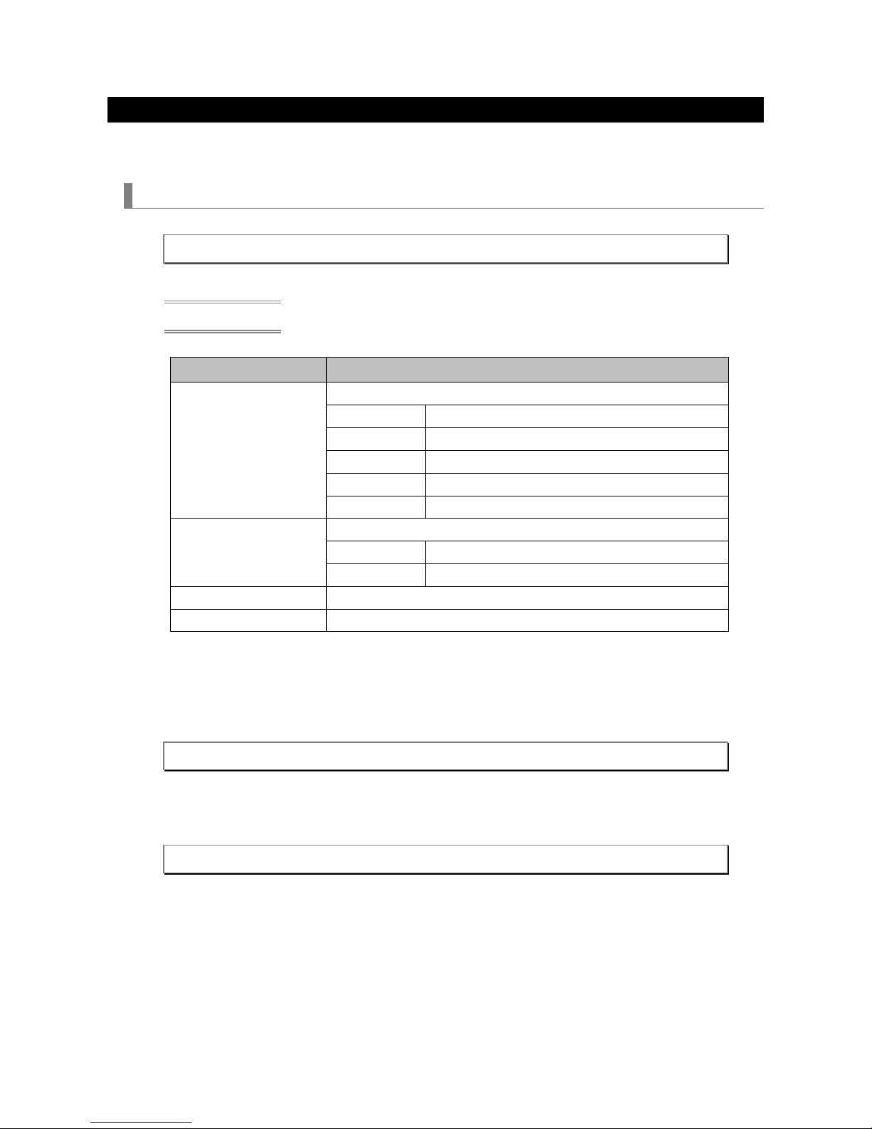
1.2 Communication conditions
For information about the connection methods available for the model in use, see the Appendix "Connecting an
External Device".
Serial connection
The RS-232C-compliant communication method is supported. Specify the communication settings of the software
used to send and receive commands, as shown below.
Item Detail
Baud rate 115200/38400/19200/9600/4800 bps
Data length 8 bits
Parity bit None
Stop bit 1 bit
Communication mode Full duplex
LAN connection
4 Wired LAN
Item Detail
Data rate Auto switchable (10/100 Mbps)
Supported standard IEEE802.3 (10BASE-T)
IEEE802.3u (100BASE-TX, Auto-Negotiation)
4 Wireless LAN
See the operation manual of the wireless LAN unit to be used.
4 Port number
Use TCP port number "7142" for sending and receiving commands.

8
2. Command List
Command Description Page to
see
009. ERROR STATUS REQUEST Gets information about errors occurring in the projector. 13
015. POWER ON Turns on the power of the projector. 15
016. POW ER OFF Turns off the power of the projector. 16
018. INPUT SW CHANGE Switches the input terminal or entry list. 17
020. PICTURE MUTE ON Turns the picture mut e on. 19
021. PICTURE MUTE OFF Turns the picture mut e off. 20
022. SOUND MUTE ON Turns the sound mute on. 21
023. SOUND MUTE OFF Turns the sound mute off. 22
024. ONSCREEN MUTE ON Turns the onscreen mute on. 23
025. ONSCREEN MUTE OFF Turns the onscreen mute off. 24
030-1. PICT URE ADJUST Adjusts the picture. 25
030-2. VOLUME ADJUST Adjusts the s ound volume. 27
030-12. ASPECT ADJUST Adjusts the aspect. 29
030-15. OTHER ADJUST Adjusts the various gains. 30
037. INFOR MATION REQUEST Gets the information of the projector. 32
037-3. FILTER USAGE INFORMATION REQUEST Gets filter us age information such as usage ti me. 33
037-4. LAMP INFORMATION REQUEST 3 Gets lamp inf ormation such as us age time and remaining lif e.
34
037-6. CARBON SAVINGS INFORMATION REQUEST Gets the Carbon Saving values on t he projector. 36
050. REMOTE KEY CODE Sends the key code for remote control. 38
053. LENS CONTROL Adjusts the lens position. 40
053-1. LENS CONTROL REQUEST Gets adjust ed values of the lens position. 42
053-2. LENS CONTROL 2 Adjusts the lens position. 44
053-3. LENS MEMORY CONTROL Controls the lens memory. 46
053-4. REF ERENCE LENS MEMORY CONTROL Controls the reference lens memory. 48
053-5. LENS ME MORY OPTION REQUEST Gets the value set for the lens memory. 50
053-6. LENS MEMORY OPTION SET Sets the lens memory. 51
053-7. LENS INFORMATION REQUEST Gets information about the lens of the projector. 53
053-10. LENS PROFILE SET Selects the profile number of the reference lens memory. 54
053-11. LENS PRO FILE REQU EST Gets the selected profile number of the reference lens
memory.
55
060-1. GAIN PARAMETER REQUEST 3 Gets adjust ed values of the picture, volume, and backlight. 56

9
Command Description Page to
see
078-1. SETTING REQUEST Gets information of the projector. 58
078-2. RUNNING STATUS REQUEST Gets the information about the operation status of the
projector.
59
078-3. INPUT STATUS REQUEST Gets the information about the input signal status of the
projector.
60
078-4. MUTE STATUS REQUEST Gets the mute status of the projector. 62
078-5. MODEL NAME REQUEST Gets the model name of the projector. 64
078-6. COVER STATUS REQUEST Gets the status of the mirror cover or lens cover. 65
079. FREEZE CONTROL Controls whether to turn the freeze functi on on or off. 66
084. INFOR MATION STRING REQUEST Gets information strings (Englis h) displayed on the projector. 67
097-8. ECO MODE REQUEST Gets the value set for the eco mode. 68
097-45. LAN PROJECTOR NAME REQU EST Gets the projector name. 69
097-155. LAN MAC ADDRESS STATUS REQUEST2 Gets the MAC address of the projector. 70
097-198. PIP/PICTURE BY PICTURE REQUEST Gets the value set for the picture in picture and picture by
picture.
71
097-243-1. EDGE BLEND ING MODE REQUEST Gets the value set for the edge blending. 73
098-8. ECO MODE SET Sets the eco mode. 74
098-45. LAN PROJECTOR NAME SET Sets the projector name. 75
098-198. PIP/PICTURE BY PICTURE SET Sets the picture in picture or picture by picture. 76
098-243-1. EDGE BLENDING MODE SET Sets the edge blending. 78
305-1. BASE MODEL TYPE REQUEST Gets the base model type of the projector. 79
305-2. SERIAL NUMBER REQUEST Gets the serial number of the projector. 80
305-3. BASIC INFORMATION REQUEST Gets the operation status of the projector. 81
319-10. AUDIO SELECT SET Sets the audio select. 83

10
2.1 Understanding command details
In this manual, commands and responses are expressed as follows.
20h 88h <ID1> <ID2> 0Ch <DATA01> - <DATA12> <CKS>
Command/response A s eries of strings enclosed in a fr ame represents a command or response (in
hexadecimal notation).
Parameter A character string in italic enclosed in brackets represents a parameter.
For information about the parameters that ar e common to the contr ol commands
(ID1, ID2, CKS, LEN, ERR1, and ERR2), see "2.2 Paramet ers" (page 10). For
information about those parameters whose c ontent varies from command to
command (DATA), see the description of the relevant c ommand.
2.2 Parameters
The parameters that are used in the control commands are listed below.
Parameter name Description
ID1 Control ID The value of the "control ID" s et for the projector is used.
ID2 Model code This varies depending on the model in us e.
CKS Checksum The checksum is c alculated as f ollows.
① Add all preceding bytes of data.
② Use the value of the low-order one byte (eight bits) of the addition
result obtained in ① as the checksum.
LEN Data length This indicates the data length of the data part (DATA??) following LEN (in
bytes).
DATA?? Variable length data This varies depending on the character string stored.
ERR1
ERR2
Response err or The c ause of an error is r epres ented b y a combination of error codes.
For information about error codes, s ee "2.4 Error code list" (page 12).
Example of checksum calculation
20h 81h 01h 60h 01h 00h <CKS>
① Add all the data preceding the checksum.
"20h + 81h + 01h + 60h + 01h + 00h = 103h"
② Use the low-order one byte "03h" of the addition result obtained in ① as the checksum.

11
2.3 Responses
After a command is sent to the projector, its result is returned as a response. How a response is returned differs
depending on the execution result of the command.
When the execution of a command succeeds
When the command does not request data, a response is returned with no data part.
When the command requests data, a response is returned with data added to data parts.
When the execution of a command fails
A response is returned with the cause of the failed command execution indicated in <ERR1> and <ERR2>.
(Example) POWER ON
4 Command
02h 00h 00h 00h 00h 02h
4 Response
A2h 00h <ID1> <ID2> 02h <ERR1> <ERR2> <CKS>

12
2.4 Error code list
The following table lists the combinations of error codes (ERR1 and ERR2) and describes the error indicated by each
combination.
ERR1 ERR2 Error description
00h 00h The command cannot be recognized.
00h 01h The command is not supported by the model in use.
01h 00h The specified value is invalid.
01h 01h The specified input terminal is invalid.
01h 02h The specified language is invalid.
02h 00h Memory allocation error
02h 02h Memory in use
02h 03h The specified value cannot be set.
02h 04h Forced onscreen mute on
02h 06h Viewer error
02h 07h No signal
02h 08h A test pattern or filer is displayed.
02h 09h No PC card is inserted.
02h 0Ah Memory operation error
02h 0Ch An entry list is displayed.
02h 0Dh The command cannot be accepted becaus e the power is off.
02h 0Eh The c ommand execution failed.
02h 0Fh Ther e is no authority necessary f or the operation.
03h 00h The specified gain number is incorrect.
03h 01h The specified gain is invalid.
03h 02h Adjustment failed.

13
3. Command details
3.1 [ 009. ERROR STATUS REQUEST ]
Gets information about errors occurring in the projector.
Command
00h 88h 00h 00h 00h 88h
Response
4 When the command succeeds
20h 88h <ID1> <ID2> 0Ch <DATA01> - <DATA12> <CKS>
4 When the command fails
A0h 88h <ID1> <ID2> 02h <ERR1> <ERR2> <CKS>
Data part
¡ DATA1 - DATA12 ............. Error information is provided. A bit set to "0" indicates that the data is normal, and a bit
set to "1" indicates an error. For an error information list, see the next page.

14
<Error information list>
Item
Description
DATA01 Error status (1)
Bit0 Cover error Bit4 Fan error
Bit1 Temperature error (bi-metallic
strip)
Bit5 Power error
Bit2 None (fixed to 0) Bit6 Lamp (or lamp 1) off
or backlight off
Bit3 Fan error Bit7 Lamp (or lamp 1) in a replacement
moratorium
DATA02 Error status (2)
Bit0 Lamp (or lamp 1) usage time
exceeded the limit
Bit4 None (fixed to 0)
Bit1 Formatter error Bit5 None (fixed to 0)
Bit2 Lamp 2 off Bit6 None (fixed to 0)
Bit3 None (fixed to 0) Bit7 Refer to th e extend status.
DATA03 Error status (3)
Bit0 None (fixed to 0) Bit4 Lamp (or lamp 1) data err or
Bit1 FPGA error Bit5 Mirror cover error
Bit2 Temperature error (temperature
sensor)
Bit6 Lamp 2 in a replacement
moratorium
Bit3 Lamp (or lamp 1) not present Bit7 Lamp 2 usage time exceeded the
limit
DATA04 Error status (4)
Bit0 Lamp 2 not present Bit4 None (fixed to 0)
Bit1 Lamp 2 data error Bit5 Ballast communication error
Bit2 Temperature error due to dust Bit6 Iris calibration error
Bit3 Foreign matter sensor error Bit7 The lens is not installed properly.
DATA05 - 08 Reserved for the system
DATA09 Extended status
Bit0 The portrait cover side is up Bit4 None (fixed to 0)
Bit1 The interlock switc h is open. Bit5 None (fixed to 0)
Bit2 System error has occurred.
(Slave CPU)
Bit6 None (fixed to 0)
Bit3 System error has occurred
(Formatter)
Bit7 None (fixed to 0)
DATA10 - 12 Reserved f or the system

15
3.2 [ 015. POWER ON ]
Turns on the power of the projector.
Information
While this command is turning on the power, no other command can be accepted.
Command
02h 00h 00h 00h 00h 02h
Response
4 When the command succeeds
22h 00h <ID1> <ID2> 00h <CKS>
4 When the command fails
A2h 00h <ID1> <ID2> 02h <ERR1> <ERR2> <CKS>

16
3.3 [ 016. POWER OFF ]
Turns off the power of the projector.
Information
While this command is turning off the power (including the cooling time), no other command can be accepted.
Command
02h 01h 00h 00h 00h 03h
Response
4 When the command succeeds
22h 01h <ID1> <ID2> 00h <CKS>
4 When the command fails
A2h 01h <ID1> <ID2> 02h <ERR1> <ERR2> <CKS>

17
3.4 [ 018. INPUT SW CHANGE ]
Switches the input terminal or entry list.
Command
02h 03h 00h 00h 02h 01h <DATA01> <CKS>
Data part
Item Description
DATA01 Input terminal
Information
For the values of input terminal, see the Appendix "Supplementary Information by Command".
4 Command example
The following command switches the input terminal to a video port (DATA01: 06h).
02h 03h 00h 00h 02h 01h 06h 0Eh

18
Response
4 When the command succeeds
22h 03h <ID1> <ID2> 01h <DATA01> <CKS>
Data part
Item Description
DATA01 Execution result
00h Ended successfully.
FFh Ended with an error (no signal switch is made).
4 When the command fails
A2h 03h <ID1> <ID2> 02h <ERR1> <ERR2> <CKS>

19
3.5 [ 020. PICTURE MUTE ON ]
Turns the picture mute on.
Information
If any of the following operations is done, the picture mute is turned off.
・ Input terminal switch
・ Video signal switch
Command
02h 10h 00h 00h 00h 12h
Response
4 When the command succeeds
22h 10h <ID1> <ID2> 00h <CKS>
4 When the command fails
A2h 10h <ID1> <ID2> 02h <ERR1> <ERR2> <CKS>

20
3.6 [ 021. PICTURE MUTE OFF ]
Turns the picture mute off.
Command
02h 11h 00h 00h 00h 13h
Response
4 When the command succeeds
22h 11h <ID1> <ID2> 00h <CKS>
4 When the command fails
A2h 11h <ID1> <ID2> 02h <ERR1> <ERR2> <CKS>

21
3.7 [ 022. SOUND MUTE ON ]
Turns the sound mute on.
Information
If any of the following operations is done, the sound mute is turned off.
・ Input terminal switch
・ Video signal switch
・ Sound volume adjustment
Command
02h 12h 00h 00h 00h 14h
Response
4 When the command succeeds
22h 12h <ID1> <ID2> 00h <CKS>
4 When the command fails
A2h 12h <ID1> <ID2> 02h <ERR1> <ERR2> <CKS>

22
3.8 [ 023. SOUND MUTE OFF ]
Turns the sound mute off.
Command
02h 13h 00h 00h 00h 15h
Response
4 When the command succeeds
22h 13h <ID1> <ID2> 00h <CKS>
4 When the command fails
A2h 13h <ID1> <ID2> 02h <ERR1> <ERR2> <CKS>

23
3.9 [ 024. ONSCREEN MUTE ON ]
Turns the onscreen mute on.
Information
If any of the following operations is done, the onscreen mute is turned off.
・ Input terminal switch
・ Video signal switch
Command
02h 14h 00h 00h 00h 16h
Response
4 When the command succeeds
22h 14h <ID1> <ID2> 00h <CKS>
4 When the command fails
A2h 14h <ID1> <ID2> 02h <ERR1> <ERR2> <CKS>

24
3.10 [ 025. ONSCREEN MUTE OFF ]
Turns the onscreen mute off.
Command
02h 15h 00h 00h 00h 17h
Response
4 When the command succeeds
22h 15h <ID1> <ID2> 00h <CKS>
4 When the command fails
A2h 15h <ID1> <ID2> 02h <ERR1> <ERR2> <CKS>
25
3.11 [ 030-1. PICTURE ADJUST ]
Adjusts the picture.
Command
03h 10h 00h 00h 05h <DATA01> FFh <DATA02> - <DATA04> <CKS>
Data part
Item Description
DATA01 Adjustment target
00h Brightness
01h C ontrast
02h C olor
03h Hue
04h Sharpness
DATA02 Adjustment mode
00h Specify an absolute value
01h Specify a relative value
DATA03 Adjustment value (low-order 8 bits)
DATA04 Adjustment value ( high-order 8 bits)
4 Command example
① The following command sets brightness to "10".
03h 10h 00h 00h 05h 00h FFh 00h 0Ah 00h 21h
② The following command sets brightness to "-10".
03h 10h 00h 00h 05h 00h FFh 00h F6h FFh 0Ch

26
Response
4 When the command succeeds
23h 10h <ID1> <ID2> 02h <DATA01> <DATA02> <CKS>
Data part
Item Description
DATA01
DATA02
Execution result
0000h Ended successfully.
Other than 0000h Ended with an error.
4 When the command fails
A3h 10h <ID1> <ID2> 02h <ERR1> <ERR2> <CKS>

27
3.12 [ 030-2. VOLUME ADJUST ]
Adjusts the sound volume.
Command
03h 10h 00h 00h 05h 05h 00h <DATA01> - <DATA03> <CKS>
Data part
Item Description
DATA01 Adjustment mode
00h Specify an absolute value
01h Specify a relative value
DATA02 Adjustment value (low-order 8 bits)
DATA03 Adjustment value ( high-order 8 bits)
4 Command example
The following command set the sound volume to "10".
03h 10h 00h 00h 05h 05h 00h 00h 0Ah 00h 27h

28
Response
4 When the command succeeds
23h 10h <ID1> <ID2> 02h <DATA01> <DATA02> <CKS>
Data part
Item Description
DATA01
DATA02
Execution result
0000h Ended successfully.
Other than 0000h Ended with an error.
4 When the command fails
A3h 10h <ID1> <ID2> 02h <ERR1> <ERR2> <CKS>

29
3.13 [ 030-12. ASPECT ADJUST ]
Adjusts the aspect.
Command
03h 10h 00h 00h 05h 18h 00h 00h <DATA01> 00h <CKS>
Data part
Item Description
DATA01 Value set for the aspect
Information
For information about the values set for the aspect, see the Appendix "Supplementary Information by
Command".
Response
4 When the command succeeds
23h 10h <ID1> <ID2> 02h <DATA01> <DATA02> <CKS>
Data part
Item Description
DATA01
DATA02
Execution result
0000h Ended successfully.
Other than 0000h Ended with an error.
4 When the command fails
A3h 10h <ID1> <ID2> 02h <ERR1> <ERR2> <CKS>
 Loading...