

Page 1
Quick Install Guide – SL2100 Terminals Type B rev 1.0 1
The SL2100
Quick Install Guide:
Terminals
Type B (2w)
www.nec-enterprise.com
Page 2

Quick Install Guide – SL2100 Terminals Type B rev 1.0 2
This guide explains the installation, configuration and operation of the SL2100 Type B Terminals (2 wire)
including the audio and relay connections of the interface card.
Further information is available on BusinessNet.
Please keep all information supplied for future reference.
Regulatory Notice.
Refer to the Declaration of Conformity, Regulatory and Safety Considerations shown in the SL2100 Hardware
Manual.
Warning: This is a class A product. In a domestic environment this product may cause radio interference in
which case the user may be required to take adequate measures.
Page 3

Quick Install Guide – SL2100 Terminals Type B rev 1.0 3
Contents
Digital Type B Terminals ........................................................................................................................................ 4
Parts available for the SL2100 ........................................................................................................................... 5
IP7WW-082U-B1 Interface Card ............................................................................................................................. 6
1- Unpack the IP7WW-082U-B1 Card .................................................................................................................... 7
2- Install the IP7WW-082U-B1 Card ....................................................................................................................... 8
3- Connect the Telephones .................................................................................................................................... 9
Connecting to the RJ45 sockets of the IP7WW-082U-B1 card .......................................................................... 9
Terminating extensions at RJ11 or RJ45 face plates at the user’s desk. ........................................................12
4- Connect DSS Consoles .................................................................................................................................... 13
5- Connect Doorphones ....................................................................................................................................... 13
6- Connect External Sensors ............................................................................................................................... 14
7- Connect the Power & System Start Up .......................................................................................................... 15
8- Configure the SL2100 ....................................................................................................................................... 16
Connecting PCPro to the SL2100 ....................................................................................................................16
SL2100 PCPro..................................................................................................................................................17
Port Assignment of the IP7WW-082U-B1 card ................................................................................................18
DSS Console and Operator ..............................................................................................................................19
Operator Extension ..........................................................................................................................................20
Analogue Extensions ........................................................................................................................................21
Timed Break Recall (TBR) / Hook Flash ..........................................................................................................24
Doorphones and Door Lock Relay Contacts ....................................................................................................25
What to do if you make errors within the SL2100 Configuration ......................................................................26
Page 4
SL2100 Digital Terminals – Type B (2w)
Quick Install Guide – SL2100 Terminals Type B rev 1.0 4
Digital Type B Terminals
The SL2100 system consists of a chassis unit that supports the installation of
either Type A or Type B digital terminals, as only one terminal type can be
installed there are separate Quick Install Guides for each.
This guide details the installation of Type B terminals.
Refer to the following Quick Install Guide for other terminals:
Quick Install Guide – Digital Terminals Type A
Quick Install Guide – IP Terminal 8IPLD
Quick Install Guide – IP Terminals DT820
Digital
Terminal
Connect to interface card
Terminal wiring
Type A
IP7WW-308U-A1 or IP7WW-008U-C1
4 wire connection
Type B
IP7WW-082U-B1
2 wire connection
This guide also includes details of installing the external Music on Hold, Background Music, Paging and Relay
connections as these are provided by the interface card.
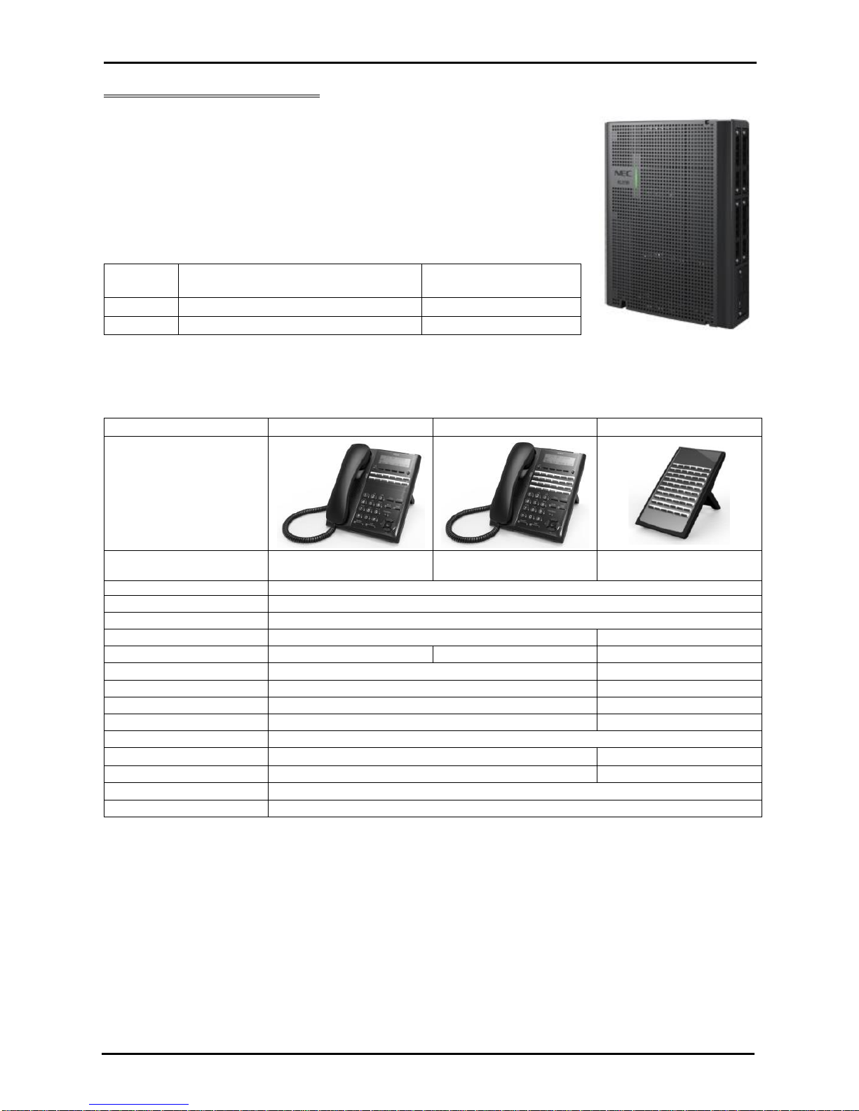
SL2100 Type B Digital Terminals
12 Button
24 Button
60 Button DSS
Part code & description
BE116515
IP7WW-12TXH-B1 TEL
BE116516
IP7WW-24TXH-B1 TEL
BE116519
IP7WW-60D-B1 CONSOLE
Connected to
Digital Extension Port
Power feeding
From digital extension port
Colour
Black
Display
24 digits x 3 lines with backlight
None
Programmable keys
12 (red/green)
24 (red/green)
60 (red/green)
Soft keys 4 None
Menu curser keys
Yes
No
Incoming call lamp
Yes (red/green)
No
Handsfree
Yes (full duplex)
No
Backlit dial pad
No
Headset Port
Yes (RJ11 connector)
No
EHS support
Yes (using WHA BE113158)
No
Angle Adjustment
Yes (2 steps)
Wall Mounting
Yes (built in)
Page 5

SL2100 Digital Terminals – Type B (2w)
Quick Install Guide – SL2100 Terminals Type B rev 1.0 5
Parts available for the SL2100
Not all parts are included within this guide, please refer to the other SL2100 Quick Install Guides or the SL2100
Hardware Manual for a full description and installation instructions of all parts available.
IP7WW-4KSU-C1
SL1100 Chassis unit
IP7EU-CPU-C1
SL2100 CPU card
IP7EU-CPU-C1-A
SL2100 CPU card with preinstalled IP licenses and 2hour
InMail
IP7WW-082U-B1
8 Digital Extension (2wire) and 2
SLT extension card
8 digital and 2 SLT extension interfaces, max
3 per unit
IP7WW-008U-C1
8 Hybrid Extensions card for
digital (4wire) extensions or SLT
extension
8 SLT extension interfaces, max 4 per unit
IP7WW-12TXH-B1 TEL
(BK)
12 Keys, Digital (2W) Multiline
Terminal (Black)
IP7WW-24TXH-B1 TEL
(BK)
24 Keys, Digital (2W) Multiline
Terminal (Black)
IP7WW-60D DSS-B1
CONSOLE (BK)
60 Keys, Digital (2W) DSS
Console (Black)
DX7NA-WHA-A1
Cordless Headset Adapter
DX4NA Doorphone
Doorphone
Refer to Prophix for all parts and licenses available in your region.
Page 6
SL2100 Interface Card
Quick Install Guide – SL2100 Terminals Type B rev 1.0 6
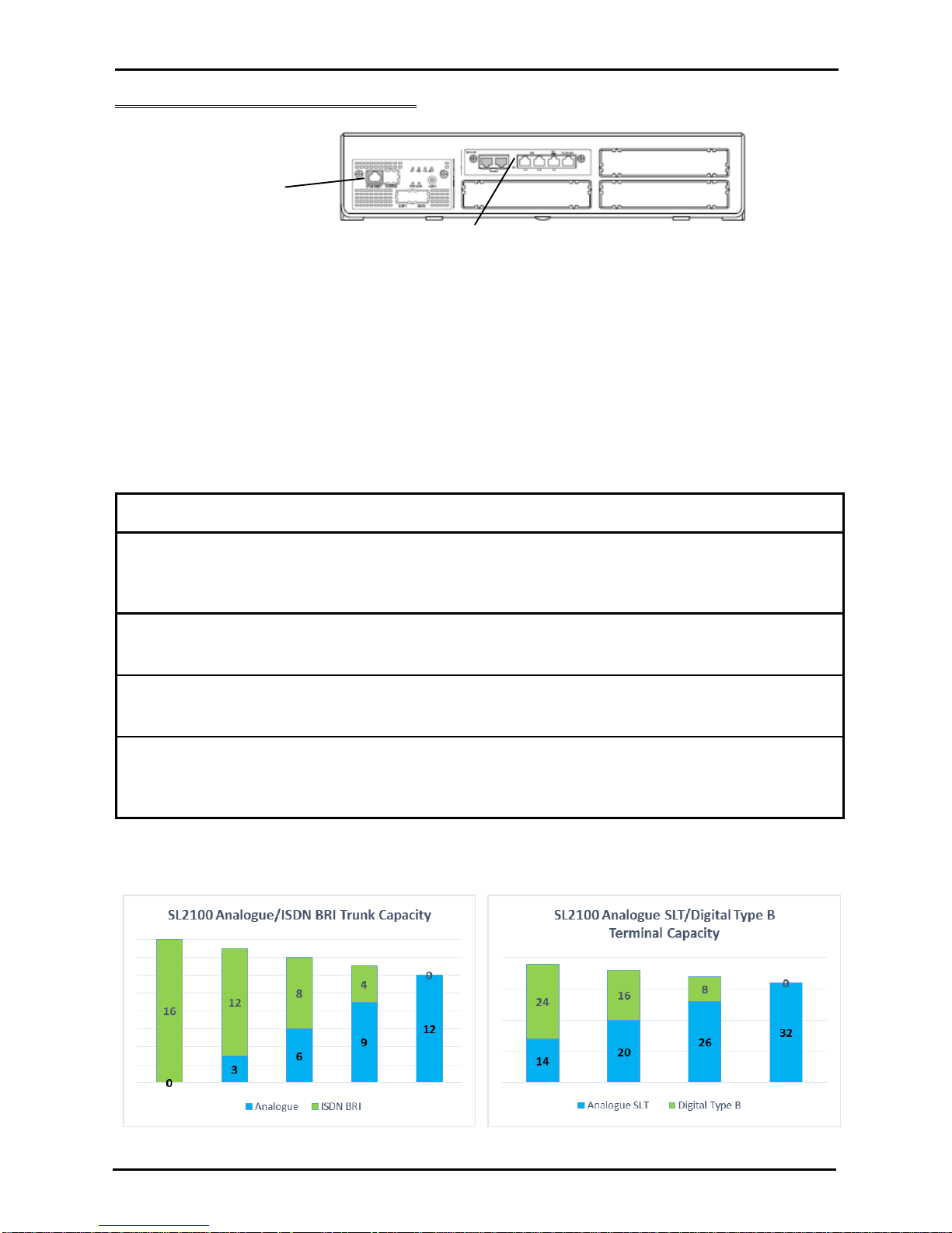
IP7WW-082U-B1 Interface Card
SL2100 chassis showing the CPU card with an extension interface card installed.
The card provides:
8 x Digital extension ports
2 x Analogue SLT extensions ports
1 x Connector for mounting a trunk daughter card
1 x External Music on Hold/Background Music audio input
1 x External Paging audio output
2 x Relay contacts (for external device or door lock control)
The card can be installed into any of the universal slots S1~S3.
Note – Slot S4 does not support digital extensions, an IP7WW-082U-B1 card can be installed but will only
support the two analogue extensions and any trunk daughter card.
SL2100 Capacity
Item
Maximum capacity
in a single chassis
TDM Trunks
42
There is a trade-off between each trunk type, see below
Analogue
12
ISDN BRI
16
ISDN PRI
30
TDM Extensions
32
There is a trade-off between each extension type, see
below
Analogue SLT
32
Digital
24
Maximum IP
176
IP capacity is independent of the TDM capacity
IP Trunks
64
IP Extensions
112
External Music on Hold
1
External Background Music
1
External Paging
3
Relays
6
Trade-off between TDM interfaces (for simplicity does not include PRI trunks, Refer to the Quick Install Guide for
PRI trunk capacity).
SL2100 Trunk capacity for a single chassis
SL2100 Terminal capacity for a single chassis
Extension
Interface card
SL2100 CPU card
Page 7

Unpack the IP7WW-082U-B1 Card
Quick Install Guide – SL2100 Terminals Type B rev 1.0 7
1- Unpack the IP7WW-082U-B1 Card
SL2100 Extension Interface card
1 x Interface card
Additional Items Required:
Cross head screwdriver.
Utility knife or small cutters to remove the plastic knockouts
Solid wire for extending telephone cabling:
Recommended cable type: Twisted pair (CW1308 or similar specification)
Conductor diameter: 0.4 to 0.6 mm
Maximum cable length: (with 0.5 mm diameter cable)
SL2100 system telephone – 300 metres
Normal telephone (SLT) – 1125 metres
Page 8
Install the IP7WW-082U-B1 Card
Quick Install Guide – SL2100 Terminals Type B rev 1.0 8
2- Install the IP7WW-082U-B1 Card
The SL2100 chassis does not have any cards pre-installed, you install the extension interface card of your
choice.
! Ensure the SL2100 is powered off before removing/installing any card.
You may also have a trunk daughter card to mount onto the IP7WW-082U-B1 card, refer to the Quick Install
Guide for the trunk card type for installation details.
The following trunk daughter cards may be mounted
IP7WW-3COIDB-C1
3 Analogue trunks
IP7WW-2BRIDB-C1
2 ISDN BRI circuits (4 trunk channels)
IP7WW-1PRIDB-C1
1 ISDN PRI circuit (30 trunk channels)
Each IP7WW-082U-B1 card can have one daughter card mounted.
If you are connecting a doorphone unit then you must set the hardware links before mounting a trunk daughter
card and installing the card into the chassis, refer to the Doorphone section later in this guide.
Note – Slot 4 does not support digital extensions, an IP7WW-082U-B1 card can be installed but will only support
analogue extensions, any trunk daughter card is supported in slot 4.
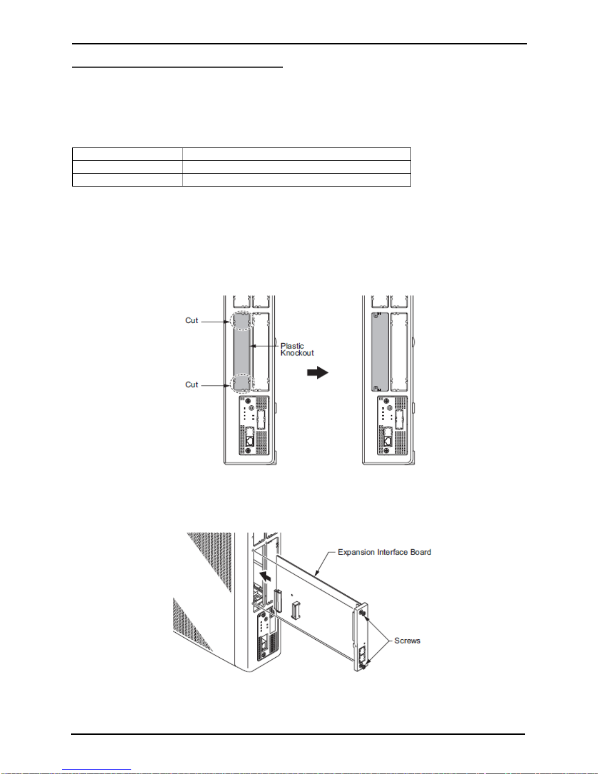
Remove the plastic knockout from the slot on the front of the SL2100 chassis.
Note – the knockout can not be replaced once removed; there are no blanking covers available, be sure to
remove the correct knockout.
Insert the interface card into the SL2100 universal slot, ensure the card slides into the guide rails and tighten the
two screws to secure the card.
Page 9

Connect the Telephones
Quick Install Guide – SL2100 Terminals Type B rev 1.0 9
3- Connect the Telephones
The connectors of the IP7WW-082U-B1 card have multiple extension ports per RJ45 connector using the RJ61
pin-out format.
Connecting to the RJ45 sockets of the IP7WW-082U-B1 card
The are several methods available to connect these interfaces into the customer’s building infrastructure.
1. Use the cable assembly, adapter or panel available from NEC
Cable LPNEC4 – 2m length, converts a four port RJ45 socket to four RJ45 plugs, one port per plug.
Can be used to connect into an RJ45 through coupler panel or directly into the customer’s
panels.
Can also be used to plug into RJ45 face plates if IDC termination is required.
Cable colour: black
One cable is required for each ESI socket of the IP7WW-082U-B1 card.
Ports 1~4
RJ45 plug
Pin
1 - 2 - 3
-
4 R 5 T 6
-
7
-
8
-
Page 10

Connect the Telephones
Quick Install Guide – SL2100 Terminals Type B rev 1.0 10
Cable LPNEC2 – 2m length, converts a two port RJ45 socket to two RJ45 plugs, one port per plug.
Can be used to connect into an RJ45 through coupler panel or directly into the customer’s
panels.
Can also be used to plug into RJ45 face plates if IDC termination is required.
Cable colour: black
One cable is required for the SLI socket of the IP7WW-082U-B1 card.
Adapter ADNEC14 – Converts a four port RJ45 socket to four RJ45 sockets, one port per socket.
Requires five patch cables of the desired length and colour.
Can be used to connect into an RJ45 through coupler panel or directly into the customer’s panels.
Can also be used to plug into RJ45 face plates if IDC termination is required.
Colour: black
Supplied with an adhesive pad.
One adapter is required for each ESI and SLI socket of the IP7WW-082U-B1 card.
Ports 1~2
RJ45 plug
Pin 1 - 2 - 3
-
4 R 5 T 6
-
7 - 8
-
Ports 1~4
RJ45 sockets
Pin
1 - 2 - 3 - 4 R 5
T
6
-
7
-
8
-
Page 11

Connect the Telephones
Quick Install Guide – SL2100 Terminals Type B rev 1.0 11
16/24/40 Port Panels FFV16NECBK/FFV24NECBK/FFNEC50
Converts 4/6/12 RJ45 sockets to 16/24/40 RJ45 sockets, one port per socket.
Requires 4/6/12 patch cables of the desired length and colour to connect to the SL2100 plus 16/24/40 patch
cables to connect into the customer’s panels.
Colour: black
Can be used for the ESI, SLI and Audio sockets of the IP7WW-082U-B1 card.
Note – when used for the two port SLI socket only ports 1~2 will be used.
Ports
1~16/24/40
RJ45 sockets
Pin 1 - 2 - 3 - 4 R 5 T 6
-
7 - 8
-
Page 12

Connect the Telephones
Quick Install Guide – SL2100 Terminals Type B rev 1.0 12
2. Terminate cables on site with RJ45 plugs and connect directly to the RJ45 sockets of the IP7WW-082U-B1
card.
Use the following pin-out to terminate each RJ45 plug.
ESI 1-4
ESI 5-8
Pin
No.
Port
SLI 1-2
Pin
No.
Port
1
4
1
2
3
2
3
2
3
2
4
1
4 1
5
1
5 1
6
2
6
2
7
3
7
8
4
8
3. Use pre-terminated RJ45 patch cables and connect directly to the RJ45 sockets of the IP7WW-082U-B1
card.
Use the following cable colours when using a straight through RJ45 patch cable directly into the RJ45 sockets of
the IP7WW-082U-B1 card.
Using an RJ45 patch
cable into the RJ45
connectors
SLI 1-2
ESI 1-4
ESI 5-8
Pin
No.
Port
RJ45 Colour code
Port
1
4
White/Orange
2
3
Orange/White
3
2
White/Green
2
4
1 Blue/White
1
5
1 White/Blue
1
6
2
Green/White
2
7
3 White/Brown
8
4 Brown/White
Terminating extensions at RJ11 or RJ45 face plates at the user’s desk.
Each port connects to
RJ11 = Connections 3 & 4
RJ45 = Blue/White connections
Each port connects to
RJ11 = Connections 3/4
RJ11 Face plate
Pin
Connection
1 - 2
-
3 R 4 T 5
-
6
-
RJ45 = Blue/White connections
RJ45 Face plate
Pin
Connection
1
-
2 - 3 - 4
R
5 T 6 - 7 - 8
-
87654321
87654321
87654321
Page 13

Connect the DSS Console and Doorphone
Quick Install Guide – SL2100 Terminals Type B rev 1.0 13
4- Connect DSS Consoles
Up to eight DSS consoles can be connected to the eight digital extension ports of the IP7WW-082U-B1 card.
The maximum system capacity is 12 consoles.
Each DSS console is assigned to a digital extension with PCPro, up to 4 consoles can be assigned to the same
extension.
5- Connect Doorphones
Up to two doorphones (BE109741 – DX7NA) can be connected to the analogue extension ports of the IP7WW082U-B1 card.
The maximum system capacity is 6 doorphones.
Each analogue port of the IP7WW-082U-B1 card
has hardware links to select SLT/doorphone
operation.
The factory setting is SLT operation.
Ensure you set the hardware links as shown.
The hardware links set the mode, there is no
additional system configuration required to select
SLT/doorphone operation
You will need to remove any trunk daughter card to
access the hardware links.
Terminating at the doorphone
Each port connects to: & at the doorphone.
The connections to the doorphone are none polarity.
Pin
SLI 1-2
RJ45 socket
1 - 2
-
3
Door 2 T
4
Door 1 R
5
Door 1 T
6
Door 2 R
7
-
8
-
Rear of
doorphone
Page 14

Connect the External Sensors
Quick Install Guide – SL2100 Terminals Type B rev 1.0 14
6- Connect External Sensors
The SL2100 can be used to detect the operation of external sensors by connecting to the analogue extension
port that is set to doorphone mode.
The external sensor can be any normally open contact (Form A) for example, push button/panic switch or PIR
detector with a suitable specification.
When the external sensor is closed/activated the SL2100
system will ring a group of extensions in the same way as
the doorphone would.
Description
Specification
External
sensor
Voltage during sensor off (contact open): 25V
Loop current during sensor on/activated (contact closed) : 40mA
Pin
SLI 1-2
RJ45 socket
1
-
2
-
3
Door / sensor 2 T
4
Door / sensor 1 R
5
Door / sensor 1 T
6
Door / sensor 2 R
7
-
8
-
Page 15

Connect the Power & System Start Up
Quick Install Guide – SL2100 Terminals Type B rev 1.0 15
7- Connect the Power & System Start Up
The power cable is plugged into the left side (wall mounted) or rear (when rack mounted) of the unit via an IECC13 connector.
Before connecting the power:
Ensure the power switch is OFF
Ensure the power is switched off at the source
All cards are installed and secured correctly
System Start Up – First Time
! The first time you start up the SL2100 it is important to clear the system memory. This will ensure that the
system is set to the default/factory configuration.
1. Push and hold the LOAD Button located on the front of the CPU card.
2. Turn the power switch on
3. Continue holding the LOAD Button for approximately 10 seconds or until the ALM lamp on the CPU card
lights.
4. Release the LOAD Button
5. When the system has completed reloading the system software (about one minute) the RUN LED is
flashing green on the CPU card and the system phones will display the Time and Date.
Switching the SL2100 OFF
! Be sure that no calls are in progress otherwise they will be cut off.
Turn the power switch OFF at the SL2100 chassis.
System Start Up – Retain Customer Configuration
This is the normal operation for powering the SL2100 on.
Turn the power switch ON at the SL2100 chassis.
Any new installed cards will be automatically detected.
Also referred to as ‘COLD Start’
can also be used at any time to
delete the customer’s
configuration.
Warning – COLD Start should
only be used when you want to
delete the customer’s
configuration from the SL2100
CPU card.
AC Power
cable
Power
switch
Page 16

Configure the SL2100
Quick Install Guide – SL2100 Terminals Type B rev 1.0 16
8- Configure the SL2100
This Quick Install guide will cover the most frequently used configuration options. For advanced configuration
please refer to the SL2100 Features and Specifications manual.
You must have SL2100 PCPro installed to your laptop/PC, this can be downloaded from BusinessNet, refer to
the Quick Install Guide – SL2100 PCpro.
The SL2100 can also be configured via an SL2100 System phone or via a WebPro interface, these are not
included within this guide.
Before you configure your system it is important that you:
Have a diagram of your exchange lines and telephones.
Plan your requirements before you start.
While you configure your system it is advised that you:
Make a record of your configuration as you make each change.
Make small changes, upload to the SL2100 and test the changes. Avoid making all your changes at
once as this can make testing more difficult.
With the default/factory settings:
Each telephone will function and is assigned an extension number (200~211).
Calls received on the exchange lines will ring at telephone number 200.
Each telephone can make exchange line calls by dialing 0.
Each exchange line is presented at a Function Key with busy lamp indication.
Connecting PCPro to the SL2100
CPU Default IP Address:
192.168.0.10 / 255.255.255.0
You can check the IP address at any SL2100 system phone:
Press the centre Navigation Key and dial 841
Direct to Ethernet connector on the SL2100 CPU card.
Via the customer’s LAN.
Page 17

Configure the SL2100
Quick Install Guide – SL2100 Terminals Type B rev 1.0 17
SL2100 PCPro
Installer level access:
User Name: tech
Password: 12345678
On first install you may need to setup the default sliding panes if you wish to use these.
Select View tab and click Default
Page 18

Configure the SL2100
Quick Install Guide – SL2100 Terminals Type B rev 1.0 18
Port Assignment of the IP7WW-082U-B1 card
Go to the Chassis View to confirm the ports assigned to the cards installed within the SL2100 system.
IP7WW-308U-A1 card
Clicking on any of the interfaces will show the appropriate Properties Pane where you can configure the selected
port.
Audio and Paging
Digital extensions
Doorphone
Analogue
extension
Port designation
Edit each item
within the
Properties pane
Click the Extension button to open
the Easy Edit screen to edit all
extension names and numbers
Page 19

Configure the SL2100
Quick Install Guide – SL2100 Terminals Type B rev 1.0 19
DSS Console and Operator
One DSS consoles can be connected to any digital extension port of the IP7WW-082U-B1 card.
The SL2100 will automatically detect the DSS console when it’s connected.
1. Go to the Chassis View and click the DSS console.
2. Assign the console to the extension that it will be used with
3. Setup the keys of the DSS console
Click the DSS
console
Enter the extension that
the console will be used
with
Click to setup the DSS
console’s keys
Select the DSS console
from the drop down list
Setup the keys in the
same way as you would
for Programmable
Function keys
Page 20

Configure the SL2100
Quick Install Guide – SL2100 Terminals Type B rev 1.0 20
Operator Extension
The Operator pilot number (usually 0 or 9) is setup within the PCPro Initial Setup wizard.
You can check/edit the Operator number within Easy Edit-System Numbering Plan-System Numbering (you will
need to select level 3 details view).
The Operator extension that is the target of the pilot number is defined in Easy Edit-System Numbering-Default
Operator
Select level 3 details view
Select System Numbering
Select the Operator pilot
number
Select Default Operator
Enter the extension number
for the Operator
Page 21

Configure the SL2100
Quick Install Guide – SL2100 Terminals Type B rev 1.0 21
Analogue Extensions
Timers for analogue extensions are setup in Easy Edit-Extensions-Extension-Single Line Tele[hone SLT-SLT
Data Setup
The following timers are available.
These are not timers and should be set as follows:
Companding Method Type - Select the codec type for the SLT - A law or u-law
Set this to A-Law
Ringing Frequency - Select the ringing frequency, 25Hz, 20Hz or 16Hz.
Set this to 25Hz
Calculating the timer setting
Description
Setting
Timer setting
Minimum Break Time
1~255
5~1275mS [5mS increment]
Maximum Break Time
1~255
5~1275mS [5mS increment]
Minimum Make Time
1~255
5~1275mS [5mS increment]
Maximum Make Time
1~255
5~1275mS [5mS increment]
Minimum Hook Flash Time
1~255
5~1275mS [5mS increment]
Maximum Hook Flash Time
1~255
5~1275mS [5mS increment]
Minimum Ground-flash Time
1~255
5~1275mS [5mS increment]
Minimum Off-hook Time
1~255
5~1275mS [5mS increment]
No Detection Time after Off-hook
1~255
5~1275mS [5mS increment]
No Detection Time after Pulse Dial Detection
1~255
5~1275mS [5mS increment]
Loop Disconnect Time after Reversal Time
1~255
10~2550mS [10mS increment]
Ring Message Wait Period
1~255
5~1275mS [5mS increment]
Page 22

Configure the SL2100
Quick Install Guide – SL2100 Terminals Type B rev 1.0 22
Default Timer Setting
Description
Function
Default
Minimum Break Time
The minimum duration of a
dial pulse break
2
(10mS)
Maximum Break Time
The maximum duration of a
dial pulse break
10
(50mS)
For Time Break Recall detection set this timer
to 13 (65mS).
Do not set this item to less than 13 (65mS)
Minimum Make Time
The minimum duration of a
dial pulse make
2
(10mS)
Maximum Make Time
The maximum duration of a
dial pulse make
20
(100mS)
Minimum Hook Flash
Time
The minimum duration of a
Hook Flash/Time Break
Recall TBR
10
(100mS)
For Time Break Recall detection set this timer
to 14 (70mS).
Maximum Hook Flash
Time
The maximum duration of a
Hook Flash/Time Break
Recall TBR
20
(100mS)
For Time Break Recall detection set this timer
to 25 (125mS)
Minimum Ground-flash
Time
The minimum duration of a
ground flash
21
(105mS)
Minimum Off-hook Time
The minimum time for an
off-hook duration
19
(95mS)
No Detection Time after
Off-hook
The duration after off-hook
before dialling will be
accepted
60
(300mS)
No Detection Time after
Pulse Dial Detection
The maximum duration
after each pulse
70
(350mS)
Loop Disconnect Time
after Reversal Time
The time after line reversal
that a Loop Disconnect is
recognised
60
(600mS)
Ring Message Wait
Period
150
(750mS)
Recommended Timer Setting
Description
Setting
Minimum Break Time
2 (10mS)
Maximum Break Time
13 (65mS)
For Time Break Recall detection
Minimum Make Time
2 (10mS)
Maximum Make Time
20 (100mS)
Minimum Hook Flash Time
14 (70mS)
For Time Break Recall detection
Maximum Hook Flash Time
25 (125mS)
For Time Break Recall detection
Minimum Ground-flash Time
21 (105mS)
Minimum Off-hook Time
19 (95mS)
No Detection Time after Off-hook
60 (300mS)
No Detection Time after Pulse Dial Detection
70 (350mS)
Loop Disconnect Time after Reversal Time
60 (600mS)
Ring Message Wait Period
150 (750mS)
Page 23

SLT Timers
Quick Install Guide – SL2100 Terminals Type B rev 1.0 23
Dial Pulse
The signalling type can be setup for each SLT port within PCPro Easy Edit – Extensions – Extension – Single
Line Telephone SLT – SLT Basic Setup.
Dial Pulse telephones are usually 10pps (pulses per second) with a break period of 66mS & make period of
34mS.
Loop Current
Break 66mS
Make
34mS
The default settings of the SL2100 will detect a break period between 10~100mS and a make period of
10~50mS.
Description
Function
Default
Minimum Break Time
The minimum duration of a
dial pulse break
2
(10mS)
Maximum Break Time
The maximum duration of a
dial pulse break
10
(50mS)
Set to 13 (65mS) when TBR is required
Minimum Make Time
The minimum duration of a
dial pulse make
2
(10mS)
Maximum Make Time
The maximum duration of a
dial pulse make
20
(100mS)
Note – The setting of the Maximum Break Time is reduced to 13 (65mS) to allow the detection of Timed Break
Recall (TBR).
Note - You must set the Maximum Break Time for Dial Pulse to a value less than that of the Minimum Hook
Flash Time otherwise the system will not detect Timed Break Recall.
Signalling type for SLT’s:
DTMF or DP
Page 24

Configure the SL2100
Quick Install Guide – SL2100 Terminals Type B rev 1.0 24
Timed Break Recall (TBR) / Hook Flash
Timed Break Recall / Hook Flash is used by an SLT to signal to the SL2100 that secondary dial tone is required,
for example to place the call on hold and dial another number when transferring a call.
The TBR button on an SLT is usually marked with R or Recall Note, some telephones may have the button
marked with FLASH.
Hook Flash is not used in the EU and is usually a break period of greater than 500mS.
Timed Break Recall is typically 90~120mS, so the SL2100 must be setup to detect outside of this range.
Loop Current
TBR
90~120mS
The typical setting for the SL2100 is to detect a TBR within a 70~125mS period.
Description
Function
Setting
Maximum Break Time
The maximum duration of a
dial pulse break
13
(65mS)
For Time Break Recall detection set this timer
to 13 (65mS).
Minimum Hook Flash
Time
The minimum duration of a
Hook Flash/Time Break
Recall TBR
14
(70mS)
For Time Break Recall detection set this timer
to 14 (70mS).
Maximum Hook Flash
Time
The maximum duration of a
Hook Flash/Time Break
Recall TBR
25
(125mS)
For Time Break Recall detection set this timer
to 25 (125mS)
Note – You must also set the Maximum Break Time for Dial Pulse to a value less than that of the Minimum Hook
Flash Time otherwise the SL2100 will not detect TBR.
Ground Flash Recall (Earth Loop Recall)
Ground Flash Recall is not covered in this guide.
It is not recommended that you change these timers from default.
Minimum Ground-flash Time
21 (105mS)
Off Hook Detection Time
These timers determine the duration the phone must be off hook before the SL1100 will begin sending dial tone.
It is not recommended that you change these timers from default.
Description
Function
Default
Minimum Off-hook Time
The minimum time for an off-hook
duration
19 (95mS)
No Detection Time after
Off-hook
The duration after off-hook before
dialling will be accepted
60 (300mS)
Loop Disconnect Time after Reversal
It is not recommended that you change this timer from default.
Loop Disconnect Time after Reversal Time
60 (600mS)
Ring Message Wait Period
It is not recommended that you change this timer from default.
Ring Message Wait Period
150 (750mS)
Page 25

Configure the SL2100
Quick Install Guide – SL2100 Terminals Type B rev 1.0 25
Doorphones and Door Lock Relay Contacts
You can connect an NEC Doorphone unit to either analogue extension ports of the IP7WW-082U-B1 card (these
ports can be either analogue telephone, Doorphone or External sensor.
The port is setup by hardware switched on the IP7WW-082U-B1 card, refer to the Quick Install Guide for MOH
and External Audio for details.
Go to the Chassis View to check the port assignment.
Then click on the port you’ve assigned to show the Properties pane for doorphones, you can then name
the doorphone and assign the phones that will ring in each mode.
Doorphone
Page 26

Configure the SL2100
Quick Install Guide – SL2100 Terminals Type B rev 1.0 26
What to do if you make errors within the SL2100 Configuration
Errors that break configuration rules will be highlighted when you click the Apply button.
The errors will usually show red or you will see a pop-up message depending which area you are configuring.
Enter the correct value and re-apply.
Then Upload your changes to the SL2100 and re-test.
Tip - Press F1 to get help within PCro.
If you can’t locate your errors within PCPro then you may need to default the SL2100 back to factory defaults
and run the Initial Setup wizard again (this will only take a few minutes).
Before doing this, download the current SL2100 configuration with PCPro and save the file to your PC,
you may then be able to copy and paste the majority of your changes back in, eg the non-configuration
effecting items like extension names, speed dials, programmable function keys etc.
 Loading...