

Page 1

User Guide
SA2500/WA2500
Battery Backup Unit
for 8480E and 8408E DACs
Page 2

This page is deliberately left empty.
Page 3

User Guide
3
www.nec-computers.com
100
Proprietary Notice and Liability Disclaimer
The information disclosed in this document, including all designs and related materials,
is the valuable property of NEC Computers and/or its licensors. NEC Computers and/
or its licensors, as appropriate, reserve all patent, copyright and other proprietary rights
to this document, including all design, manufacturing, reproduction, use, and sales
rights thereto, except to the extent said rights are expressly granted to others.
To allow for design and specification improvements, the information in this document
is subject to change at any time, without notice. Reproduction of this document or
portions thereof without prior written approval of NEC Computers is prohibited.
The NEC Computers product(s) discussed in this document are warranted in
accordance with the terms of the Warranty Statement accompanying each product.
However, actual performance of each product is dependent upon factors such as system
configuration, customer data, and operator control. Since implementation by customers
of each product may vary, the suitability of specific product configurations and
applications must be determined by the customer and is not warranted by NEC
Computers.
Trademarks
NEC ESMPRO, NEC DianaScope, NEC MWA, and ExpressBuilder are trademarks or
registered trademarks of NEC Corporation.
Adobe, and Adobe Acrobat are registered trademarks of Adobe Systems, Incorporated.
Microsoft, Microsoft Windows, Windows NT, Windows 95, Windows 98, Windows
2000 and Windows Server 2003 are all registered trademarks of Microsoft Corporation.
MS-DOS is a registered trademark of Microsoft Corporation.
Intel and Xeon are registered trademarks of Intel Corporation.
All other product, brand, or trade names used in this publication are the trademarks or
registered trademarks of their respective trademark owners.
rev 1.0 September 2006
Copyright 2006
All Rights Reserved
NEC Computers S.A.S.
10 rue Godefroy
Immeuble OPTIMA
92821 PUTEAUX
Page 4

Preface
Congratulations on your purchase of the Additional Disk Array Controller Battery, also referred to as Battery
Backup Unit (BBU).
This User Guide describes how to install and use the Battery Backup Unit correctly and safely. Read the
guide thoroughly before handling it.
Also refer to this manual when you want to know how to use it or if some malfunction occurs. Keep the
manual handy for future reference. We recommend you carefully read the "Notes on Use" se ction before
handling the disk array controller.
For more information on the Disk Ar ray Controller (SAS) to which the BBU is connected, refer to the Disk
Array Controller User Guide.
Page 5

2
Keep this User's Guide handy for quick reference.
Be sure to read this section carefully.
NOTES ON USE - Always read the Notes -
The following includes information necessary for proper and safe operation of the product.
SAFETY INDICATIONS
In the User Guide, "WARNING" or "CAUTION" is used to indicate a degree of danger. These terms are
defined as follows:
WARNING
Indicates a hazard that may result in death or serious personal injury.
CAUTION
Indicates a hazard that may cause minor personal injury, including burns, or
property damage.
Precautions against hazards are presented with the following symbols. The individual symbols are defined a s
follows:
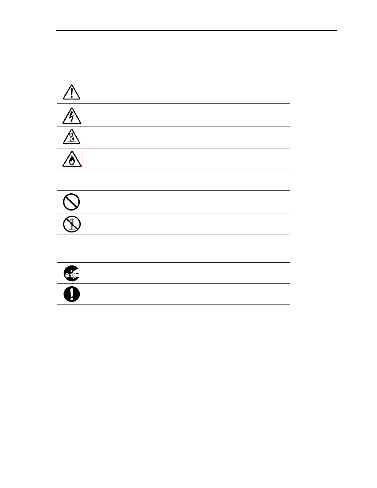
Attention
This symbol indicates a hazard.
An image in the symbol illustrates the hazard type.
(Example)
Precaution against
electric shock
Prohibited
Action
This symbol indicates prohibited actions. An image
in the symbol illustrates a particular prohibited action.
(Example)
Prohibition of
disassembly
Mandatory
Action
This symbol indicates mandatory actions. An image
in the symbol illustrates a mandatory action to avoid
a particular hazard.
(Example)
Unplug the power cord!
Page 6
3
Symbols Used in This Manual and Warning Labels
Cautions
Indicates a general notice or warning that cannot be specifically identified.
Indicates that improper use may cause an electric shock.
Indicates that improper use may cause a personal injury.
Indicates that improper use may cause fumes or fire.
Prohibited Actions
Indicates a general prohibited action that cannot be specifically identified.
Do not disassemble, repair, or modify the server. Doing so may cause an electric
shock or fire.
Mandatory Action
Unplug the power cord of the server. Not doing so may cause an electric shock or fire.
Indicates a mandatory action that cannot be specifically identified. Make sure to
follow the instruction.
Page 7

4
Safety Notes
Read the notes described below carefully to understand them, these will enable you to safely use your
product. See "Safety Indications" described earlier for the descriptions of symbols.
General
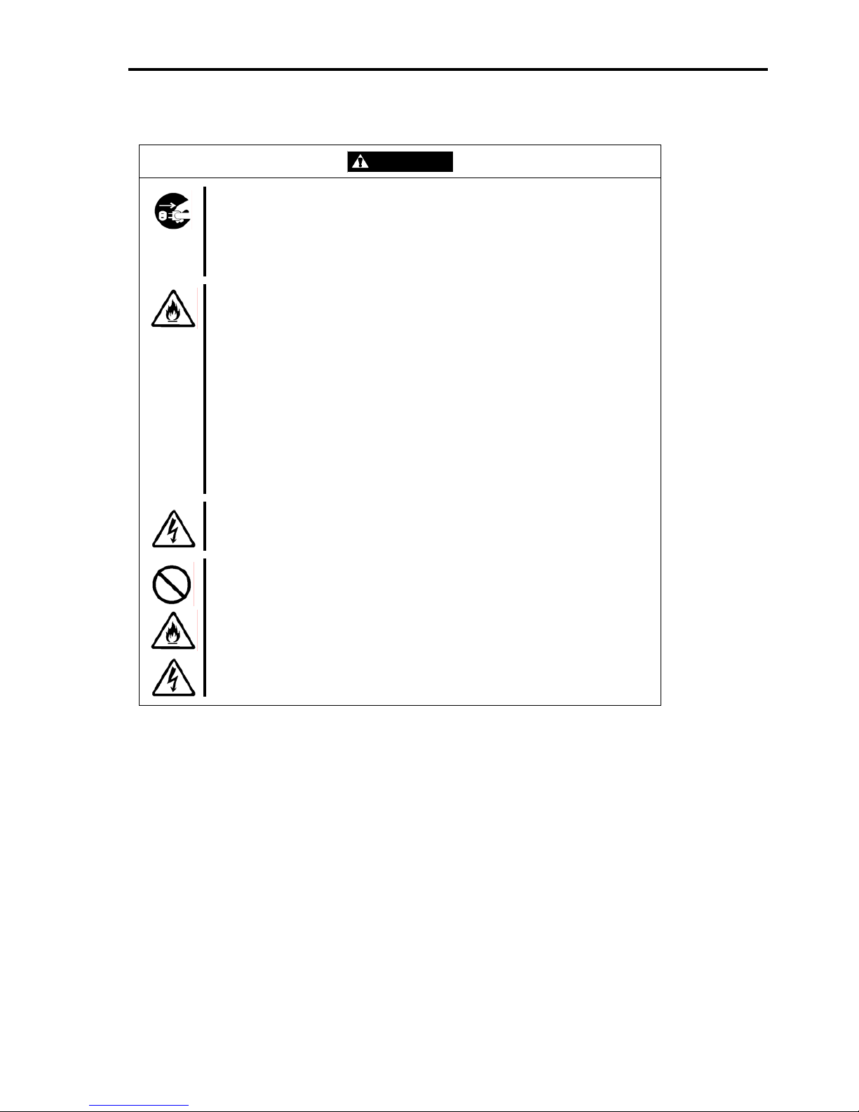
WARNING
Do not use the product for services involving human lives or requiring high
eliability.
r
The product is not intended to be used with or control facilities or devices
concerning human lives, including medical devices, nuclear facilities and devices,
aeronautics and space devices, transportation facilities and devices; and facilities
and devices requiring high reliability. The manufacturer assumes no liability for any
accident resulting in personal injury, death, or property damage if the Disk
Expansion Unit has been used in the above conditions.
Do not use the product if you are aware of any suspect smoke, odour, or
oise.
n
If smoke, odour, or noise is present, immediately switch off the unit and disconnect
the power plug from the outlet. Contact your sales agent. Using the product in
such conditions may cause a fire.
Keep needles or metal objects away from the server.
Do not insert needles or metal objects into the ventilation holes or cartridge slot of
the server. Doing so may cause an electric shock.
Keep water or foreign matter away from the server.
Do not let any form of liquid (water etc.) or foreign matter (e.g., pins or paper clips)
enter the server. Failure to follow this warning may cause an electric shock, a fire, or
a failure of the server. When such things accidentally enter the server, immediately
turn off the power and disconnect the power plug from the AC outlet. Do not
disassemble the server. Contact your service representative.
Page 8
5
Power Supply and Power Cord Use
CAUTION
Disconnect the power cord(s) before installing or removing the product
in/from the server.
Make sure to power off the server and disconnect the power cord(s) from the power
outlet before installing/removing the product in/from the server, or connecting with
the peripheral devices. All voltage is removed only when the power cords are
unplugged.
Always observe the following to prevent an electric shock or fire that could be
aused by a damaged cord.
c
Do not stretch the cord harness.
Do not pinch the power cord.
Do not bend the power cord.
Keep chemicals away from the power cord.
Do not twist the power cord.
Do not place any object on the power cord.
Do not bundle power cords.
Do not alter, modify, or repair the power cord.
Do not secure the power cord with staples or equivalents.
Do not use a damaged power cord. (Replace a damaged power cord with a
new one of the same specifications. Ask your sales agent for replacement.)
Do not hold the power plug if your hands are wet.
Do not disconnect/connect the plug while your hands are wet. Failure to follow this
warning may cause an electric shock.
Do not pull the cable when disconnecting the power cord.
When disconnecting the power cord from the server, hold the plug and pull it straight
out. Pulling the cord out by the cable portion could damage the cable to result in an
electrical shock hazard or a fire.
Page 9

6
Installation, Relocation, Storage, and Connection
CAUTION
Do not connect any interface cable when the power cord of the Disk
Expansion Unit is plugged to a power source.
Make sure to power off the server and unplug the power cord from a power outlet
before connecting/disconnecting the interface cable. If the server is off-powered but
its power cord is plugged to a power source, touching the cable may cause an
electric shock or a fire may result from a short circuit. Also, connect/disconnect the
interface cable after turning off the power of the destination.
Do not use any unauthorized interface cable.
Use only interface cables authorized by the manufacturer and locate a proper
device and connector before connecting a cable. Using an unauthorized cable or
connecting a cable to an improper destination may cause a short circuit, resulting in
a fire.
Also, observe the following notes on using and connecting an interface cable.
Do not step on the cable.
Do not place any object on the cable.
Do not use the server with loose cable connections.
Do not use any damaged cable connector.
Make sure the cable is securely locked with the relevant screws.
Do not use or store the product in the place where corrosive gases exist.
Make sure not to locate or use the server in the place where corrosive gases
(sulphur dioxide, hydrogen sulphide, nitrogen dioxide, chlorine, ammonia, ozone,
etc) exist.
Also, do not set it in the environment where the air (or dust) includes components
accelerating corrosion (ex. sulphur, sodium chloride) or conductive metals. There is
a risk of a fire due to corrosion and/or short-circuits of an internal printed board.
Avoid installation in extreme temperature conditions.
Immediately after the server is powered off, its internal components such as hard
disk drives are very hot. Let the installed components fully cool down before
installing/removing anything.
Page 10

7
Cleaning and Working with the Product
WARNING
Do not disassemble, repair, or alter the server.
Do not attempt to disassemble, repair, or alter the product in any occasion other
than those described in this User's Guide. Failure to follow this instruction may
cause an electric shock or fire as well as malfunctions of the product.
Disconnect the power plug before accessing inside the server.
Make sure to power off the server and disconnect the power plug from the AC outlet
before accessing inside the server. Touching any internal device of the server when
its power cord connected to a power source may cause an electric shock even if the
server is off-powered.
CAUTION
Make sure to complete installation.
Always connect the DC cable and/or interface cable firmly. An incompletely
onnected cable may cause a contact failure, resulting in smoke or fire.
c
During Operation
CAUTION
Avoid contact with the server during thunderstorms.
Disconnect the power plug from the outlet when a thunderstorm is approaching.
If the thunderstorm begins before you can disconnect the power plug, do not touch
any part of the server containing the product. Failure to follow this warning may
cause an electric shock.
Keep animals away from the server.
Do not use a cellular phone or a pager around the server.
Turn off cellular phones or pagers near the server containing the product. Radio
interference may cause malfunctions of the server.
Page 11

8
Warning Labels
Warning labels are attached to the product to inform the user that a hazardous situation may arise when
operating the chassis (do not take off any label or soil it). If you find any label unattached, almost peeled off,
or soiled, making the warning illegible, contact your sales agent.
Notes on Use - For correct operation of the BBU -
Note the following when you use the BBU. If you ignore these notes, your assets (including important data
and/or other devices) may be damaged.
The BBU is an additional battery exclusively designed for the Disk Array Controller (SAS) for which
you purchased it. It cannot be connected to any other disk array controllers.
The BBU is an extremely sensitive electronic device. Take all the necessary precautions to avoid
electro-static damages before handling the BBU.
Do not drop the BBU. Do not hit the BBU against other objects.
To recycle or dispose of the BBU, refer to "Recycling and Disposal" in this chapter.
Page 12

9
This Manual
The guide is intended for persons who are familiar with operating systems, including Windows, and
fundamental operations of general-purpose I/O devices, including the keyboard and mouse.
Text Conventions
The following conventions are used throughout this User's Guide. For safety symbols, see "SAFETY
INDICATIONS" provided earlier.
Notice
Items to be observed or points to be noted when operating the
product.
Check
Items to be checked when operating the product.
Tips
Information useful or convenient for you.
In the Package
Check the package contents.
The package contains various ac cessories, as well as the product itself. Check with the packing list and
make sure you have everything and that individual components are not damaged. If you find any missing or
damaged components, contact your sales agent.
Transportation
To transport the BBU, remove it from the server as described in "Chapter 1 Overvie w" and p ut the BBU and
all the accessories in the package used for the delivery.
Page 13

10
Third Party Transfer
Make sure to provide this manual along with the product to a third party.
Notice
About data on the hard disk
Be sure to take appropriate measures not to leak important data (e.g., customers'
information or companies' management information) on the removed hard disk to
any third parties.
Data seems to be erased when you empty "Recycle Bin" of Windows or execute
the "format" command of the operating system. However, the actual data remains
written on the hard disk. Data not erased completely may be restored by special
software and used for unexpected purposes.
It is strongly recommended that the software or service (both available at stores)
for data erasure should be used in order to avoid the trouble explained above. F or
details on data erasure, ask your sales representative.
The manufacturer assumes no liability for data leakage if the product is transferred
to third party without erasing the data.
To transfer or sell any software ap plication that comes with the product to a third party , the following
requirements must be satisfied:
¾ Transfer all the provided software applications, and keep no backup copies.
¾ Uninstall software applications before transferring the product.
Recycling and Disposal
The battery pack of the BBU is equipped with a recyclable lithium ion battery. To enable such valuable
resources to be reused, contact your service representative or bring it to the nearest recycle agent.
For the removal of the BBU, see "4. Battery Pack Replacement Procedure" in "Chapter 3 Operation and
Maintenance."
Dispose of other devices according to all national laws and regulations. For more information, contact the
local government or your service representative.
Take sufficient note on the handli ng of the battery pack following "Chapter 3 Operation and Maintenance."
Notice
It is the user's responsibility to completely erase or modify all the data
stored in storage device such as hard disk, backup data cartridge,
floppy disk, or any other media (CD-R/CD-RW) so that the data
cannot be restored.
Page 14

11
Contents
Preface ........................................................................................................................................1
NOTES ON USE - Always read the Notes -....................................................................2
Symbols Used in This Manual and Warning Labels.....................................................................3
Safety Notes................................................................................................................................4
Warning Labels............................................................................................................................8
Notes on Use - For correct operation of the BBU -......................................................................8
This Manual.................................................................................................................................9
In the Package.............................................................................................................................9
Transportation..............................................................................................................................9
Third Party Transfer...................................................................................................................10
Recycling and Disposal .............................................................................................................10
Contents ....................................................................................................................................11
Chapter 1 Overview..............................................................................................................12
1. BBU Characteristics...................................................................................................................12
2. Specifications.............................................................................................................................12
3. Installation Flow .........................................................................................................................13
4. Checking the Contents in the Package ......................................................................................13
5. Names and Functions of Sections..............................................................................................14
6. Installation Notes........................................................................................................................15
Chapter 2 Installing the BBU................................................................................................16
1. Installation Procedure.................................................................................................................16
1-1. Checking the Cable ............................................................................................................16
1-2. Putting Setup Date Label....................................................................................................17
1-3. Installing the BBU in the Disk Array Controller....................................................................17
1-4. Connecting the Cable.........................................................................................................18
2. Utility Check...............................................................................................................................19
Chapter 3 Operation and Maintenance................................................................................22
1. Maintenance Service..................................................................................................................22
2. Preventive Maintenance.............................................................................................................22
2-1. Preventive Maintenance of BBU.........................................................................................22
2-2. BBU Life .............................................................................................................................22
3. BBU Replacement Procedure....................................................................................................23
Page 15

Chapter 1 Overview
Read this chapter if you use the Additional DAC Battery (called BBU below) for the first time.
This chapter describes the characteristics and configuration of the BBU, and outlines the additional battery
installation job.
1. BBU Characteristics
The BBU is an additional battery exclusively used for the Disk Array Controller (SAS).
Connecting the BBU to the disk array controller can prevent data from being lost due to an unforeseen
accident, including instantaneous p ower interruption (in the WriteBack mode).
Backup (up to 72 hours ) of the data in the disk array controller cache memory.
Improvement of reliability in WriteBack mode.
Use of rechargeable NiMH battery.
2. Specifications
Item Specifications Remarks
Maximum data backup time 72 hours Full charge
Outer dimension (mm) 39 (width) × 133 (depth) × 9 (height)
Weight About 0.10 kg
Battery capacity 4.22 Wh Normal operation
Temperature
10°C - 35°C
Operating
environment
Humidity 20% - 80% Without condensation
Temperature
0°C - 35°C
Storage
environment
Humidity 20% - 80% Without condensation
Life (battery back) About 2 years
Varies depending on the
operating environment and
the boundary conditions
Page 16

13
3. Installation Flow
The following shows the BBU installation flow. For more information, refer to the corresponding chapters.
Start
Check BBU and accessories.
Check notes.
Install BBU.
Check and set connections.
End
Chapter 1
Describes how to check the BBU and
the included accessories as well as
installation notes.
Chapter 2
2. Utility Check
Describes the connection checking
procedure after the battery installation
and the setting of the write cache
mode.
Chapter 2
1. Installation Procedure
Describes how to install the BBU.
4. Checking the Contents in the Package
The package contains the following items. Check the contents to confirm you have all the necessary items
before starting the installation job.
No. Item Qty Remarks
1 Additional DAC battery 1 This unit
2 User Guide 1 This manual
3 Setup date label 1
The package contains the following items.
Battery Backup Unit (BBU)
Setup Date label
Page 17

14
5. Names and Functions of Sections
This section describes the sections of the BBU.
Front view
3
1 4
5
2 6
1
Battery cell
NiMH battery cell
2
Battery cable
Used to connect the battery cell to the memory module.
3
Memory connector
Insert the connector into the memory slot of the disk array controller.
4
Recycle and caution label
This label is stuck on the battery pack. It displays
warning messages, the battery type and the recycle
symbol.
5
Memory
Memory module connected to the battery cell.
Page 18

15
Rear view Accessories
7
Setup Date label (accessory)
The label comes with the BBU. Fill in the year and month when you install the BBU in the
disk array controller. Stick the label on the BBU surface for future reference.
6. Installation Notes
Do not lay the BBU on a metallic plate, including the chassis of the server.
Do not hold the BBU if your hands are wet.
Failure to follow these recommendations could cause a short-circuit on the battery.
Page 19

16
Chapter 2 Installing the BBU
This chapter describes the installation of the BBU in the disk array controller.
Check
The procedure described here is the installation of the BBU in the Internal
SAS HDD Disk Array Controller.
It is similar to the installation of the BBU in the External SAS HDD Disk
Array Controller.
1. Installation Procedure
Install the BBU in the disk array controller as described in the following procedure.
Check
Before starting the installation job, refer to the User Guides of the disk array
controller and of the server.
1-1. Checking the Cable
Make sure that the cable is removed from both the battery cell and the memory module.
If the cable is connected, remove it.
Page 20

17
1-2. Putting Setup Date Label
Fill in the year and month corresponding to the BBU installation date on the battery label coming with the
BBU. Stick the label on the BBU surface.
Fill in the year and month.
Example) Y 2005. M 12
Notice
The battery life is about 2 years and varies depending on the environment
of use and operating conditions. If the battery pack is used for more than 2
years, we cannot guarantee that the maximum data backup time (72 hours)
can still be achieved. Replace the battery pack as described in "Chapter 3
Operation and Maintenance."
1-3. Installing the BBU in the Disk Array Controller
Install the BBU in the disk array controller as described in the following procedure:
1. Open the lever securing the memory module of the disk array controller.
2. Remove the memory module from the disk array controller.
3. Insert securely the BBU into the slot.
4. Close the lever that was opened in Step 1 to fix the BBU.
Disk array controller
Memory (256 MB DIMM-II)
BBU
Page 21

18
1-4. Connecting the Cable
Connect the cable to the battery cell and the memory module.
Page 22

19
2. Utility Check
After the installation, check the connections and the settings of the BBU using the disk array controller
management utility "MegaRAID Storage Mana ger
TM
" (called MSM hereafter).
1. Boot the OS and start MSM.
2. Make sure that the "Battery Backup Unit" icon appears in the Physical tab of MSM.
Physical
"Battery Backup Unit" icon
3. Select the Logical tab in the left frame of the window, and then select each "Virtual Disk" un der the
Logical tab.
4. Select the Properties tab in the right frame of the window, and confirm the setting for Default Write
Policy.
Logical
Properties
Default Write Policy
Current Write Policy
Page 23

20
5. Change the Default Write Policy to "Write Back" if not specified.
6. To change the Default Write Policy:
6-1. Select the Logical tab in the left frame of the window, and then select each "Virtual Disk" under
the Logical tab.
6-2. Select the Set Virtual Disk Properties under the Operations tab in the right frame of the
window, and change the Default Write Policy to Write Back.
6-3. Repeat Steps 6-1 and 6-2 for all Virtual Disk under the Logical tab to change their Default
Write Policy to "Write Back".
Logical
Operations
Set Virtual Disk Properties
Default Write Policy
Page 24

21
7. Charge the BBU, and make sure that the Current Write Policy (indicating write cache operation
status) is indicated as "Write Back."
Logical
Properties
Default Write Policy
Current Write Policy
Notice
The battery cell you have purchased is not charged at all. In this case,
the [Current Write Policy] in the [Properties] of the [Logical] tab is
indicated as "Write Through" on MSM.
You can check the charge status of the battery cell by selecting [Relative
State of Charge] or [Absolute State of Charge] in [Physical] tab →
[Properties] on MSM.
If you changed the Write Policy from [Write Through] to [Write Back],
MSM displays the correct message, but the Windows Event Log
(application) indicates that the change was made contrarily.
Tips
For more information on the Write Policy, refer to the disk array controller
User Guide or to the MSM User Guide (online documentation included on
the CD-ROM shipped with the server).
Page 25

22
Chapter 3 Operation and Maintenance
1. Maintenance Service
We recommend you ask our Service Representatives for the help of one of our technici ans when your BBU
requires servicing. They will provide you with genuine parts, and you can rely on their high technical
capabilities.
2. Preventive Maintenance
2-1. Preventive Maintenance of BBU
We recommend your regularly check the BBU status (including voltage and temperature) as a preventive
maintenance. You can use MegaRAID Storage Manager™ (MSM) to do so.
2-2. BBU Life
The BBU is equipped with a backup battery. The battery life is about 2 years, and varies depending on the
environment of use and operating conditions.
Replace the battery with a new one after about two years starting from the in stallation of the BBU (refer to
the battery label put on the server and the BBU). Contact your service representative for the replacement or
follow the instructions in "3. BBU Replacement Procedure".
Notice
The BBU is a supply/charged warranty device.
Page 26

23
3. BBU Replacement Procedure
Replace the BBU as described in the following procedure:
Check
The procedure described here is the replacement of the BBU in the Internal
SAS HDD Disk Array Controller.
It is similar to the replacement of the BBU in the External SAS HDD Disk
Array Controller.
1. Fill in the year and month of replacement on the Setup Date label that comes with the new BBU,
and stick the label on the BBU surface. (See Section 1-2 for details.). Remove a ny existing Setup
Date label, or make sure to stick the latest on top of the others.
Fill the year and month.
Example) Y 2005. M 12
2. Exit from all applications and shut down the OS.
3. Power off the server and remove all the power cords connected to the power unit from the
receptacles.
4. Remove the side cover as described in the server User Guide.
5. Disconnect all the cables from the disk array controller.
6. Remove the disk array controller from the server.
7. Open the lever of the disk array controller to release the BBU.
8. Remove the BBU.
9. Insert the new BBU into the slot.
Page 27

24
10. Close the lever that was opened in Step 7 to secure the BBU.
Disk array controller
7
Old BBU
New BBU
11. Reinstall the disk array controller in the PCI (PCI Express) slot of the server, and secure it with
screws.
12. Reconnect all the cables to the disk array controller.
13. Replace the side cover and plug the power cords. Power on the server.
14. Once the OS has booted, check whether the BBU is recognized correctly. Refer to "2. Utility Check"
in "Chapter 2 Installing the BBU."
Notice
The battery cell you have purchased is not charged at all. In this case,
the [Current Write Policy] in the [Properties] of the [Logical] tab is
indicated as "Write Through" on MSM.
You can check the charge status of the battery cell by selecting [Relative
State of Charge] or [Absolute State of Charge] in [Physical] tab →
[Properties] on MSM.
Check
The battery cell is recyclable. Contact your service representative for proper
disposal.
Page 28

This page is deliberately left empty.
Page 29

 Loading...