

Page 1

Caller ID Handsfree Business Telephone
AT-35
U
SER GUIDE
DISCLAIMER
The material contained herein is subject to change without prior
notice at the sole discretion of NEC Business Solutions Ltd.
NEC Business Solutions Ltd.
Page 2

TABLE OF CONTENTS
IMPORTANT SAFETY INSTRUCTIONS................................................... 2
LOCATION OF CONTROLS...................................................................... 3
INSTALLATION ......................................................................................... 5
Package Contents
Installing the Batteries
Connecting the Telephone
Connecting an Additional Device
Wall Mounting
INITIAL SETUP.......................................................................................... 8
Selecting the Dialling Mode
Setting the LCD Contrast
Selecting the Ringing Volume
Selecting the Ringing Tone
Setting the Clock
Setting the Flash Time
Setting the PBX DIAL Code
BASIC OPERATION................................................................................ 10
Making a Call using the Handset
Making a Call using Speakerphone
Receiving a Call using the Handset
Receiving a Call using Speakerphone
Switching between Handset and Speakerphone
FEATURES.............................................................................................. 12
FLASH Key
PAUSE Key
Last Number Redial
Memory Redial
Microphone Mute
Message Waiting Lamp
Temporarily Switching Pulse to Tone Dialling
Call Hold
One-Touch Dialling
Caller ID (CLI)
TROUBLESHOOTING............................................................................. 17
Troubleshooting Guide
Care and Maintenance
SPECIFICATIONS................................................................................... 18
QUICK REFERENCE .............................................................................. 19
1
Page 3

IMPORTANT SAFETY INSTRUCTIONS
When using your telephone equipment, basic safety precautions
should always be followed to reduce the risk of fire, electric shock,
and injury to persons, by doing the following:
1. Read and understand all instructions.
2. Follow all warnings and instructions marked on the product.
3. Do not use this product near water, for example, near a bathtub, wash
bowl, kitchen sink, or laundry tub, in a wet basement, or near a
swimming pool.
4. Do not place this product on an unstable cart, stand, or table. The
product may fall, causing serious damage to the product.
5. Slots and openings in the cabinet and the back or bottom are provided
for ventilation. To protect it from overheating, these openings must not
be blocked or covered. The openings should never be blocked by
placing the product on a bed, sofa, rug, or other similar surface. This
product should never be placed near or over a radiator or heat register.
This product should not be placed in a built-in installation unless proper
ventilation is provided.
6. Never push objects of any kind into this product through cabinet slots as
they may touch dangerous voltage points or short out parts that could
result in a risk of fire, electric shock, or damage to the product itself.
Never spill liquid of any kind on the product.
7. To reduce the risk of electric shock, do not disassemble this product.
The product should be taken to a qualified service agent if service or
repair work is required. Opening or removing covers may expose you to
dangerous voltages or other risks. Incorrect reassembly can cause
electric shock when the product is subsequently used.
8. Avoid using a telephone during an electrical storm. There may be a
remote risk of electric shock from lightning.
9. Do not use the telephone to report a gas leak in the vicinity of the leak.
10. Please keep this unit away from equipment that uses radio waves or
microwaves, (e.g. a portable radio or microwave oven). These may
cause improper operation.
11. T he maximum level setting for the Receive Volume Control should
only be used by hearing impaired individuals, otherwise hearing
damage may occur.
2
Page 4
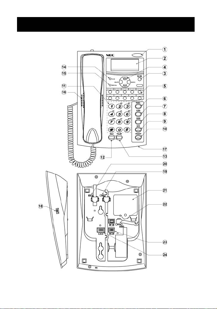
LOCATION OF CONTROLS
3
Page 5

LOCATION OF CONTROLS
1. Visual Ring Indicator/
Message Waiting Lamp
Flashes to indicate an incoming
call. May also indicate messages
have been received on some
PBX systems.
2. LCD Display
3. SET TIME / PBX DIAL Key
Used to enter clock setting mode
and for Dialling behind a PBX.
4. Multi-function Key
Provides the SEARCH, DELETE,
UP and DOWN keys for Memory
Dialling and reviewing Caller ID.
5. 10 One-Touch Keys
10 One-Touch dial memory keys
for fast redialling of numbers
stored in the memory.
6. REDIAL Key
Used for redialling the last
number you dialled.
7. FLASH Key
Used to disconnect the line and
retrieve it, or to access special
network functions.
8. PAUSE Key
Used to provide the pause digit
required by many PBX systems.
9. MUTE Key
Temporally switches off the
handset and speakerphone
microphone.
10. SPEAKER Key
Enables you to make or answer a
call, converse and hang-up
without lifting the handset.
11 . D i al K e ys
Dial keys on telephone keypad,
including ½ and #.
12. HOLD Key
Enables you to put your call on
hold.
13. VOLUME Key
Adjust the volume of the built-in
speaker.
14. IN USE LED
Used to indicate the telephone is
in use.
15. NEW CALL LED
Used to indicate the CLI number
displayed on the LCD is a new
call.
16. Speaker
Enables you to monitor your call
and to listen to the other party
when using the speakerphone
.
feature
17. Microphone
Picks up your voice when using
the Speakerphone feature
.
18. Handset Volume Control
Adjusts the volume of the
handset.
19. Line Socket
Used to connect with your local
telephone network.
20. Data Socket
Used for the parallel connection
of other analogue devices.
21. Battery Compartment
Requires 3 AA batteries.
22. Handset Socket
23. Dialling Mode Switch
Sets the dialling mode of the
telephone (DTMF or DP).
24. Ringing Volume Switch
Sets the volume of the ringer.
4
Page 6
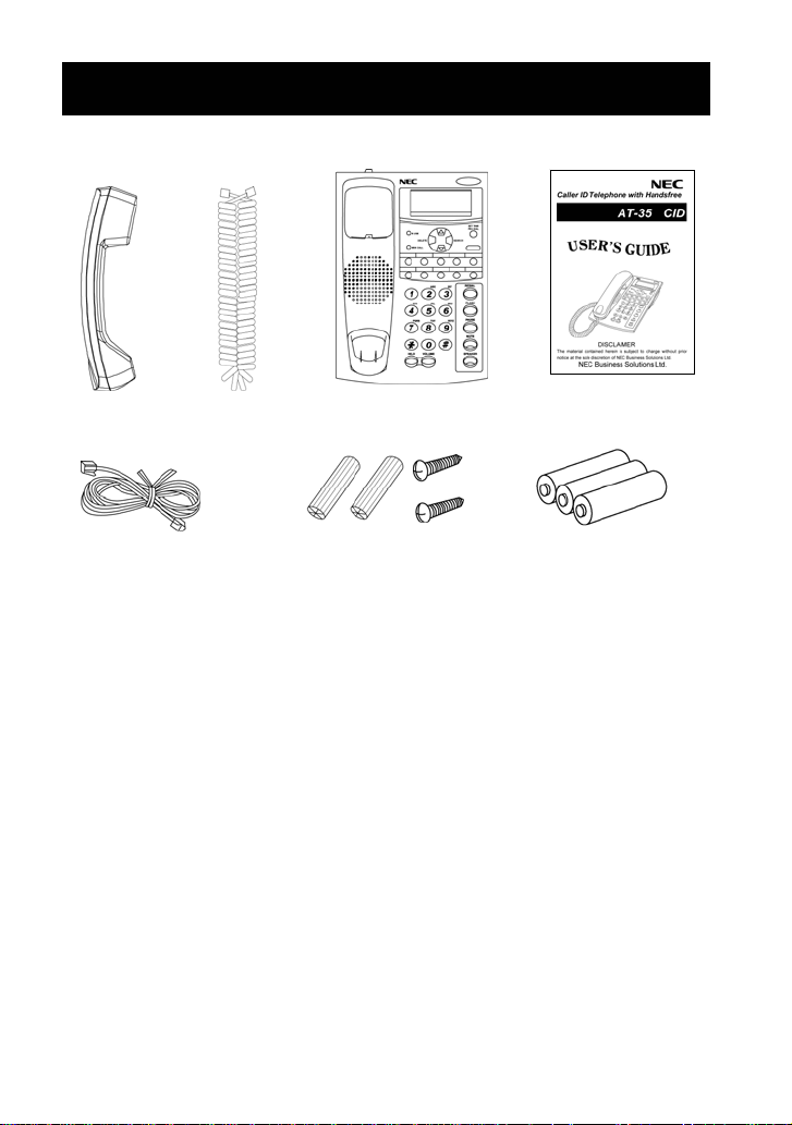
INSTALLATION
Package Contents
Handset Telephone Base This User’s Guide
Telephone Line Cord
Installing the Batteries
Install three high quality AA size Alkaline (LR6) or Manganese (R6,UM-3)
batteries. We recommend the use of Alkaline batteries.
Battery life: - approx. ten (10) months using Alkaline batteries.
- approx. five (5) months using Manganese batteries.
Battery life may depend on operating conditions and ambient temperature.
Three batteries are supplied for initial operation and testing. Please
replace these for new batteries for continued operation.
1. Loosen the screw on the battery compartment cover.
2. Open the battery compartment cover.
3. Insert three 1.5v AA batteries.
4. Close the compartment cover and secure the screw.
Handset Curly
Cord
Wall-Mount Screws
and Anchors
Three AA Batteries
(For initial operation test)
5
Page 7

INSTALLATION
IMPORTANT:
• Disconnect telephone line cord before removing battery cover to
replace the batteries. Battery cover must be in place at all other times.
• Replace all batteries every six (6) months.
• When the low battery indicator appears on the LCD, replace all
batteries immediately.
• To retain information stored in memor y, replace batteries within one (1)
minute.
• Use only new batteries of the specified size and type.
• Never mix new and old batteries.
• Use of alkaline batteries is recommended.
• Do not use nickel-cadmium batteries.
Battery Safety Precautions:
For your safety, please observe these precautions:
• Do not recharge, disassemble, mutilate, wet or incinerate batteries.
• Keep batteries out of reach of children.
• Use batteries of the same type; do not mix different type of batteries.
• Remove dead batteries from the telephone set immediately.
Connecting the Telephone
1. Connect one end of the handset cord with the short cord to the handset
jack, connect the other end with the long cord to the HANDSET socket
on the rear of the telephone.
2. Fit one end of the line cord to the LINE socket on the rear of telephone
and the other end to your telephone network outlet.
3. Lay the handset cord in the groove on the bottom of the telephone.
For best speakerphone performance, avoid the following:
• Areas with high background noise. (The microphone might pick up
these sounds and prevent the speakerphone from going into receiving
mode when you finish talking.)
• Surfaces affected by vibration.
• Recess ed areas such as in a corner, inside a cupboard, or next to a
cabinet, which can generate an echo effect.
6
Page 8

INSTALLATION
Connecting an Additional Device
An additional analogue device, such as an answering machine, facsimile
machine or PC modem can be connected in parallel with this telephone.
Connect one end of the line cord to the DATA socket on the rear of the
telephone and the other end to the LINE socket on the additional device.
Wall Mounting
This telephone set can be mounted on a wall with two screws (included).
1. Mark off the correct positions for the screws, 83.5mm apart vertically
opposed before drilling the wall as shown in Fig.1.
2. Install the screws into the wall.
3. Mount the telephone on the wall so that the screw heads insert into the
slots on the underside of the telephone set as shown in Fig.2.
Screws
If you wish to temporarily place the handset
down during a conversation, hook the
handset onto the top of the telephone set as
shown in Fig.3.
7
Page 9

INITIAL SETUP
Selecting the Dialling Mode
Set the dialling mode switch to either DP (Pulse) or MF (Tone) to select the
signalling type. The correct mode depends on the requirements of the
PBX to which the telephone is connected.
Setting the LCD Contrast
There are 5 display contrast settings.
1. Ensure the phone is idle.
2. Press VOLUME repeatedly to
set the desired LCD contrast.
Selecting the Ringing Volume
Select from three ringing volume levels using the Ringing Volume Switch,
L (low), M (mid), or H (high).
Selecting the Ringing Tone
There are 3 ringing tones to choose from – low, mid and high pitch.
1. Ensure the phone is idle.
2. Dial ¿ 1 ¿.
3. Dial 1 (low), 2 (mid) or 3 (high). (Default setting is 1.)
4. Dial #.
The selected ringing tone will play for approximately 2 seconds.
Setting the Clock
This telephone is equipped with a 24 hour clock. The clock is shown on
the display while the phone is idle. To set the clock, follow the step s below.
1. Ensure the phone is idle.
2. Hold the SET TIME button for approx. 2 seconds until the year appears
flashing on the display.
3.
Advance up or down to the correct year by pressing the or keys.
4.
Press the SET TIME button to set the year and advance to the Month.
5.
Repeat this process to set the Month, Date, Hour and Minute.
8
Page 10

INITIAL SETUP
Setting the Flash Time
The correct hookflash timing depends on the requirements of the PBX to
which the telephone is connected.
1. Ensure the phone is idle.
2. Dial ¿ 4 1 ¿.
3. Dial 00 to 06 to select from the following list of hookflash timings.
00: 95ms
01: 100ms (Default)
02: 120ms
03: 180ms
04: 270ms
05: 300ms
06: 600ms
4. Dial #.
Setting the PBX DIAL Code
When installed as a PBX extension, a trunk access code is often required
to precede external numbers that are dialled. The PBX DIAL key can
automatically insert the PBX trunk access code at the front of a dialled
number, when dialling from a One-Touch key, the IN List (Caller ID), or
when Preview Dialling.
The PBX trunk access code may differ from site to site, according to how
the PBX is configured. T o set the PBX DIAL code, follow the steps below.
To change the PBX DIAL code:
1. Ensure the phone is idle.
2. Dial ¿ 0 ¿.
3. Dial the PBX trunk access code 0 to 9. (Default=not assigned.)
4. Dial #.
To clear the PBX DIAL code:
1. Ensure the phone is idle.
2. Dial ¿ 0 ¿ #.
9
Page 11

BASIC OPERATION
Making a Call using the Handset
1. Pick up the handset and wait for dial tone.
2. Dial the number you require.
3. Replace the handset when you finish the call.
Or, to preview the dialled number:
1. Dial the number you require (while on-hook).
2. You may press the DELETE key to erase dialled digits one at a time.
3. When you have finished dialling, pick up the handset.
4. Replace the handset when you have finished the call.
Ö Adjust the volume if needed using the Handset Volume Control Switch.
Making a Call using Speakerphone
By using the SPEAKER key, you can make and receive calls without
picking up the handset. The speakerphone works in similar way to a
two-way radio; both parties cannot talk at the same time.
1. Press the SPEAKER key and wait for dial tone.
2. Dial the number you require.
3.
Once answered, converse in the normal way. Be sure to speak clearly
toward the microphone (located under the front edge of the phone).
4. To end the call, press the SPEAKER key .
Or, to preview the dialled number:
1. Dial the number you require (while on-hook).
2. You may press the DELETE key to erase dialled digits one at a time.
3. When you have finished dialling, press the SPEAKER key.
4.
Once answered, converse in the normal way. Be sure to speak clearly
toward the microphone (located under the front edge of the phone).
5. To end the call, press the SPEAKER key .
Ö Adjust the speaker volume if needed by pressing the VOLUME key.
10
Page 12

BASIC OPERATION
Receiving a Call using the Handset
1. Pick up the handset when the phone rings.
2. Converse with your caller.
3. Replace the handset when you finish the call.
Ö Adjust the volume if needed using the Handset Volume Control Switch.
Receiving a Call using Speakerphone
1. Press the SPEAKER key when the phone rings.
2. Converse with your caller.
3. To end the call, press the SPEAKER key.
Ö Adjust the speaker volume if needed by pressing the VOLUME key.
Switching between Handset and Speakerphone
You can switch between speakerphone and handset while dialling a
number, waiting for answer, or at anytime during a call.
To change from Handset to Speakerphone:
1. Press the SPEAKER Key.
2. Replace the handset.
To change from Speakerphone to Handset.
1. Pick up the handset.
11
Page 13

FEATURES
FLASH Key
The FLASH key works the same as the hook switch of the phone. When
the FLASH key is pressed during a conversation, it may terminate the call
or place the call on hold and you will hear dial tone allowing you to dial the
next phone number. T he FLASH key may also provide access to special
facilities such as call waiting and conference calls. Actual operation will
depend on the specific PBX to which you are connected.
To activate, press the FLASH key.
PAUSE Key
The PAUSE key is used to insert a 3.6 second pause between digits during
dialling. For automatic dialling (One-Touch Dial / Redial), the pause may
be needed in the dialling sequence to wait for the sound of a dial to ne or a
computer tone (such as computer activated operations like banking and
voice mail). A pause can be programmed into any memory location.
To activate, press the PAUSE key when required during dialling.
You may press the PAUSE key multiple times for a longer pause.
Last Number Redial
The last telephone number dialled (up to 32 digits) can be redialled
automatically by pressing the REDIAL key.
1. Pick up the handset (or press the SPEAKER key).
2. Press the REDIAL key.
You can re-dial the same telephone number as many times as required.
However, once you dial another number, the previous number is erased.
(Only the last number you dial will be stored under the REDIAL key).
12
Page 14

FEATURES
Memory Redial
The last 30 telephone numbers dialled (up to 21 digits each) are stored in
the Outgoing Call Memory. To dial from the Outgoing Call Memory:
1. Press the SEARCH key until the OUT icon is shown on the display.
2. Advance up or down to the ph one number you wish to dial by pressing
the or keys.
3. When the desired phone number is displayed, press the PBX DIAL key,
SPEAKER key, or lift the handset. Dialling starts automatically.
4. Press the DELETE key to remove the displayed number from the list.
Microphone Mute
The MUTE key switches off the handset and Speakerphone microphones,
so you can hear the other party, but they cannot hear you.
To Mute the call so that the outside party cannot hear you:
1. Press the MUTE key. The MUTE key LED will light up.
To cancel Mute and resume normal conversation:
1. Press the MUTE key. The MUTE LED will go out.
Message Waiting Lamp
Some PBX systems offer a visual message waiting system. The message
waiting lamp is turned on when there is a message left for you and flashes
while the phone is ringing to indicate an incoming call.
13
Page 15

FEATURES
Temporarily Switching Pulse to Tone Dialling
If your telephone set is connected to a Pulse dialling mode network, this
feature allows you to temporarily switch to Tone dialling to access Tone
operated services; e.g. answering machines, telephone banking, etc.
1. Dial the number of the service you wish to use and wait for answer.
2. Dial ¿ to sw itch to Tone dialling.
3. When you hang up, the phone automatically returns to Pulse dialling.
Call Hold
A call in progress may be placed on hold at the telephone by pressing the
HOLD key. It may also be possible to place the call on hold at the PBX
system by pressing the FLASH key. When the HOLD key is pressed, the
call remains on the telephone, during which time both parties hear the hold
melody until the call is retrieved.
Selecting the Hold Melody:
There are 2 different melodies for the HOLD function. To select the
desired melody, follow the procedure below.
1. Ensure the phone is idle.
2. Dial ¿ 5 ¿.
3. Dial 0 or 1 to select the desired melody. (Default = 0.)
4. Dial #.
Placing a Call on Hold:
1. With a conversation in progress on the phone.
2. Press the HOLD key.
3. If using the handset, you may put the handset back in the cradle.
4. To converse with the caller again, pick up the handset (or press the
SPEAKER key).
14
Page 16

FEATURES
One-Touch Dialling
This telephone set is equipped with 10 one-touch dial memory keys for
programming your most frequently dialled telephone numbers. You can
store up to 21 digits in each one-touch key. When using this telephone as
a PBX extension, you may need to include a Trunk Access Code followed
by a pause to gain an access to an outside line.
Index Label:
Surrounding the one-touch keys is an index label. When numbers are
entered into the one-touch keys, remove the plastic cover and make a note
against each key to remind you which number is stored in the memory.
To Store a Number under a One-Touch Key:
1. Ensure the phone is idle.
2. Dial the number you want to store (up to 21 digits).
This may include digits 0~9, ¿, # and Pause.
3. Press and hold the one-touch key (1-10) for approx. 2 seconds, until
you see “SAVE” shown on the display.
To Change the Number under a One-Touch Key:
Y ou can change a stored number by simply following the storage procedure
above. The new number will overwrite the previously stored number.
To Dial the Number under a One-Touch Key:
1. Press SPEAKER (or pick up the handset).
2. Press the desired one-touch key.
3. The stored number is automatically dialled out.
To Preview the Number before Dialling:
1. Press first the desired one-touch key. The stored number is displayed.
2. Press SPEAKER, PBX DIAL, or pick up the handset.
3. The stored number is automatically dialled out.
15
Page 17

FEATURES
Caller ID (CLI)
This telephone set will display Caller ID (CLI) information received with
incoming calls. The last 90 Caller ID numbers receive d are automatically
stored in CLI memory (up to 21 digits each). The numbers stored in CLI
memory may be reviewed, deleted, or dialled back if desired.
When a new call received with CLI goes unanswered, the NEW CALL light
will flash. The number of new (unanswered) calls received with CLI is
indicated on the bottom row of the display. Note that the oldest call in the
list occupies position 01 and new calls are stored at the end of the list.
When CLI is restricted by the caller, “NO CLI” is displayed.
For international and payphone calls, “OUT OF AREA” is displayed.
Date and Time Indicates viewing
Stamp for CLI. IN or OUT List.
NEW
The call was
unanswered.
REPEAT
Call received
more than one.
To Review the CLI Memory:
1. Press the SEARCH key until the “IN” icon is shown on the display.
2. Advance up or down to review received CLI numbers by pressing the
or keys. To view the most recent NEW CALL, press the key.
3. Press the DELETE key to remove the displayed number from the list.
To Dial Back from the CLI Memory:
1. Press the SEARCH key until the “IN” icon is shown on the display.
2. Advance up or down to the ph one number you wish to dial by pressing
the or key.
3. When the required phone number is displayed, press the PBX DIAL key,
SPEAKER key, or lift the handset. The number is automatically dialled.
Number of
calls in list.
Number of
new calls.
16
Page 18

TROUBLESHOOTING
Troubleshooting Guide
Problem Solution
No dial tone /
Will not dial out
Phone does not
ring
Cannot be heard by
the other party
Cannot use
one-touch dialling
No display on LCD
while phone is idle
Care and Maintenance
To keep your telepho ne set working well and looking good, follow these
few simple guidelines.
• Avoid putting the telephone near heating appliances and devices that
generate electrical noise.
• The telephone should not be exposed directly to sunlight or moisture.
• Avoid dropping the handset and other rough treatment.
• Clean the telephone using a soft cloth moistened with a mild cleaning
solution.
• Never use cleaners containing alcohol, strong cleaners that may
corrode plastic, or abrasive powders, as this may damage the finish.
Remove all traces of the cleaner with a damp cloth.
• Check that the hookswitch is not depressed.
• Check that the line cord is connected.
• Make sure the SPEAKER key LED is lit (if
using speakerphone).
• Ensure that the Dialling Mode Switch is set to
the correct position.
• Unplug the phone, wait 30 seconds, then plug
the phone back in.
• Disconnect any additional devices connected
to the DATA port.
• Ensure there are no other devices connected
to the same line.
• Confirm phone cord and handset curly cord
are securely plugged in.
• Make sure MUTE key LED is off.
• Make sure that a number has been correctly
stored under the one-touch key.
• A row of “-“ indicates an empty one-touch key.
• Check that batteries are fitted and that they
are in good condition.
17
Page 19

SPECIFICATIONS
Caller ID receiver FSK (type I) or DTMF
Caller ID information CLI number with date and
time stamp
Caller ID review, delete, dial back Yes
Caller ID storage 90 (21 digits)
Last number redial storage 30 (21 digits)
Last number redial key Yes (32 digits)
One-touch key memories 10 (21 digits each)
Date and time display Yes (24 hour)
Call duration timer Yes
Music on hold with selectable tones Yes (2 melodies)
DTMF and Decadic dialling Yes (DP/MF switch)
Selectable hook flash timing 95/100/120/180/300/600ms
(default=100ms)
Pause key Yes (3.6 sec)
Mute key (handset and handsfree) Yes (with LED indication)
Message waiting lamp Yes
Visual ring indicator Yes
In-use indication Yes
New call indication Yes (LED and LCD)
Repeat call indication Yes
Speakerphone (Handsfree) Yes (half duplex)
Speakerphone receive volume control Yes (8 levels)
Handset receive volume control Yes (slide switch, 3 levels)
Adjustable ring volume Yes (3 levels)
Adjustable ring tone Yes (3 pitches)
Data port (parallel connection) Yes
Battery for memory backup 3 x AA batteries
Low battery indication Yes
Automatic insertion of trunk access code Yes (selectable 0~9)
Adjustable LCD contrast Yes (5 levels)
Wall mountable Yes (in-built)
Telephone l ine interface 2-wire analogue centre pair
18
Page 20

QUICK REFERENCE
Feature Access Codes
Operation: Dial Access Code + Option Code + #
Feature Access Code Option Code
Ring Tone ¿ 1 ¿ 1: Low Tone
2: Mid Tone (default)
3: High Tone
Hold Tone ¿ 5 ¿ 0: Tone 1 (default)
1: Tone 2
PBX Trunk Access Code ¿ 0 ¿ 0~9
(default = 0)
Hook Flash Timing ¿ 41 ¿ 00: 95ms
01: 100ms (default)
02: 120ms
03: 180ms
04: 270ms
05: 300ms
06: 600ms
Reset CLI Receiving
Mode (FSK or DTMF)
Operations
Feature Operation Telephone State
LCD Contrast Press VOLUME Idle
Handsfree Volume Press VOLUME Off Hook Handsfree
Handset Volume Handset Volume
Mute Speakerphone Press MUTE Off Hook Handsfree
Mute Handset Press MUTE Off Hook Handset
Place Call On Hold Press HOLD Off Hook
Retrieve Call From Hold Press SPEAKER On Hold
¿ ¿ Mode set automatically
upon first call with CLI
Control Switch
NEC Business Solutions Ltd.
NEC-9182
Version 1.0
19
 Loading...