


Empowered by Innovation
Networking Manual
P/N 0893207
Rev 3, June 2006
Printed in U.S.A.
5.24
Technical Support Web Site:
http://ws1.necii.com (registration is required)

This manual has been developed by NEC Unified Solutions, Inc. It is intended for the use of its customers and
service personnel, and should be read in its entirety before attempting to install or program the system. Any
comments or suggestions for improving this manual would be appreciated. Forward your remarks to:
NEC Unified Solutions, Inc.
4 Forest Parkway
Shelton, CT 06484
necunifiedsolutions.com
Nothing contained in this manual shall be deemed to be, and this manual does not constitute, a warranty of, or
representation with respect to, any of the equipment covered. This manual is subject to change without notice and
NEC Unified Solutions, Inc. has no obligation to provide any updates or corrections to this manual. Further, NEC
Unified Solutions, Inc. also reserves the right, without prior notice, to make changes in equipment design or
components as it deems appropriate. No representation is made that this manual is complete or accurate in all
respects and NEC Unified Solutions, Inc. shall not be liable for any errors or omissions. In no event shall NEC Unified
Solutions, Inc. be liable for any incidental or consequential damages in connection with the use of this manual. This
document contains proprietary information that is protected by copyright. All rights are reserved. No part of this
document may be photocopied or reproduced without prior written consent of NEC Unified Solutions, Inc.
©2006 by NEC Unified Solutions, Inc. All Rights Reserved.
Printed in U.S.A.

◆
Introduction . . . . . . . . . . . . . . . . . . . . . . . . . . . . . . . . . . . . . . . . . . . . . . . . . . . . . . .1
About Aspire Networking . . . . . . . . . . . . . . . . . . . . . . . . . . . . . . . . . . . . . . . . . . . . . . . . 1
What is Networking? . . . . . . . . . . . . . . . . . . . . . . . . . . . . . . . . . . . . . . . . . . . . . . 1
Aspire Requirements . . . . . . . . . . . . . . . . . . . . . . . . . . . . . . . . . . . . . . . . . . . . . . 3
Available Features . . . . . . . . . . . . . . . . . . . . . . . . . . . . . . . . . . . . . . . . . . . . . . . . . . . . . 6
Available Features . . . . . . . . . . . . . . . . . . . . . . . . . . . . . . . . . . . . . . . . . . . . . . . . 6
About This Manual . . . . . . . . . . . . . . . . . . . . . . . . . . . . . . . . . . . . . . . . . . . . . . . . . . . . . 8
Using This Manual. . . . . . . . . . . . . . . . . . . . . . . . . . . . . . . . . . . . . . . . . . . . . . . . 8
Unique Considerations. . . . . . . . . . . . . . . . . . . . . . . . . . . . . . . . . . . . . . . . . . . . . 9
Setting Up The Networking Feature . . . . . . . . . . . . . . . . . . . . . . . . . . . . . . . . . . .11
Required System Programming . . . . . . . . . . . . . . . . . . . . . . . . . . . . . . . . . . . . . . . . . . 11
Basic System Programming. . . . . . . . . . . . . . . . . . . . . . . . . . . . . . . . . . . . . . . . 11
ISDN Networking . . . . . . . . . . . . . . . . . . . . . . . . . . . . . . . . . . . . . . . . . . . . . . . . . . . . . 12
IP Networking . . . . . . . . . . . . . . . . . . . . . . . . . . . . . . . . . . . . . . . . . . . . . . . . . . . . . . . . 16
Multi-Site Networking . . . . . . . . . . . . . . . . . . . . . . . . . . . . . . . . . . . . . . . . . . . . . . . . . . 31
Numbering Plan . . . . . . . . . . . . . . . . . . . . . . . . . . . . . . . . . . . . . . . . . . . . . . . . . . . . . . 32
Table of Contents
Features . . . . . . . . . . . . . . . . . . . . . . . . . . . . . . . . . . . . . . . . . . . . . . . . . . . . . . . . .37
911 Call Routing . . . . . . . . . . . . . . . . . . . . . . . . . . . . . . . . . . . . . . . . . . . . . . . . . . . . . . 39
911 Call Routing : Using ARS Class of Service Matching to Call
Local Authorities . . . . . . . . . . . . . . . . . . . . . . . . . . . . . . . . . . . . . . . . . . . . . . . . 39
ARS/F-Route . . . . . . . . . . . . . . . . . . . . . . . . . . . . . . . . . . . . . . . . . . . . . . . . . . . . . . . . . 40
BLF Indication . . . . . . . . . . . . . . . . . . . . . . . . . . . . . . . . . . . . . . . . . . . . . . . . . . . . . . . 46
Barge In . . . . . . . . . . . . . . . . . . . . . . . . . . . . . . . . . . . . . . . . . . . . . . . . . . . . . . . . . . . . 47
Call Forwarding . . . . . . . . . . . . . . . . . . . . . . . . . . . . . . . . . . . . . . . . . . . . . . . . . . . . . . 48
Call Forwarding / Do Not Disturb Override . . . . . . . . . . . . . . . . . . . . . . . . . . . . . . . . 50
Call Forward, Off-Premise . . . . . . . . . . . . . . . . . . . . . . . . . . . . . . . . . . . . . . . . . . . . . . 51
Call Forwarding with Follow Me . . . . . . . . . . . . . . . . . . . . . . . . . . . . . . . . . . . . . . . . . 52
Call Waiting / Camp On . . . . . . . . . . . . . . . . . . . . . . . . . . . . . . . . . . . . . . . . . . . . . . . . 53
Call Waiting / Camp On . . . . . . . . . . . . . . . . . . . . . . . . . . . . . . . . . . . . . . . . . . 53
Callback . . . . . . . . . . . . . . . . . . . . . . . . . . . . . . . . . . . . . . . . . . . . . . . . . . . . . . . 54
Caller ID Display . . . . . . . . . . . . . . . . . . . . . . . . . . . . . . . . . . . . . . . . . . . . . . . . . . . . . 56
Central Office Calls, Placing . . . . . . . . . . . . . . . . . . . . . . . . . . . . . . . . . . . . . . . . . . . . 57
Central Office Calls, Placing: Seizing a trunk in a networked system . . . . . . . 57
Channel Release Link . . . . . . . . . . . . . . . . . . . . . . . . . . . . . . . . . . . . . . . . . . . . . . . . . . 59
Conference . . . . . . . . . . . . . . . . . . . . . . . . . . . . . . . . . . . . . . . . . . . . . . . . . . . . . . . . . . 60
Department Calling . . . . . . . . . . . . . . . . . . . . . . . . . . . . . . . . . . . . . . . . . . . . . . . . . . . 62
Department Step Call . . . . . . . . . . . . . . . . . . . . . . . . . . . . . . . . . . . . . . . . . . . . . . . . . . 64
Direct Inward Dialing (DID) . . . . . . . . . . . . . . . . . . . . . . . . . . . . . . . . . . . . . . . . . . . . 65
Direct Inward Line (DIL) . . . . . . . . . . . . . . . . . . . . . . . . . . . . . . . . . . . . . . . . . . . . . . . 66
Direct Inward System Access (DISA) . . . . . . . . . . . . . . . . . . . . . . . . . . . . . . . . . . . . . . 67
Fax Over Networking . . . . . . . . . . . . . . . . . . . . . . . . . . . . . . . . . . . . . . . . . . . . . . . . . . 69
Aspire Networking Manual
Table of Contents- 1

Table of Contents
Hold . . . . . . . . . . . . . . . . . . . . . . . . . . . . . . . . . . . . . . . . . . . . . . . . . . . . . . . . . . . . . . . . 71
Hotline / Direct Station Selection (DSS) . . . . . . . . . . . . . . . . . . . . . . . . . . . . . . . . . . . . 72
Intercom . . . . . . . . . . . . . . . . . . . . . . . . . . . . . . . . . . . . . . . . . . . . . . . . . . . . . . . . . . . . 74
Keep Alive Operation . . . . . . . . . . . . . . . . . . . . . . . . . . . . . . . . . . . . . . . . . . . . . . . . . . 75
Last Number Redial . . . . . . . . . . . . . . . . . . . . . . . . . . . . . . . . . . . . . . . . . . . . . . . . . . . 76
Message Waiting . . . . . . . . . . . . . . . . . . . . . . . . . . . . . . . . . . . . . . . . . . . . . . . . . . . . . . 77
Operator, Centralized . . . . . . . . . . . . . . . . . . . . . . . . . . . . . . . . . . . . . . . . . . . . . . . . . . 78
Paging . . . . . . . . . . . . . . . . . . . . . . . . . . . . . . . . . . . . . . . . . . . . . . . . . . . . . . . . . . . . . . 79
Park . . . . . . . . . . . . . . . . . . . . . . . . . . . . . . . . . . . . . . . . . . . . . . . . . . . . . . . . . . . . . . . . 81
Ringdown Extension, Internal/External . . . . . . . . . . . . . . . . . . . . . . . . . . . . . . . . . . . . 83
Selectable Display Messaging . . . . . . . . . . . . . . . . . . . . . . . . . . . . . . . . . . . . . . . . . . . 84
Toll Restriction . . . . . . . . . . . . . . . . . . . . . . . . . . . . . . . . . . . . . . . . . . . . . . . . . . . . . . . 85
Transfer . . . . . . . . . . . . . . . . . . . . . . . . . . . . . . . . . . . . . . . . . . . . . . . . . . . . . . . . . . . . . 86
Voice Mail, Centralized . . . . . . . . . . . . . . . . . . . . . . . . . . . . . . . . . . . . . . . . . . . . . . . . 89
Voice Mail, Local . . . . . . . . . . . . . . . . . . . . . . . . . . . . . . . . . . . . . . . . . . . . . . . . . . . . . 93
Programming . . . . . . . . . . . . . . . . . . . . . . . . . . . . . . . . . . . . . . . . . . . . . . . . . . . . .99
Programming Basics . . . . . . . . . . . . . . . . . . . . . . . . . . . . . . . . . . . . . . . . . . . . . . . . . . 101
Before Reading This Section . . . . . . . . . . . . . . . . . . . . . . . . . . . . . . . . . . . . . . 101
How to Use This Section . . . . . . . . . . . . . . . . . . . . . . . . . . . . . . . . . . . . . . . . . 101
How to Enter the Programming Mode. . . . . . . . . . . . . . . . . . . . . . . . . . . . . . . 102
How to Exit the Programming Mode. . . . . . . . . . . . . . . . . . . . . . . . . . . . . . . . 103
Using Keys to Move Around in the Programs. . . . . . . . . . . . . . . . . . . . . . . . . 104
Programming Names and Text Messages . . . . . . . . . . . . . . . . . . . . . . . . . . . . 105
Programming Names and Text Messages . . . . . . . . . . . . . . . . . . . . . . . . . . . . 106
Using Soft Keys For Programming . . . . . . . . . . . . . . . . . . . . . . . . . . . . . . . . . 108
What the Soft Key Display Prompts Mean . . . . . . . . . . . . . . . . . . . . . . . . . . . 108
10-03 : PCB Setup . . . . . . . . . . . . . . . . . . . . . . . . . . . . . . . . . . . . . . . . . . . . . . . . . . . 109
Description. . . . . . . . . . . . . . . . . . . . . . . . . . . . . . . . . . . . . . . . . . . . . . . . . . . . 109
Feature Cross Reference . . . . . . . . . . . . . . . . . . . . . . . . . . . . . . . . . . . . . . . . . 118
Telephone Programming Instructions . . . . . . . . . . . . . . . . . . . . . . . . . . . . . . . 118
10-12 : NTCPU Network Setup . . . . . . . . . . . . . . . . . . . . . . . . . . . . . . . . . . . . . . . . . . 119
Description. . . . . . . . . . . . . . . . . . . . . . . . . . . . . . . . . . . . . . . . . . . . . . . . . . . . 119
Feature Cross Reference . . . . . . . . . . . . . . . . . . . . . . . . . . . . . . . . . . . . . . . . . 120
Telephone Programming Instructions . . . . . . . . . . . . . . . . . . . . . . . . . . . . . . . 121
10-20 : LAN Setup for External Equipment . . . . . . . . . . . . . . . . . . . . . . . . . . . . . . . . 122
Description. . . . . . . . . . . . . . . . . . . . . . . . . . . . . . . . . . . . . . . . . . . . . . . . . . . . 122
Feature Cross Reference . . . . . . . . . . . . . . . . . . . . . . . . . . . . . . . . . . . . . . . . . 122
Telephone Programming Instructions . . . . . . . . . . . . . . . . . . . . . . . . . . . . . . . 123
10-27 : IP System ID . . . . . . . . . . . . . . . . . . . . . . . . . . . . . . . . . . . . . . . . . . . . . . . . . . 124
Description. . . . . . . . . . . . . . . . . . . . . . . . . . . . . . . . . . . . . . . . . . . . . . . . . . . . 124
Feature Cross Reference . . . . . . . . . . . . . . . . . . . . . . . . . . . . . . . . . . . . . . . . . 124
Telephone Programming Instructions . . . . . . . . . . . . . . . . . . . . . . . . . . . . . . . 125
Table of Contents - 2 ◆
Aspire Networking Manual

◆
10-31 : Networking Keep Alive Setup . . . . . . . . . . . . . . . . . . . . . . . . . . . . . . . . . . . . . 126
Description. . . . . . . . . . . . . . . . . . . . . . . . . . . . . . . . . . . . . . . . . . . . . . . . . . . . 126
Feature Cross Reference . . . . . . . . . . . . . . . . . . . . . . . . . . . . . . . . . . . . . . . . . 126
Telephone Programming Instructions . . . . . . . . . . . . . . . . . . . . . . . . . . . . . . . 127
10-32 : PRI Networking Channel Limitation . . . . . . . . . . . . . . . . . . . . . . . . . . . . . . . 128
Description. . . . . . . . . . . . . . . . . . . . . . . . . . . . . . . . . . . . . . . . . . . . . . . . . . . . 128
Feature Cross Reference . . . . . . . . . . . . . . . . . . . . . . . . . . . . . . . . . . . . . . . . . 128
Telephone Programming Instructions . . . . . . . . . . . . . . . . . . . . . . . . . . . . . . . 129
11-01 : System Numbering . . . . . . . . . . . . . . . . . . . . . . . . . . . . . . . . . . . . . . . . . . . . . 130
Description. . . . . . . . . . . . . . . . . . . . . . . . . . . . . . . . . . . . . . . . . . . . . . . . . . . . 130
Feature Cross Reference . . . . . . . . . . . . . . . . . . . . . . . . . . . . . . . . . . . . . . . . . 139
Telephone Programming Instructions . . . . . . . . . . . . . . . . . . . . . . . . . . . . . . . 139
11-02 : Extension Numbering . . . . . . . . . . . . . . . . . . . . . . . . . . . . . . . . . . . . . . . . . . . 140
Description. . . . . . . . . . . . . . . . . . . . . . . . . . . . . . . . . . . . . . . . . . . . . . . . . . . . 140
Feature Cross Reference . . . . . . . . . . . . . . . . . . . . . . . . . . . . . . . . . . . . . . . . . 140
Telephone Programming Instructions . . . . . . . . . . . . . . . . . . . . . . . . . . . . . . . 141
11-07 : Department Group Pilot Numbers . . . . . . . . . . . . . . . . . . . . . . . . . . . . . . . . . 142
Description. . . . . . . . . . . . . . . . . . . . . . . . . . . . . . . . . . . . . . . . . . . . . . . . . . . . 142
Feature Cross Reference . . . . . . . . . . . . . . . . . . . . . . . . . . . . . . . . . . . . . . . . . 142
Telephone Programming Instructions . . . . . . . . . . . . . . . . . . . . . . . . . . . . . . . 143
11-10 : Service Code Setup (for System Administrator) . . . . . . . . . . . . . . . . . . . . . . . 144
Description. . . . . . . . . . . . . . . . . . . . . . . . . . . . . . . . . . . . . . . . . . . . . . . . . . . . 144
Feature Cross Reference . . . . . . . . . . . . . . . . . . . . . . . . . . . . . . . . . . . . . . . . . 146
Telephone Programming Instructions . . . . . . . . . . . . . . . . . . . . . . . . . . . . . . . 146
11-11 : Service Code Setup (for Setup/Entry Operation) . . . . . . . . . . . . . . . . . . . . . . 147
Description. . . . . . . . . . . . . . . . . . . . . . . . . . . . . . . . . . . . . . . . . . . . . . . . . . . . 147
Feature Cross Reference . . . . . . . . . . . . . . . . . . . . . . . . . . . . . . . . . . . . . . . . . 149
Telephone Programming Instructions . . . . . . . . . . . . . . . . . . . . . . . . . . . . . . . 150
11-12 : Service Code Setup (for Service Access) . . . . . . . . . . . . . . . . . . . . . . . . . . . . 151
Description. . . . . . . . . . . . . . . . . . . . . . . . . . . . . . . . . . . . . . . . . . . . . . . . . . . . 151
Feature Cross Reference . . . . . . . . . . . . . . . . . . . . . . . . . . . . . . . . . . . . . . . . . 154
Telephone Programming Instructions . . . . . . . . . . . . . . . . . . . . . . . . . . . . . . . 154
11-16 : Single Digit Service Code Setup . . . . . . . . . . . . . . . . . . . . . . . . . . . . . . . . . . . 155
Description. . . . . . . . . . . . . . . . . . . . . . . . . . . . . . . . . . . . . . . . . . . . . . . . . . . . 155
Feature Cross Reference . . . . . . . . . . . . . . . . . . . . . . . . . . . . . . . . . . . . . . . . . 156
Telephone Programming Instructions . . . . . . . . . . . . . . . . . . . . . . . . . . . . . . . 156
14-01 : Basic Trunk Data Setup . . . . . . . . . . . . . . . . . . . . . . . . . . . . . . . . . . . . . . . . . 157
Description. . . . . . . . . . . . . . . . . . . . . . . . . . . . . . . . . . . . . . . . . . . . . . . . . . . . 157
Feature Cross Reference . . . . . . . . . . . . . . . . . . . . . . . . . . . . . . . . . . . . . . . . . 160
Telephone Programming Instructions . . . . . . . . . . . . . . . . . . . . . . . . . . . . . . . 161
Table of Contents
Aspire Networking Manual
Table of Contents- 3

Table of Contents
14-06 : Trunk Group Routing . . . . . . . . . . . . . . . . . . . . . . . . . . . . . . . . . . . . . . . . . . . 162
Description. . . . . . . . . . . . . . . . . . . . . . . . . . . . . . . . . . . . . . . . . . . . . . . . . . . . 162
Feature Cross Reference . . . . . . . . . . . . . . . . . . . . . . . . . . . . . . . . . . . . . . . . . 163
Telephone Programming Instructions . . . . . . . . . . . . . . . . . . . . . . . . . . . . . . . 163
15-03 : Single Line Telephone Basic Data Setup . . . . . . . . . . . . . . . . . . . . . . . . . . . . 164
Description. . . . . . . . . . . . . . . . . . . . . . . . . . . . . . . . . . . . . . . . . . . . . . . . . . . . 164
Feature Cross Reference . . . . . . . . . . . . . . . . . . . . . . . . . . . . . . . . . . . . . . . . . 164
Telephone Programming Instructions . . . . . . . . . . . . . . . . . . . . . . . . . . . . . . . 165
16-01 : Department Group Basic Data Setup . . . . . . . . . . . . . . . . . . . . . . . . . . . . . . . 166
Description. . . . . . . . . . . . . . . . . . . . . . . . . . . . . . . . . . . . . . . . . . . . . . . . . . . . 166
Feature Cross Reference . . . . . . . . . . . . . . . . . . . . . . . . . . . . . . . . . . . . . . . . . 167
Telephone Programming Instructions . . . . . . . . . . . . . . . . . . . . . . . . . . . . . . . 168
16-02 : Department Group Assignment for Extensions . . . . . . . . . . . . . . . . . . . . . . . 169
Description. . . . . . . . . . . . . . . . . . . . . . . . . . . . . . . . . . . . . . . . . . . . . . . . . . . . 169
Feature Cross Reference . . . . . . . . . . . . . . . . . . . . . . . . . . . . . . . . . . . . . . . . . 169
Telephone Programming Instructions . . . . . . . . . . . . . . . . . . . . . . . . . . . . . . . 170
20-01 : System Options . . . . . . . . . . . . . . . . . . . . . . . . . . . . . . . . . . . . . . . . . . . . . . . . 171
Description. . . . . . . . . . . . . . . . . . . . . . . . . . . . . . . . . . . . . . . . . . . . . . . . . . . . 171
Feature Cross Reference . . . . . . . . . . . . . . . . . . . . . . . . . . . . . . . . . . . . . . . . . 171
Telephone Programming Instructions . . . . . . . . . . . . . . . . . . . . . . . . . . . . . . . 171
21-16 : Trunk Group Routing for Networks . . . . . . . . . . . . . . . . . . . . . . . . . . . . . . . . 172
Description. . . . . . . . . . . . . . . . . . . . . . . . . . . . . . . . . . . . . . . . . . . . . . . . . . . . 172
Feature Cross Reference . . . . . . . . . . . . . . . . . . . . . . . . . . . . . . . . . . . . . . . . . 172
Telephone Programming Instructions . . . . . . . . . . . . . . . . . . . . . . . . . . . . . . . 173
22-05 : Incoming Trunk Ring Group Assignment . . . . . . . . . . . . . . . . . . . . . . . . . . . . 174
Description. . . . . . . . . . . . . . . . . . . . . . . . . . . . . . . . . . . . . . . . . . . . . . . . . . . . 174
Feature Cross Reference . . . . . . . . . . . . . . . . . . . . . . . . . . . . . . . . . . . . . . . . . 174
Telephone Programming Instructions . . . . . . . . . . . . . . . . . . . . . . . . . . . . . . . 175
22-08 : DIL/IRG No Answer Destination . . . . . . . . . . . . . . . . . . . . . . . . . . . . . . . . . . 176
Description. . . . . . . . . . . . . . . . . . . . . . . . . . . . . . . . . . . . . . . . . . . . . . . . . . . . 176
Feature Cross Reference . . . . . . . . . . . . . . . . . . . . . . . . . . . . . . . . . . . . . . . . . 176
Telephone Programming Instructions . . . . . . . . . . . . . . . . . . . . . . . . . . . . . . . 177
22-10 : DID Translation Table Setup . . . . . . . . . . . . . . . . . . . . . . . . . . . . . . . . . . . . . 178
Description. . . . . . . . . . . . . . . . . . . . . . . . . . . . . . . . . . . . . . . . . . . . . . . . . . . . 178
Feature Cross Reference . . . . . . . . . . . . . . . . . . . . . . . . . . . . . . . . . . . . . . . . . 179
Telephone Programming Instructions . . . . . . . . . . . . . . . . . . . . . . . . . . . . . . . 179
22-11 : DID Translation Number Conversion . . . . . . . . . . . . . . . . . . . . . . . . . . . . . . 180
Description. . . . . . . . . . . . . . . . . . . . . . . . . . . . . . . . . . . . . . . . . . . . . . . . . . . . 180
Feature Cross Reference . . . . . . . . . . . . . . . . . . . . . . . . . . . . . . . . . . . . . . . . . 182
Telephone Programming Instructions . . . . . . . . . . . . . . . . . . . . . . . . . . . . . . . 182
22-12 : DID Intercept Ring Group . . . . . . . . . . . . . . . . . . . . . . . . . . . . . . . . . . . . . . . 183
Description. . . . . . . . . . . . . . . . . . . . . . . . . . . . . . . . . . . . . . . . . . . . . . . . . . . . 183
Feature Cross Reference . . . . . . . . . . . . . . . . . . . . . . . . . . . . . . . . . . . . . . . . . 183
Telephone Programming Instructions . . . . . . . . . . . . . . . . . . . . . . . . . . . . . . . 184
Table of Contents - 4 ◆
Aspire Networking Manual

◆
25-03 : VRS/DISA Transfer Ring Group With Incorrect Dialing . . . . . . . . . . . . . . . . 185
Description. . . . . . . . . . . . . . . . . . . . . . . . . . . . . . . . . . . . . . . . . . . . . . . . . . . . 185
Feature Cross Reference . . . . . . . . . . . . . . . . . . . . . . . . . . . . . . . . . . . . . . . . . 185
Telephone Programming Instructions . . . . . . . . . . . . . . . . . . . . . . . . . . . . . . . 186
25-04 : VRS/DISA Transfer Ring Group With No Answer/Busy . . . . . . . . . . . . . . . . 187
Description. . . . . . . . . . . . . . . . . . . . . . . . . . . . . . . . . . . . . . . . . . . . . . . . . . . . 187
Feature Cross Reference . . . . . . . . . . . . . . . . . . . . . . . . . . . . . . . . . . . . . . . . . 187
Telephone Programming Instructions . . . . . . . . . . . . . . . . . . . . . . . . . . . . . . . 188
26-01 : Automatic Route Selection Service . . . . . . . . . . . . . . . . . . . . . . . . . . . . . . . . . 189
Description. . . . . . . . . . . . . . . . . . . . . . . . . . . . . . . . . . . . . . . . . . . . . . . . . . . . 189
Feature Cross Reference . . . . . . . . . . . . . . . . . . . . . . . . . . . . . . . . . . . . . . . . . 190
Telephone Programming Instructions . . . . . . . . . . . . . . . . . . . . . . . . . . . . . . . 190
26-02 : Dial Analysis Table for ARS/LCR . . . . . . . . . . . . . . . . . . . . . . . . . . . . . . . . . 191
Description. . . . . . . . . . . . . . . . . . . . . . . . . . . . . . . . . . . . . . . . . . . . . . . . . . . . 191
Feature Cross Reference . . . . . . . . . . . . . . . . . . . . . . . . . . . . . . . . . . . . . . . . . 192
Telephone Programming Instructions . . . . . . . . . . . . . . . . . . . . . . . . . . . . . . . 192
26-03 : ARS Dial Treatments . . . . . . . . . . . . . . . . . . . . . . . . . . . . . . . . . . . . . . . . . . . 193
Description. . . . . . . . . . . . . . . . . . . . . . . . . . . . . . . . . . . . . . . . . . . . . . . . . . . . 193
Feature Cross Reference . . . . . . . . . . . . . . . . . . . . . . . . . . . . . . . . . . . . . . . . . 194
Telephone Programming Instructions . . . . . . . . . . . . . . . . . . . . . . . . . . . . . . . 194
26-04 : ARS Class of Service . . . . . . . . . . . . . . . . . . . . . . . . . . . . . . . . . . . . . . . . . . . 195
Description. . . . . . . . . . . . . . . . . . . . . . . . . . . . . . . . . . . . . . . . . . . . . . . . . . . . 195
Feature Cross Reference . . . . . . . . . . . . . . . . . . . . . . . . . . . . . . . . . . . . . . . . . 195
Telephone Programming Instructions . . . . . . . . . . . . . . . . . . . . . . . . . . . . . . . 195
44-01 : System Options for ARS/F-Route . . . . . . . . . . . . . . . . . . . . . . . . . . . . . . . . . . 196
Description. . . . . . . . . . . . . . . . . . . . . . . . . . . . . . . . . . . . . . . . . . . . . . . . . . . . 196
Feature Cross Reference . . . . . . . . . . . . . . . . . . . . . . . . . . . . . . . . . . . . . . . . . 196
Telephone Programming Instructions . . . . . . . . . . . . . . . . . . . . . . . . . . . . . . . 196
44-02 : Dial Analysis Table for ARS/F-Route Access . . . . . . . . . . . . . . . . . . . . . . . . 197
Description. . . . . . . . . . . . . . . . . . . . . . . . . . . . . . . . . . . . . . . . . . . . . . . . . . . . 197
Feature Cross Reference . . . . . . . . . . . . . . . . . . . . . . . . . . . . . . . . . . . . . . . . . 198
Telephone Programming Instructions . . . . . . . . . . . . . . . . . . . . . . . . . . . . . . . 199
44-03 : Dial Analysis Extension Table . . . . . . . . . . . . . . . . . . . . . . . . . . . . . . . . . . . . 200
Description. . . . . . . . . . . . . . . . . . . . . . . . . . . . . . . . . . . . . . . . . . . . . . . . . . . . 200
Feature Cross Reference . . . . . . . . . . . . . . . . . . . . . . . . . . . . . . . . . . . . . . . . . 201
Telephone Programming Instructions . . . . . . . . . . . . . . . . . . . . . . . . . . . . . . . 201
44-04 : ARS/F-Route Selection for Time Schedule . . . . . . . . . . . . . . . . . . . . . . . . . . . 202
Description. . . . . . . . . . . . . . . . . . . . . . . . . . . . . . . . . . . . . . . . . . . . . . . . . . . . 202
Feature Cross Reference . . . . . . . . . . . . . . . . . . . . . . . . . . . . . . . . . . . . . . . . . 202
Telephone Programming Instructions . . . . . . . . . . . . . . . . . . . . . . . . . . . . . . . 203
44-05 : ARS/F-Route Table . . . . . . . . . . . . . . . . . . . . . . . . . . . . . . . . . . . . . . . . . . . . . 204
Description. . . . . . . . . . . . . . . . . . . . . . . . . . . . . . . . . . . . . . . . . . . . . . . . . . . . 204
Feature Cross Reference . . . . . . . . . . . . . . . . . . . . . . . . . . . . . . . . . . . . . . . . . 205
Telephone Programming Instructions . . . . . . . . . . . . . . . . . . . . . . . . . . . . . . . 205
Table of Contents
Aspire Networking Manual
Table of Contents- 5

Table of Contents
44-06 : Additional Dial Table . . . . . . . . . . . . . . . . . . . . . . . . . . . . . . . . . . . . . . . . . . . 206
Description. . . . . . . . . . . . . . . . . . . . . . . . . . . . . . . . . . . . . . . . . . . . . . . . . . . . 206
Feature Cross Reference . . . . . . . . . . . . . . . . . . . . . . . . . . . . . . . . . . . . . . . . . 206
Telephone Programming Instructions . . . . . . . . . . . . . . . . . . . . . . . . . . . . . . . 207
44-07 : Gain Table for ARS/F-Route Access . . . . . . . . . . . . . . . . . . . . . . . . . . . . . . . 208
Description. . . . . . . . . . . . . . . . . . . . . . . . . . . . . . . . . . . . . . . . . . . . . . . . . . . . 208
Feature Cross Reference . . . . . . . . . . . . . . . . . . . . . . . . . . . . . . . . . . . . . . . . . 208
Telephone Programming Instructions . . . . . . . . . . . . . . . . . . . . . . . . . . . . . . . 209
44-08 : Time Schedule for ARS/F-Route . . . . . . . . . . . . . . . . . . . . . . . . . . . . . . . . . . . 210
Description. . . . . . . . . . . . . . . . . . . . . . . . . . . . . . . . . . . . . . . . . . . . . . . . . . . . 210
Feature Cross Reference . . . . . . . . . . . . . . . . . . . . . . . . . . . . . . . . . . . . . . . . . 211
Telephone Programming Instructions . . . . . . . . . . . . . . . . . . . . . . . . . . . . . . . 211
44-09 : Weekly Schedule for ARS/F-Route . . . . . . . . . . . . . . . . . . . . . . . . . . . . . . . . . 212
Description. . . . . . . . . . . . . . . . . . . . . . . . . . . . . . . . . . . . . . . . . . . . . . . . . . . . 212
Feature Cross Reference . . . . . . . . . . . . . . . . . . . . . . . . . . . . . . . . . . . . . . . . . 212
Telephone Programming Instructions . . . . . . . . . . . . . . . . . . . . . . . . . . . . . . . 213
44-10 : Holiday Schedule for ARS/F-Route . . . . . . . . . . . . . . . . . . . . . . . . . . . . . . . . 214
Description. . . . . . . . . . . . . . . . . . . . . . . . . . . . . . . . . . . . . . . . . . . . . . . . . . . . 214
Feature Cross Reference . . . . . . . . . . . . . . . . . . . . . . . . . . . . . . . . . . . . . . . . . 214
Telephone Programming Instructions . . . . . . . . . . . . . . . . . . . . . . . . . . . . . . . 214
45-01 : Voice Mail Integration Options . . . . . . . . . . . . . . . . . . . . . . . . . . . . . . . . . . . 215
Description. . . . . . . . . . . . . . . . . . . . . . . . . . . . . . . . . . . . . . . . . . . . . . . . . . . . 215
Feature Cross Reference . . . . . . . . . . . . . . . . . . . . . . . . . . . . . . . . . . . . . . . . . 216
Telephone Programming Instructions . . . . . . . . . . . . . . . . . . . . . . . . . . . . . . . 217
84-01 : CODEC Information Basic Setup . . . . . . . . . . . . . . . . . . . . . . . . . . . . . . . . . 218
Description. . . . . . . . . . . . . . . . . . . . . . . . . . . . . . . . . . . . . . . . . . . . . . . . . . . . 218
Feature Cross Reference . . . . . . . . . . . . . . . . . . . . . . . . . . . . . . . . . . . . . . . . . 222
Telephone Programming Instructions . . . . . . . . . . . . . . . . . . . . . . . . . . . . . . . 223
84-02 : H.225, H.245 Information Basic Setup . . . . . . . . . . . . . . . . . . . . . . . . . . . . . 224
Description. . . . . . . . . . . . . . . . . . . . . . . . . . . . . . . . . . . . . . . . . . . . . . . . . . . . 224
Feature Cross Reference . . . . . . . . . . . . . . . . . . . . . . . . . . . . . . . . . . . . . . . . . 225
Telephone Programming Instructions . . . . . . . . . . . . . . . . . . . . . . . . . . . . . . . 226
84-04 : VOIPU PCB DHCP Server Mode Setup . . . . . . . . . . . . . . . . . . . . . . . . . . . . 227
Description. . . . . . . . . . . . . . . . . . . . . . . . . . . . . . . . . . . . . . . . . . . . . . . . . . . . 227
Feature Cross Reference . . . . . . . . . . . . . . . . . . . . . . . . . . . . . . . . . . . . . . . . . 227
Telephone Programming Instructions . . . . . . . . . . . . . . . . . . . . . . . . . . . . . . . 228
84-05 : VOIPU IP Address Setup . . . . . . . . . . . . . . . . . . . . . . . . . . . . . . . . . . . . . . . . 229
Description. . . . . . . . . . . . . . . . . . . . . . . . . . . . . . . . . . . . . . . . . . . . . . . . . . . . 229
Feature Cross Reference . . . . . . . . . . . . . . . . . . . . . . . . . . . . . . . . . . . . . . . . . 229
Telephone Programming Instructions . . . . . . . . . . . . . . . . . . . . . . . . . . . . . . . 230
84-06 : VOIPU Setup . . . . . . . . . . . . . . . . . . . . . . . . . . . . . . . . . . . . . . . . . . . . . . . . . 231
Description. . . . . . . . . . . . . . . . . . . . . . . . . . . . . . . . . . . . . . . . . . . . . . . . . . . . 231
Feature Cross Reference . . . . . . . . . . . . . . . . . . . . . . . . . . . . . . . . . . . . . . . . . 232
Telephone Programming Instructions . . . . . . . . . . . . . . . . . . . . . . . . . . . . . . . 232
Table of Contents - 6 ◆
Aspire Networking Manual

◆
Table of Contents
84-12 : H.323 Phone CODEC Information Basic Setup . . . . . . . . . . . . . . . . . . . . . . 233
Description. . . . . . . . . . . . . . . . . . . . . . . . . . . . . . . . . . . . . . . . . . . . . . . . . . . . 233
Feature Cross Reference . . . . . . . . . . . . . . . . . . . . . . . . . . . . . . . . . . . . . . . . . 236
Telephone Programming Instructions . . . . . . . . . . . . . . . . . . . . . . . . . . . . . . . 236
Appendix . . . . . . . . . . . . . . . . . . . . . . . . . . . . . . . . . . . . . . . . . . . . . . . . . . . . . . .237
Aspire Networking Examples . . . . . . . . . . . . . . . . . . . . . . . . . . . . . . . . . . . . . . . . . . . 237
ISDN Networking Examples . . . . . . . . . . . . . . . . . . . . . . . . . . . . . . . . . . . . . . 238
VoIP Networking Example . . . . . . . . . . . . . . . . . . . . . . . . . . . . . . . . . . . . . . . 240
Multi-Site Networking Example . . . . . . . . . . . . . . . . . . . . . . . . . . . . . . . . . . . 243
Aspire Networking Manual
Table of Contents- 7

Table of Contents
Table of Contents - 8 ◆
Aspire Networking Manual

Introduction
About Aspire Networking
What is Networking?
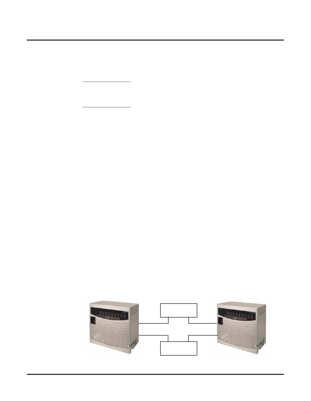
The Aspire Networking package provides a seamless connection of multiple systems into a single
“virtual” communications system using ISDN (PRI/BRI) and VoIP lines with a uniÞed numbering
plan. The ISDN Networking is only available with the Aspire M/L//XL - Aspire S must use IP
Networking. Aspire Networking will allow many companies to connect their telephone systems so
they appear as one. This will give them the ability to have only one operator to manage the system
and share one voice mail within the network. An extension user in the network can easily dial
another extension or transfer a call within the Aspire Networking System. Calls are passed from
network node to network node using a protocol that contains information about the source of the
call, the type of call and the destination of the call.
Introduction
About Aspire Networking
Introduction
◆
● Centralized Voice Mail
Centralized Voice Mail allows multiple networked systems to share a single voice mail system. This centralized voice mail can receive calls from and transfer calls to any destination in
any network node. Unanswered calls recall and route as if they were part of a single, much
larger system.
● Centralized Operator
Centralized Operator allows multiple networked systems to share a single operator. The operator can be accessed by a single digit code - if the operator is busy your call will automatically
queue until the operator becomes free. The operator can have a DSS console to show the status of users anywhere in the network.
This centralized operator can receive calls from and transfer calls to any destination in any network node. Unanswered calls recall and route as if they were part of a single, much larger system.
● Flexible Network Routing
Use network routes to set up “single channel” networking between many separate systems - or
use multiple networking channels per system for greater network performance. Data tables in
the system program deÞne the routing for each extension in each network node. These tables
are easily customized to meet the requirements of each networking conÞguration.
Users may place an intercom call or transfer a call to any extension at any location by simply
dialing an extension number. The system analyses each extension number received and determines how to route the call to its Þnal destination. The feature that handles this route selection
is called Flexible Routing (F-Routing). Once an extension number is dialed, the system
checks the routing, accesses the assigned trunk group and places the call. Each extension is
assigned a route or routes that decides which trunk group to access and any modiÞed dialed
data if required.
Networking
1

Introduction
About Aspire Networking
● Busy Lamp Indication
The status of an extension will be shown at a Hotline key/DSS Console on another networked
system. This allows a Centralized Operator to have lamp indication of extensions in the network or an extension user to have a Hotline key for a co-worker on another system.
● Call Forwarding
You can forward your calls to an extension at another networked extension. If you visit
another site within your network but forgot to set a call forward. then use Follow Me to have
your calls forwarded to you. Follow Me is also useful if you have an Aspire Wireless handset.
If your handset is subscribed at the site you are visiting then you can use Follow Me to have
your calls forwarded to your Aspire Wireless handset.
● Conference
An extension can have a conference call that includes co-workers at another system within the
network.
● Direct Inward Dial (DID)
A DID call can be routed to any extension within the network. This allows an extension to
receive a DID call from any other system in the network. Along with trunk access, it is possible for an extension on a system that has no trunk lines to use the trunks of another system in
the network.
● ARS/Flexible Network Routing
Use network routes to set up “single channel” networking between many separate systems - or
use multiple networking channels per system for greater network performance. Data tables in
the system program deÞne the routing for each extension in each network node. These tables
are easily customized to meet the requirements of each networking conÞguration.
Users may place an intercom call or transfer a call to any extension at any location by simply
dialing an extension number. The system analyzes each extension number received and determines how to route the call to its Þnal destination. There are two types of programming which
can handle this route selection - ARS and Flexible Routing (F-Routing). Up to 48 routes are
available for networking. Once an extension number is dialed, the system checks the routing,
accesses the assigned trunk group and places the call. Each extension is assigned a route or
routes that decides which trunk group to access and any modiÞed dialed data if required.
● Paging
Networking allows a user to place a Paging call to a networked system. If you need to get
through to a co-worker who is not at their desk, a page can be made to their system.
● Trunk Access
An extension can access a trunk line at another system in the network. The user dials the standard trunk access code and the system will automatically route the call to the system that has
trunks connected.
2 ◆ Networking

Aspire Requirements
There are two methods available for Networking connections as shown in following table.
Interface Description Comments
Introduction
About Aspire Networking
ISDN
(PRI ISDN
available with
Aspire M/L/
XL Only)
VoIP Using H.323 protocol for voice
Using Q.931-based proprietary
protocol, Basic Rate Interface
and Primary Rate Interfaces are
available.
transmit protocol.
• A PRIU or BRIU PCB is required for each
network connection.
• A minimum version of Þrmware is required
for the ISDN PCB.
BRIU PCB - Firmware 2.6
PRIU PCB - Firmware 2.0
• Using ISDN Networking the system provides
up to 256 B-channel ports which can be used
for Networking.
• A PRIU circuit will take 24 ports and each
BRI circuit will take 2 ports.
• These ISDN Networking ports are independent of the trunk and station ports available
on the system.
• A VOIPU PCB is required, as well as an
ethernet connection to the NTCPU.
• No speciÞc Þrmware version required.
• Using IP Networking the maximum quantity
of simultaneous calls is limited by the availability of resources on the VOIPU PCB’s
installed. A maximum of sixteen 16VOIPU
PCB’s can be installed each with a 16 port
expansion daughter card giving a maximum
of 512 speech channels (this number depends
on the system and the NTCPU type).
• The maximum quantity of calls may also be
reduced by the compression mode (CODEC
type) of the VOIPU PCBs, this is selectable
by the installer in Program 84-12-28. Refer
to the Aspire IP Manual for further detail.
Aspire S Requirements
● IP Networking is supported by the Aspire S KSU.
● An ENTU LAN Connection PCB is required with the VOIPU PCB. The system will not start
up if the ENTU is not installed.
● A VOIPU PCB with an ethernet connection to the ENTU PCB is required for connection.
Aspire NTCPU Requirements
● Networking is not supported on the 64-port Basic NTCPU (P/N 0891002).
● A Feature Upgrade PAL chip (P/N 0891039) is required for the Basic NTCPU or an Enhanced
NTCPU (P/N 0891038) can be used to enable Networking.
● A PRIU (Þrmware 2.0 or higher), BRIU (Þrmware 2.6 or higher), or VOIPU PCB with an eth-
ernet connection to the NTCPU is required for connection.
Networking ◆ 3
Introduction
About Aspire Networking
Networking Software Levels
It is advisable to have compatible levels of Aspire software installed on all systems within the Network. Although the basic Networking operation will operate correctly, there could be problems
with features that are only available from a given level of software.
Aspire Software V2.01
● Two Aspire systems can be installed in the network.
● Networked Park Hold should not be used.
Aspire Software V2.5x
● More than two Aspire systems can be installed in the network.
The networked systems can use a combination of PRI, BRI or VoIP PCBs. Refer to
Networking Using Mixed PCBs (PRI, BRI or VoIP) (page 4).
● For Networks with more than 10 systems.
● Networked Park Hold should not be used.
How Many Aspires can be Installed in a Single Network?
The Aspire system software version 2.5x allows you to install up to 10 Aspires within the network.
With software prior to version 2.5x, you should not install more than two systems in a network.
All systems must have either the 64-port NTCPU with Feature Upgrade PAL (P/N 0891002 and
0891039) or the Enhanced NTCPU (P/N 0891038) installed and version 2.5x software or later is
recommended.
Refer to Multi-Site Networking in this manual for information on installing more than two Aspire
systems in a network.
Networking Using Mixed PCBs (PRI, BRI or VoIP)
A network can consist of a combination of VOIPU, PRI and BRI PCBs. In order to create a network
using mixed media, you must keep a direct connection between the systems. IP resources will
receive priority over ISDN resources in a mixed media network. Refer to the following mixed
media examples:
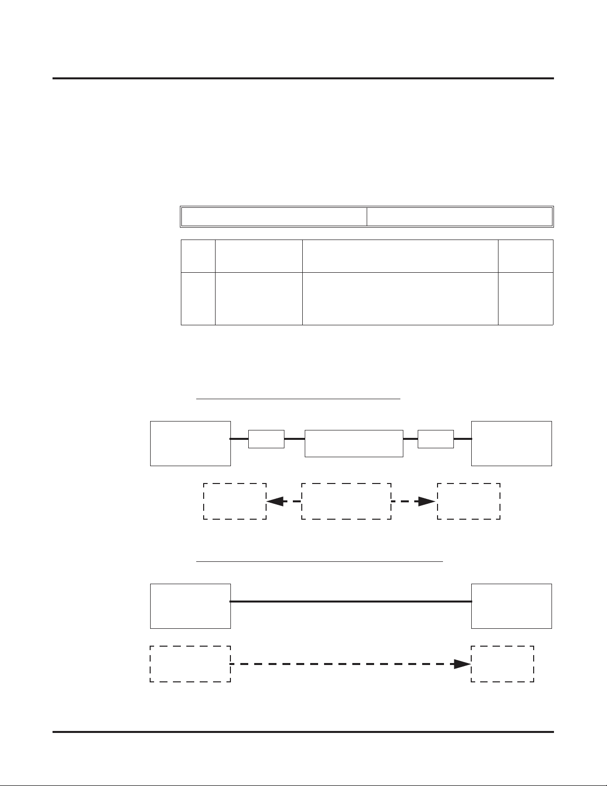
Networking via IP and ISDN (as a backup for extra resources)
This connection will work because each system is connected via the VOIPU and PRI/
BRI PCBs. The IP resources will get priority. The PRI resources will be selected when the
IP resources are in use or unavailable.
Hub
VOIPU
VOIPU
PRI PRI
CSU
Aspire A
4 ◆ Networking
Aspire B

Multi-Site Networking via IP and ISDN
This connection will NOT work because System C cannot access System A.
Introduction
About Aspire Networking
Hub
VOIPU
Aspire A
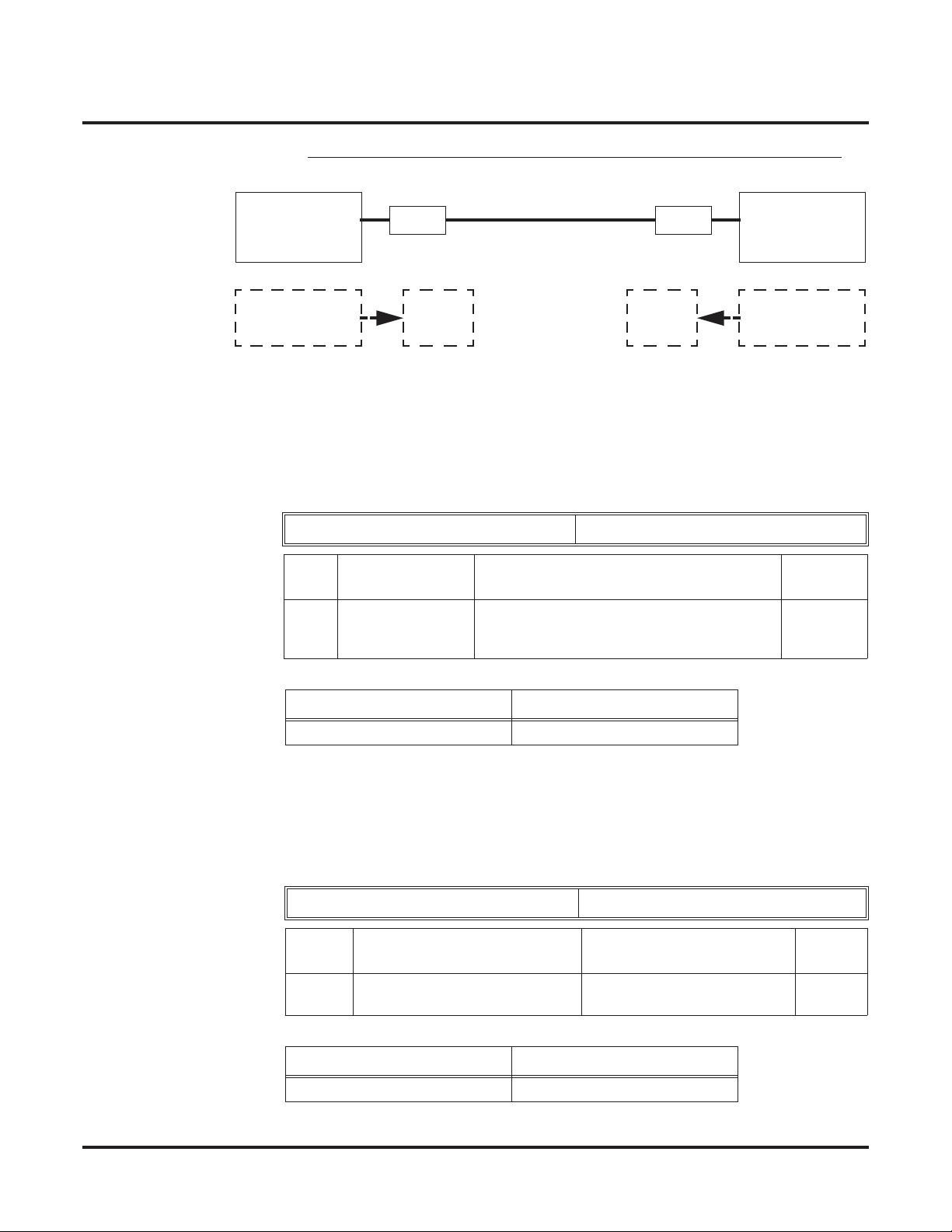
Multi-Site Networking via IP and ISDN
This connection will work as all systems are inter-connected. The IP resources will get
priority when System A accesses System B. When System A access System C, a PRI
resource will be used. In this setup, System A and System B must each have 1 VOIPU and
2 PRIU PCBs. System C must have 2 PRIU PCBs.
Aspire C
Hub
VOIPU
Aspire B
PRI/BRI
PRI/BRI
CSU
VOIPU
PRI PRI
CSU
Aspire A
PRI
CSU
Networking ◆ 5
PRI
Aspire C
VOIPU
Aspire B
PRI
PRI
CSU

Introduction
Available Features
Available Features
Available Features
911 Call Routing : Using ARS Class of Service Matching to Call Local
Authorities (page 39)
ARS/F-Route (page 40)
Barge In (page 47)
BLF Indication (at Hotline / DSS Console key) - refer to Hotline / Direct
Station Selection (DSS) (page 72)
Call Forwarding / Do Not Disturb Override (page 50)
Caller ID Display (page 56)
Call Forwarding (page 48):
Immediately
Busy
No Answer
Both Ring
Call Forwarding with Follow Me (page 52)
Call Forward, Off-Premise (page 51)
Call Waiting / Camp On (page 53)
Callback (page 54)
Central OfÞce Calls, Placing: Seizing a trunk in a networked system
(page 57)
Channel Release Link (page 59)
Conference (page 60)
Department Calling (page 62)
Department Step Call (page 64)
Direct Inward Dialing (DID) (page 65)
Direct Inward Line (DIL) (page 66)
Direct Inward System Access (DISA) (page 67)
Fax Over Networking (page 69)
Hold (page 71)
Hotline / Direct Station Selection (DSS) (page 72)
Intercom (page 74): Change Voice/Signal Ring
Keep Alive Operation (page 75)
Last Number Redial (page 76)
Message Waiting (page 77)
Operator, Centralized (page 78)
Paging (page 79)
Park (page 81)
Ringdown Extension, Internal/External (page 83)
Feature Name
6 ◆ Networking

Selectable Display Messaging (page 84)
Toll Restriction (page 85)
Transfer (page 86)
Voice Mail, Centralized (page 89)
Voice Mail, Local (page 93)
Introduction
Available Features
Networking ◆ 7

Introduction
About This Manual
About This Manual
Using This Manual
This manual is in three sections:
● Section 1: Setting Up the Networking Feature
This section guides you step by step in setting up a basic Networking system. You'll learn how
to:
● Program the Aspire system for Networking
● Program the Aspire system for Networking with Voice Mail
● Set Up the Voice Mail for Networking
● Section 2: Features
This section provides details on system features and how they work with a networked system.
● Section 3: Programming Basics
This section describes the programming basics for the Aspire phone system.
Telephone Programming Instructions shows you how to enter the program’s data into sys-
tem memory. For example:
1. Enter the programming mode.
2. 15-07-01
15-07-01 TEL301
KY01 = *01
←←←← →→
→→
tells you to enter the programming mode, dial 150701 from the telephone dial pad. After you
do, you’ll see the message “15-07-01 TEL301” on the Þrst line of the telephone display. This
indicates the program number (15-07), item number (01), and that the options are being set for
extension 301. The second row of the display “KY01 = *01” indicates that Key 01 is being
programmed with the entry of *01. The third row allows you to move the cursor to the left or
right, depending on which arrow is pressed. To learn how to enter the programming mode, see
How to Enter the Programming Mode (page 102).
● Appendix: Examples of Aspire Networking ConÞgurations
This section shows diagrams and simple programming instructions for Aspire Networking.
8 ◆ Networking

Unique Considerations
◆ Read These Notes ◆
Simplifying Keyset Operation with One-Touch Keys...
A system phone user can access many features through Service Codes (e.g., Service Code *0
answers a Message Waiting from a co-worker). To streamline the operation of their phone, a keyset
user can store these codes under One-Touch Keys. This provides one-button operation for almost
any feature. To Þnd out more, read the One-Touch Calling feature in your Software Manual.
Programmable Keys...
When reading an instruction using programmable keys, you will see a notation similar to (PGM 1507 or SC 851: 06). This means that the key requires function code 06, and you can program this
code through Program 15-07 or by dialing Service Code 851. Refer to the Programmable Function
Keys feature in your Software Manual if you need more information.
Using Handsfree...
The manual assumes each extension has Automatic Handsfree. This lets a user just press a line key
or CALL key to answer or place a call. For extensions without Automatic Handsfree, the user must:
Lift the handset or press SPK for Intercom dial tone.
Lift the handset or press SPK, then press a line key for trunk dial tone.
Introduction
About This Manual
Networking ◆ 9

Introduction
About This Manual
- For Your Notes -
10 ◆ Networking

Setting Up The Networking Feature
Required System Programming
Setting Up The Networking Feature
Required System Programming
Section 1
Setting Up
The Networking Feature
Basic System Programming
The selection of an ISDN PRI, BRI, or VoIP PCB determines the type of programming you must do
on the Aspire. Refer to the ISDN Networking, VoIP Networking, or Multi-Site Networking section
which follows. You can also refer to the examples in the Appendix (page 237).
In addition to the programs detailed in this manual for the Networking feature, be sure to refer to
the Aspire Software Manual (P/N 0893200) for complete details on programming the ISDN or VoIP
features, as well as any other user features.
Networking ◆ 11

Setting Up The Networking Feature
ISDN Networking
ISDN Networking
ISDN Networking
Refer to Appendix (page 237) for an example of setting up a network using ISDN or
IP connections.
ISDN Networking is only available for the Aspire M/L/XL system. In addition, the
NTCPU must have a Feature Upgrade or Enhanced PAL chip installed.
Using Q.931-based proprietary protocol, Basic Rate Interface and Primary Rate Interfaces are
available for networking Aspire systems. PRI ISDN available with Aspire M/L/XL only. Using
ISDN Networking, the system provides up to 256 B-channel ports which can be used for Networking. One PRIU or BRIU PCB is required for connection to each networked system. A minimum
version of Þrmware is required for the ISDN PCB.
BRIU PCB - Firmware 2.6
PRIU PCB - Firmware 2.0
A PRIU circuit will take 24 ports and each BRI circuit will take 2 ports. These ISDN Networking
ports are independent of the trunk and station ports available on the system.
Telco Requirements
BRI
● Peer-to-Peer
● U-Point to Telco
● NI1/NI2 (National Standard 1 and 2) Compliant
● The system provides compatibility with ISDN Basic Rate (BRI) services, including:
· Basic BRI Call Control (BCC)
· Point-to-Point BRI Terminal Connection (no daisy-chaining)
· Point-to-Multipoint BRI Terminal Connection (daisy-chaining)
· Capacity of 96 BRI circuits and 192 BRI channels
PRI
● ESF/B8ZS
● DID (routes on the last 8 digits)
● Yield to Glare Customer Side
● Outbound Caller ID Number
● Inbound Caller ID Name and Number (as provided by the telco)
● NI1/NI2 (National Standard 1 and 2) Compliant
● FAS (Facility Associated Signaling) - D-channel resides on PRI
PRI Networking With Two Local Voice Mails, Masters Must Have Different
Numbering
When programming a PRI network with each system having their own local voice mail, the master
numbers for the voice mails must be deÞned in different series in Program 11-01. The second digit
of the extension number can not be the same. For example, 700 and 701 will not work, however 700
and 710 can be used.
Ring Groups
Ring groups are NOT shared between networked systems. The only way you can ring a phone in
Site A and Site B at the same time is to DIL a trunk to an extension or a virtual extension at Site B
and program Call Forward Both Ring to an extension or virtual extension at Site A.
12 ◆ Networking
Programming
Also refer to the Numbering Plan (page 32) feature for additional
required programming.
➻
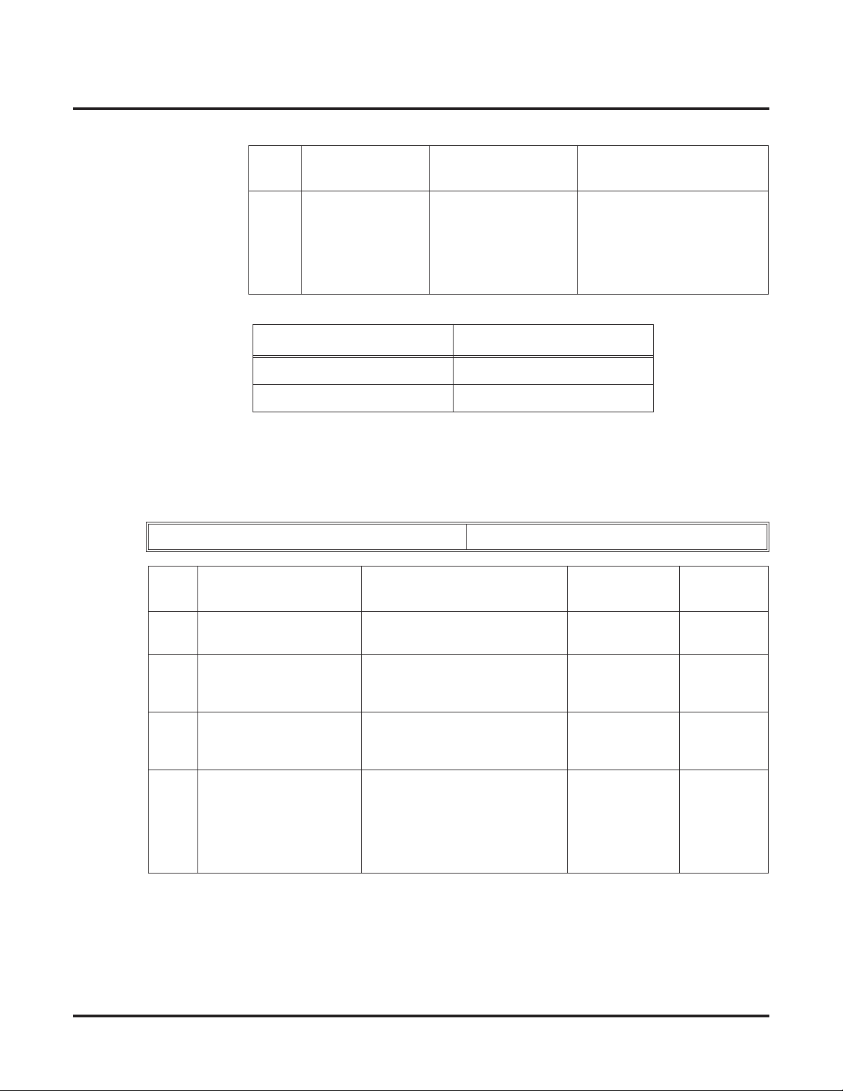
10-03-01 : PCB Setup - ISDN Line Mode
Determine the line mode of the ISDN. If Basic Rate Interface (BRI) is chosen, the setting
must be done for each line. The settings must match in all networked systems. The following
entries are acceptable for Networking.
Setting Up The Networking Feature
ISDN Networking
ISDN Line Number 01-08
Item
No.
01 ISDN Line Mode 3 = Network Mode (Leased Line)
A PRIU PCB will provide up to 24 channels - the BRIU PCB will provide 2 channels. Pro-
gram 10-32-01 can limit the quantity of channels available for PRIU interfaces.
The installation of each mode is shown in the following diagrams.
Mode 3 BRI/PRI Netw
Aspire
Mode 3
Master Side
Item Input Data Default
4 = Network Mode (Interconnected Line)
5 = Interconnection (Interconnected Line,
Fixed Layer 1 Forced NT Mode)
ork Mode (Lease Line)
NT1 NT1
T<-S
Slave Slave
BRI Leased Line
S->T
Clock Signal
Generator
Aspire
Mode 3
Slave Side
1
Mode 4 BRI/PRI Network Mode (Interconnected Line)
Aspire
Mode 4
Master Side
Clock Signal
Generator
Networking ◆ 13
S->T
Aspire
Mode 4
Slave Side
Slave
Setting Up The Networking Feature
ISDN Networking
Mode 5 BRI/PRI Interconnection Mode (Interconnected Line, Layer 1=NT)
Aspire
Mode 5
Slave Side
Clock Signal
Generator
GW GW
S<-T
Slave Slave
Ethernet
T->S
Aspire
Mode 5
Master Side
Clock Signal
Generator
➻ 10-03-03: PCB Setup - Connection Type
The connection type should be changed if Basic Rate Interface (BRI) is used. Only Point-to-
Point connection (1) is available for system interconnection.
ISDN Line Number 01-08
Item
No.
03 Connection Type 0 = Point-to-Multipoint (not available for
Item Input Data Default
Networking)
1 = Point-to-Point
0
Example:
System – A System – B
1: Point-to-Point 1: Point-to-Point
➻ 10-03-10 : PCB Setup - Master/Slave System
Determine which system will be the master system and which one(s) will be the slave sys-
tem(s). If one system is set as the Master, all the other systems must be set as the Slave. The
choice of Master/Slave is determined by the ISDN clock available at the Aspire. With a direct
connection: Master = S-Point, Slave = T-Point. With a telco connection: Master = T-Point,
Slave = T-Point. See the Appendix (page 237) for further detail.
ISDN Line Number 01-08
Item
No.
10 Master/Slave System
(Network Mode Only)
Example:
System – A System – B
1: Master 2: Slave
Item Input Data Default
0- Slave System
1- Master System
0
14 ◆ Networking

Setting Up The Networking Feature
ISDN Networking
➻ 10-03-11 : PCB Setup - Networking System Number
The Networking ID is used to select the access route for dialed digits. You can choose any
number 0 to 50 (0 equals no operation). This ID is used when setting the numbering plan for
the networked systems. The same ID number must be set in both 10-03-11 and 11-01. Refer to
Numbering Plan (page 32) for more on the numbering plan settings.
ISDN Line Number 01-08
Item
No.
10 Networking System Number
(Network Mode Only)
Example:
System – A System – B
Networking ID: 1 Networking ID: 1
Item Input Data Default
0-50 0
➻ 10-32-01 : PRI Networking Channel Limitation
With software 2.09 or higher, this program can be used to assign the number of B-channels to
be used for each ISDN PCB. This allows for fractional PRIs when used with multiple site net-
working. If this program is limited to less than "23" on one side of the network, then it also
limits both inbound and outbound network calls. This also applies on the other side of the net-
work as well.
(Default: Slots 1-16 = 23, Entries: 1-23)
➻ 11-02-01 : Extension Numbering
Assign the extension numbers to the ports. The extension number can be up to eight digits
long. The Þrst/second digit(s) of the number should be assigned in Program 11-01. This lets
an employee move to a new location (port) and retain the same extension number.
Networking ◆ 15

Setting Up The Networking Feature
IP Networking
IP Networking
Voice Over IP Networking
CAUTION
As with any Voice Over IP (VoIP) implementation, there are several issues that should be
considered when setting up IP Networking on the Aspire.
These issues are discussed in detail in the Aspire Voice Over IP Manual. Please refer to
this before installing IP Networking.
Refer to Appendix (page 237) for an example of setting up a network using ISDN or
IP connections.
Using H.323 protocol for voice transmit protocol, it is possible to network Aspire systems. VoIP
can be used to network the Aspire S, M, L, and XL systems.
● Using IP Networking the maximum quantity of simultaneous calls is limited by the availabil-
ity of resources on the VOIPU PCB’s installed. A maximum of sixteen 16VOIPU PCB’s can
be installed each with a 16 port expansion daughter card giving a maximum of 512 speech
channels (this number depends on the system and the NTCPU type).
● The maximum quantity of calls may also be reduced by the compression mode (CODEC type)
of the VOIPU PCB’s, this is selectable by the installer in Program 84-12-28. Refer to the
Aspire Software Manual (P/N 0893200) for further details.
When using IP Networking, keep the following items in mind:
● In order to keep the audio quality, prevent sending and receiving unnecessary packets by:
● not using a repeater hub with the Aspire system.
● turning off the Spanning Tree feature, if possible.
● Disable the SIP NAPT router in Program 10-12-06 (set to 0) to prevent the IP address from
being changed by any other equipment.
● Use equipment which provides an Auto-Negotiation feature, if possible.
● The UPnP feature is not guaranteed to work with the Aspire system.
● In order to use the Networking feature, the Aspire M/L/XL NTCPU must have a Feature
Upgrade or Enhanced PAL chip installed. The Aspire S requires the ENTU LAN card in order
to use VoIP PCBs.
● IP addresses are required for each site’s NTCPU, VoIP cards in each site, and the default gate-
way (inside IP address) from each site’s routers.
Ring Groups
Ring groups are NOT shared between networked systems. The only way you can ring a phone in
Site B and Site A at the same time is to DIL a trunk to an extension or a virtual extension at Site B
and program Call Forward Both Ring to an extension or virtual extension at Site A.
16 ◆ Networking

Setting Up The Networking Feature
IP Networking
In-Band/Out-of-Band DTMF Signaling
In-band signaling is the way to send DTMF tone just as audio (in band of the RTP packet). There is
no other message sent to the far end for the DTMF digits. Therefore, if this is used with G.729 protocol, the DTMF tone will not be received properly. At the level G.729 compresses the audio, it
affects the actual DTMF tone and it can not be interpreted by the far end. This is by the design of
VoIP and there is no way to correct it.
Out-of-band signaling sends a special message to the far end for the DTMF digits (out of band of
the RTP packet). The actual DTMF audio will be muted. There are two signaling types - RFC2833
and H.245. Both signaling types should work on every protocol (G.729, G.711, etc.).
Aspire software version 2.63 and higher supports out-of-band signaling, allowing DTMF digits to
be sent when using G.729 protocol. However, in-band signaling on G.729 will never work on any
phone system unless the deÞned compression rate is changed.
To enable the out-of-band signal function, you must have software 2.63 or higher, change Program
84-12-31 : H.323 Phone CODEC Information Setup - DTMF Relay Mode to RFC2833 (an
entry of "1"), and change 84-06-10 : VOIPU Setup - DTMF Behavior for the card slot of the VoIP
card to out of band (an entry of "2"). If these options are not set, DTMF tones will not be sent
across the network. This will affect voice mail as well as any other device requiring DTMF.
Call Transfer to i-Series System Via VoIP Connection
When an Aspire system is connected via a VoIP connection to an i-Series system in a tie-line type
setup, in order to transfer calls from the Aspire system to the i-Series, in addition to the VoIP programming, set up the Flexible Routing Tables as follows:
● Program 44-05-01 : ARS/F-Route Table ; Table Number 1 = 9 (Trunk Group for Aspire
VoIP Trunk)
● Program 10-23-02 : H.323 System Interconnection, IP Address ; System Number 3 =
172.16.9.10 (IP Address for i-Series System)
● Program 10-23-04 : H.323 System Interconnection, Alias Address ; System Number 3
= 4 (For Dial 4 Calls)
With this programming, the Aspire system will wait for the Trunk Interdigit Timer to expire before
dialing out after an i-Series extension (4xxx) is dialed.
If the F-Routing is set up with Program 44-05-01; Table Number 1 set to 103 (Networking) and
Program 10-27-01; System ID 3 = 172.16.9.10 (IP Address for i-Series), though the
i-Series system will be able to transfer calls to the Aspire, the Aspire system will not be able to
transfer to the i -Series.
Explanation of Routing for IP Networking
When a user places a call to a remote extension number the dialled digits are checked against the
Numbering Scheme in Program 11-01. This will provide the Node ID number of the route to the
remote system.
The Aspire will then Þnd the destination IP Address by searching Program 10-27 for the destination
IP Address for the given Node ID number.
Networking ◆ 17

Setting Up The Networking Feature
IP Networking
Quantity of Voice Paths Available
The quantity of voice calls that can be made at any one time are dependent on various factors.
● VOIPU Resource - A free VOIPU resource must be available at each Aspire system.
● Program 10-19 : The mode of each VOIPU resource can be conÞgured, modes 0 (ICM/Trunk)
or 3 (NTW) can be used by Aspire Networking calls.
● IP Network Bandwidth Restrictions - These limitations are beyond the scope of the Aspire. If
there is not enough bandwidth available the call can not be maintained.
VOIPU PCB IP Address Options
A static IP address can be assigned to the VOIPU PCB. The IP address can also be assigned by
DHCP by setting Program 84-04-01.
18 ◆ Networking

Setting Up The Networking Feature
Programming
Also refer to the Numbering Plan (page 32) feature for additional
required programming.
➻
10-12-01 : NTCPU Network Setup - IP Address
Select the IP address of the NTCPU (default: 172.16.0.10). A static IP address is required by
the NTCPU. Each Aspire system in the network must have a unique IP address. The system
must be reset in order for the change to take effect.
➻ 10-12-02 : NTCPU Network Setup - Subnet Mask
Select the Subnet Mask to be used by the IP server (default: 255.255.0.0).
IP Networking
Item
No.
01 NTCPU
02 NTCPU
Item Input Data Default Conditions
IP Address
Subnet
Mask
1.0.0.1 - 126.255.255.254
128.1.0.1 -191.254.255.254
192.0.1.1 - 223.255.254.254
128.0.0.0
240.0.0.0
254.0.0.0
255.192.0.0
255.252.0.0
255.255.128.0
255.255.248.0
255.255.255.0
255.255.255.224
255.255.255.252
Example:
192.0.0.0
248.0.0.0
255.0.0.0
255.224.0.0
255.254.0.0
255.255.192.0
255.255.252.0
255.255.255.128
255.255.255.240
255.255.255.254
System – A System – B
IP Address: 172.16.0.10 IP Address: 172.16.0.11
224.0.0.0
252.0.0.0
255.128.0.0
255.248.0.0
255.255.0.0
255.255.224.0
255.255.254.0
255.255.255.192
255.255.255.248
255.255.255.255
172.16.0.10
255.255.0.0 The setting of SubnetMask is mistaken when
all Host Address are 0.
If the network section
is:
0,
127
128.0
191.255
192.0.0
223.255.255
The setting of SubnetMask is mistaken.
Subnet Mask: 255.255.0.0 Subnet Mask: 255.255.0.0
➻ 10-20-01 : LAN Setup for External Equipment - TCP Port
DeÞne the TCP port number for communicating to external equipment. The port number
deÞned should be the same in each networked system.
Type of external equipment 1- CTI Server
2- ACD MIS
3- - Reserve 4- Network Listener
5- SMDR
6- DIM Access
Networking ◆ 19
Setting Up The Networking Feature
IP Networking
Item
No.
01 TCP Port / Network
Listener
Example:
External Equipment: 4 External Equipment: 4
Item Input Data Default
0-65535 External Device 1 = 0
External Device 2 = 0
External Device 3 = 0
External Device 4 = 30000
External Device 5 = 0
External Device 6 = 0
System – A System – B
Port: 30000 Port: 30000
➻ 10-23-xx : H.323 System Interconnection
deÞne the IP address of another system, call control port number and alias address for Aspire system inter-connection. This program is activated when Program 10-17-01 and 10-18 are registered.
Depending on your system software, the system allows for up to 50 or 1000 systems to be registered.
System Number 0001-1000
Item
No.
01 System Interconnection 0 = No
02 IP address 1.0.0.1_126.255.255.254
03 Call Control Port 1-65535 1720 Activated
04 Alias Address
If Program 10-28-04 is
used, its entry must be
numeric as 10-23-04 does
not permit text entry - only
numeric entries.
Item Input Data Default
0
1 = Yes
0.0.0.0 Activated
128.1.0.1 _191.254.255.254
192.0.1.1 _223.255.254.254
Max 12 addresses No Setting Activated
Related
Program
when
10-23-01=1
when
10-23-01=1
when
10-23-01=1
10-28-04
20 ◆ Networking

Setting Up The Networking Feature
IP Networking
➻ 10-27 : IP System ID - IP Address
Set the System ID, IP address, and Call Procedure Port of the networked IP systems.
If setting up a multi-site network, you may wish to deÞne each system the same in this program. This will help reduce the confusion if the same ID is programmed in each system. (You
do not need to program the IP address for the system being programmed.) Using the following
sample programming, Network 1 is ID 1, Network 2 is ID 2, Network 3 is ID 3.
Program 10-27-01 Entries
Network 1 Network 2 Network 3
System ID 1
System ID 2
System ID 3
Item
No.
01 IP Address
System ID is related
with the System ID in
the Numbering Plan
(Program 11-01-01).
When the digits are
analyzed and the system ID is determined
from the system data
set in the Numbering
Plan, the Networking
call will be sent to the
IP Address set in this
program.
172.16.0.10
172.16.0.11
172.16.0.12
System ID 01-50
Item Input Data Default
1.0.0.1_126.255.255.254
128.1.0.1 _191.254.255.254
192.0.1.1 _223.255.254.254
172.16.0.10
172.16.0.11
172.16.0.12
0.0.0.0 11-01-01
172.16.0.10
172.16.0.11
172.16.0.12
Related
Program
10-12-01
The IP Address should
be the IP Address of
the peer NTCPU (Program 10-12-01).
02 Call Procedure Port
The Port Number
should be set with the
same value as the
H.225 setup port in
Program 84-02-33.
Networking ◆ 21
1-65535 1730 84-02-33

Setting Up The Networking Feature
IP Networking
Example:
System – A System – B
System ID: 1 System ID: 1
IP Address: 172.16.0.11
(from Program 10-12-01)
Port: 1730 Port: 1730
➻ 11-02-01 : Extension Numbering
Assign the extension numbers to the ports. The extension number can be up to eight digits
long. The Þrst/second digit(s) of the number should be assigned in Program 11-01. This lets
an employee move to a new location (port) and retain the same extension number.
➻ 84-01-xx : CODEC Information Basic Setup
DeÞne the data of H.323 trunks. These settings apply to H.323 Trunks only. Refer to Program
84-12-xx for H.323 extensions and IP networking.
Note that the value of Item 33 (Audio Capability Priority) determines which CODEC settings
to use. This means, for example, that if G.711 is selected in Item 33, the settings in Items 5-12
and 19-21 will be ignored.
Item
No.
01 -- Not Used --
02 Number of G711 Audio Frame 2 = 20 ms
Item Input Data Default Description
3 = 30 ms
IP Address: 172.16.0.10
(from Program 10-12-01)
3 Maximum number of G711 Audio
Frame
03 G711 Silence Detection Mode 0:Disable
1:Enable
04 G711 type 0:A-law
1: u-law
05 G729 Audio Frame 1 = 10 ms
2 = 20 ms
3 = 30 ms
4 = 40 ms
5 = 50 ms
6 = 60 ms
7 = 70 ms
8 = 80 ms
06 G729 0:Disable
1:Enable
07 G.729 Jitter Buffer Minimum 0-500 ms 30
08 G.729 Jitter Buffer Type 0-500 ms 60
09 G.729 Jitter Buffer Maximum 0-500 ms 120
10 -- Not Used --
0DeÞne whether the silence detection
1 Set the type of G711
3 Maximum number of G729 Audio
0
enables on G711 or not
(A-law or u-law)
Frame
22 ◆ Networking

Setting Up The Networking Feature
IP Networking
Item
No.
11 Number of G723 Audio Frame 1 = 30 msec
12 G723 0:Disable
13 Maximum value of Jitter Delay 0-65535 msec 60 msec Maximum value of Jitter Delay for
14 -- Not Used --
15 Jitter Buffer Mode 1 = static
16 G.711 Jitter Buffer (min.) 0~145 ms 30 Set the minimum value of G.711 Jitter
17 G.711 Jitter Buffer (typ) 0~145 ms 60 Set the average value of G.711 Jitter
18 G.711 Jitter Buffer (max) 0~145 ms 120 Set the maximum value of G.711 Jitter
Item Input Data Default Description
1 Maximum number of G723 Audio
2 = 60 msec
0
1:Enable
1 Set the mode of Jitter Buffer
2 = adaptive during
silence
3 = adaptive immedi-
ately
Frame
audio delay
Buffer
Buffer
Buffer
19 G.723,G.729 Jitter Buffer (min.) 0~500 ms 30 Set the minimum value of G.723,
G.729
Jitter Buffer
20 G.723, G.729 Jitter Buffer (typ) 0~500 ms 60 Set the average value of G.723, G.729
Jitter Buffer
21 G.723,G.729 Jitter Buffer (max) 0~500 ms 120 Set the maximum value of G.723,
G.729
Jitter Buffer
22 VAD threshold 0-30
(-20db~+10db)
0:-20db (-50dbm)
1:-19db (-49dbm)
:
20 = 0db
(-30dbm)
:
29 = 9dbm
(-21dbm)
30:10dbm
(-20dbm)
20 Threshold of silence detection
Change value based –30
Become invalid item if item 03 is set
to Disable
Networking ◆ 23

Setting Up The Networking Feature
IP Networking
Item
No.
23 Idle Noise Level 5000-7000
24 Echo canceler mode 0 = Disable
25 Echo canceler tail size 1 = 8 ms
26 Echo canceler nlp mode 0 = Disable
27 Echo canceler nlp noise 40-70 (-40~-70)
28 Echo canceler cng cfg 0 = adaptive
Item Input Data Default Description
(-5000 ~ -7000dbm)
5000 = -5000dbm
:
7000 = -7000dbm
1 = Enable
2 = 16 ms
3 = 32mS
1 = Enable
40 = -40 dbm
:
70 = -70 dbm
1 = Þxed
7000 Noise level of silence
1 Determine whether or not to use Echo
canceller.
2 Become invalid item if item 24 is set
to Disable
0 Non-linear processing mode
70 Become invalid item if item 26 is set
to Disable
0 Become invalid item if item 26 is set
to Disable
29 Echo canceler 4w det 0 = Disable
1 = Enable
30 TX Gain 0-28 (-14~+14)
0 = -14 dbm
1 = -13 dbm
:
14 = 0 dbm
:
27 = 13 dbm
28 = 14 dbm
31 RX Gain 0-28 (-14~+14)
0 = -14 dbm
1 = -13 dbm
:
14 = 0 dbm
:
27 = 13 dbm
28 = 14 dbm
32 -- Not Used --
33 Audio Capability Priority 0:G711 PT
1:G723 PT
2:G729 PT
0
14
14
0 The option selected here determines
what other options are applied from
this program.
24 ◆ Networking

Setting Up The Networking Feature
IP Networking
Item
No.
34 Bandwidth Control 0:Disable
35 Maximum Bandwidth 0-65535kbps 0 The maximum total bandwidth limita-
36 Fax Max Rate 24 = V.27ter, 2400 bps
37 Fax Playout FIFO Nominal
Delay
38 Fax Packet Size 20-48 bytes 20
39 Fax Modem Transmit Level 0-13
40 Fax Modem CD Threshold 0 = -26dBm
Item Input Data Default Description
0 Controls the voice bandwidth on an
1:Enable
5
48 = V.27ter, 4800 bps
72 = V.29, 7200 bps
96 = V.29, 9600 bps
120 = V17, 12000 bps
144 = V.17, 14400 bps
0-600 ms 300 ms Increase the value for networks which
6
0dBm -13dBm
1 = -33dBm
2 = -43dBm
(-6dBm)
1
H.323 trunk.
tion for voice packets.
experience large packet losses.
41 Fax No Activity Timeout
Duration
42 Override Encapsulation Method 0 = Open Channel
43 High Speed Data Packet Rate 10-80 ms 60
44 Low Speed Data Redundancy 0-8 0
45 High Speed Data Redundancy 0-2 0
46 TCF Handling Method 1 = TCF is Locally Gen-
47 Maximum Low Speed Data
Packetization
48 Transmit Network Timeout 10-32000 sec 150 sec
49 Eßag Start Timer 0-65535 2600 ms
50 Eßag Stop Timer 0-65535 2300 ms
10-32000 sec 30
1 T.38/TRP UDP
DeÞned Packet Encap-
sulation
1 = T.38 UDP
2 = T.38/TRP UDP
1 For H.323 negotiation
erated and Checked
2 = TCF is Sent Over
the Network
1
Voice-Fax
Close-Reopen
51 Fax Relay: Scan Line Fix Up
Feature
Networking ◆ 25
0 = Disable
1 = Enable
1

Setting Up The Networking Feature
IP Networking
Item
No.
52 Fax Relay: Eßags for First DIS 0 = Disable
53 Fax Relay: FOP Protocol
Enhancement
54 Fax Relay: NSF Override 0 = Disable
55 T30: ECM 0 = Disable
56 T30: MR Page Compression 0 = Disable
57 NSF Country Code 0-65535 Blank Fax Relay - NSF Override Disable
58 NSF Vendor Code 65535 Blank Fax Relay - NSF Override Disable
59 Fax Relay Function 0 = Disable
60 Echo Canceller ConÞg Type 0 = Auto
Item Input Data Default Description
1
1 = Enable
0 = Disable
1 = Enable
1 = Enable
1 = Enable
1 = Enable
1 = Enable
1 = Type 1
2 = Type 2
3 = Type 3
1
0
1
1
0 Determine whether or not the Fax
Relay function should be used.
1
61 Echo Auto Gain Control 0 - 5 0
62 H.323 DTMF Payload Number 0 = VOIPU
1 = RFC2833
2 = H.245
3 = Disable
Conditions
You must log out of system programming in order for changes to the following items will take
affect:
Item 39 Item 53
Item 40 Item 54
Item 41 Item 55
Item 49 Item 56
Item 50 Item 57
Item 51 Item 58
Item 52
0DeÞne the H.323 DTMF Payload
Number.
26 ◆ Networking

Setting Up The Networking Feature
IP Networking
➻ 84-02-35 : H.225, H.245 Information Basic Setup - Fast Start Mode
If VoIP is used for networking, the Fast Start option must be enabled.
Item
No.
35 Fast Start 0: Disable
Item Input Data Default
1
1: Enable
➻ 84-05-01 : VOIPU IP Address Setup - IP Address
For each VOIPU PCB, enter the IP address for the VOIPU PCB (default: slot 1=172.16.0.20,
slot 2 = 172.16.0.21, etc). The IP address should be increased according to the number of
VOIPU PCBs. This entry becomes invalid if Program 84-04 is set to "1" (DHCP enabled).
Slot Number 01-16
Item Input Data Default Description Related Program
IP
Address
1.0.0.1–126.255.255.254
128.1.0.1–191.254255.254
192.0.1.1–223.255.254.254
Slot 1: 172.16.0.20
Slot 2: 172.16.0.21
Slot 3: 172.16.0.22
Slot 4: 172.16.0.23
Slot 5: 172.16.0.24
Slot 6: 172.16.0.25
Slot 7: 172.16.0.26
Slot 8: 172.16.0.27
Set IP Address of
VoIPU PCB.
IP Address will be
increased in accordance with number of
slot.
84-04
This becomes invalid data
if Program 84-04 is set to
1:Enable.
Example:
System – A System – B
IP Address: 172.16.0.20 IP Address: 172.16.0.21
Subnet Mask: 255.255.0.0 Subnet Mask: 255.255.0.0
➻ 84-06-10 : VOIPU Setup - DTMF Behavior
Set the DTMF option to “2” when using the networking feature. The system programming
must be exited before these program options to take affect.
Input Data
SLOT Number 01-16
10 DTMF Behavior 0 = DTMF Relay disabled
1 = In-Band DTMF relay,
do NOT report to Host
processor
2 = Out of Band DTMF
relay, do not pass tones as
voice
0 • Inbound - DTMF is transferred by
RTP packets.
• Outbound - DTMF is transferred by
H.245 protocol.
This setting allows DTMF digits to be
relayed between the VOIPU PCBs. It is
recommended that this is set to “1”.
Networking ◆ 27

Setting Up The Networking Feature
IP Networking
➻ 84-12-xx : H.323 Phone CODEC Information Basic Setup
Setup the CODEC information of H.323 phones and IP Networking. Refer to Program 84-12xx for H.323 extensions and IP networking.
Input Data
Item
No.
01 G711 Audio Frame
Prior to software 2.63, the only entry possible was “2”
or “3”. With software 2.63+, additional entries are
available.
Note: Currently, only the Aspire S system can use the
10ms setting. Aspire will provide this option in the
future.
02 G711 VAD Mode 0 = Disable
03 G711 Type 0 = A-law
04 G.711 Jitter Buffer Min 0~145 ms 30
05 G.711 Jitter Buffer Type 0~145 ms 60
06 G.711 Jitter Buffer Max 0~145 ms 120
07 G.729 Audio Frame
Prior to software 2.63, only entries 3-8 were available.
With software 2.63+, additional entries are available.
Item Input Data Default
1 - 3
(1 = 10ms,
2 = 20 ms,
3 = 30ms)
1 = Enable
1 = μ-law
1-8
(1 = 10ms,
2 = 20ms, etc.)
Related
Program
3
0
1
3
Note: Currently, only the Aspire S system can use the
10ms setting. Aspire will provide this option in the
future
08 G.729 VAD Mode 0 = Disable
1 = Enable
09 G.729 Jitter Buffer Min 0~500 ms 30
10 G.729 Jitter Buffer Type 0~500 ms 60
11 G.729 Jitter Buffer Max 0~500 ms 120
12 G.723 Audio Frame 1-2 1
13 G.723 VAD Mode 0 = Disable
1 = Enable
14 G.723 Jitter Buffer Min 0~500 ms 30
15 G.723 Jitter Buffer Type 0~500 ms 60
16 G.723 Jitter Buffer Max 0~500 ms 120
28 ◆ Networking
0
0

Setting Up The Networking Feature
IP Networking
Item
No.
17 Jitter Buffer Mode 1 = static
18 VAD Threshold 0-30 (19db~+10db,
19 Idle Noise Level 5000-7000
20 Echo Canceler Mode 0 = Disable
Item Input Data Default
2 = adaptive during
silence
3 = adaptive immed
Adaptec threshold)
0 = Adaptec threshold
1 = -19db(-49dbm)
:
20 = 0db (-30dbm)
:
29 = 9dbm(-21dbm)
30 = 10dbm(-20dbm)
(-5000_-7000dbm)
5000:-5000dbm
:
7000:-7000dbm
1 = Enable
Related
Program
1
20
7000
1
21 Echo Canceler Tail Size
84-12-20 - Disable
22 Echo Canceler NLP Mode
Non-linear processing mode
23 Echo Canceler NLP Noise
84-12-22 - Disable
24 Echo Canceler CNG CFG
84-12-22 - Disable
25 Echo Canceler 4w Det 0 = Disable
26 TX Gain 0-28 (-14~+14)
1 = 8 ms
2 = 16 ms
3 = 32mS
0 = Disable
1 = Enable
40-70 (-40~-70)
40 = -40 dbm
:
70 = -70 dbm
0 = adaptive
1 = Þxed
1 = Enable
0 = -14 dbm
1 = -13 dbm
:
14 = 0 dbm
:
27 = 13 dbm
28 = 14 dbm
2
0
70
0
0
14
Networking ◆ 29

Setting Up The Networking Feature
IP Networking
Item
No.
27 RX Gain 0-28 (-14~+14)
28 Audio Capability Priority 0:G711_PT
29 Echo Canceller ConÞg Type 0 = Auto
30 Echo Auto Gain Control 0 - 5 0
31 DTMF Relay Mode
In-band signaling is the way to send DTMF tone just
as audio (in band of the RTP packet). There is no other
message sent to the far end for the DTMF digits.
Therefore, if this is used with G.729 protocol, the
DTMF tone will not be received properly. At the level
G.729 compresses the audio, it affects the actual
DTMF tone and it can not be interpreted by the far
end. This is by the design of VoIP and there is no way
to correct it. If G.729 is used, then out-of-band signaling is required when DTMF digits need to be sent over
the network.
Item Input Data Default
0 = -14 dbm
1 = -13 dbm
:
14 = 0 dbm
:
27 = 13 dbm
28 = 14 dbm
1:G723_PT
2:G729_PT
1 = Type 1
2 = Type 2
3 = Type 3
0 = Disable
1 = RFC2833
2 = VOIPU
Related
Program
14
0
0
2 84-06-10 :
VOIPU Setup
- DTMF
Behavior for
the card slot of
the VoIP card
to out of band
(an entry of
"2")
Out-of-band signaling sends a special message to the
far end for the DTMF digits (out of band of the RTP
packet). The actual DTMF audio will be muted. There
are two signaling types - RFC2833 and H.245/VOIPU.
Both signaling types should work on every protocol
(G.729, G.711, etc.). RFC2833 must be selected in
order for DTMF digits to be sent over the network.
32 FAX Relay
Select "2" for FAX Relay to SLT (Program 15-0303:special), Trunk and networking.
Refer to Program 84-01-36 through 84-01-57 for FAX
Relay options.
30 ◆ Networking
0 = Disable
1 = Enable
2 = Each Port Mode
0

Multi-Site Networking
Setting Up The Networking Feature
Multi-Site Networking
Multi-Site Networking
Multi-Site Networking is a network of three or more Aspire systems connected by either ISDN or IP.
The conÞguration for three or more sites is the same as for two sites, refer to ISDN Networking
(page 12) or IP Networking (page 16) for details of setting up the Aspire systems. Please refer to
the following list before installing Multi-Site Networking.
● All systems must have NTCPU software version V2.5x or later.
● It is recommended that all systems in the network have compatible levels of software
installed. Refer to Networking Software Levels (page 4).
● A Feature Upgrade PAL chip (P/N 0891039) is required for the Basic NTCPU or an Enhanced
NTCPU (P/N 0891038) can be used to enable Networking.
● A network can combine both ISDN and IP Networking within the same network as long as
there is direct connection between each system. Refer to Networking Using Mixed PCBs
(PRI, BRI or VoIP) (page 4) for additional information.
● All systems within the network must have a direct connection to all other systems in the net-
work. This makes IP Networking the more practical type for Multi-Site Networks - only one
VOIPU PCB is required in a system cabinet regardless of the number of networked systems,
where PRI or BRI would require one PCB be installed in a system cabinet for each networked
system.
● VOIPU resources will be used at each system when a call is transferred. For example, a call
that originates from System A and calls System B, is held and transferred to System C, will
use VOIPU resources at all three systems.
The same also applies for ISDN Networking - an ISDN channel will be used from System A
to B and also from System B to C.
Networking ◆ 31

Setting Up The Networking Feature
Numbering Plan
Numbering Plan
Numbering Plan
11-01-01 : System Numbering
➻
Set the system’s internal (Intercom) numbering plan and system ID to route to networked systems. The numbering plan assigns the Þrst and second digits dialed and affects the digits an
extension user must dial to access other extensions and features, such as service codes and
trunk codes, within a networking node or to reach another node.
Consider using a "UniÞed Numbering Plan" for extensions. This gives every extension in the
network a unique extension number. The extension number can then be used to route a call to
the proper node. This also allows the same extension number to be dialed at any node to reach
a given extension.
CAUTION
Improperly programming this option can adversely affect system operation. Make
sure you thoroughly understand the default numbering plan before proceeding. If you
must change the standard numbering, use the chart for System Numbering
(page 133) to keep careful and accurate records of your changes.
Before changing your numbering plan, use the PC Program or Program 90-03 to
make a backup copy of your system’s data.
PRI Networking With Two Local Voice Mails, Masters Must Have Different
Numbering
When programming a PRI network with each system having their own local voice mail, the
master numbers for the voice mails must be deÞned in different series in Program 11-01. The
second digit of the extension number can not be the same. For example, 700 and 701 will not
work, however 700 and 710 can be used.
Changing the numbering plan consists of three steps:
1. Enter the digits you want to change.
2. Specify the length of the code you select to change.
3. Assign a function to the code selected.
Step 1: Enter the digit(s) you want to change
You can make either single or two digit entries. In the Dialed Number column in the System
Numbering (page 133) table, the nX rows (e.g., 1X) are for single digit codes. The remaining
rows (e.g., 11, 12, etc.) are for two digit codes.
● Entering a single digit affects all the Dialed Number entries beginning with that digit. For
example, entering 6 affects all number plan entries beginning with 6. The entries you make
in step 2 and step 3 below affect the entire range of numbers beginning with 6. (For example, if you enter 3 in step 2 the entries affected would be 600-699. If you enter 4 in step 2
below, the entries affected would be 6000-6999.)
32 ◆ Networking

Setting Up The Networking Feature
Numbering Plan
● Entering two digits lets you deÞne codes based on the Þrst two digits a user dials. For
example, entering 60 allows you to deÞne the function of all codes beginning with 60. In
the default program, only * and # use two-digit codes. All the other codes are single digit.
If you enter a two digit code between 0 and 9, be sure to make separate entries for all the
other two digit codes within the range as well. This is because in the default program all
the two digit codes between 0 and 9 are undeÞned.
Step 2: Specify the length of the code you want to change
After you specify a single or two digit code, you must tell the system how many digits comprise the code. This is the Number of Digits Required column in the System Numbering
(page 133) table. In the default program, all codes from 100-999 are three digits long. Codes
beginning with 0 are one digit long. Codes beginning with * are 3 digits long and codes beginning with # are 4 digits long.
Step 3: Assign a function to the code selected
After entering a code and specifying its length, you must assign its function. This is the Dial
Type column in the System Numbering (page 133) table. The choices are:
Dial Types Dial Type Description Related Program
0 - Not Used -
1 Service Code 11-10 : Service Code Setup (for System Administrator)
11-11 : Service Code Setup (for Registration)
11-12 : Service Code Setup (for Service Access)
11-13 : Service Code Setup (for ACD)
11-14 : Service Code Setup (for HOTEL)
11-15 : Service Code Setup (Special access)
2 Extension Number 11-02 : Extension Numbers
11-04 : Virtual Extension Numbers
11-06 : 2PGDAD (ACI) Extension Numbers
11-07 : Department Calling Group Numbers
11-08 : 2PGDAD (ACI) Group Pilot Numbers
3 Trunk Access Code 11-09 : Trunk Access Code.
4 Special Trunk Access 11-09 : Trunk Access Code.
5 Operator Access 20-17 : Operator’s Extension
6 ARS/F-Route Access 44-xx
8 Networking 10-03 : PCB Setup
10-12 : NTCPU Network Setup
10-20 : LAN Setup for External Equipment
10-27 : IP System IP
● Changing the Dial Type for a range of codes can have a dramatic affect on how your sys-
tem operates. Assume, for example, the site is a hotel that has room numbers from 100-
399. In order to make extension numbers correspond to room numbers, you should:
- Change the Dial Type for the digit 1 from 1 (Service Code) to 2 (extension number).
- Change the Dial Type for the digit 7 from 3 (not used) to 1 (Service Code).
- In Program 11-02, reassign extension numbers on each ßoor from 100 to 399.
- In Programs 11-10 - 11-14, reassign the Service Codes from the 100 series (e.g., 116)
to the 700 series (e.g., 716).
(Other applications might also require you to change entries in Program 11-10 through
11-16.)
Networking ◆ 33

Setting Up The Networking Feature
Numbering Plan
Example:
This example shows two separate extension numbers assigned for the networked systems.
System A dials 4xx to reach System B, while system B dials 3xx to reach System A.
System – A System – B
Dial “3x”:
• Digit “3”
• Type 2 (Intercom)
Dial “4x”:
• Digit “3”
• Type 8 (Networking)
• System ID “1”
The following example shows a uniÞed extension number assignment. All users dial a 4-digit
extension number (2xxx) to reach anyone within the network, regardless of which system they
are connected. System A users have extension numbers 20xx, while system B users have
extension numbers 23xx.
Programming System – A System – B
Program 11-01 Dial “2”:
• 2x = Digit “0”
• 20 = Digit “4”, Type 2 (Intercom)
• 23 = Digit “4”, Type 8 (Network),
System ID “1”
Program 11-02 Port 1 = extension number 2001
Port 2 = extension number 2002
Port 3 = extension number 2003, etc.
Dial “3x”:
• Digit “3”
• Type 8 (Networking)
• System ID “1”
Dial “4x”:
• Digit “3”
• Type 2 (Intercom)
Dial “2”:
• 2x = Digit “0”
• 20 = Digit “4”, Type 8 (Network),
System ID “1”
• 23 = Digit “4”, Type 2 (Intercom)
Port 1 = extension number 2301
Port 2 = extension number 2302
Port 3 = extension number 2303, etc.
It is also possible to use F-Route to select the correct node for the destination extension number. The example below shows a numbering scheme where the user must dial an additional
digit 7 before the extension number. This is routed by F-Route to the correct node and analyzed again in the F-Route tables at the remote Aspire.
When using F-Route, you must translate the dialed number (e.g. 72301 translates to
2301) otherwise the call will not ‘exit’ from the F-Route tables.
34 ◆ Networking

Setting Up The Networking Feature
Numbering Plan
Programming System – A System – B
Program 11-01 Dial “7”:
• 7x = Digit “5”, Type 6 (F-Route)
Program 11-02 Port 1 = extension number 2001
Port 2 = extension number 2002
Port 3 = extension number 2003, etc.
Program 44-01-01 0 (Not Used) 0 (Not Used)
Program 44-02 Table 1 Table 2 Table 1 Table 2
Program 44-02-01 720@@ 723@@ 720@@ 723@@
Program 44-02-02 2 2 2 2
Program 44-02-03 1 2 1 2
Program 44-05 Table 1 Table 2 Table 1 Table 2
Program 44-05-01 255 101 101 255
Program 44-05-02 1 0 0 1
Dial “7”:
• 7x = Digit “5”, Type 6 (F-Route)
Port 1 = extension number 2301
Port 2 = extension number 2302
Port 3 = extension number 2303, etc.
Networking ◆ 35

Setting Up The Networking Feature
Numbering Plan
- For Your Notes -
36 ◆ Networking

Features
Features
Section 2
Features
Refer to the Aspire Software Manual (P/N 0893200) for complete description and
programming information for the following features. The information detailed
here applies only to the feature when used in a Networked system.
Networking ◆ 37

Features
- For Your Notes -
38 ◆ Networking

911 Call Routing
Features
911 Call Routing
911 Call Routing : Using ARS Class of Service Matching to Call Local Authorities
When using IP telephones at a remote site (System B) which are registered to the main system
(System A), you can use the ARS Class of Service Matching feature added in software 2.63 to route
911 calls to the local authorities at the remote location. Without this programming, since the phones
are registered to the main site, when 911 calls are placed by IP phones, the local authorities at the
main site (System A) would be called.
This option requires Aspire software 2.63 and higher and the following programs are set in the
main system (System A).
Related Programs
Program Number Title
10-27-01 IP System ID
• For each network node, assign an ID and corresponding IP address
of the networked IP system.
26-01-01 Automatic Route Selection Service - ARS Service
• Enter “1” to enable ARS.
26-01-06 Automatic Route Selection Service - COS Match Access
• Enter “1” to enable COS Matching.
26-04-01 ARS Class of Service
• Assign the IP extension’s ARS Class of Service (0-16).
26-02-01 Dial Analysis Table for ARS /LCR - Dial
•DeÞne the Dial Analysis Table. Enter “911” in a table.
26-02-02 Dial Analysis Table for ARS /LCR - Service Type
• For the 911 Dial Analysis Table, enter the “1” to route the call to a
trunk group.
Note: With PCPro/WebPro, the option is displayed as “Incoming Ring
Group”.
26-02-03 Dial Analysis Table for ARS /LCR - Additional Data
• Enter the network ID number which corresponds to the entry in
Program 10-27 preceded by “1”. (For example: ID 01 is entered as
“101”, 02 is entered as “102”, etc.)
26-02-04 Dial Analysis Table for ARS /LCR - ARS Class of Service
• Assign the ARS COS to the 911 Dial Analysis Table.
Each remote site needs to have a different ARS Class of Service. If, for example, there were 50 IP
sets on one remote site, each would use the same ARS Class of Service.
It is important to remember that there must be a trunk available to make a call across the network
from the main system. Then, by default, the system will access the Þrst available trunk in trunk
group 1 at the remote side to place the 911 call.
Networking ◆ 39

Features
ARS/F-Route
ARS/F-Route
ARS/F-Route
ARS
Digits dialed by a user can be routed based on ARS programming or F-Route tables. In general,
ARS provides the simpler solution, as long as outgoing trunk order/trunk priority is not required.
(For instance, POTS lines used Þrst, if these are busy, then networked trunks are used.)
When using ARS, keep the following items in mind:
● ARS must for activated on all networked sites.
● You need to make sure the 911 calls route at the site from which they are dialed.
● If you wish to have outgoing calls use one group of trunks Þrst and, when those trunks
become busy, go out over the network trunks, F-Routing must be used. The order must be the
your own site’s trunks and then the other site’s trunks. It will not work in the reverse.
Example:
● Site A: Use group 1 for all calls.
● Site B: Use "Group 1" trunks for local calls and network trunks. Use "Group 101" for long
distance calls in the 1 + 203 area.
Program Site A (far end)
Site B (near end)
(All 1203-xxx-xxxx calls to go
out site A's trunks)
Program 26-01-01
ARS Service
Program 26-02-01
Dial Analysis Table for
ARS Access
Program 26-02-03
Group Number for Dial
Analysis Table
The following represents a standard ARS conÞguration that should be done anytime you setup ARS.
Program 26-02-01
Dial Analysis Table for
ARS Access
Program 26-02-02
Service Type for Dial
Analysis Table
1 (ARS enabled) 1 (ARS enabled)
002=1203@@@@@@@
101 (10"1"= 10-27-01
network site 1)
Entries:
• 001=911
• 391=1@@@@@@@@@@
• 392=2@@@@@@
• 393=3@@@@@@
• 394=4@@@@@@
• 395=5@@@@@@
• 396=6@@@@@@
• 397=7@@@@@@
• 398=8@@@@@@
• 399=9@@@@@@
• 400=0
Type 1 = Incoming Ring
Group (for all above entries)
Entries:
• 001=911
• 391=1@@@@@@@@@@
• 392=2@@@@@@
• 393=3@@@@@@
• 394=4@@@@@@
• 395=5@@@@@@
• 396=6@@@@@@
• 397=7@@@@@@
• 398=8@@@@@@
• 399=9@@@@@@
• 400=0
Type 1 = Incoming Ring
Group (for all above entries)
Program 26-02-03
Group Number for Dial
Analysis Table
40 ◆ Networking
1 (deÞned in 14-05-01)
(for all above entries)
1 (deÞned in 14-05-01)
(for all above entries except
table 002 when using this
example setup)

Features
ARS/F-Route
F-Route
Digits dialed by a user can be sent to the F-Route tables and speciÞed as a networked number by
entering the Networked node ID (Trunk Group 101-150 correspond to Network ID’s 1-50) as the
target trunk group number, calls will be routed to the target system via the node ID speciÞed. The
F-Route tables will then analyze the dialed digits in the target system. At the target system the call
will be analyzed within F-Route for the following call types:
● Outgoing call to a trunk
● Extension access call (you must translate the dialed digits)
● Access to the other system via Aspire Networking
● No deÞned dial
Alternate route selection is not available when the primary networking route is busy. When all
channels are busy, the call will return a busy tone.
If you wish to allow an extension on System A to dial an access code to access a speciÞc trunk on
the remote System B. You could:
● Set up a F-route in Site B. For example, using the digit 7, go to Program 11-01 and for digit 7,
enter under 7x, Digit = 1, Type = F-Route.
● In Program 44-02-01, under F-Route 1, enter dial data as 7 and additional data as 1.
● In Program 44-05-01, under route table 1, detour order 1, enter the trunk group (101, would be
Program 10-27 system 01).
● At Site A also do the same setup, except in Program 44-05-01 put the trunk group you want to
access and also delete 1 digit.
When someone from Site B dials "7" they will hear dial tone from Site A.
Compared With Single System ConÞguration
In a single system with F-Route used, the dialing is analyzed when the call is initially dialed.
Operation
With the sample programming shown below, dialing the F-Route access number, which is deÞned
in the F-Route table (7300), the system calls extension number 300 within System 1 (System ID 1).
The telephone’s display initially indicates the F-Route number in progress, then changes to appear
as an normal intercom call.
(Sample Programming for calls from System 1 to System 2. To simplify the example, the programming for calls from System 2 to System 1 has been omitted.)
Networking ◆ 41

Features
ARS/F-Route
Program System 1 System 2
Program 11-01-01
System Numbering
Program 44-02-
Dial analysis table for
F-Route access
Program 44-05-
System Numbering
Note: In this example, Dial 7 is set to 4-digit number length. This is important for Networking as it is possible to set call forward to an F-Route number. The full digit length must
be set in Program 11-01 to allow the user to enter the full F-Route destination number.
For example if 11-01 was set to 1-digit number length, in the example above, a user who
sets call forward can only enter 1 digit as the destination (e.g. 848+1+7). This would cause
all calls to the extension to fail while the call forward is set to an invalid destination number.
Dial “7”
Digit “4” (4 digit)
Type “6” (F-Route)
01 “7300”
“73@@” (using wildcard) is
available.
02 “2” (F-Routing) “2” (F-Routing)
03 Add Code = “1” Add Code = “1”
01 F-Route table-1
Trunk Group No. “101”
(Route to System ID 1)
02 Delete Digit: 0 Delete Digit: 1
Dial “7”
Digit “4” (4 digit)
Type “6” (F-Route)
“7300”
“73@@” (using wildcard) is
available.
F-Route table-1
Trunk Group “255”
(Route to Intercom)
Note: When a call is routed via Networking by using F-Route, the dialed digits MUST
be translated otherwise the call will not ‘exit’ from the F-Route tables.
Note: When a Networking call is routed via F-Route, it is possible to translate the
dialed digits at either (or both) the originating or destination system. Programs 44-05-02
(Delete digits) and 44-05-03 (Additional Dial Table) are available for digit translation.
42 ◆ Networking

Related Programs
Refer to the Aspire Software Manual (P/N 0893200) for full programming details.
Program Number Title
ARS
26-01-01 ARS Service
26-02-02 Dial Analysis Table for ARS
26-02-03 Dial Analysis Table-Additional Data/Service Number for ARS
26-03-01 ARS Dial Treatments
F-Route
11-01 Numbering Plan
44-01 System Options for F-Route Service
44-02 Dial Analysis Table for F-Route Access
44-04 F-Route Selection for time schedule
Features
ARS/F-Route
44-05 F-Route Table
44-06 Additional Dial Table
44-07 Gain Table for F-Route Access
44-08 Time Schedule for F-Route Service
44-09 Weekly Schedule for F-Route Service
44-10 Holiday Schedule for F-Route Service
➻ 26-01-01 : Automatic Route Selection Service - ARS Service
Enable (1) or disable (0) ARS.
➻ 26-02-01 : Dial Analysis Table for ARS/LCR - Dial
Enter the digits (16 digits maximum: 1-9, 0 * #, @; 400 separate entries) for the Dial Analysis
Table which will be analyzed by ARS/LCR. This table will be checked after any programmed
F-Route operations have completed. The system will then refer to Program 26-02-02 and 2602-03 to determine the routing for the call. To enter a wild card/don’t care digit, press Line
Key 1 to enter an @ symbol. It is important to remember that the system checks the table
numbers in numerical order. This means that entries for speciÞc numbers should be entered
Þrst (such as your local area codes), then enter the items containing wild card digits. If the
system sees an entry of “2@@” then any table entries which follow will be ignored.
For example, if 268, 269, and 270 are local exchanges, these would be the Þrst three table
entries which would route according to the settings made in Program 26-02-02 and 26-02-03
for each of the table entries. If the next entry is “2@@”, then the system checks no further in
this program and routes all other “2xx” numbers according to the entries made in Program 2602-02 and 26-02-03 for this table entry.
Networking ◆ 43

Features
ARS/F-Route
➻ 26-02-02 : Dial Analysis Table for ARS - Service Type
For each Dial Analysis Table (1-200), select ‘0’ for no ARS, ‘1’ for Service Type 1 - Route to
Trunk Group Number to have the number route to a trunk group [Refer to Program 26-02-03]
or ‘2’ for Service Type 2 - F-Route Selected to have the dialed number controlled by the FRoute table. If Service Type 2 is selected and F-Route operation is on, the F-Route table used
is determined by Program 44-04. If F-Route operation is off, the routing is determined by Program 44-05.
➻ 26-02-03 : Dial Analysis Table for ARS - Additional Data / Service Number
For each Dial Analysis Table (1-200), if Service Type 1 was selected in Program 26-02-02,
enter the trunk group number (0-100, 0=no route).
➻ 26-03-01 : ARS Dial Treatments
Assign the Dial Treatments (1-15) for automatic ARS dialing translation. Assign Dial Treatments to Service Numbers (Trunk Groups) in Program 26-02. The ARS Dial Treatment
options are:
● 3 - Delete the NPA if dialed as part of the initial call. This requires at least 8 digits in the
ARS table (Program 26-02-01).
● 2 - Delete the leading digit if dialed as part of the initial call. This requires at least 8 digits
in the ARS table (Program 26-02-01).
● 1 - Add a leading 1 if not dialed as part of the initial call. This requires at least 8 digits in
the ARS table (Program 26-02-01).
● INPA - Insert the NPA speciÞed by NPA.
● DNN - Outdial the NN number of digits or execute the code that follows. For example,
D041234 out-dials 124. Valid entries are 0-9, #, *, Wnn (wait nn seconds) and P (pause).
Each digits code counts as a digit. So for example, if a P was added for a pause, the entry
would look like: D05P1234. This Dial Treatment can only be added from telephone programming.
● Wnn - Wait nn seconds.
● P - Pause in analog trunk.
● R - Redial the initially dialed number, including any modiÞcations
● E - End of Dial Treatment. All Dial Treatments must end with the E code.
● X - When ARS is enabled, X must be entered in the Dial Treatment in order for the system to
output the extension number of the call’s originator to the black box for the E911 feature.
● An - Alternate Carrier Access (n = 1 ~ 4). The numeric digit instructs the system to insert
a Transit Network Selection information element in the SETUP message and also identiÞes which code in Program 26-11 will be included in the information element.
➻ 44-01-01 : System Options for ARS/F-Route - ARS/F-Route Time Schedule
Set this option to ‘0’ so that the F-Route table selected is determined only by the digits dialed
without any relation to the day or time of the call.
➻ 44-02-01 : Dial Analysis Table for ARS/F-Route Access - Dial
Set the number of digits to be analyzed by the system for ARS routing. Using the 4-digit
extension number example in Program 11-01-01, the entry would be: Analysis Table 1:
720@@; Analysis Table 2: 723@@.
➻ 44-02-02 : Dial Analysis Table for ARS/F-Route Access - Service Type
Select the Service Type (0=no setting, 1=extension call, 2=ARS/F-Route table, 3=Dial extension
analyze table). Using the 4-digit extension number example in Program 11-01-01, the entry would
be: Analysis Table 1: 2 (ARS/F-Route table); Analysis Table 2: 2 (ARS/F-Route table).
➻ 44-02-03 : Dial Analysis Table for ARS/F-Route Access - Additional Data
Enter the additional data required for the service type selected in Program 44-02-02, either the
number of digits to be deleted or the table number to be used. Using the 4-digit extension
number example in Program 11-01-01, the entry would be: 1 (delete 1 digit).
➻ 44-02-04 : Dial Analysis Table for ARS/F-Route Access - Dial Tone Simulation
If enabled (1), this option sends dial tone to the calling party once the routing is determined.
This may be required if the central ofÞce at the destination does not send dial tone. Using the
4-digit extension number example in Program 11-01-01, the entry would be: 0 (disabled).
44 ◆ Networking

Features
ARS/F-Route
➻ 44-05-01 : ARS/F-Route Table - Trunk Group Number
Select the trunk group number to be used for the outgoing ARS call (0-100, 101-150, 255 [0 =
No setting, 101-150 = Networking, 255 = Extension Call]). Using the 4-digit extension number example in Program 11-01-01, the entry would be: ARS/F-Route Table Number 1: Priority
Number 1, Trunk Group = 255; ARS/F-Route Table Number 2: Priority Number 1, Trunk
Group = 101.
➻ 44-05-02 : ARS/F-Route Table - Delete Digits
Enter the number of digits to be deleted from the dialed number (0-255 [255 = Delete all]).
Using the 4-digit extension number example in Program 11-01-01, the entry would be: ARS/
F-Route Table Number 1: Priority Number 1, Delete Digits = 1; ARS/F-Route Table Number
2: Priority Number 1, Delete Digits = 0.
➻ 44-05-03 : ARS/F-Route Table - Additional Dial Number Table
Enter the table number (deÞned in Program 44-06) for additional digits to be dialed (0-1000).
Using the 4-digit extension number example in Program 11-01-01, the entry would be: ARS/
F-Route Table Number 1: Priority Number 1, Additional Dial Number Table = 0; ARS/FRoute Table Number 1: Priority Number 1, Additional Dial Number Table = 0.
Networking ◆ 45

Features
BLF Indication
BLF Indication
BLF Indication
Refer to the Hotline/Direct Station Selection (DSS) feature (page 72) for full details.
46 ◆ Networking

Features
Barge In
Barge In
Barge In
Barge In is available in the Networking feature with the following options:
● Barge into a conversation between an extension’s own system and a networked system
● Barge into a conversation between callers in a networked system
● Barge into a call between two networked systems
Barge In can be used in either Monitor Mode (Silent Monitor) or Speech Mode (determined in
Program 20-13-10).
Barge In cannot barge into calls across the network in the following instances:
● Conference calls
● Off hook signaling a telephone in the other system
● Barge into an extension’s call without Þrst calling the busy extension in the other system
Conditions
● To ensure proper operation, use system software 4.09 or higher.
Operation
To Barge In after calling a busy extension:
The call must be set up for about 10 seconds before you can Barge In.
Listen for busy/ring or busy tone.
1. Call busy extension.
2. Press Barge In key (PGM 15-07 or SC 851: 34).
OR
Dial the Barge In service code, 810.
Users may hear a Barge-In tone, depending on the setting in Program 23-13-17.
Related Programs
Program Number Title
11-12-08 Service Code Setup (for Service Access) - Barge In
11-16-02 One Digit Service Code Setup - Barge In
20-13-15 Class of Service Options (Supplementary Service) - Barge In, Initiate
20-13-16 Class of Service Options (Supplementary Service) - Barge In, Receive
20-13-17 Class of Service Options (Supplementary Service) - Barge In Tone/
Display
Networking ◆ 47

Features
Call Forwarding
Call Forwarding
Call Forwarding
Call Forwarding Immediate / Busy / No Answer / Busy-No Answer / Both Ring options are available with the Networking feature.
With a networked system, when Call Forwarding enabled, there is a slight difference in the telephone’s display. With a single system, the extension name is displayed on the extension which has
Call Forwarding. With a networked system, the extension number is displayed.
Operation
To activate or cancel Call Forwarding:
1. Press idle CALL key (or lift handset) + Dial *2.
2. Dial Call Forwarding condition:
3. Dial destination extension, Voice Mail master number or press Voice Mail key.
4. Dial Call Forwarding type:
OR
Press Call Forwarding key (PGM 15-07 or SC 851: code 16).
1 = Personal Answering Machine Emulation (then skip to step 4 - refer also to “Voice Mail”).
2 = Busy or not answered
4 = Immediate
6 = Not answered
7 = Immediate with simultaneous ringing (not for Voice Mail)
0 = Cancel
2 = All calls
3 = Outside calls only
4 = Intercom calls only
When you enable Call Forwarding, your Call Forwarding key ßashes slowly. If you
don’t have a Call Forwarding key, DND ßashes slowly.
Your DND or Call Forwarding (Station) Programmable Function Key ßashes when
Call Forwarding is activated.
OR
1. Press Call Forwarding key.
PGM 15-07 or SC 851: code 10 for Forward All Calls Immediately
PGM 15-07 or SC 851: code 11 for Forward when Busy
PGM 15-07 or SC 851: code 12 for Forward when Unanswered
PGM 15-07 or SC 851: code 13 for Forward Busy/No Answer
PGM 15-07 or SC 851: code 14 for Forward with Both Ringing
PGM 15-07 or SC 851: code 15 for Follow Me
PGM 15-07 or SC 851: code 16 for Forward to Station (forward type is selected at the
time the option is set by the user)
PGM 15-07 or SC 851: code 17 for Forward to Device
2. Dial 1 plus extension to enable; dial 0 to disable.
Once you activate Call Forwarding, only your Call Forwarding destination can place
an Intercom call to you.
3. Dial destination extension, Voice Mail master number or press Voice Mail key.
You’ll hear stutter dial tone when placing a new call.
Your Call Forwarding Programmable Function Key ßashes when Call Forwarding is
activated.
48 ◆ Networking

Related Programs
Program Number Title
11-11-01 Service Code: Call Forward – Immediate
11-11-02 Service Code: Call Forward – Busy
11-11-03 Service Code: Call Forward – No Answer
11-11-04 Service Code: Call Forward – Busy/No Answer
11-11-05 Service Code: Call Forward – Both Ring
11-11-06 Service Code: Call Forwarding (Select Option)
20-11-01 Call Forward – Immediate Class of Service
20-11-02 Call Forward – Busy Class of Service
20-11-03 Call Forward – No Answer Class of Service
20-11-04 Call Forward – Both Ring Class of Service
Features
Call Forwarding
Networking ◆ 49

Features
Call Forwarding / Do Not Disturb Override
Call Forwarding / Do Not Disturb Override
Call Forwarding / Do Not Disturb Override
The extension user may be able to call an extension which has Call Forwarding or Do Not Disturb
set.
Operation
To override an extension’s Call Forwarding or Do Not Disturb:
1. Call the forwarded or DND extension.
2. Press Override key (PGM 15-07 or SC 851: 37).
OR
Dial the Call Forward / DND Override service code, 807.
Related Programs
Program Number Title
11-12-01 Service Code Setup (for Service Access) : Call Forwarding / Do Not
Disturb Override
11-16-06 Single Digit Service Code Setup : DND/Call Forward Override
15-07-01 Programming Function Keys
20-06-01 Class of Service for Extensions
20-13-04 Class of Service Options (Supplementary Service) - Call Forwarding/
DND Override
50 ◆ Networking

Call Forward, Off-Premise
Features
Call Forward, Off-Premise
Call Forward, Off-Premise
Off-Premise Call Forwarding allows an extension user to forward their calls to an off-site location.
This feature works the same in a networked system as it does a single system.
A call to an extension at a remote system will forward to the Abbreviated Dial bin using a trunk at
the remote system.
Conditions
● To ensure proper operation, use system software 2.65 or higher.
Operation
To activate Call Forwarding Off-Premise
1. At keyset, press idle CALL key + Dial *4.
OR
Press Call Forward (Device) key (PGM 15-07 or SC 851: 17)
OR
At SLT, lift handset Dial *4.
2. Dial 6 + trunk access code.
Trunk access codes are 9 (ARS/Trunk Group Routing), 804 + Line Group (1-9, 01-99
or 001- 100) or #9 + Line number (e.g., 05 or 005 for line 5.
3. Dial the outside number to which your calls should be forwarded.
4. (Keyset only) Press HOLD.
5. Press SPK (or hang up at SLT) to hang up if you dialed *4 in step 1.
Your DND or Call Forwarding (Device) Programmable Function Key ßashes.
To cancel Call Forwarding Off-Premise
1. At keyset, press idle CALL key + Dial *4.
OR
Press Call Forward (Device) key (PGM 15-07 or SC 851: 17)
OR
At SLT, lift handset and dial *4.
2. Dial 6 + HOLD.
3. Press SPK (or hang up at SLT) to hang up if you dialed *4 in step 1.
Your DND or Call Forwarding (Device) Programmable Function Key stops ßashing.
Related Programs
Program Number Title
13-01 Abbreviated Dial Function Setup
14-05 Trunk Group
14-06 Trunk Group Routing
21-02 Trunk Group Routing for Extensions
21-16 Trunk Group Routing for Networking
Networking ◆ 51

Features
Call Forwarding with Follow Me
Call Forwarding with Follow Me
Call Forwarding with Follow Me
The extension user can program Call Forward Follow-Me to extension in a networked system.
When the extension with the Follow Me setting receives an incoming call, both the original extension and the programmed destination extension starts ringing.
With a networked system, when Call Forward Follow-Me is enabled, there is a slight difference in the
telephone’s display. With a single system, the destination extension displays the extension name for the
phone with Follow-Me enabled. With a networked system, the extension number is displayed.
Operation
To activate Call Forward Follow Me:
1. At a keyset other than your own, press idle CALL key and dial *2.
OR
Press Call Forward (Station) key (PGM 15-07 or SC 851: 15).
OR
At SLT other than your own, lift handset and dial *2.
2. Dial 3 + Dial your own extension number (i.e., the source).
3. Dial Call Forwarding Type:
2 = All Calls
3 = Outside calls only
4 = Intercom calls only
4. SPK (or hang up at SLT) if you dialed *2 in step 1.
Your Call Forwarding (Station) Programmable Function Key ßashes when Call For-
warding is activated.
To cancel Call Forward Follow Me:
1. At keyset, press idle CALL key and dial *2.
OR
Press Call Forward (Station) key (PGM 15-07 or SC 851: 15).
OR
At SLT, lift handset and dial *2.
2. Dial 0.
3. SPK (or hang up at SLT) if you dialed *2 in step 1.
Your Call Forwarding (Station) Programmable Function Key goes out.
Related Programs
Program Number Title
11-11-07 Service Code of Follow Me
11-11-06 Call Forwarding (Select Option)
52 ◆ Networking

Call Waiting / Camp On
Features
Call Waiting / Camp On
Call Waiting / Camp On
With Call Waiting, an extension user may call a busy extension and wait in line without hanging up.
The user can also choose to hang up and Camp On to the call. With Call Waiting or Camp On, the
system signals the busy extension with two beeps indicating the waiting call. The call goes through
when the busy extension becomes free. Call Waiting/Camp On helps busy extension users know
when they have additional waiting calls. It also lets callers wait in line for a busy extension without
being forgotten.
With a networked system, camping on to an idle extension and Trunk Queuing/Camp On for a trunk
port are not supported.
With a networked system, when Call Waiting/Camp On is enabled, there is a slight difference in the
telephone’s display. With a single system, the target extension’s name is displayed on the phone
which has enabled Call Waiting. With a networked system, the extension number is displayed.
Operation
To use Call Waiting or to Camp-On to a busy extension:
1. Call busy extension.
2. Dial 2 or press Camp-On key (PGM 15-07 or SC 851: 35).
3. Wait on the line for the extension user to become available or hang up and your extension will
ring when the extension user becomes available.
To Camp-On to a trunk, see Trunk Queuing.
To cancel a Camp-On request:
1. Hang up.
2. At keyset, press idle CALL key and dial 870.
OR
At keyset, press Camp-On key (PGM 15-07 or SC 851: 35).
OR
At single line set, lift handset and dial 870.
Related Programs
Program Number Title
11-12-05 Service Code: Setting Camp On
11-12-06 Service Code: Cancelling Camp On
11-16-05 One-Digit Service Code: Camp On
Networking ◆ 53

Features
Call Waiting / Camp On
Callback
When an extension user calls a co-worker that doesn’t answer, they can leave a Callback request for
a return call. The user does not have to repeatedly call the unanswered extension back, hoping to
Þnd it idle.
The system processes Callback requests as follows:
1. Caller at extension A leaves a Callback at extension B.
Caller can place or answer additional calls in the mean time.
2. When extension B becomes idle, the system rings extension A. This is the Callback ring.
3. Once caller A answers the Callback ring, the system rings (formerly busy) extension B.
If caller A doesn’t answer the Callback ring, the system cancels the Callback.
4. As soon as caller B answers, the system sets up an Intercom call between A and B.
Callback Automatic Answer determines how an extension user answers the Callback ring. When
Callback Automatic Answer is enabled, a user answers the Callback ring when they lift the handset.
When Callback Automatic Answer is disabled, the user must press the ringing line appearance to
answer the Callback ring.
Conditions
● An extension can leave only one Callback request at a time.
● Multiple Directory Number (virtual extension) keys do not support Call Waiting/Camp On
Programmable Function keys (code 35).
Operation
To place a Callback:
1. Call unavailable (busy or unanswered) extension.
2. Dial 2 or press Callback key (PGM 15-07 or SC 851: 35).
3. Hang up.
4. Lift handset when busy extension calls you back.
If the unavailable extension was unanswered (not busy), the Callback goes through
after your co-worker uses their phone for the Þrst time.
If you have Callback Automatic Answer, you automatically place a call to the formerly
busy extension when you lift the handset. If you don’t have Callback Automatic Answer,
you must press the ringing line appearance to place the call.
To cancel a Callback:
1. At keyset, press idle CALL key and Dial 870.
OR
At keyset, press Camp-On key (PGM 15-07 or SC 851: 35).
OR
At single line set, lift handset and dial 870.
54 ◆ Networking

Related Programs
Program Number Title
15-02-11 Multi-Line Telephone Basic Data Setup - Callback Automatic Answer
15-07-01 Programming Function Keys
20-01-07 System Options - Callback Ring Duration Time
20-01-09 System Options - Callback/Trunk Queuing Cancel Time
Features
Call Waiting / Camp On
Networking ◆ 55

Features
Caller ID Display
Caller ID Display
Caller ID Display
Caller ID information can be sent to the target extension across a networked system and show the
Caller ID on the phone’s display. The ABB Name is also shown on LCD by searching ABB table at
the target system.
Operation
A DID call routed directly to a remote extension will send the Caller ID information to the remote
system. The DID name set in Program 22-11-03 is also sent to the remote system. At the remote
system, the Caller ID information will be displayed, or if the Caller ID number matches an Abbreviated Dial entry, the Abbreviated Dial name will be displayed.
A trunk call that is Þrst answered and then transferred to a remote extension will display the Caller
ID number and the DID name. The Abbreviated Dial name will NOT be displayed.
When a parked call is answered across the network, the call will not display Caller ID information
to the party picking up the parked call.
Related Programs
➻ 13-04 : Abbreviated Dialing Number and Name
DeÞne the abbreviated dialing number and name. The ABB name will be shown on a phone’s
LCD when the ABB table has a matching number with the incoming Caller ID. The common
abbreviated number table is used to search for a match.
Item
No.
01 Abbreviated Dialing
Data
02 Name Max. 12 Characters No Setting
Item Input Data Default
1-9, 0, *, #,
Pause (Press line key 1),
Recall/Flash (Press line key 2),
@ for Additional Digit for ISDN
Functionality (Press line key 3)
(max. 24 digits)
No Setting
➻ 20-09-02 : Class of Service Options (Incoming Call Service) - Caller ID Display
20-09-03 : Class of Service Options (Incoming Call Service) - Sub Address IdentiÞcation
Default
Item
No.
02 Caller ID Display
Enables/disables the Caller ID display at an
extension.
03 Sub Address IdentiÞcation
DeÞne whether an extension displays the
Caller Sub-Address.
Item
Input
data
0-Off
1-On
0-Off
1-On
COS
01-14
00
00
COS 15
56 ◆ Networking

Central Office Calls, Placing
Features
Central Office Calls, Placing
Central OfÞce Calls, Placing: Seizing a trunk in a networked system
The system allows a user to seize a trunk in a networked system using the following methods:
Method of Outgoing Available Note
SpeciÞed Trunk Access (#9 + the trunk number) No
SpeciÞed Trunk Group Access (804 + group number) No
Trunk Route Access (9) Yes
ARS/F-Route Ye s See ARS/F-Route
If you wish to allow an extension on System A to dial an access code to access a speciÞc trunk on
the remote System B. You could use F-Routing and set the systems up as follows:
● Set up a F-route in Site B. For example, using the digit 7, go to Program 11-01 and for digit 7,
enter under 7x, Digit = 1, Type = F-Route.
● In Program 44-02-01, under F-Route 1, enter dial data as 7 and additional data as 1.
● In Program 44-05-01, under route table 1, detour order 1, enter the trunk group (101, would be
Program 10-27 system 01).
● At Site A also do the same setup, except in Program 44-05-01 put the trunk group you want to
access and also delete 1 digit.
When someone from Site B dials "7" they will hear dial tone from Site A.
Conditions
● When using loop keys to make an outgoing call via the network, the loop key will not light.
Operation
The operation is automatic, the user dials the trunk access code in the normal way.
Abbreviated Dial numbers will follow the trunk routing if set to TRG 0 in Program 13-05.
For IP Networking, ensure that the VOIPU ‘trunk’ ports are in their own trunk group in Program
14-05. Do not create a trunk group with a mix of VoIP trunk ports and any other trunk port type.
VoIP trunk ports should not be seized directly via line keys or trunk access (Service Codes 9, #9 or
804).
Networking ◆ 57

Features
Central Office Calls, Placing
Related Programs
The following example indicates the setting required to seize the trunk in a networked system
(Extension in System A tries to make an external call using a trunk in System B).
Program System – A System – B
Program 14-06-01
Trunk Group Routing
Program 21-02-01
Trunk Group Routing
for Extensions
Program 21-16-01
Trunk Group Routing
for Networking
Route 1
101 (Route to System ID 1)
Extension 301 (which make a
call via networking)
1 (Route 1)
This setting is referenced in
Program 14-06-01
Route 1
1 (Route to Trunk Group 1)
System ID 1
Route 1
This setting is referenced in
Program 14-06-01
58 ◆ Networking

Channel Release Link
Features
Channel Release Link
Channel Release Link
The Channel Release Link feature allows for media gateway channels to be released when they are
no longer needed. For example, when a trunk from System A rings an extension in System B, if the
call is answered by a user or voice mail in System B and then transferred back to an extension in
System A, the following occurs:
● On the initial call, there is one media gateway channel used on each site.
● When System B places the call on hold and transfers it to System A, another media gateway
channel is used in System B.
● When System A answers the call, all media gateway channels are released.
Operation
None (automatic)
Related Programs
None (automatic)
Networking ◆ 59

Features
Conference
Conference
Conference
The user can create a Conference call to include a user in a networked system.
Operation
To establish a Conference:
Keyset
1. Establish Intercom or trunk call.
2. Press CONF or Conference key (PGM 15-07 or SC 851: 07).
3. Dial extension you want to add.
OR
Access outside call
OR
Retrieve call from Park orbit.
To get the outside call, you can either press a line key or dial a trunk/trunk group code.
You can optionally go back to step 2 to add more parties to your Conference.
4. When called party answers, press CONF, Conference key, or HOLD key twice.
If you cannot add additional parties to your Conference, you have exceeded the sys-
tem’s Conference limit.
5. Repeat steps 2-4 to add more parties.
Single Line Set / 2-Button Telephone
1. Establish Intercom or trunk call.
2. Single Line Set
Hookßash and dial #1.
2-Button Telephone
Press HOLD and dial #1.
3. Dial extension you want to add.
OR
Access trunk call.
OR
Retrieve call from Park orbit.
4. Single Line Set
Hookßash and repeat step 3 to add more parties.
OR
Hookßash twice to set up the Conference.
2-Button Telephone
Press HOLD and repeat step 3 to add more parties.
OR
Press HOLD twice to set up the Conference.
If you cannot add additional parties to your Conference, you have exceeded the sys-
tem’s Conference limit.
60 ◆ Networking

Related Programs
Program Number Title
15-02-24 Set the CONF key operation mode
15-07-01 Programming Function Keys - Conference (code 07)
20-06-01 Calls of Service for Extensions
20-13-08 Class of Service Options (Supplementary Service) - Conference
Features
Conference
Networking ◆ 61

Features
Department Calling
Department Calling
Department Calling
Department Group access is available via Networking. When the extension at System A tries to
make a Department Call to System B, System A should have a numbering plan which deÞnes the
Department Access code at System-B (must be deÞned as dial type 8, Networking in Program 1101 : System Numbering).
The following Department Calling options are supported with the Networking feature.
Program Number Mode Same as Single System
16-01-02 Department Calling Cycle Ye s
16-01-03 Department Routing When Busy Yes
16-01-04 Hunting Mode No
16-01-05 All Ring Mode When a call is transferred to a
Department Group with All Ring,
there is a difference in operation. In a
single system, an extension within
the same system can transfer a call to
a Department Group and the call will
ring an extension within the Department Group once the transferring
user hangs up. In a networked system, the transfer will not go through
and the call will recall the extension
performing the transfer.
16-01-06 STG Withdraw Mode No
16-01-07 Call Recall Restriction for STG No
16-01-08 Maximum Queuing Number No
16-01-10 Enhanced Hunting Mode No
Operation
1. When dialing the Department access code for the networked system, the call is dialed in the
the same way normal.
2. A Department Call from the outgoing system will be routed to an available extension in the
Department Group.
62 ◆ Networking

Related Programs
Program Number Title
11-07-01 Department Group Pilot Numbers
16-01 Department Group Basic Data Setup
16-02-01 Department Group Assignment for Extensions
22-07-01 DIL Assignment
22-11 DID
Features
Department Calling
Networking ◆ 63

Features
Department Step Call
Department Step Call
Department Step Call
After calling a busy Department Calling Group member in a networked system, an extension user
can have Department Step Calling Quickly call another member in the group.
Operation
To make a Step Call:
1. Place call to busy Department Group member.
OR
Place call to Department Group pilot number.
2. Dial #.
OR
Press Step Call key (PGM 15-07 or SC 851: 36).
3. Repeat step 2 to call other Department Group members.
You step through Extension Groups set in Program 16-02.
Related Programs
Program Number Title
11-12-07 Service Code Setup (for Service Access) - Step Call
11-16-01 Single Digit Service Code Setup - Step Call
20-06-01 Class of Service for Extensions
20-08-12 Class of Service Options (Outgoing Call Service) - Department Step
Calling
64 ◆ Networking

Direct Inward Dialing (DID)
Features
Direct Inward Dialing (DID)
Direct Inward Dialing (DID)
An incoming DID call can be routed to an extension in a networked system.
Operation
For incoming DID calls, the system refers to Program 22-11 : DID Translation Number Conversion
to determine how to route the call. If the number is determined to be in the networked system, the
call will be routed to the proper system node.
It is possible to route to a Department Group pilot number at a remote system - the group can be set
to all ring mode. It is not possible to route a DID call to a ring group at the remote system.
The timer value is determined by the system data at the incoming trunk side if the incoming DID
call is transferred to a ring group due to the no-answer timer expiring.
Related Programs
Program Number Title
22-02 Incoming Service Type
22-09 DID Basic Data Setup
22-10 DID Conversion Area Setup
22-11 DID Conversion Table Data Setup
22-12 DID Transferred Destination Setup
Networking ◆ 65

Features
Direct Inward Line (DIL)
Direct Inward Line (DIL)
Direct Inward Line (DIL)
A Direct Inward Line (DIL) is a trunk that rings an extension, virtual extension or Department
Group directly. Since DILs only ring one extension or group (i.e., the DIL destination), employees
always know which calls are for them. For example, a company operator can have a Direct Inward
Line for International Sales Information. When outside callers dial the DIL’s phone number, the
call rings the operator on the International Sales line key. The DIL does not ring other extensions.
The outside party can call an extension at a networked system, if the DIL trunk is set to route to the
other system.
Operation
1. An outside caller places a call to a DIL trunk.
2. The call will be routed to the networked system if the DIL target is deÞned as an extension in
the networked system in Program 22-07 : DIL Assignment.
Related Programs
Program Number Title
22-02 Incoming Service Type Setup
22-07 DIL Assignment
22-08 Second IRG Setup for Unanswered DIL/IRG
66 ◆ Networking

Direct Inward System Access (DISA)
Features
Direct Inward System Access (DISA)
Direct Inward System Access (DISA)
Networking allows DISA callers to place a call to an extension in a networked system. Some system features can also be accessed from the networked system. The Class of Service is determined
by the password entered by the DISA caller. The password table is referred to by the system on the
incoming trunk side.
The Networking feature allows the following DISA services as allowed in Program 20-14 : Class
of Service Options for DISA/E&M.
Program Number Service Name Available
20-14-02 Trunk Route Access Ye s
20-14-03 Trunk Group Access No
20-14-04 Common Abbreviated dialing No
20-14-05 Operator access Ye s
20-14-06 Internal Paging No
20-14-07 External Paging Yes
20-14-08 SpeciÞed trunk access No
20-14-09 Forced trunk disconnect No
20-14-10 Call Forward setting No
20-14-11 Break In No
Operation
To place a DISA call into the system (from any 2500 type telephone):
1. Dial the telephone number that rings the DISA trunk.
2. Wait for the DISA trunk to automatically answer with a unique dial tone.
3. Dial the 6-digit DISA password (access code).
4. Wait for a second unique dial tone.
5. Dial an extension (301-556).
OR
Dial 9 for Trunk Group Routing or ARS.
OR
Dial Alternate Trunk Route Access Code (if enabled).
OR
Dial #9 + a trunk number (1-200) for an outside call.
OR
Dial 0 for the operator.
OR
Dial 803 + an External Paging Zone number (1-8 or 0 for All Call).
If the received digits are analyzed as a networked extension number, the call is routed
to the proper network node.
Networking ◆ 67

Features
Direct Inward System Access (DISA)
Related Programs
Program Number Title
20-14 Class of Service Options for DISA/E&M
22-02 Incoming Service Type Setup
25-01 DID/DISA Line Basic Data Setup
25-02 DID/DISA VRS Error Message
25-03 DID/DISA Transfer Ring Group with Incorrect Dialing
25-04 DID/DISA Transfer Ring Group with No Answer/Busy
25-05 DID/DISA Error Message Setup
25-06 DID/DISA One-Digit Code Attendant Setup
25-07 System Timers for DID/DISA
25-08 System timer for DID/DISA Service
25-09 Class of Service for DISA User
25-10 Trunk Group Routing for DISA
25-11 Toll Restriction Class for DISA
25-12 Individual Trunk Group Routing for DISA
25-13 System Option DISA Service
68 ◆ Networking

Fax Over Networking
Features
Fax Over Networking
Fax Over Networking
The purpose of Aspire Networking is to be able to connect several systems and have them appear to
operate as one system. However, some restrictions still apply. Using software prior to 4.93, with
Fax Over Networking using H.323 trunks, if a resource is busy, the operation cannot be performed
efÞciently. Although the operation will continue, if there is no G.711 compression, there is no
resending procedure with RTP and reliability can be a problem.
Software 4.93 and higher enhances this operation to provide better performance. With IP networking, the modem signal of the fax relay uses H.245. This enhancement only applies to G3.
Related Programs
Program Number Title
15-03-03 Single Line Telephone Basic Data Setup - Terminal Type
• For each extension to be used for Fax Relay, deÞne this option as “2”
(special).
84-12-32 H.323 Phone CODEC Information Basic Setup - Fax Relay
• Select "2" (each port mode).
84-01-36 through
84-01-59
Examples:
FAX Relay with SLT Extension (G3)
Setup:
● System A
Program15-03-03 = G3 Fax 1 (special)
Program 84-12-32 = 2 (Each Port Mode)
H.323 Trunk CODEC Information Basic Setup
• Set the Fax Relay options as required.
● System B
Program 15-03-03 = G3 Fax 1 (special)
Program 84-12-32 = 2 (Each Port Mode)
Networking ◆ 69

Features
Fax Over Networking
FAX Relay with Trunks
Setup:
● System A
Program15-03-03 = G3 Fax 1 (special)
Program 84-12-32 = 2 Each Port Mode
● System B
Program 84-01-59 = 2 special
Program 84-12-32 = 2 Each Port Mode
● System C
Program15-03-03 = G3 Fax 1 (special)
Program 84-01-59 = 2 Each Port Mode
70 ◆ Networking

Features
Hold
Hold
Hold
This feature is available with no changes in programming or operation.
The MOH tone is sourced at the local system where the caller is hearing the hold tone. For example, a user at System A places a call to system B and puts the call on hold. The MOH source at system B will be heard by the held user.
While the caller is on hold, the networking speech path will be reserved, waiting for the call to be
taken off hold.
Networking ◆ 71

Features
Hotline / Direct Station Selection (DSS)
Hotline / Direct Station Selection (DSS)
Hotline / Direct Station Selection (DSS)
An extension user can have a Hotline key to a networked extension. The Hotline or DSS console
keys can display the status lamp indication of an extension in a networked system. The key will
show the status for idle, busy, DND and Call Forward Immediate.
The lamp status, may not be updated immediately. Status will be updated based on the time interval
speciÞed in Program 20-01-04. Set this program to “30” on all systems for proper BLF operation.
The status for ACD extensions or virtual extensions will not be sent via networking. It is still possible to have a Hotline / DSS key for an ACD or virtual extension, but it will not show any BLF information - the key can only be used to call the extension.
Operation
To place a call to your Hotline partner:
1. Press Hotline key (PGM 15-07 or SC 851: 01 + partner’s extension number + HOLD)
You can optionally lift handset after this step for privacy.
To transfer your outside call to your Hotline partner:
1. Press Hotline key.
2. Announce call, press the TRF soft key (optional), and hang up.
OR
Press the TRF soft key or hang up to have the call wait at your Hotline partner unannounced.
If unanswered, the call recalls like a regular transferred call.
To answer a call from your Hotline partner:
1. If you hear two beeps, speak toward phone.
OR
If your telephone rings, lift handset.
Calling an extension from your DSS Console:
1. (Optional for 110-Button Consoles) Press EXT.1 or EXT.2 to select the range.
2. Press DSS Console key.
If the call voice-announces, you can make it ring by dialing 1.
If you don’t have Handsfree, you must lift handset to speak.
72 ◆ Networking

Hotline / Direct Station Selection (DSS)
Related Programs
Program Number Title
20-01-04 System Options - Network BLF Indication
Set this program to “30” on all systems.
20-02-03 System Options for Multi-Line Telephones - BLF Control
20-13-06 Class of Service Options (Supplementary Service) - Automatic Off Hook
Signaling
20-06-01 Class of Service for Extensions
30-02-01 110-Button DSS Console Key Assignment
30-05-01 DSS Console Lamp Table
Features
Networking ◆ 73

Features
Intercom
Intercom
Intercom
An extension user can make an intercom call to a networked system if the networked extensions are
deÞned with the Network Access Code (Program 11-01, Dial Type = 8).
A user can change the signaling type for the intercom call they place to either a voice announce or
ringing call to extension in a networked system.
Conditions
● The system does not support the use of the Voice Over feature to an extension across the
network.
Operation
To place an Intercom call:
1. At keyset, press idle CALL key.
OR
At single line telephone, lift handset.
2. Dial extension number (or 0 for your operator).
Your call may voice-announce or ring the called extension. Dial 1 to change the way
your call alerts the called extension.
If the extension you call is busy or doesn’t answer, you can dial another extension
without hanging up.
Related Programs
Program Number Title
11-12-06 Service code of Voice/Signal Change
11-16-03 One digit service code of Voice/Signal Change
20-06-01 Class of Service for Extensions
20-08-01 Class of Service Options (Outgoing Call Service) - Intercom Calls
74 ◆ Networking

Keep Alive Operation
Features
Keep Alive Operation
Keep Alive Operation
The Keep Alive operation will check that the distant end is available. A dummy message is sent that
the distant end must respond to, and, if no response is received the line will be taken out of service.
Keep Alive operation is effective on ISDN BRI/PRI and IP Networking connections.
Operation
The response to the keep alive message is automatic.
The generation of the keep alive message is set by Program 10-31-01, when the timer is set. If the
timer is set to 0, the keep alive generation is turned off.
The retry count for a keep alive message that is not responded to is also set at the originating
system.
The line will be placed back in service when the line is active and a response has been received to a
keep alive message.
The keep alive operation will only take place if the message is sent and not responded to by the distant end. If the message is not sent (for example if ISDN layer 1 is not active), then the keep alive
operation will not take place.
When the keep alive operation occurs, the link will be taken out of service:
● Any calls that are in progress will be released.
● Park Hold orbits will be released.
● No further Park Hold information will be sent until the link is active.
Related Programs
Program Number Title
10-31-01 The interval of the keep alive time. The interval can be set from 0 to
65535 seconds. When set to 0, the keep alive is disabled.
10-31-02 Retry Count. The system will retry the keep alive message, after the dis-
tant end does not respond. After this count, the line will be taken out of
service.
Networking ◆ 75

Features
Last Number Redial
Last Number Redial
Last Number Redial
Last Number Redial allows an extension user to quickly redial the last number dialed. When used
with a networked system, the system can use the same trunk on which the call was originally
placed, even if the trunk is a trunk in another system.
Operation
To redial your last call:
1. Without lifting the handset, press LND.
2. To redial the last number, press #.
Search for the desired number from the Redial List by pressing the LND or VOLUME ▲ or
VOLUME ▼ keys.
3. Lift the handset or press SPK to place the call.
1. At keyset, press idle line key (optional).
2. Press LND.
1. At keyset, press idle CALL key.
At single line telephone, lift handset.
2. Dial #5.
The last dialed number is displayed.
OR
The system automatically selects a trunk from the same group as your original call and
dials the last number dialed.
OR
The system automatically selects a trunk from the same group as your original call.
OR
OR
The system automatically selects a trunk from the same group as your original call and
dials the last number dialed.
Related Programs
Program Number Title
11-12-12 Service Code Setup (for Service Access) - Last Number Dial
15-02-13 Multi-Line Telephone Basic Data Setup - Redial List Mode
20-06-01 Class of Service for Extensions
76 ◆ Networking

Message Waiting
Features
Message Waiting
Message Waiting
This feature can be used when placing an intercom call to a networked extension and receives either
no answer or hears a busy tone.
With a networked system, when a Message Waiting has been left, there is a slight difference in the telephone’s display. With a single system, the extension’s name which left the message is displayed. With a
networked system, the extension number is displayed.
Operation
To leave a Message Waiting:
1. Call busy or unanswered extension.
2. Dial 0 or press Message Waiting key (PGM 15-07 or SC 851: 38)
3. Hang up.
With keyset phones, the MW LED lights.
To answer a Message Waiting:
When you have a message, your MW LED ßashes fast for keysets.
1. At a keyset, press idle CALL key and dial *0.
OR
Press Message Waiting key (PGM 15-07 or SC 851: 38).
OR
At single line telephones, lift the handset and dial *0.
If the called extension doesn’t answer, dial 0 or press your Message Waiting key to
automatically leave them a message.
Normally, your MW LED goes out. If it continues to ßash, you have new messages in your
“Voice Mail” mailbox or a new “General Message”. Go to “To check your messages” below.
Related Programs
Program Number Title
11-11-09 Service Code Setup (for Setup/Entry Operation) - Answer Message
Waiting
11-11-10 Service Code Setup (for Setup/Entry Operation) - Cancel All Messages
Waiting
11-11-11 Service Code Setup (for Setup/Entry Operation) - Cancel Message
Waiting
11-16-07 Single Digit Service Code Setup: Message Waiting
20-13-07 Class of Service Options (Supplementary Service) - Message Waiting
Networking ◆ 77

Features
Operator, Centralized
Operator, Centralized
Operator, Centralized
It is possible to have a centralized network operator extension that can be dialed with the operator
access code (0).
Calls to the operator will be queued and answered in order. Up to 32 calls can be queued at the
operator extension. The quantity of network calls that can queue at the operator may be limited by
the quantity of networking channels available.
Operation
The network numbering plan must be set up to route the operator access code (0) to the system that
has the operator extension. The operator extension must be set in Program 20-17-01.
Centralized Operator
System A
Centralized Operator
(Extension 2200)
● At System A, extension 2200 must be set as the operator extension in Program 20-17-01.
● At System B, dial 0 must be set as networking in Program 11-01 and routed to the node ID of
System A.
● Users at System A and B can access the operator by dialing 0.
System B
78 ◆ Networking

Features
Paging
Paging
Paging
An extension user can make internal or external pages to a networked system. Paging to a networked system can only be activated by dialing a service code and the target network’s system ID.
Operation
To Make an Internal Page
1. Dial 801.
2. Dial # and the system ID.
The system ID must be dialed as 2 digits (ex: #02).
3. Dial the Paging Zone number (00-64).
Dialing 00 calls All Call External Paging.
4. Make announcement to the networked system.
5. Press SPK to hang up.
To Make an External Page
1. Dial 803.
2. Dial # and the system ID.
The system ID must be dialed as 2 digits (ex: #02).
3. Dial the Paging Zone number (0-9).
Dialing 0 calls All Call Internal Paging.
4. Make announcement to the networked system.
5. Press SPK to hang up.
To Make a Combined Page
1. Dial *1.
2. Dial # and the system ID.
The system ID must be dialed as 2 digits (ex: #02).
3. Dial the Paging Zone number (0-9).
Dialing 0 calls All Call Combined Paging.
4. Make announcement to the networked system.
5. Press SPK to hang up.
Networking ◆ 79

Features
Paging
Related Programs
Program Number Title
11-12-19 Service Code Setup (for Service Access) - Internal Group Paging
11-12-20 Service Code Setup (for Service Access) - External Paging
11-12-24 Service Code Setup (for Service Access) - Combined Paging
31-01 System Options for Internal/External Paging
31-02 Internal Paging Group Assignment
31-03 Internal Paging Group Settings
31-04 External Paging Zone Group
31-07 Combined Paging Assignment
80 ◆ Networking

Features
Park
Park
Park
Park places a call in a waiting state (called a Park Orbit) so that an extension user may pick it up.
Any extension user who is in the same Park Group as the extension which placed the call in Park
can answer the call.
With software prior to 2.67, users cannot pick up calls parked across the network, so ensure that
extensions at each site are programmed in their own separate Park Groups in Program 24-03.
With software 2.67 or higher, users can pick up calls parked across the network. For example, when
an extension user in Park Group 3 within System A places a call in Park, the extension users in Park
Group 3 at any connected system can retrieve the call by pressing the ßashing park key or dialing a
service code. If you do not want the Park Orbits to be available to other users within the network,
then place the extension at each site in a a different Park Group in Program 24-03.
To allow users throughout the network to answer a parked call, all the systems must be
interconnected to each other. For example, System A connected to System B, System B connected to System C, System C connected to System A.
With a single system, when two users within the same Park Group try to place a call in the same
page zone at the same time, one user will get the zone while the other user’s call will either ring
back or it will remain an active call, depending on how the park zone was accessed. With Networking, if both users try to access the same zone, one user will get the zone, while the other will hear
ringback, at which time they can park the call in a different zone.
When a parked call is answered across the network, the call will not display Caller ID information
to the party picking up the parked call.
Operation
To Park a call in a system orbit:
You can Park Intercom or trunk calls.
1. Press Park key (PGM 15-07 or SC 852: *04 + orbit).
The Park key LED lights.
If you hear busy tone, the orbit is busy. Try another orbit.
2. Use Paging to announce call.
3. Press SPK to hang up.
If not picked up, the call will recall to you.
OR
1. At keyset or 2-Button telephone, press HOLD.
OR
At a 500/2500 single line telephone, hookßash.
2. Dial #6 and the Park orbit (1-64).
If you hear busy tone, the orbit is busy. Try another orbit.
3. Use Paging to announce call.
Networking ◆ 81

Features
Park
4. Press SPK to hang up.
If not picked up, the call will recall to you.
Note: The parked call recalls after the Park Hold Time (Program 24-01-06). The call
rings the extension to which it recalled for the Hold Recall Callback Time (Program 2401-02). The call then goes on Hold for the Park Hold Time - then recalls again for the
Hold Recall Callback Time. The call continues to cycle between Hold and recall until the
extension user answers the call or the outside party hangs up.
To pick up a parked call:
1. Lift handset.
2. Press Park key (PGM 15-07 or SC 852: *04 + orbit).
OR
1. At keyset or 2-Button telephone, press idle CALL key.
OR
At single line telephone, lift handset.
2. Dial *6 and the Park orbit (1-64).
Related Programs
Program Number Title
11-12-31 Service Code Setup (for Service Access) - Placing a Call in Park
11-12-32 Service Code Setup (for Service Access) - Retrieving Call from Park
20-11-19 Class of Service Options (Hold/Transfer Service) – Normal/Extended Park
If enabled, the recall timer set in Program 24-01-07 is used. If this option
is disabled, the timer in Program 24-01-06 is used.
24-01-06 System Options for Hold - Park Hold Recall Timer – Normal
24-01-07 System Options for Hold - Park Hold Recall Timer – Extended
24-03-01 Park Group assignment for extensions
82 ◆ Networking

Ringdown Extension, Internal/External
Features
Ringdown Extension, Internal/External
Ringdown Extension, Internal/External
A networked system can have a phone deÞned as a Ringdown Extension to dial either an internal or
external number.
Operation
To place a call if your extension has ringdown programmed:
1. Lift handset.
If you want to place a trunk call, press a line key before lifting the handset.
Depending on the setting of your ringdown timer, you may be able to dial an Intercom
call before your ringdown goes through.
If the destination has Handsfree Answerback enabled, your call will voice announce.
If the destination has Forced Intercom Ringing enabled, your call will ring.
Related Programs
Program Number Title
20-06-01 Class of Service for Extensions
20-08-09 Class of Service Options (Outgoing Call Service) - Hotline/Extension
Ringdown
21-01-09 System Options for Outgoing Calls - Ringdown Extension Timer
21-11-01 Extension Ringdown (Hotline) Assignments
Networking ◆ 83

Features
Selectable Display Messaging
Selectable Display Messaging
Selectable Display Messaging
An extension user can select a preprogrammed Selectable Display Message for their extension.
This message will be displayed on an incoming intercom caller’s LCD when they call the extension
in a networked system.
Operation
To select a message:
1. Press idle CALL key + dial *4.
OR
Press Call Forward (Device) key (PGM 15-07 or SC 851: 17).
OR
Press idle CALL key + press Text Message key (PGM 15-07 or SC 851: 18) + enter digits to
append, if needed + SPK to hang up. Skip the remaining steps.
2. Dial 3 + Message number (01-20).
Use VOL ▲ or VOL ▼ to scroll through the messages.
3. (Optional for messages 1-8 and 10)
Dial the digits you want to append to the message.
You can append messages 1-8 and 10 with digits (e.g., the time when you will be back).
You enter the time in 24-hour format, but it displays in 12-hour format.
4. Press SPK to hang up.
To cancel a message:
1. Press idle CALL key + dial *4.
OR
Press Call Forward (Device) key (PGM 15-07 or SC 851: 17).
OR
Press idle CALL key + press Text Message key (PGM 15-07 or SC 851: 18) + SPK to hang
up.
2. Dial 3.
3. Press SPK to hang up.
Related Programs
Program Number Title
20-13-19 Class of Service Options (Supplementary Service) - Selectable Display
Messaging
20-16 Selectable Display Messages
84 ◆ Networking

Toll Restriction
Features
Toll Restriction
Toll Restriction
Toll Restriction limits the numbers an extension user may dial. When accessing a trunk at a remote
system, the Toll Restriction Class of Service is deÞned by the calling extension’s system, but the
Toll Restriction tables will be used from the system which has the outgoing trunk. The Toll restriction class number is sent to the remote system, the remote system will use the class number to
deÞne the Toll Restriction tables to use.
Since the restriction table is used for the system which has the outgoing trunk, the deÞnition of the
Class of Service may be different, unless all Toll Restriction Classes of Service and Toll Restriction
Tables are deÞned the same between systems.
Operation
Example:
The extension user in System A, which has a Toll Restriction Class 2, dials an outside party after
seizing a trunk from a networked system (System B). The received digits are compared to the Class
2 Restriction Table in System B. The call is then either allowed or rejected based on this table.
Related Programs
Program Number Title
21-04 Toll Restriction Class Assignment for Extensions
21-05 Toll Restriction Class Setup
21-06 Toll Restriction Table Setup
Networking ◆ 85

Features
Transfer
Transfer
Transfer
The following types of Transfer are available with Networking:
● Screened Transfer
● Unscreened Transfer
● Transfer (to busy extension) without holding
Call Transfer to i-Series System Via VoIP Connection
When an Aspire system is connected via a VoIP connection to an i-Series system in a tie-line type
setup, in order to transfer calls from the Aspire system to the i-Series, in addition to the VoIP programming, set up the Flexible Routing Tables as follows:
● Program 44-05-01 : ARS/F-Route Table ; Table Number 1 = 9 (Trunk Group for Aspire
VoIP Trunk)
● Program 10-23-02 : H.323 System Interconnection, IP Address ; System Number 3 =
172.16.9.10 (IP Address for i-Series System)
● Program 10-23-04 : H.323 System Interconnection, Alias Address ; System Number 3
= 4 (For Dial 4 Calls)
With this programming, the Aspire system will wait for the Trunk Interdigit Timer to expire before
dialing out after an i-Series extension (4xxx) is dialed.
If the F-Routing is set up with Program 44-05-01; Table Number 1 set to 103 (Networking) and
Program 10-27-01; System ID 3 = 172.16.9.10 (IP Address for i-Series), though the
i-Series system will be able to transfer calls to the Aspire, the Aspire system will not be able to
transfer to the i -Series.
Conditions
● Calls cannot be transferred across a network to an ACD group’s master number.
● Using a DSS Console to transfer calls across the network requires the DSS key to be pressed
twice to complete the transfer.
Operation
Transferring Trunk Calls
To Transfer a trunk call to a co-worker’s extension:
1. At keyset or 2-Button telephone, press HOLD.
OR
At 500/2500 single line telephone, hookßash.
You hear Transfer dial tone.
2. Dial co-worker’s extension number.
If the extension is busy or doesn’t answer, you can dial another extension number or
press the line key to return to the call. In addition, you may be able to hang up and have
the call Camp-On.
SLT users can retrieve the call by pressing hookßash. If a call has been transferred and
the SLT user has hung up the handset, the call be can retrieved by dialing ** and the
extension number to which it had been transferred.
86 ◆ Networking

Using a DSS Console to transfer calls across the network requires the DSS key to be
pressed twice to complete the transfer.
3. Announce call and hang up.
If you don’t have Automatic On Hook Transfer, you must press CONF or your Transfer
Programmable Function Key to Transfer the call.
If your co-worker doesn’t want the call, press the ßashing line key to return to the call.
SLT users can retrieve the call by pressing hookßash. If a call has been transferred and
the SLT user has hung up the handset, the call be can retrieved by dialing ** and the
extension number to which it had been transferred.
If you don’t want to screen the call, hang up without making an announcement.
ransferring to Busy Extension Without Holding
T
Requires setting the hold recall timer (Program 24-01-01) in both the originating system and the target system.
To Transfer without holding (keyset only):
1. Dial the co-worker’s extension number.
A busy tone is heard.
2. Press the TRF soft key.
The call will wait for the busy co-worker to become free and then ring.
Features
Transfer
Transferring Intercom Calls
To Transfer your Intercom call:
1. At keyset, press HOLD.
OR
At single line telephone, hookßash.
2. Dial extension to receive your call.
If the extension is busy, doesn’t answer or does not want the call, you can dial another
extension number or press the lit CALL key to return to the call. In addition, you may be
able to hang up and have the call Camp-On.
SLT users can retrieve the call by pressing hookßash. If a call has been transferred and
the SLT user has hung up the handset, the call be can retrieved by dialing ** and the
extension number to which it had been transferred.
Using a DSS Console to transfer calls across the network requires the DSS key to be
pressed twice to complete the transfer.
3. Announce your call and hang up.
With Automatic On Hook Transfer
When you hang up, the call is automatically transferred.
Without Automatic On Hook Transfer
You must press your Transfer Programmable Function Key to Transfer the call.
To Transfer the call unscreened, press your Transfer Programmable Function Key and
hang up without making an announcement.
Networking ◆ 87

Features
Transfer
Related Programs
Program Number Title
20-11-06 Class of Service Options (Hold/Transfer Service) - Unscreened Transfer
20-11-07 Class of Service Options (Hold/Transfer Service) - Transfer Without
Holding
20-11-08 Class of Service Options (Hold/Transfer Service) - Transfer Display
20-11-18 Class of Service Options (Hold/Transfer Service) - No Recall
24-02-01 System Options for Transfer - Busy Transfer
88 ◆ Networking

Voice Mail, Centralized
Features
Voice Mail, Centralized
Voice Mail, Centralized
Networking will support the use of a single voice mail for the entire network. A user may call into
the voice mail from anywhere in the network and perform most functions as if the voice mail were
located on their premises. With software 4.94 or higher, the Aspire Mail or IntraMail voice mail can
be used. Prior to software 4.94, only the use of an external voice mail (any NVM-Series voice
mail) connected to analog ports is supported for centralized voice mail.
With a networked system, when voice mail is busy, there is a slight difference in the telephone’s
display. With a single system, the extension calling a busy voice mail will see WAITING VOICE
MAIL on their display. With a networked system, the extension will display CALLING XXX
(XXX = extension number).
The Centralized Voice Mail can be connected to any Aspire in the Network, the only consideration
is the amount of networking trafÞc expected from each of the sites. The Aspire Network will always
have a limit to the number of calls that can be made, whether this is due to the amount of ISDN
channels or the bandwidth available on the IP network.
It is recommended to install the Centralized Voice System at the site that will be the heaviest user of
voice mail services - this will keep the amount of network trafÞc to a minimum. If Automated
Attendant is required, it is also recommended to install the Centralized Voice Mail at the site that
will receive the trunk calls destined for Auto Attendant. Again, this is to keep the amount of network trafÞc to a minimum.
Operation
Pilot Call
When the extension in System B dials the centralized voice mail access number (Program 45-01-
07), then the voice mail in System A is accessed as the centralized voice mail.
Service Codes
When the voice mail service code (Program 11-12-51) is dialed, the system calls either the voice
mail at the same site as the user, or if the centralized voice mail access number is deÞned in Program 45-01-07, then the centralized voice mail is called.
One-Digit Service Code
If an extension user hears either a busy signal or a ring back tone when placing an intercom call and
dials the one-digit service code for voice mail, the call is connected to the voice mail at the same
site, or if the centralized voice mail access number is deÞned in Program 45-01-07, then the centralized voice mail is called.
Voice Mail Message Key
If an extension user presses their Voice Mail Message key (Program 15-07 or SC 851: 77), the voice
mail at the same site as the user is called, or if the centralized voice mail access number is deÞned
in Program 45-01-07, then the centralized voice mail is called.
Conversation Recording
If an extension user presses their Conversation Recording key (Program 15-07 or SC 851: 78), the
voice mail at the same site as the user is called, or if the centralized voice mail access number is
deÞned in Program 45-01-07, then the centralized voice mail is called and the conversation is
recorded to that voice mail.
Networking ◆ 89

Features
Voice Mail, Centralized
Automatic Attendant
If an extension user presses their Automatic Attendant Message key (Program 15-07 or SC 851:
79), the voice mail at the same site as the user is called, or if the centralized voice mail access number is deÞned in Program 45-01-07, then the centralized voice mail is called.
Incoming Calls - Normal Trunks
If centralized voice mail is set in Program 22-05:103 as the destination of an incoming call, this call
is automatically transferred to the centralized voice mail.
If 102 (in-skin/external voice mail) is selected for the ring group instead of 103, the
voice mail within the extension’s own system will be called.
No Answer at Incoming Ring
If centralized voice mail is set in Program 22-08:103 as the destination, normal incoming calls or
DIL calls which receive no answer are transferred to the centralized voice mail
If 102 (in-skin/external voice mail) is selected for the ring group instead of 103, the
voice mail within the extension’s own system will be called.
Transferred Destination for Each DID Translation Table
If centralized voice mail is set in Program 22-11-05: and 22-11-06:103 for the transferred destination for each DID translation table, then the call will be transferred to the system which has the centralized voice mail.
If 102 (in-skin/external voice mail) is selected for the ring group instead of 103, the
voice mail within the extension’s own system will be called.
DID, DISA: Mis-Dial Calls
If the centralized voice mail is set in Program 25-03:103 as the transferred destination for DID/
DISA mis-dial calls, then the call will be transferred to the centralized voice mail.
If 102 (in-skin/external voice mail) is selected for the ring group instead of 103, the
voice mail within the extension’s own system will be called.
DID, DISA: No Answer and Busy Calls
If the centralized voice mail is set in Program 25-04:103 as the transferred destination for DID/
DISA no answer and mis-dial calls, then the call will be transferred to the centralized voice mail.
If 102 (in-skin/external voice mail) is selected for the ring group instead of 103, the
voice mail within the extension’s own system will be called.
Voice Mail Soft Keys with NSL
The NSL link enables voice mail soft keys when using the Aspire Mail voice mail. On a networked
system, the NSL link must be enabled on the master system (Program 45-01-10).
NSL is not available for external analog voice mails or the IntraMail.
90 ◆ Networking
 Loading...