


Aspire
Networking Manual
01.17

This manual has been developed by NEC America. It is intended for the use of its customers and service personnel, and
should be read in its entirety before attempting to install or program the system. Any comments or suggestions for improving
this manual would be appreciated. Forward your remarks to:
NEC America, Inc., Corporate Networks Group
4 Forest Parkway, Shelton, CT 06484
cng.nec.com
Nothing contained in this manual shall be deemed to be, and this manual does not constitute, a warranty of, or representation
with respect to, any of the Equipment covered. This manual is subject to change without notice and NEC America has no
obligation to provide any updates or corrections to this manual. Further, NEC America also reserves the right, without prior
notice, to make changes in equipment design or components as it deems appropriate. No representation is made that this
manual is complete or accurate in all respects and NEC America shall not be liable for any errors or omissions. In no event
shall NEC America be liable for any incidental or consequential damages in connection with the use of this manual. This
document contains proprietary information that is protected by copyright. All rights are reserved. No part of this document
may be photocopied or reproduced without prior written consent of NEC America.
© 2003 by NEC America, Inc. All Rights Reserved
Printed in U.S.A.

◆
Introduction . . . . . . . . . . . . . . . . . . . . . . . . . . . . . . . . . . . . . . . . . . . . . . . . . . . . . . .1
About Networking . . . . . . . . . . . . . . . . . . . . . . . . . . . . . . . . . . . . . . . . . . . . . . . . . . . . . . 1
What is Networking? . . . . . . . . . . . . . . . . . . . . . . . . . . . . . . . . . . . . . . . . . . . . . . 1
Aspire PCBs. . . . . . . . . . . . . . . . . . . . . . . . . . . . . . . . . . . . . . . . . . . . . . . . . . . . . 2
Available Features . . . . . . . . . . . . . . . . . . . . . . . . . . . . . . . . . . . . . . . . . . . . . . . . 3
About This Manual . . . . . . . . . . . . . . . . . . . . . . . . . . . . . . . . . . . . . . . . . . . . . . . . . . . . . 5
Using This Manual. . . . . . . . . . . . . . . . . . . . . . . . . . . . . . . . . . . . . . . . . . . . . . . . 5
Unique Considerations. . . . . . . . . . . . . . . . . . . . . . . . . . . . . . . . . . . . . . . . . . . . . 6
Setting Up The Networking Feature . . . . . . . . . . . . . . . . . . . . . . . . . . . . . . . . . . . .7
Required System Programming . . . . . . . . . . . . . . . . . . . . . . . . . . . . . . . . . . . . . . . . . . . 7
Basic System Programming. . . . . . . . . . . . . . . . . . . . . . . . . . . . . . . . . . . . . . . . . 7
ISDN Networking . . . . . . . . . . . . . . . . . . . . . . . . . . . . . . . . . . . . . . . . . . . . . . . . 7
Voice Over IP Networking . . . . . . . . . . . . . . . . . . . . . . . . . . . . . . . . . . . . . . . . . 9
Numbering Plan . . . . . . . . . . . . . . . . . . . . . . . . . . . . . . . . . . . . . . . . . . . . . . . . . 12
Features . . . . . . . . . . . . . . . . . . . . . . . . . . . . . . . . . . . . . . . . . . . . . . . . . . . . . . . . .17
Network Settings and Operation . . . . . . . . . . . . . . . . . . . . . . . . . . . . . . . . . . . . . . . . . . 19
ARS/F-Route . . . . . . . . . . . . . . . . . . . . . . . . . . . . . . . . . . . . . . . . . . . . . . . . . . . 19
Barge In . . . . . . . . . . . . . . . . . . . . . . . . . . . . . . . . . . . . . . . . . . . . . . . . . . . . . . . 20
Call Forwarding . . . . . . . . . . . . . . . . . . . . . . . . . . . . . . . . . . . . . . . . . . . . . . . . . 21
Call Forwarding / Do Not Disturb Override . . . . . . . . . . . . . . . . . . . . . . . . . . . 22
Call Forward, Off-Premise. . . . . . . . . . . . . . . . . . . . . . . . . . . . . . . . . . . . . . . . . 23
Call Forwarding with Follow Me . . . . . . . . . . . . . . . . . . . . . . . . . . . . . . . . . . . 24
Call Waiting / Camp On . . . . . . . . . . . . . . . . . . . . . . . . . . . . . . . . . . . . . . . . . . 25
Caller ID Display . . . . . . . . . . . . . . . . . . . . . . . . . . . . . . . . . . . . . . . . . . . . . . . . 26
Central Office Calls, Placing: Seizing a trunk in a networked system . . . . . . . 27
Conference . . . . . . . . . . . . . . . . . . . . . . . . . . . . . . . . . . . . . . . . . . . . . . . . . . . . . 28
Department Calling . . . . . . . . . . . . . . . . . . . . . . . . . . . . . . . . . . . . . . . . . . . . . . 29
Department Step Call. . . . . . . . . . . . . . . . . . . . . . . . . . . . . . . . . . . . . . . . . . . . . 30
Direct Inward Dialing (DID) . . . . . . . . . . . . . . . . . . . . . . . . . . . . . . . . . . . . . . 31
Direct Inward Line (DIL). . . . . . . . . . . . . . . . . . . . . . . . . . . . . . . . . . . . . . . . . . 31
Direct Inward System Access (DISA) . . . . . . . . . . . . . . . . . . . . . . . . . . . . . . . . 32
Hold . . . . . . . . . . . . . . . . . . . . . . . . . . . . . . . . . . . . . . . . . . . . . . . . . . . . . . . . . . 33
Hotline / Direct Station Selection (DSS) . . . . . . . . . . . . . . . . . . . . . . . . . . . . . . 34
Intercom . . . . . . . . . . . . . . . . . . . . . . . . . . . . . . . . . . . . . . . . . . . . . . . . . . . . . . . 35
Last Number Redial . . . . . . . . . . . . . . . . . . . . . . . . . . . . . . . . . . . . . . . . . . . . . . 36
Message Waiting . . . . . . . . . . . . . . . . . . . . . . . . . . . . . . . . . . . . . . . . . . . . . . . . 37
Paging . . . . . . . . . . . . . . . . . . . . . . . . . . . . . . . . . . . . . . . . . . . . . . . . . . . . . . . . 38
Park . . . . . . . . . . . . . . . . . . . . . . . . . . . . . . . . . . . . . . . . . . . . . . . . . . . . . . . . . . 39
Ringdown Extension, Internal/External. . . . . . . . . . . . . . . . . . . . . . . . . . . . . . . 40
Selectable Display Messaging . . . . . . . . . . . . . . . . . . . . . . . . . . . . . . . . . . . . . . 41
Toll Restriction . . . . . . . . . . . . . . . . . . . . . . . . . . . . . . . . . . . . . . . . . . . . . . . . . 42
Transfer . . . . . . . . . . . . . . . . . . . . . . . . . . . . . . . . . . . . . . . . . . . . . . . . . . . . . . . 43
Voice Mail, Centralized . . . . . . . . . . . . . . . . . . . . . . . . . . . . . . . . . . . . . . . . . . . 45
Table of Contents
Aspire Networking Manual
Table of Contents- 1

Table of Contents
Programming . . . . . . . . . . . . . . . . . . . . . . . . . . . . . . . . . . . . . . . . . . . . . . . . . . . . .51
Programming Basics . . . . . . . . . . . . . . . . . . . . . . . . . . . . . . . . . . . . . . . . . . . . . . . . . . . 53
Before Reading This Section . . . . . . . . . . . . . . . . . . . . . . . . . . . . . . . . . . . . . . . 53
How to Use This Section . . . . . . . . . . . . . . . . . . . . . . . . . . . . . . . . . . . . . . . . . . 53
How to Enter the Programming Mode. . . . . . . . . . . . . . . . . . . . . . . . . . . . . . . . 54
How to Exit the Programming Mode. . . . . . . . . . . . . . . . . . . . . . . . . . . . . . . . . 55
Using Keys to Move Around in the Programs. . . . . . . . . . . . . . . . . . . . . . . . . . 56
Programming Names and Text Messages . . . . . . . . . . . . . . . . . . . . . . . . . . . . . 57
Using Soft Keys For Programming . . . . . . . . . . . . . . . . . . . . . . . . . . . . . . . . . . 58
What the Soft Key Display Prompts Mean . . . . . . . . . . . . . . . . . . . . . . . . . . . . 58
10-03 : PCB Setup . . . . . . . . . . . . . . . . . . . . . . . . . . . . . . . . . . . . . . . . . . . . . . . . . . . . 59
Description. . . . . . . . . . . . . . . . . . . . . . . . . . . . . . . . . . . . . . . . . . . . . . . . . . . . . 59
Feature Cross Reference . . . . . . . . . . . . . . . . . . . . . . . . . . . . . . . . . . . . . . . . . . 65
Telephone Programming Instructions . . . . . . . . . . . . . . . . . . . . . . . . . . . . . . . . 66
10-12 : NTCPU Network Setup . . . . . . . . . . . . . . . . . . . . . . . . . . . . . . . . . . . . . . . . . . . 67
Description. . . . . . . . . . . . . . . . . . . . . . . . . . . . . . . . . . . . . . . . . . . . . . . . . . . . . 67
Feature Cross Reference . . . . . . . . . . . . . . . . . . . . . . . . . . . . . . . . . . . . . . . . . . 67
Telephone Programming Instructions . . . . . . . . . . . . . . . . . . . . . . . . . . . . . . . . 68
10-20 : LAN Setup for External Equipment . . . . . . . . . . . . . . . . . . . . . . . . . . . . . . . . . 69
Description. . . . . . . . . . . . . . . . . . . . . . . . . . . . . . . . . . . . . . . . . . . . . . . . . . . . . 69
Feature Cross Reference . . . . . . . . . . . . . . . . . . . . . . . . . . . . . . . . . . . . . . . . . . 69
Telephone Programming Instructions . . . . . . . . . . . . . . . . . . . . . . . . . . . . . . . . 70
10-27 : IP System ID . . . . . . . . . . . . . . . . . . . . . . . . . . . . . . . . . . . . . . . . . . . . . . . . . . . 71
Description. . . . . . . . . . . . . . . . . . . . . . . . . . . . . . . . . . . . . . . . . . . . . . . . . . . . . 71
Feature Cross Reference . . . . . . . . . . . . . . . . . . . . . . . . . . . . . . . . . . . . . . . . . . 71
Telephone Programming Instructions . . . . . . . . . . . . . . . . . . . . . . . . . . . . . . . . 72
11-01 : System Numbering . . . . . . . . . . . . . . . . . . . . . . . . . . . . . . . . . . . . . . . . . . . . . . 73
Description. . . . . . . . . . . . . . . . . . . . . . . . . . . . . . . . . . . . . . . . . . . . . . . . . . . . . 73
Description (Cont d) . . . . . . . . . . . . . . . . . . . . . . . . . . . . . . . . . . . . . . . . . . . . . 74
Feature Cross Reference . . . . . . . . . . . . . . . . . . . . . . . . . . . . . . . . . . . . . . . . . . 81
Telephone Programming Instructions . . . . . . . . . . . . . . . . . . . . . . . . . . . . . . . . 81
11-02 : Extension Numbering . . . . . . . . . . . . . . . . . . . . . . . . . . . . . . . . . . . . . . . . . . . . 82
Description. . . . . . . . . . . . . . . . . . . . . . . . . . . . . . . . . . . . . . . . . . . . . . . . . . . . . 82
Feature Cross Reference . . . . . . . . . . . . . . . . . . . . . . . . . . . . . . . . . . . . . . . . . . 82
Telephone Programming Instructions . . . . . . . . . . . . . . . . . . . . . . . . . . . . . . . . 83
11-07 : Department Group Pilot Numbers . . . . . . . . . . . . . . . . . . . . . . . . . . . . . . . . . . 84
Description. . . . . . . . . . . . . . . . . . . . . . . . . . . . . . . . . . . . . . . . . . . . . . . . . . . . . 84
Feature Cross Reference . . . . . . . . . . . . . . . . . . . . . . . . . . . . . . . . . . . . . . . . . . 84
Telephone Programming Instructions . . . . . . . . . . . . . . . . . . . . . . . . . . . . . . . . 85
11-10 : Service Code Setup (for System Administrator) . . . . . . . . . . . . . . . . . . . . . . . . 86
Description. . . . . . . . . . . . . . . . . . . . . . . . . . . . . . . . . . . . . . . . . . . . . . . . . . . . . 86
Feature Cross Reference . . . . . . . . . . . . . . . . . . . . . . . . . . . . . . . . . . . . . . . . . . 87
Telephone Programming Instructions . . . . . . . . . . . . . . . . . . . . . . . . . . . . . . . . 88
Table of Contents - 2 ◆
Aspire Networking Manual

◆
11-11 : Service Code Setup (for Setup/Entry Operation) . . . . . . . . . . . . . . . . . . . . . . . 89
Description. . . . . . . . . . . . . . . . . . . . . . . . . . . . . . . . . . . . . . . . . . . . . . . . . . . . . 89
Feature Cross Reference . . . . . . . . . . . . . . . . . . . . . . . . . . . . . . . . . . . . . . . . . . 91
Telephone Programming Instructions . . . . . . . . . . . . . . . . . . . . . . . . . . . . . . . . 91
11-12 : Service Code Setup (for Service Access) . . . . . . . . . . . . . . . . . . . . . . . . . . . . . 92
Description. . . . . . . . . . . . . . . . . . . . . . . . . . . . . . . . . . . . . . . . . . . . . . . . . . . . . 92
Feature Cross Reference . . . . . . . . . . . . . . . . . . . . . . . . . . . . . . . . . . . . . . . . . . 94
Telephone Programming Instructions . . . . . . . . . . . . . . . . . . . . . . . . . . . . . . . . 95
11-16 : Single Digit Service Code Setup . . . . . . . . . . . . . . . . . . . . . . . . . . . . . . . . . . . . 96
Description. . . . . . . . . . . . . . . . . . . . . . . . . . . . . . . . . . . . . . . . . . . . . . . . . . . . . 96
Feature Cross Reference . . . . . . . . . . . . . . . . . . . . . . . . . . . . . . . . . . . . . . . . . . 96
Telephone Programming Instructions . . . . . . . . . . . . . . . . . . . . . . . . . . . . . . . . 97
14-01 : Basic Trunk Data Setup . . . . . . . . . . . . . . . . . . . . . . . . . . . . . . . . . . . . . . . . . . 98
Description. . . . . . . . . . . . . . . . . . . . . . . . . . . . . . . . . . . . . . . . . . . . . . . . . . . . . 98
Feature Cross Reference . . . . . . . . . . . . . . . . . . . . . . . . . . . . . . . . . . . . . . . . . 101
Telephone Programming Instructions . . . . . . . . . . . . . . . . . . . . . . . . . . . . . . . 101
16-01 : Department Group Basic Data Setup . . . . . . . . . . . . . . . . . . . . . . . . . . . . . . . 102
Description. . . . . . . . . . . . . . . . . . . . . . . . . . . . . . . . . . . . . . . . . . . . . . . . . . . . 102
Feature Cross Reference . . . . . . . . . . . . . . . . . . . . . . . . . . . . . . . . . . . . . . . . . 103
Telephone Programming Instructions . . . . . . . . . . . . . . . . . . . . . . . . . . . . . . . 104
16-02 : Department Group Assignment for Extensions . . . . . . . . . . . . . . . . . . . . . . . 105
Description. . . . . . . . . . . . . . . . . . . . . . . . . . . . . . . . . . . . . . . . . . . . . . . . . . . . 105
Feature Cross Reference . . . . . . . . . . . . . . . . . . . . . . . . . . . . . . . . . . . . . . . . . 105
Telephone Programming Instructions . . . . . . . . . . . . . . . . . . . . . . . . . . . . . . . 106
22-05 : Incoming Trunk Ring Group Assignment . . . . . . . . . . . . . . . . . . . . . . . . . . . . 107
Description. . . . . . . . . . . . . . . . . . . . . . . . . . . . . . . . . . . . . . . . . . . . . . . . . . . . 107
Feature Cross Reference . . . . . . . . . . . . . . . . . . . . . . . . . . . . . . . . . . . . . . . . . 107
Telephone Programming Instructions . . . . . . . . . . . . . . . . . . . . . . . . . . . . . . . 108
22-08 : DIL/IRG No Answer Destination . . . . . . . . . . . . . . . . . . . . . . . . . . . . . . . . . . 109
Description. . . . . . . . . . . . . . . . . . . . . . . . . . . . . . . . . . . . . . . . . . . . . . . . . . . . 109
Feature Cross Reference . . . . . . . . . . . . . . . . . . . . . . . . . . . . . . . . . . . . . . . . . 109
Telephone Programming Instructions . . . . . . . . . . . . . . . . . . . . . . . . . . . . . . . 110
22-10 : DID Translation Table Setup . . . . . . . . . . . . . . . . . . . . . . . . . . . . . . . . . . . . . 111
Description. . . . . . . . . . . . . . . . . . . . . . . . . . . . . . . . . . . . . . . . . . . . . . . . . . . . 111
Feature Cross Reference . . . . . . . . . . . . . . . . . . . . . . . . . . . . . . . . . . . . . . . . . 111
Telephone Programming Instructions . . . . . . . . . . . . . . . . . . . . . . . . . . . . . . . 112
22-11 : DID Translation Number Conversion . . . . . . . . . . . . . . . . . . . . . . . . . . . . . . 113
Description. . . . . . . . . . . . . . . . . . . . . . . . . . . . . . . . . . . . . . . . . . . . . . . . . . . . 113
Feature Cross Reference . . . . . . . . . . . . . . . . . . . . . . . . . . . . . . . . . . . . . . . . . 115
Telephone Programming Instructions . . . . . . . . . . . . . . . . . . . . . . . . . . . . . . . 115
22-12 : DID Intercept Ring Group . . . . . . . . . . . . . . . . . . . . . . . . . . . . . . . . . . . . . . . 116
Description. . . . . . . . . . . . . . . . . . . . . . . . . . . . . . . . . . . . . . . . . . . . . . . . . . . . 116
Feature Cross Reference . . . . . . . . . . . . . . . . . . . . . . . . . . . . . . . . . . . . . . . . . 116
Telephone Programming Instructions . . . . . . . . . . . . . . . . . . . . . . . . . . . . . . . 117
Table of Contents
Aspire Networking Manual
Table of Contents- 3

Table of Contents
25-03 : DID/DISA Transfer Ring Group With Incorrect Dialing . . . . . . . . . . . . . . . . 118
Description. . . . . . . . . . . . . . . . . . . . . . . . . . . . . . . . . . . . . . . . . . . . . . . . . . . . 118
Feature Cross Reference . . . . . . . . . . . . . . . . . . . . . . . . . . . . . . . . . . . . . . . . . 118
Telephone Programming Instructions . . . . . . . . . . . . . . . . . . . . . . . . . . . . . . . 119
25-04 : DID/DISA Transfer Ring Group With No Answer/Busy . . . . . . . . . . . . . . . . 120
Description. . . . . . . . . . . . . . . . . . . . . . . . . . . . . . . . . . . . . . . . . . . . . . . . . . . . 120
Feature Cross Reference . . . . . . . . . . . . . . . . . . . . . . . . . . . . . . . . . . . . . . . . . 120
Telephone Programming Instructions . . . . . . . . . . . . . . . . . . . . . . . . . . . . . . . 121
44-01 : System Options for ARS/F-Route . . . . . . . . . . . . . . . . . . . . . . . . . . . . . . . . . . 122
Description. . . . . . . . . . . . . . . . . . . . . . . . . . . . . . . . . . . . . . . . . . . . . . . . . . . . 122
Feature Cross Reference . . . . . . . . . . . . . . . . . . . . . . . . . . . . . . . . . . . . . . . . . 122
Telephone Programming Instructions . . . . . . . . . . . . . . . . . . . . . . . . . . . . . . . 122
44-02 : Dial Analysis Table for ARS/F-Route Access . . . . . . . . . . . . . . . . . . . . . . . . 123
Description. . . . . . . . . . . . . . . . . . . . . . . . . . . . . . . . . . . . . . . . . . . . . . . . . . . . 123
Feature Cross Reference . . . . . . . . . . . . . . . . . . . . . . . . . . . . . . . . . . . . . . . . . 124
Telephone Programming Instructions . . . . . . . . . . . . . . . . . . . . . . . . . . . . . . . 125
44-03 : Dial Analysis Extension Table . . . . . . . . . . . . . . . . . . . . . . . . . . . . . . . . . . . . 126
Description. . . . . . . . . . . . . . . . . . . . . . . . . . . . . . . . . . . . . . . . . . . . . . . . . . . . 126
Feature Cross Reference . . . . . . . . . . . . . . . . . . . . . . . . . . . . . . . . . . . . . . . . . 127
Telephone Programming Instructions . . . . . . . . . . . . . . . . . . . . . . . . . . . . . . . 127
44-04 : ARS/F-Route Selection for Time Schedule . . . . . . . . . . . . . . . . . . . . . . . . . . . 128
Description. . . . . . . . . . . . . . . . . . . . . . . . . . . . . . . . . . . . . . . . . . . . . . . . . . . . 128
Feature Cross Reference . . . . . . . . . . . . . . . . . . . . . . . . . . . . . . . . . . . . . . . . . 128
Telephone Programming Instructions . . . . . . . . . . . . . . . . . . . . . . . . . . . . . . . 128
44-05 : ARS/F-Route Table . . . . . . . . . . . . . . . . . . . . . . . . . . . . . . . . . . . . . . . . . . . . . 129
Description. . . . . . . . . . . . . . . . . . . . . . . . . . . . . . . . . . . . . . . . . . . . . . . . . . . . 129
Feature Cross Reference . . . . . . . . . . . . . . . . . . . . . . . . . . . . . . . . . . . . . . . . . 130
Telephone Programming Instructions . . . . . . . . . . . . . . . . . . . . . . . . . . . . . . . 130
44-06 : Additional Dial Table . . . . . . . . . . . . . . . . . . . . . . . . . . . . . . . . . . . . . . . . . . . 131
Description. . . . . . . . . . . . . . . . . . . . . . . . . . . . . . . . . . . . . . . . . . . . . . . . . . . . 131
Feature Cross Reference . . . . . . . . . . . . . . . . . . . . . . . . . . . . . . . . . . . . . . . . . 131
Telephone Programming Instructions . . . . . . . . . . . . . . . . . . . . . . . . . . . . . . . 131
44-07 : Gain Table for ARS/F-Route Access . . . . . . . . . . . . . . . . . . . . . . . . . . . . . . . 132
Description. . . . . . . . . . . . . . . . . . . . . . . . . . . . . . . . . . . . . . . . . . . . . . . . . . . . 132
Feature Cross Reference . . . . . . . . . . . . . . . . . . . . . . . . . . . . . . . . . . . . . . . . . 132
Telephone Programming Instructions . . . . . . . . . . . . . . . . . . . . . . . . . . . . . . . 133
44-08 : Time Schedule for ARS/F-Route . . . . . . . . . . . . . . . . . . . . . . . . . . . . . . . . . . . 134
Description. . . . . . . . . . . . . . . . . . . . . . . . . . . . . . . . . . . . . . . . . . . . . . . . . . . . 134
Feature Cross Reference . . . . . . . . . . . . . . . . . . . . . . . . . . . . . . . . . . . . . . . . . 134
Telephone Programming Instructions . . . . . . . . . . . . . . . . . . . . . . . . . . . . . . . 135
44-09 : Weekly Schedule for ARS/F-Route . . . . . . . . . . . . . . . . . . . . . . . . . . . . . . . . . 136
Description. . . . . . . . . . . . . . . . . . . . . . . . . . . . . . . . . . . . . . . . . . . . . . . . . . . . 136
Feature Cross Reference . . . . . . . . . . . . . . . . . . . . . . . . . . . . . . . . . . . . . . . . . 136
Telephone Programming Instructions . . . . . . . . . . . . . . . . . . . . . . . . . . . . . . . 137
Table of Contents - 4 ◆
Aspire Networking Manual

◆
44-10 : Holiday Schedule for ARS/F-Route . . . . . . . . . . . . . . . . . . . . . . . . . . . . . . . . 138
Description. . . . . . . . . . . . . . . . . . . . . . . . . . . . . . . . . . . . . . . . . . . . . . . . . . . . 138
Feature Cross Reference . . . . . . . . . . . . . . . . . . . . . . . . . . . . . . . . . . . . . . . . . 138
Telephone Programming Instructions . . . . . . . . . . . . . . . . . . . . . . . . . . . . . . . 138
45-01 : Voice Mail Integration Options . . . . . . . . . . . . . . . . . . . . . . . . . . . . . . . . . . . 139
Description. . . . . . . . . . . . . . . . . . . . . . . . . . . . . . . . . . . . . . . . . . . . . . . . . . . . 139
Feature Cross Reference . . . . . . . . . . . . . . . . . . . . . . . . . . . . . . . . . . . . . . . . . 140
Telephone Programming Instructions . . . . . . . . . . . . . . . . . . . . . . . . . . . . . . . 140
84-02 : H.225, H.245 Information Basic Setup . . . . . . . . . . . . . . . . . . . . . . . . . . . . . 141
Description. . . . . . . . . . . . . . . . . . . . . . . . . . . . . . . . . . . . . . . . . . . . . . . . . . . . 141
Feature Cross Reference . . . . . . . . . . . . . . . . . . . . . . . . . . . . . . . . . . . . . . . . . 142
Telephone Programming Instructions . . . . . . . . . . . . . . . . . . . . . . . . . . . . . . . 143
84-05 : VOIPU IP Address Setup . . . . . . . . . . . . . . . . . . . . . . . . . . . . . . . . . . . . . . . . 144
Description. . . . . . . . . . . . . . . . . . . . . . . . . . . . . . . . . . . . . . . . . . . . . . . . . . . . 144
Feature Cross Reference . . . . . . . . . . . . . . . . . . . . . . . . . . . . . . . . . . . . . . . . . 144
Telephone Programming Instructions . . . . . . . . . . . . . . . . . . . . . . . . . . . . . . . 145
Table of Contents
Aspire Networking Manual
Table of Contents- 5

Table of Contents
Table of Contents - 6 ◆
Aspire Networking Manual

Introduction
About Networking
What is Networking?
The Networking package provides a seamless connection of multiple systems into a single “virtual”
communications system using ISDN (PRI/BRI) and VoIP lines with a unified numbering plan. Networking will allow many companies to connect their telephone systems so they appear as one. An
extension user in the network can easily dial another extension or transfer a call within the Networking System. Calls are passed from network node to network node using a protocol that contains information about the source of the call, the type of call and the destination of the call.
◆
Introduction
About Networking
Introduction
●
Centralized Attendant Service (CAS)
Centralized Attendant Service allo ws multiple networked systems to share a single centralized
attendant. This centralized attendant can receive calls from and transfer calls to any destination in any network node. Unanswered calls recall and route as if they were part of a single,
much larger system.
Optionally, up to four Voice Mail systems can share the voice messaging requirements of an
entire network. Each of the Voice Mail systems is dedicated to a portion of the total network
and is responsible only for supporting that portion. Currently, only the use of an external
voice mail is supported for centralized voice mail.
●
Flexible Network Routing
Use network routes to set up “single channel” networking between many separate systems - or
use multiple networking channels per system for greater network performance. Data tables in
the system program define the routing for each extension in each network node. These tables
are easily customized to meet the requirements of each networking configuration.
Users may place an intercom call or transfer a call to any extension at any location by simply
dialing an extension number. The system analyzes each extension number received and determines how to route the call to its final destination. The feature which handles this route selection is called Flexible Routing (F-Routing). F-Routing also has the ability to select alternate
routes to the destination extension if the primary destination is busy. Up to 48 routes are available for networking. Once an extension number is dialed, the system checks the routing,
accesses the assigned trunk group and places the call. Each extension is assigned a route or
routes that decides which trunk group to access and any modified dialed data if required.
Networking
1

Introduction
About Networking
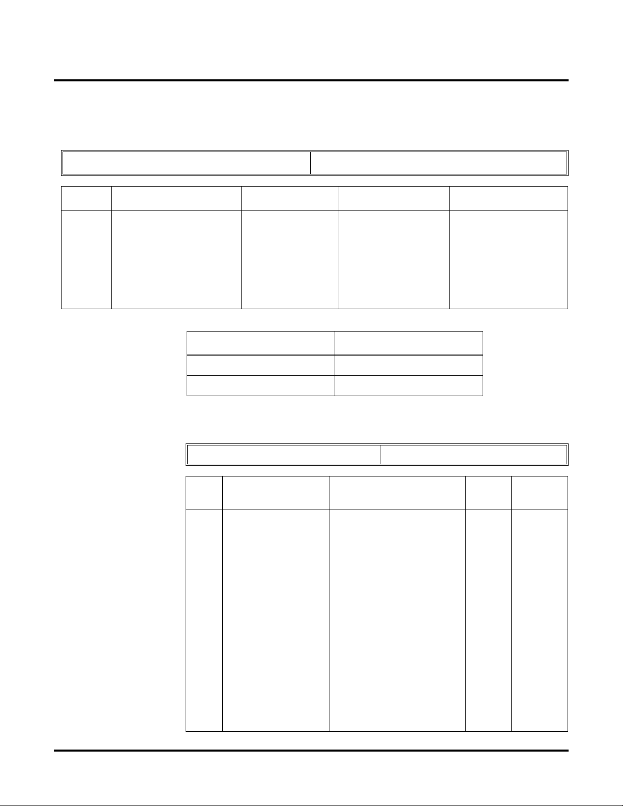
Aspire PCBs
Kind of available connection is show in following table.
Interface Description Note
2 ◆
ISDN Using Q.931 protocol, Basic rate interface
and Primary rate interfaces are available.
VoIP Using H.323 protocol for voice transmit
protocol.
When connecting a network using ISDN PCB, the PCBs must have the follo wing firmw are v ersion
or higher.
PCB Version
PRIU 2.0
BRIU 2.6
Using ISDN trunks provides up to 256 B-channel ports which can be used for Networking.
A PRIU or BRIU PCB is
required for connection.
A minimum version of firmware is required. Refer to the
table below.
A VOIPU PCB is required.
No specific firmware version
required.
Networking

Available Features
ARS/F-Route
Barge In
BLF Indication
Call Forwarding Override
Caller ID Display
Call Forwarding:
Immediately
Busy
No Answer
Both Ring
Call Forwarding, Follow Me
Call Forwarding, Off-Premise
Call Waiting / Camp On
Callback
Central Office Calls, Placing: Seizing a trunk in networked system
Conference
Department Step Calling
Direct Inward Dialing (DID)
Direct Inward Line (DIL)
Direct Inward System Access (DISA)
Department Calling
Hold
Hotline
Intercom: Change Voice/Signal Ring
Last Number Redial
Message W aiting
Paging
Park
Ringdown Extension, Internal/External
Selectable Display Messaging
Toll Restriction
Transfer
Voice Mail, Centralized
Feature Name
◆
Introduction
About Networking
Networking
3

Introduction
About Networking
4 ◆
Networking

About This Manual
Using This Manual
This manual is in three sections:
●
Section 1: Setting Up the Networking Feature
This section guides you step by step in setting up a basic Networking system. Y ou'll learn ho w
to:
●
Program the Aspire system for Networking
●
Program the Aspire system for Networking with Voice Mail
●
Set Up the Voice Mail for Networking
●
Section 2: Features
This section provides details on system features and how they work with a netw ork ed system.
●
Section 3: Programming Basics
This section describes the programming basics for the Aspire phone system.
Telephone Programming Instructions shows you how to enter the program’s data into sys-
tem memory. For example:
1. Enter the programming mode.
2. 15-07-01
15-07-01 TEL301
KY01 = *01
←←←← →→
→→
◆
Introduction
About This Manual
tells you to enter the programming mode, dial 150701 from the telephone dial pad. After you
do, you’ll see the message “15-07-01 TEL301” on the first line of the telephone display. This
indicates the program number (15-07), item number (01), and that the options are being set for
extension 301. The second row of the display “KY01 = *01” indicates that Key 01 is being
programmed with the entry of *01. The third row allows you to move the cursor to the left or
right, depending on which arrow is pressed. To learn how to enter the programming mode, see
How to Enter the Programming Mode (page 54).
Networking
5

Introduction
About This Manual
Unique Considerations
Simplifying Keyset Operation with One-Touch Keys...
A keyset user can access many features through Service Codes (e.g., Service Code *0 answers a
Message Waiting from a co-worker). To streamline the operation of their phone, a keyset user can
store these codes under One-Touch Keys. This provides one-button operation for almost any feature. To find out more, read the One-Touch Calling feature in your Software Manual.
Programmable Keys...
When reading an instruction using programmable keys, you will see a notation similar to (PGM 1507 or SC 851: 06). This means that the key requires function code 06, and you can program this
code through Program 15-07 or by dialing Service Code 851. Refer to the Programmable Function
Keys feature in your Software Manual if you need more information.
Using Handsfree...
The manual assumes each extension has Automatic Handsfree. This lets a user just press a line ke y
or CALL key to answer or place a call. For extensions without Automatic Handsfree, the user
must:
Lift the handset or press SPK for Intercom dial tone
Lift the handset or press SPK, then press a line key for trunk dial tone
◆ Read These Notes ◆
6 ◆ Networking

Setting Up The Networking Feature
Required System Programming
Setting Up The Networking Feature
Required System Programming
Section 1
Setting Up
The Networking Feature
Basic System Programming
The selection of an ISDN PRI, BRI, or VoIP PCB determines the type of programming you must do
on the Aspire. Refer to either the ISDN Networking or VoIP Networking section below.
ISDN Networking
10-03-01 : PCB Setup - ISDN Line Mode
➻
Determine the line mode of the ISDN. If Basic Rate Interface (BRI) is chosen, the setting
must be done for each line. The settings must match in all networked systems. The following
entries are acceptable for Networking.
ISDN Line Number 01-08
Item
No.
01 ISDN Line Mode 3 = Network Mode (Leased Line)
Networking ◆ 7
Item Input Data Default
1
4 = Network Mode (Interconnected Line)
5 = Interconnection (Interconnected Line,
Fixed Layer 1 Forced NT Mode)

Setting Up The Networking Feature
Required System Programming
➻ 10-03-03: PCB Setup - Connection Type
The connection type should be changed if Basic Rate Interface (BRI) is used. Only Point-toPoint connection (1) is available for system interconnection.
ISDN Line Number 01-08
Item
No.
03 Connection Type 0 = Point-to-Multipoint (not available for
Example:
Item Input Data Default
Networking)
1 = Point-to-Point
System – A System – B
1: Point-to-Point 1: Point-to-Point
➻ 10-03-10 : PCB Setup - Master/Slave System
Determine which system will be the master system and which one(s) will be the slave system(s). If one system is set as the Master, all the other systems must be set as the Slav e. Mak e
sure the switch on the ISDN PCB is set as follows: Master = S-Point, Slave = T-Point.
ISDN Line Number 01-08
Item
No.
10 Master/Slave System
(Network Mode Only)
Example:
System – A System – B
Item Input Data Default
0- Slave System
1- Master System
0
0
1: Master 2: Slave
➻ 10-03-11 : PCB Setup - Networking System Number
The Networking ID is used to select the access route. You can choose any number 0 to 50 (0
equals no operation). This ID is used when setting the numbering plan for the networked systems. The same ID number must be set in both 10-03-11 and 11-01. Refer to Numbering
Plan (page 12) for more on the numbering plan settings.
ISDN Line Number 01-08
Item
No.
10 Networking System Number
(Network Mode Only)
Example:
System – A System – B
Networking ID: 1 Networking ID: 1
8 ◆ Networking
Item Input Data Default
0-50 0

Setting Up The Networking Feature
Voice Over IP Networking
10-12-01 : NTCPU Network Setup - IP Address
➻
Select the IP address of the NTCPU (default: 172.16.0.10). A static IP address is required by
the NTCPU. The system must be reset in order for the change to take effect.
➻ 10-12-02 : NTCPU Network Setup - Subnet Mask
Select the Subnet Mask to be used by the IP server (default: 255.255.0.0).
Required System Programming
Item
No.
01 NTCPU
02 NTCPU
Item Input Data Default Conditions
IP Address
Subnet
Mask
1.0.0.1 - 126.255.255.254
128.1.0.1 -191.254.255.254
192.0.1.1 - 223.255.254.254
128.0.0.0
240.0.0.0
254.0.0.0
255.192.0.0
255.252.0.0
255.255.128.0
255.255.248.0
255.255.255.0
255.255.255.224
255.255.255.252
Example:
192.0.0.0
248.0.0.0
255.0.0.0
255.224.0.0
255.254.0.0
255.255.192.0
255.255.252.0
255.255.255.128
255.255.255.240
255.255.255.254
System – A System – B
IP Address: 172.16.0.10 IP Address: 172.16.0.11
224.0.0.0
252.0.0.0
255.128.0.0
255.248.0.0
255.255.0.0
255.255.224.0
255.255.254.0
255.255.255.192
255.255.255.248
255.255.255.255
172.16.0.10
255.255.0.0 The setting of SubnetMask is mistaken when
all Host Address are 0.
If the network section
is:
0,
127
128.0
191.255
192.0.0
223.255.255
The setting of SubnetMask is mistaken.
Subnet Mask: 255.255.0.0 Subnet Mask: 255.255.0.0
Networking ◆ 9
Setting Up The Networking Feature
Required System Programming
➻ 84-05-01 : VOIPU IP Address Setup - IP Address
For each VOIPU PCB, enter the IP address for the VOIPU PCB (default: slot 1=173.16.0.20,
slot 2 = 172.16.0.21, etc). The IP address should be increased according to the number of
VOIPU PCBs. This entry becomes invalid if Program 84-04 is set to "1" (DHCP enabled).
Slot Number 01-16
Item Input Data Default Description Related Program
IP
Address
1.0.0.1–126.255.255.254
128.1.0.1–191.254255.254
192.0.1.1–223.255.254.254
Example:
IP Address: 172.16.0.20 IP Address: 172.16.0.21
Subnet Mask: 255.255.0.0 Subnet Mask: 255.255.0.0
➻ 10-27 : IP System ID - IP Address
Set the System ID, IP address, and Call Procedure Port of the networked IP systems.
Item
No.
Slot 1: 173.16.0.20
Slot 2: 173.16.0.21
Slot 3: 173.16.0.22
Slot 4: 173.16.0.23
Slot 5: 173.16.0.24
Slot 6: 173.16.0.25
Slot 7: 173.16.0.26
Slot 8: 173.16.0.27
System – A System – B
System ID 01-50
Item Input Data Default
Set IP Address of
VoIPU PCB.
IP Address will be
increased in accordance with number of
slot.
84-04
This becomes invalid data
if Program 84-04 is set to
0:Disable.
Related
Program
01 IP Address
System ID is related
with the System ID in
the Numbering Plan
(Program 11-01-03).
When the digits are
analyzed and the system ID is determined
from the system data
set in the Numbering
Plan, the Networking
call will be sent to the
IP Address set in this
program.
The IP Address should
be the IP Address of
the peer NTCPU (Program 10-12-01).
10 ◆ Networking
1.0.0.1_126.255.255.254
128.1.0.1 _191.254.255.254
192.0.1.1 _223.255.254.254
0.0.0.0 11-01-03
10-12-01

Setting Up The Networking Feature
Required System Programming
02 Call Procedure Port
The Port Number
should be set with the
same value as the
H.225 setup port in
Program 84-02-33.
Example:
System – A System – B
System ID: 1 System ID: 1
IP Address: 172.16.0.20 IP Address: 172.16.0.21
Port: 1730 Port: 1730
1-65535 1730 84-02-33
➻ 10-20-01 : LAN Setup for External Equipment - TCP Port
Define the TCP port number for communicating to external equipment. The port number
defined should be the same in each networked system.
Type of external equipment 1- CTI Server
2- ACD MIS
3- - Reserve 4- Network Listener
5- SMDR
Item
No.
01 TCP Port 0-65535 External Device 1 = 7625
Example:
External Equipment: 4 External Equipment: 4
Item Input Data Default
External Device 2 = 7625
External Device 3 = 0
External Device 4 = 0
External Device 5 = 0
System – A System – B
Port: 30000 Port: 30000
➻ 84-02-35 : H.225, H.245 Information Basic Setup - Fast Start Mode
If VoIP is used for networking, the Fast Start option must be enabled.
Item
No.
35 Fast Start 0: Disable
Item Input Data Default
1: Enable
1
Networking ◆ 11

Setting Up The Networking Feature
Required System Programming
Numbering Plan
11-01-01 : System Numbering
➻
Set the system’s internal (Intercom) numbering plan and system ID to route to networked systems. The numbering plan assigns the first and second digits dialed and affects the digits an
extension user must dial to access other extensions and features, such as service codes and
trunk codes, within a networking node or to reach another node.
Consider using a "Unified Numbering Plan" for extensions. This gives every extension in the
network a unique extension number. The extension number can then be used to route a call to
the proper node. This also allows the same extension number to be dialed at an y node to reach
a given extension.
CAUTION
Improperly programming this option can adversely affect system operation. Make
sure you thoroughly understand the default numbering plan before proceeding. If you
must change the standard numbering, use the chart for System Numbering (page 79)
to keep careful and accurate records of your changes.
Before changing your numbering plan, use the PC Program or Web PC Program to
make a backup copy of your system’s data.
Changing the numbering plan consists of three steps:
1. Enter the digits you want to change.
2. Specify the length of the code you select to change.
3. Assign a function to the code selected.
Step 1: Enter the digit(s) you want to change
You can make either single or two digit entries. In the Dialed Number column in the System
Numbering (page 79) table, the nX rows (e.g., 1X) are for single digit codes. The remaining
rows (e.g., 11, 12, etc.) are for two digit codes.
● Entering a single digit affects all the Dialed Number entries beginning with that digit. For
example, entering 6 affects all number plan entries beginning with 6. The entries you make
in step 2 and step 3 below affect the entire range of numbers beginning with 6. (For
example, if you enter 3 in step 2 the entries affected would be 600-699. If you enter 4 in
step 2 below, the entries affected would be 6000-6999.)
● Entering two digits lets you define codes based on the first two digits a user dials. For
example, entering 60 allows you to define the function of all codes beginning with 60. In
the default program, only * and # use two-digit codes. All the other codes are single digit.
If you enter a two digit code between 0 and 9, be sure to make separate entries for all the
other two digit codes within the range as well. This is because in the default program all
the two digit codes between 0 and 9 are undefined.
Step 2: Specify the length of the code you want to change
After you specify a single or two digit code, you must tell the system how many digits comprise the code. This is the Number of Digits Required column in the System Numbering
(page 75) table. In the default program, all codes from 100-999 are three digits long. Codes
beginning with 0 are one digit long. Codes beginning with * are 3 digits long and codes beginning with # are 4 digits long.
12 ◆ Networking

Setting Up The Networking Feature
Required System Programming
Step 3: Assign a function to the code selected
After entering a code and specifying its length, you must assign its function. This is the Dial
Type column in the System Numbering (page 79) table. The choices are:
Dial Types Dial Type Description Related Program
0 - Not Used 1 Service Code 11-10 : Service Code Setup (for System Administrator)
11-11 : Service Code Setup (for Registration)
11-12 : Service Code Setup (for Service Access)
11-13 : Service Code Setup (for ACD)
11-14 : Service Code Setup (for HOTEL)
11-15 : Service Code Setup (Special access)
2 Extension Number 11-02 : Extension Numbers
11-04 : Virtual Extension Numbers
11-06 : 2PGDAD (ACI) Extension Numbers
11-07 : Department Calling Group Numbers
11-08 : 2PGDAD (ACI) Group Pilot Numbers
3 Trunk Access Code 11-09 : Trunk Access Code.
4 Special Trunk Access 11-09 : Trunk Access Code.
5 Operator Access 20-17 : Operator’s Extension
6 ARS/F-Route Access 44-xx
8 Networking 10-03 : PCB Setup
10-12 : NTCPU Network Setup
10-20 : LAN Setup for External Equipment
10-27 : IP System IP
● Changing the Dial Type for a range of codes can have a dramatic affect on how your sys-
tem operates. Assume, for example, the site is a hotel that has room numbers from 100-
399. In order to make extension numbers correspond to room numbers, you should:
- In Program 11-02, reassign extension numbers on each floor from 100 to 399.
(Other applications might also require you to change entries in Program 11-10 through
11-16.)
Example:
This example shows two separate extension numbers assigned for the networked systems.
System A dials 4xx to reach System B, while system B dials 3xx to reach System A.
System – A System – B
Dial “3x”:
• Digit “3”
• Type 2 (Intercom)
Dial “4x”:
• Digit “3”
• Type 8 (Networking)
• System ID “1”
Dial “3x”:
• Digit “3”
• Type 8 (Networking)
• System ID “1”
Dial “4x”:
• Digit “3”
• Type 2 (Intercom)
Networking ◆ 13

Setting Up The Networking Feature
Required System Programming
The following example shows a unified extension number assignment. All users dial a 4-digit
extension number (2xxx) to reach anyone within the network, regardless of which system the y
are connected. System A users have extension numbers 20xx, while system B users have
extension numbers 23xx.
Programming System – A System – B
Program 11-01 Dial “2”:
• 2x = Digit “0”
• 20 = Digit “4”, Type 2 (Intercom)
• 23 = Digit “4”, Type 8 (Network),
System ID “1”
• 7x = Digit “1”, Type 6 (F-Route)
Program 11-02 Port 1 = extension number 2001
Port 2 = extension number 2002
Port 3 = extension number 2003, etc.
Program 44-01-01 0 (Not Used) 0 (Not Used)
Program 44-02 Table 1 Table 2 Table 1 Table 2
Program 44-02-01 720@@ 723@@ 720@@ 723@@
Program 44-02-02 2 2 2 2
Program 44-02-03 1 2 1 2
Program 44-05 Table 1 Table 2 Table 1 Table 2
Program 44-05-01 255 101 101 255
Program 44-05-02 1 0 0 1
Dial “2”:
• 2x = Digit “0”
• 20 = Digit “4”, Type 8 (Network),
System ID “1”
• 23 = Digit “4”, Type 2 (Intercom)
• 7x = Digit “1”, Type 6 (F-Route)
Port 1 = extension number 2301
Port 2 = extension number 2302
Port 3 = extension number 2303, etc.
➻ Program 11-02-01 : Extension Numbering
Assign the extension numbers to the ports. The extension number can be up to eight digits
long. The first/second digit(s) of the number should be assigned in Program 11-01. This lets
an employee move to a new location (port) and retain the same extension number.
➻ 44-01-01 : System Options for ARS/F-Route - ARS/F-Route Time Schedule
Set this option to ‘0’ so that the F-Route table selected is determined only by the digits dialed
without any relation to the day or time of the call.
➻ 44-02-01 : Dial Analysis Table for ARS/F-Route Access - Dial
Set the number of digits to be analyzed by the system for ARS routing. Using the 4-digit
extension number example in Program 11-01-01, the entry would be: Analysis Table 1:
720@@; Analysis Table 2: 723@@.
➻ 44-02-02 : Dial Analysis Table for ARS/F-Route Access - Service Type
Select the Service Type (0=no setting, 1=extension call, 2=ARS/F-Route table, 3=Dial extension
analyze table). Using the 4-digit extension number example in Program 11-01-01, the entry would
be: Analysis Table 1: 2 (ARS/F-Route table); Analysis Table 2: 2 (ARS/F-Route table).
➻ 44-02-03 : Dial Analysis Table for ARS/F-Route Access - Additional Data
Enter the additional data required for the service type selected in Program 44-02-02, either the
number of digits to be deleted or the table number to be used. Using the 4-digit extension
number example in Program 11-01-01, the entry would be: 1 (delete 1 digit).
14 ◆ Networking

Setting Up The Networking Feature
Required System Programming
➻ 44-02-04 : Dial Analysis Table for ARS/F-Route Access - Dial Tone Simulation
If enabled (1), this option sends dial tone to the calling party once the routing is determined.
This may be required if the central office at the destination does not send dial tone. Using the
4-digit extension number example in Program 11-01-01, the entry would be: 0 (disabled).
➻ 44-05-01 : ARS/F-Route Table - Trunk Group Number
Select the trunk group number to be used for the outgoing ARS call (0-100, 101-150, 255 [0 =
No setting, 101-150 = Networking, 255 = Extension Call]). Using the 4-digit extension number example in Program 11-01-01, the entry would be: ARS/F-Route Table Number 1: Priority
Number 1, Trunk Group = 255; ARS/F-Route Table Number 2: Priority Number 1, Trunk
Group = 101.
➻ 44-05-02 : ARS/F-Route Table - Delete Digits
Enter the number of digits to be deleted from the dialed number (0-255 [255 = Delete all]).
Using the 4-digit extension number example in Program 11-01-01, the entry would be: ARS/
F-Route Table Number 1: Priority Number 1, Delete Digits = 1; ARS/F-Route Table Number
2: Priority Number 1, Delete Digits = 0.
➻ 44-05-03 : ARS/F-Route Table - Additional Dial Number Table
Enter the table number (defined in Program 44-06) for additional digits to be dialed (0-1000).
Using the 4-digit extension number example in Program 11-01-01, the entry would be: ARS/
F-Route Table Number 1: Priority Number 1, Additional Dial Number Table = 0; ARS/FRoute Table Number 1: Priority Number 1, Additional Dial Number Table = 0.
Networking ◆ 15

Setting Up The Networking Feature
Required System Programming
- For Your Notes -
16 ◆ Networking

Features
Features
Section 2
Features
Networking ◆ 17

Features
- For Your Notes -
18 ◆ Networking

Network Settings and Operation
Features
Network Settings and Operation
Refer to the Aspire Software Manual (P/N 0893200) for complete description and
programming information for the following featues. The information detailed here
applies only to the feature when used in a Networked system.
ARS/F-Route
When dialing the F-Route access code in an extension’s own system which is specified as Routing
to Networked system (Group 101-150), calls will be routed to the target system. The call will then
be analyzed by the F-Route table in the target system. As a result, the call will be analyzed for the
following:
● Outgoing call from trunk
● Extension access call
● Access to the other system
● No defined dial
Compared With Single System Configuration
In a single system with F-Route used, the dialing is analyzed when the call is initially dialed.
Operation
With the sample programming shown below, dialing the F-Route access number, which is defined
in the F-Route table (811300), the system calls extension number 300 within System 1 (System ID
1). The telephone’s display initially indicates the F-Route number in progress, then changes to
appear as an normal intercom call.
(Sample Programming)
Kind of setting System 1 System 2
PRG11-01-01
System Numbering
PRG44-02-
Dial analysis table for
F-Route access
PRG44-05-
System Numbering
Dial “7”
Digit “1” (1 digit)
Type “6” (F-Route)
01 “711300”
“711@@@” (using wildcard)
is available.
02 “2” (F-Routing) “2” (F-Routing)
03 Add Code = “1” Add Code = “1”
01 F-Route table-1
Trunk Group No. “101”
(Route to System ID 1)
Dial “7”
Digit “1” (1 digit)
Type “6” (F-Route)
“711300”
“711@@@” (using wildcard)
is available.
F-Route table-1
Trunk Group “255”
(Route to Intercom)
02 Delete Digit: 0 Delete Digit: 3
Networking ◆ 19

Features
Network Settings and Operation
Related Programs
Program Number Title
11-01 Numbering Plan
44-01 System Options for F-Route Service
44-02 Dial Analysis Table for F-Route Access
44-04 F-Route Selection for time schedule
44-05 F-Route T able
44-06 Additional Dial Table
44-07 Gain Table for F-Route Access
44-08 Time Schedule for F-Route Service
44-09 Weekly Schedule for F-Route Service
44-10 Holiday Schedule for F-Route Service
Barge In
Operation
Barge In is available in the Networking feature with the following options:
● Barge into a conversation between an extension’s own system and a networked system
● Barge into a conversation between callers in a networked system
● Barge into a call between two networked systems
Barge In can be used in either Monitor Mode (Silent Monitor) or Speech Mode (determined in
Program 20-13-10).
Barge In cannot barge into calls across the network in the following instances:
● Conference calls
● Off hook signaling a telephone in the other system
● Barge into an extension’s call without first calling the busy extension in the other system
To Barge In after calling a busy extension:
The call must be set up for about 10 seconds before you can Barge In.
Listen for busy/ring or busy tone.
1. Call busy extension.
2. Press Barge In key (PGM 15-07 or SC 851: 34).
20 ◆ Networking

Related Programs
Program Number Title
11-12-08 Service Code Setup (for Service Access) - Barge In
11-16-02 One Digit Service Code Setup - Barge In
20-13-15 Class of Service Options (Supplementary Service) - Barge In, Initiate
20-13-16 Class of Service Options (Supplementary Service) - Barge In, Receive
20-13-17 Class of Service Options (Supplementary Service) - Barge In Tone/
Call Forwarding
Call Forwarding Immediate / Busy / No Answer / Busy-No Answer / Both Ring options are available with the Networking feature.
Features
Network Settings and Operation
Display
With a networked system, when Call Forwarding enabled, there is a slight difference in the telephone’s display. With a single system, the extension name is displayed on the extension which has
Call Forwarding. With a networked system, the extension number is displayed.
Operation
To activate or cancel Call Forwarding:
To activate or cancel Call Forwarding:
1. Press idle CALL key (or lift handset) + Dial *2 .
OR
Press Call Forwarding key (PGM 15-07 or SC 851: code 16).
2. Dial Call Forwarding condition:
1 = Personal Answering Machine Emulation (then skip to step 4 - refer also to “Voice Mail”).
2 = Busy or not answered
4 = Immediate
6 = Not answered
7 = Immediate with simultaneous ringing (not for Voice Mail)
0 = Cancel
3. Dial destination extension, Voice Mail master number or press Voice Mail key.
4. Dial Call Forwarding type:
2 = All calls
3 = Outside calls only
4 = Intercom calls only
When you enable Call Forwarding, your Call Forwarding key flashes slowly. If you
don’t have a Call Forwarding key, DND flashes slowly.
Your DND or Call Forwarding (Station) Programmable Function Key flashes when
Call Forwarding is activated.
OR
Networking ◆ 21

Features
Network Settings and Operation
1. Press Call Forwarding key.
PGM 15-07 or SC 851: code 10 for Forward All Calls Immediately
PGM 15-07 or SC 851: code 11 for Forward when Busy
PGM 15-07 or SC 851: code 12 for Forward when Unanswered
PGM 15-07 or SC 851: code 13 for Forward Busy/No Answer
PGM 15-07 or SC 851: code 14 for Forward with Both Ringing
PGM 15-07 or SC 851: code 15 for Follow Me
PGM 15-07 or SC 851: code 16 for Forward to Station (forward type is selected at the
PGM 15-07 or SC 851: code 17 for Forward to Device
2. Dial 1 plus extension to enable; dial 0 to disable.
Once you activate Call Forwarding, only your Call Forwarding destination can place
an Intercom call to you.
3. Dial destination extension, Voice Mail master number or press Voice Mail key.
You’ll hear stutter dial tone when placing a new call.
Your Call Forwarding Programmable Function Key flashes when Call Forwarding is
activated.
Related Programs
time the option is set by the user)
Program Number Title
11-11-01 Service Code: Call Forward – Immediate
11-11-02 Service Code: Call Forward – Busy
11-11-03 Service Code: Call Forward – No Answer
11-11-04 Service Code: Call Forward – Busy/No Answer
11-11-05 Service Code: Call Forward – Both Ring
11-11-06 Service Code: Call Forwarding (Select Option)
20-11-01 Call Forward – Immediate Class of Service
20-11-02 Call Forward – Busy Class of Service
20-11-03 Call Forward – No Answer Class of Service
20-11-04 Call Forward – Both Ring Class of Service
Call Forwarding / Do Not Disturb Override
The extension user may be able to call an extension which has Call Forwarding or Do Not Disturb
set.
Operation
To override an extension’s Call Forwarding or Do Not Disturb:
1. Call the forwarded or DND extension.
2. Press Override key (PGM 15-07 or SC 851: 37).
22 ◆ Networking

Related Programs
Program Number Title
11-12-01 Service Code Setup (for Service Access) : Call Forwarding / Do Not
Disturb Ovveride
11-16-06 Single Digit Service Code Setup : DND/Call Forward Override
15-07-01 Programming Function Keys
20-06-01 Class of Service for Extensions
20-13-04 Class of Service Options (Supplementary Service) - Call Forwarding/
DND Overrride
Call Forward, Off-Premise
Off-Premise Call Forwarding allows an extension user to forward their calls to an off-site location.
This feature works the same in a networked system as it ddoes a single system.
Features
Network Settings and Operation
Operation
To activate Call Forwarding Off-Premise
1. At keyset, press idle CALL key + Dial *4 .
OR
Press Call Forward (Device) key (PGM 15-07 or SC 851: 17)
OR
At SLT, lift handset Dial *4 .
2. Dial 6 + trunk access code.
Trunk access codes are 9 (ARS/Trunk Group Routing), 804 + Line Group (1-9, 01-99
or 001- 100) or #9 + Line number (e.g., 05 or 005 for line 5.
3. Dial the outside number to which your calls should be forwarded.
4. (Keyset only) Press HOLD.
5. Press SPK (or hang up at SLT) to hang up if you dialed *4 in step 1.
Your DND or Call Forwarding (Device) Programmable Function Key flashes.
To cancel Call Forwarding Off-Premise
1. At keyset, press idle CALL key + Dial *4 .
OR
Press Call Forward (Device) key (PGM 15-07 or SC 851: 17)
OR
At SLT, lift handset and dial *4 .
2. Dial 6 + HOLD.
3. Press SPK (or hang up at SLT) to hang up if you dialed *4 in step 1.
Your DND or Call Forwarding (Device) Programmable Function Key stops flashing.
Networking ◆ 23

Features
Network Settings and Operation
Related Programs
Program Number Title
13-01 Abbreviated Dial Function Setup
14-05 Trunk Group
14-06 Trunk Group Routing
21-02 Trunk Group Routing for Extensions
21-16 Trunk Group Routing for Networking
Call Forwarding with Follow Me
The extension user can program Call Forward Follow-Me to extension in a networked system.
When the extension with the Follow Me setting receives an incoming call, both the original extension and the programmed destination extension starts ringing.
With a networked system, when Call F orward F ollo w-Me is enabled, there is a slight difference in the
telephone’s display. With a single system, the destination e xtension displays the e xtension name for the
phone with Follow-Me enabled. With a networked system, the extension number is displayed.
Operation
To activate Call Forward Follow Me:
1. At a keyset other than your own, press idle CALL key and dial *2 .
OR
Press Call Forward (Station) key (PGM 15-07 or SC 851: 15).
OR
At SLT other than your own, lift handset and dial *2 .
2. Dial 3 + Dial your own extension number (i.e., the source).
3. Dial Call Forwarding Type:
2 = All Calls
3 = Outside calls only
4 = Intercom calls only
4. SPK (or hang up at SLT) if you dialed *2 in step 1.
Your Call Forwarding (Station) Programmable Function Key flashes when Call For-
warding is activated.
To cancel Call Forward Follow Me:
1. At keyset, press idle CALL key and dial *2 .
OR
Press Call Forward (Station) key (PGM 15-07 or SC 851: 15).
OR
At SLT, lift handset and dial *2 .
2. Dial 0.
3. SPK (or hang up at SLT) if you dialed *2 in step 1.
Your Call Forwarding (Station) Programmable Function Key goes out.
24 ◆ Networking

Related Programs
Program Number Title
11-11-07 Service Code of Follow Me
11-11-06 Call Forwarding (Select Option)
Call Waiting / Camp On
With Call Waiting, an extension user may call a busy extension and wait in line (Camp-On) without
hanging up. When the user Camps-On, the system signals the busy extension with two beeps indicating the waiting call. The call goes through when the busy extension becomes free. Call Waiting
helps busy extension users know when the y ha ve additional w aiting calls. It also lets callers wait in
line for a busy extension without being forgotten.
With a networked system, camping on to an idle e xtension and T runk Queuing/Camp On for a trunk
port are not supported.
With a networked system, when Call Waiting/Camp On is enabled, there is a slight difference in the
telephone’s display. With a single system, the target extension’s name is displayed on thephone
which has enabled Call Waiting. With a networked system, the extension number is displayed.
Features
Network Settings and Operation
Operation
To Camp-On to a busy extension:
1. Call busy extension.
2. Dial 2 or press Camp-On key (PGM 15-07 or SC 851: 35).
3. Do not hang up.
To Camp-On to a trunk, see Trunk Queuing.
To cancel a Camp-On request:
1. Hang up.
2. At keyset, press idle CALL key and dial 870.
OR
At keyset, press Camp-On key (PGM 15-07 or SC 851: 35).
OR
At single line set, lift handset and dial 870.
Related Programs
Program Number Title
11-12-05 Service Code: Setting Camp On
11-12-06 Service Code: Cancelling Camp On
11-16-05 One-Digit Service Code: Camp On
Networking ◆ 25

Features
Network Settings and Operation
Caller ID Display
Caller ID information can be sent to incoming target extension in a networked system and sho w the
Caller ID on the phone’s display. The ABB Name is also shown on LCD by searching ABB table.
Caller ID, however, cannot be shown in a networked system for incoming trunks defined as normal
(0) in Program 22-02.
Operation
No change.
Related Programs
➻ 20-09-02 : Class of Service Options (Incoming Call Service) - Caller ID Display
Define the option whether display Caller ID or not in each station port.
Item
No.
Item
Input
data
COS
01-14
Default
COS 15
02 Caller ID Display
Enables/disables the Caller ID display at an
extension.
0-Off
1-On
00
➻ 20-09-02 : Class of Service Options (Incoming Call Service) - Sub-Address Identification
Define whether an extension displays the Caller Sub-Address.
Default
Item
No.
03 Sub Address Identification
Define whether an extension displays the
Caller Sub-Address.
Item
Input
data
0-Off
1-On
COS
01-14
00
COS 15
26 ◆ Networking

Features
Network Settings and Operation
➻ 13-04 : Abbreviated Dialing Number and Name
Define the abbreviated dialing number and name. The ABB name will be shown on a phone’s
LCD when the ABB table has a matching number with the incoming Caller ID. The common
abbreviated number table is used to search for a match.
Item
No.
01 Abbreviated Dialing
Data
02 Name Max. 12 Characters No Setting
Item Input Data Default
1-9, 0, *, #,
Pause (Press line key 1),
Recall/Flash (Press line key 2),
@ for Additional Digit for ISDN
Functionality (Press line key 3)
(max. 24 digits)
No Setting
Central Office Calls, Placing: Seizing a trunk in a networked system
The system allows a user to seize a trunk in a networked system using the following methods:
Method of Outgoing Available Note
Specified Trunk Access (#9 + the trunk number) N
Specified Trunk Group Access (804 + group number) N
Trunk Route Access (9) Y
ARS/F-Route See ARS/F-Route
Related Programs
The following example indicates the setting required to seize the trunk in a networked system
(Extension in System A tries to make an external call using a trunk in System B).
Program System – A System – B
Program 14-06-01
Trunk Group Routing
Program 21-02-01
Trunk Group Routing
for Extensions
Program 21-16-01
Trunk Group Routing
for Networking
Route 1
101 (Route to SystemID 1)
Extension 301 (which make a
call via networking)
1 (Route 1)
This setting is referenced in
Program 14-06-01
Route 1
1 (Route to Trunk Group 1)
System ID 1
Route 1
This setting is referenced in
Program 14-06-01
Networking ◆ 27

Features
Network Settings and Operation
Conference
The user can create a Conference call to include a user in a networked system.
Operation
To establish a Conference:
Keyset
1. Establish Intercom or trunk call.
2. Press CONF or Conference key (PGM 15-07 or SC 851: 07).
3. Dial extension you want to add.
OR
Access outside call
OR
Retrieve call from Park orbit.
T o get the outside call, you can either press a line k ey or dial a trunk/trunk gr oup code.
You can optionally go back to step 2 to add more parties to your Conference.
4. When called party answers, press CONF or Conference key twice.
If you cannot add additional parties to your Conference, you have exceeded the sys-
tem’s Conference limit.
5. Repeat steps 2-4 to add more parties.
Single Line Set / 2-Button Telephone
1. Establish Intercom or trunk call.
2. Single Line Set
Hookflash and dial #1.
2-Button Telephone
Press HOLD and dial #1.
3. Dial extension you want to add.
OR
Access trunk call.
OR
Retrieve call from Park orbit.
4. Single Line Set
Hookflash and repeat step 3 to add more parties.
OR
Hookflash twice to set up the Conference.
2-Button Telephone
Press HOLD and repeat step 3 to add more parties.
OR
Press HOLD twice to set up the Conference.
If you cannot add additional parties to your Conference, you have exceeded the sys-
tem’s Conference limit.
28 ◆ Networking

Related Programs
Program Number Title
15-07-01 Programming Function Keys - Conference (code 07)
20-06-01 Calls of Service for Extensions
20-13-08 Class of Service Options (Supplementary Service) - Conference
Department Calling
Department Group access is available via Networking. When the extension at System A tries to
make a Department Call to System B, System A should have a numbering plan which defines the
Department Access code at System-B (must be defined as dial type 8, Networking in Program 1101 : System Numbering).
The following Department Calling options are supported with the Networking feature.
Features
Network Settings and Operation
Program Number Mode Same as Single System
16-01-02 Department Calling Cycle Yes
16-01-03 Department Routing When Busy Yes
16-01-04 Hunting Mode No
16-01-05 All Ring Mode When a call is transferred to a
Department Group with All Ring,
there is a difference in operation. In a
single system, an extension within
the same system can transfer a call to
a Department Group and the call will
ring an extension within the Department Group once the transferring
user hangs up. In a networked system, the transfer will not go through
and the call will recall the extension
performing the transfer.
16-01-06 STG Withdra w Mode No
16-01-07 Call Recall Restriction for STG No
16-01-08 Maximum Queuing Number No
16-01-10 Enhanced Hunting Mode No
Operation
1. When dialing the Department access code for the networked system, the call is dialed in the
the same way as the networking access code dialing the networked system.
2. A Department Call from the outgoing system will be routed to an available extension in the
Department Group.
Networking ◆ 29

Features
Network Settings and Operation
Related Programs
Program Number Title
11-07-01 Department Group Pilot Numbers
16-01 Department Group Basic Data Setup
16-02-01 Department Group Assignment for Extensions
22-07-01 DIL Assignment
Department Step Call
After calling a busy Department Calling Group member in a networked system, an extension user
can have Department Step Calling Quickly call another member in the group.
Operation
To make a Step Call:
You step through Extension Groups set in Program 16-02.
1. Place call to busy Department Group member.
OR
Place call to Department Group pilot number.
2. Dial #.
OR
Press Step Call key (PGM 15-07 or SC 851: 36).
3. Repeat step 2 to call other Department Group members.
Related Programs
Program Number Title
11-12-07 Service Code Setup (for Service Access) - Step Call
11-16-01 Single Digit Service Code Setup - Step Call
20-06-01 Class of Service for Extensions
20-08-12 Class of Service Options (Outgoing Call Service) - Department Step
Calling
30 ◆ Networking

Direct Inward Dialing (DID)
An incoming DID call can be routed to an extension in a networked system.
Operation
For incoming DID calls, the system refers to Program 22-11 : DID T ranslation Number Con v ersion
to determine how to route the call. If the number is determined to be in the networked system, the
call will be routed to the proper system node.
The timer value is determined by the system data at the incoming trunk side if the incoming DID
call is transferred to a ring group due to the no-answer timer expiring.
Related Programs
Program Number Title
22-02 Incoming Service Type
22-09 DID Basic Data Setup
Features
Network Settings and Operation
22-10 DID Conversion Area Setup
22-11 DID Conversion Table Data Setup
22-12 DID Transferred Destination Setup
Direct Inward Line (DIL)
A Direct Inward Line (DIL) is a trunk that rings an extension, virtual extension or Department
Group directly. Since DILs only ring one extension or group (i.e., the DIL destination), employees
always know which calls are for them. For example, a company operator can have a Direct Inward
Line for International Sales Information. When outside callers dial the DIL’s phone number, the
call rings the operator on the International Sales line key. The DIL does not ring other extensions.
The outside party can call an extension at a networked system, if the DIL trunk is set to route to the
other system.
Operation
1. An outside caller places a call to a DIL trunk.
2. The call will be routed to the networked system if the DIL target is defined as an extension in
the networked system in Program 22-07 : DIL Assignment.
Related Programs
Program Number Title
22-02 Incoming Service Type Setup
22-07 DIL Assignment
22-08 Second IRG Setup for Unanswered DIL/IRG
Networking ◆ 31

Features
Network Settings and Operation
Direct Inward System Access (DISA)
Networking allows DISA callers to place a call to an extension in a networked system. Some system features can also be accessed from the networked system. The Class of Service is determined
by the password entered by the DISA caller. The password table is referred to by the system on the
incoming trunk side.
The Networking feature allows the following DISA services as allo wed in Program 20-14 : Class of
Service Options for DISA/E&M.
Program Number Service Name Available
20-14-02 Trunk Route Access Yes
20-14-03 Trunk Group Access No
20-14-04 Common Abbreviated dialing No
20-14-05 Operator access Yes
20-14-06 Internal Paging No
20-14-07 External Paging Yes
20-14-08 Specified trunk access No
20-14-09 Forced trunk disconnect No
20-14-10 Call Forward setting No
20-14-11 Break In No
Operation
To place a DISA call into the system (from any 2500 type telephone):
1. Dial the telephone number that rings the DISA trunk.
2. Wait for the DISA trunk to automatically answer with a unique dial tone.
3. Dial the 6-digit DISA password (access code).
4. Wait for a second unique dial tone.
5. Dial an extension (301-556).
OR
Dial 9 for Trunk Group Routing or ARS.
OR
Dial Alternate Trunk Route Access Code (if enabled).
OR
Dial #9 + a trunk number (1-200) for an outside call.
OR
Dial 0 for the operator.
OR
Dial 803 + an External Paging Zone number (1-8 or 0 for All Call).
If the received digits are analyzed as a networked extension number, the call is routed
to the proper network node.
32 ◆ Networking

Network Settings and Operation
Related Programs
Program Number Title
20-14 Class of Service Options for DISA/E&M
22-02 Incoming Service Type Setup
25-01 DID/DISA Line Basic Data Setup
25-02 DID/DISA VRS Error Message
25-03 DID/DISA Transfer Ring Group with Incorrect Dialing
25-04 DID/DISA Transfer Ring Group with No Answer/Busy
25-05 DID/DISA Error Message Setup
25-06 DID/DISA One-Digit Code Attendant Setup
25-07 System Timers for DID/DISA
25-08 System timer for DID/DISA Service
Features
Hold
25-09 Class of Service for DISA User
25-10 Trunk Group Routing for DISA
25-11 Toll Restriction Class for DISA
25-12 Individual Trunk Group Routing for DISA
25-13 System Option DISA Service
This feature is available with no changes in programming or operation.
Networking ◆ 33

Features
Network Settings and Operation
Hotline / Direct Station Selection (DSS)
An extension user can have a Hotline key to a networked extension. The Hotline or DSS console
keys can display the status lamp indication of an extension in a networked system. The lamp status,
however, is not displayed in real time and is updated at the interval defined in system programming.
Only shows the status of an extension at other system. Lamp status is not update in real time. Status
will be updated in the time interval specified in Program 20-01-04.
Operation
To place a call to your Hotline partner:
1. Press Hotline key (PGM 15-07 or SC 851: 01 + partner’s extension number)
You can optionally lift handset after this step for privacy.
To transfer your outside call to your Hotline partner:
1. Press Hotline key.
2. Announce call and hang up.
OR
Hang up to have the call wait at your Hotline partner unannounced.
If unanswered, the call recalls like a regular transferred call.
To answer a call from your Hotline partner:
1. If you hear two beeps, speak toward phone.
OR
1. If your telephone rings, lift handset.
Calling an extension from your DSS Console:
1. (Optional for 110-Button Consoles) Press EXT.1 or EXT.2 to select the range.
2. Press DSS Console key.
If the call voice-announces, you can make it ring by dialing 1.
If you don’t have Handsfree, you must lift handset to speak.
Related Programs
Program Number Title
20-01-04 System Options - Network BLF Indication
20-02-03 System Options for Multi-Line Telephones - BLF Control
20-13-06 Class of Service Options (Supplementary Service) - Automatic Off Hook
Signaling
20-06-01 Class of Service for Extensions
30-05-01 DSS Console Lamp Table
34 ◆ Networking

Intercom
Operation
Features
Network Settings and Operation
An extension user can make an intercom call to a networked system if the networked e xtensions are
defined with the Network Access Code (Program 11-01, Dial Type = 8)
A user can change the signaling type for the intercom call they place to either a voice announce or
ringing call to extension in a networked system.
To place an Intercom call:
1. At keyset, press idle CALL key.
OR
At single line telephone, lift handset.
2. Dial extension number (or 0 for your operator).
Your call may voice-announce or ring the called extension. Dial 1 to change the way
your call alerts the called extension.
If the extension you call is busy or doesn’t answer, you can dial another extension
without hanging up.
Related Programs
Program Number Title
11-12-06 Service code of Voice/Signal Change
11-16-03 One digit service code of Voice/Signal Change
20-06-01 Class of Service for Extensions
20-08-01 Class of Service Options (Outgoing Call Service) - Intercom Calls
Networking ◆ 35

Features
Network Settings and Operation
Last Number Redial
Last Number Redial allows an extension user to quickly redial the last number dialed. When used
with a networked system, the system can use the same trunk on which the call was originally
placed, even if the trunk is a trunk in another system.
Operation
To redial your last call:
1. Without lifting the handset, press LND.
The last dialed number is displayed.
2. To redial the last number, press #.
OR
Search for the desired number from the Redial List by pressing the LND or VOLUME ▲ or
VOLUME ▼ keys.
3. Lift the handset or press SPK to place the call.
The system automatically selects a trunk from the same gr oup as your original call and
dials the last number dialed.
OR
1. At keyset, press idle line key (optional).
The system automatically selects a trunk from the same group as your original call.
2. Press LND.
OR
1. At keyset, press idle CALL key.
OR
At single line telephone, lift handset.
2. Dial #5.
The system automatically selects a trunk from the same gr oup as your original call and
dials the last number dialed.
Related Programs
Program Number Title
11-12-12 Service Code Setup (for Service Access) - Last Number Dial
15-02-13 Multi-Line Telephone Basic Data Setup - Redial List Mode
20-06-01 Class of Service for Extensions
36 ◆ Networking

Message Waiting
This feature can be used when placing an intercom call to a networked extension and receiv es either
no answer or hears a busy tone.
With a networked system, when a Message Waiting has been left, there is a slight dif ference in the telephone’s display. With a single system, the e xtension’s name which left the message is displayed. With a
networked system, the extension number is displayed.
Operation
To leave a Message Waiting:
1. Call busy or unanswered extension.
2. Dial 0 or press Message Waiting key (PGM 15-07 or SC 851: 38)
3. Hang up.
To answer a Message Waiting:
1. At a keyset, press idle CALL key and dial *0.
OR
Press Message Waiting key (PGM 15-07 or SC 851: 38).
OR
At single line telephones, lift the handset and dial *0.
automatically leave them a message.
“Voice Mail” mailbox or a new “General Message”. Go to “To check your messages” below.
Features
Network Settings and Operation
With keyset phones, the MW LED lights.
When you have a message, your MW LED flashes fast for keysets.
If the called extension doesn’t answer, dial 0 or press your Message Waiting key to
Normally, your MW LED goes out. If it continues to flash, you have ne w messag es in your
Related Programs
Program Number Title
11-11-09 Service Code Setup (for Setup/Entry Operation) - Answer Message
Waiting
11-11-10 Service Code Setup (for Setup/Entry Operation) - Cancel All Messages
Waiting
11-11-11 Service Code Setup (for Setup/Entry Operation) - Cancel Message
Waiting
11-16-07 Single Digit Service Code Setup: Message Waiting
20-13-07 Class of Service Options (Supplementary Service) - Message Waiting
Networking ◆ 37

Features
Network Settings and Operation
Paging
An extension user can make internal or external pages to a networked system. Paging to a networked system can only be activated by dialing a service code and the target network’s system ID.
Operation
To Make an Internal Page
1. Dial 801.
2. Dial # and the system ID.
The system ID must be dialed as 2 digits (ex: #02).
3. Dial the Paging Zone number (00-64).
Dialing 00 calls All Call External Paging.
4. Make announcement to the networked system.
5. Press SPK to hang up.
To Make an External Page
1. Dial 803.
2. Dial # and the system ID.
The system ID must be dialed as 2 digits (ex: #02).
3. Dial the Paging Zone number (0-9).
Dialing 0 calls All Call Internal Paging.
4. Make announcement to the networked system.
5. Press SPK to hang up.
To Make a Combined Page
1. Dial *1.
2. Dial # and the system ID.
The system ID must be dialed as 2 digits (ex: #02).
3. Dial the Paging Zone number (0-9).
Dialing 0 calls All Call Combined Paging.
4. Make announcement to the networked system.
5. Press SPK to hang up.
38 ◆ Networking

Network Settings and Operation
Related Programs
Program Number Title
11-12-19 Service Code Setup (for Service Access) - Internal Group Paging
11-12-20 Service Code Setup (for Service Access) - External Paging
11-12-24 Service Code Setup (for Service Access) - Combined Paging
31-01 System Options for Internal/External Paging
31-02 Internal Paging Group Assignment
31-03 Internal Paging Group Settings
31-04 External Paging Zone Group
31-07 Combined Paging Assignment
Features
Park
Park places a call in a waiting state (called a Park Orbit) so that an extension user may pick it up.
Any extension user who is in the same Park Group as the extension which placed the call in Park
can answer the call. This includes extension users in a networked system. For example, when an
extension user in Park Group 3 within System A places a call in Park, the extension users in Park
Group 3 at any connected system can retrieve the call by pressing the flashing park key or dialing a
service code.
With a single system, when two users within the same Park Group try to place a call in the same
page zone at the same time, one user will get the zone while the other user’s call will either ring
back or it will remain an active call, depending on how the park zone was accessed. With Networking, if both users try to access the same zone, one user will get the zone, while the other will hear
ringback, at which time they can park the call in a different zone.
Operation
To Park a call in a system orbit:
You can Park Intercom or trunk calls.
1. Press Park key (PGM 15-07 or SC 852: *04 + orbit).
The Park key LED lights.
If you hear busy tone, the orbit is busy. Try another orbit.
2. Use Paging to announce call.
3. Press SPK to hang up.
If not picked up, the call will recall to you.
OR
1. At keyset or 2-Button telephone, press HOLD.
OR
At a 500/2500 single line telephone, hookflash.
2. Dial #6 and the Park orbit (1-64).
If you hear busy tone, the orbit is busy. Try another orbit.
Networking ◆ 39

Features
Network Settings and Operation
3. Use Paging to announce call.
4. Press SPK to hang up.
If not picked up, the call will recall to you.
Note: The parked call recalls after the Park Hold Time (Program 24-01-06). The call
rings the extension to which it recalled for the Hold Recall Callback Time (Program 2401-02). The call then goes on Hold for the Park Hold Time - then recalls again for the
Hold Recall Callback Time. The call continues to cycle between Hold and recall until the
extension user answers the call or the outside party hangs up.
To pick up a parked call:
1. Lift handset.
2. Press Park key (PGM 15-07 or SC 852: *04 + orbit).
OR
1. At keyset or 2-Button telephone, press idle CALL key.
OR
At single line telephone, lift handset.
2. Dial *6 and the Park orbit (1-64).
Related Programs
Program Number Title
11-12-31 Service Code Setup (for Service Access) - Placing a Call in Park
11-12-32 Service Code Setup (for Service Access) - Retrieving Call from Park
20-11-19 Class of Service Options (Hold/Transfer Service) – Normal/Extended Park
If enabled, the recall timer set in Program 24-01-07 is used. If this option
is disabled, the timer in Program 24-01-06 is used.
24-01-06 System Options for Hold - Park Hold Recall Timer – Normal
24-01-07 System Options for Hold - Park Hold Recall Timer – Extended
24-03-01 Park Group
Ringdown Extension, Internal/External
A networked system can have a phone defined as a Ringdo wn Extension to dial either an internal or
external number.
Operation
To place a call if your extension has ringdown programmed:
1. Lift handset.
If you want to place a trunk call, press a line key before lifting the handset.
Depending on the setting of your ringdown timer, you may be able to dial an Intercom
call before your ringdown goes through.
If the destination has Handsfree Answerback enabled, your call will voice announce.
If the destination has Forced Intercom Ringing enabled, your call will ring.
40 ◆ Networking

Related Programs
Program Number Title
20-06-01 Class of Service for Extensions
20-08-09 Class of Service Options (Outgoing Call Service) - Hotline/Extension
Ringdown
21-01-09 System Options for Outgoing Calls - Ringdown Extension Timer
21-11-01 Extension Ringdown (Hotline) Assignments
Selectable Display Messaging
An extension user can select a preprogrammed Selectable Display Message for their extension.
This message will be displayed on an incoming intercom caller’s LCD when the y call the extension
in a networked system.
Operation
Features
Network Settings and Operation
To select a message:
1. Press idle CALL key + dial *4.
OR
Press Call Forward (Device) key (PGM 15-07 or SC 851: 17).
OR
Press idle CALL key + press Text Message key (PGM 15-07 or SC 851: 18) + enter digits to
append, if needed + SPK to hang up. Skip the remaining steps.
2. Dial 3 + Message number (01-20).
Use VOL ▲ or VOL ▼ to scroll through the messages.
3. (Optional for messages 1-8 and 10)
Dial the digits you want to append to the message.
Y ou can append messa ges 1-8 and 10 with digits (e .g., the time when you will be bac k).
You enter the time in 24-hour format, but it displays in 12-hour format.
4. Press SPK to hang up.
To cancel a message:
1. Press idle CALL key + dial *4.
OR
Press Call Forward (Device) key (PGM 15-07 or SC 851: 17).
OR
Press idle CALL key + press Text Message key (PGM 15-07 or SC 851: 18) + SPK to hang
up.
2. Dial 3.
3. Press SPK to hang up.
Networking ◆ 41

Features
Network Settings and Operation
Related Programs
Program Number Title
20-13-19 Class of Service Options (Supplementary Service) - Selectable Display
Messaging
20-16 Selectable Display Messages
Toll Restriction
Toll Restriction limits the numbers an extension user may dial. The Toll Restriction Class of Service is received the calling extension’s system, but the T oll Restriction table is used from the system
which has the outgoing trunk.
Since the restriction table is used for the system which has the outgoing trunk, the definition of the
Class of Service may be different, unless all Toll Restriction Classes of Service and Toll Restriction
Tables are defined the same between systems.
Operation
Example:
The extension user in System A, which has a Toll Restriction Class 2, dials an outside party after
seizing a trunk from a networked system (System B). The receiv ed digits are compared to the Class
2 Restriction Table in System B. The call is then either allowed or rejected based on this table.
Related Programs
Program Number Title
21-04 Toll Restriction Class Assignment for Extensions
21-05 Toll Restriction Class Setup
21-06 Toll Restriction Table Setup
42 ◆ Networking

Transfer
Operation
Features
Network Settings and Operation
The following types of Transfer are available with Networking:
● Screened Transfer
● Unscreened Transfer
● Transfer Without Holding (transfer to busy extension)
Transferring Trunk Calls
To Transfer a trunk call to a co-worker’s extension:
1. At keyset or 2-Button telephone, press HOLD.
OR
At 500/2500 single line telephone, hookflash.
You hear Transfer dial tone.
2. Dial co-worker’s extension number.
If the extension is busy or doesn’t answer, you can dial another extension number or
press the line key to return to the call. In addition, you may be able to hang up and have
the call Camp-On.
SLT users can r etrieve the call by pr essing hookflash. If a call has been transferr ed and
the 500/2500 user has hung up the handset, the call be can retrieved by dialing ** and the
extension number to which it had been transferred.
3. Announce call and hang up.
If you don’t have A utomatic On Hook Transfer, you must press CONF or your Transfer
Programmable Function Key to Transfer the call.
If your co-worker doesn’t want the call, press the flashing line key to return to the call.
SLT users can r etrieve the call by pr essing hookflash. If a call has been transferr ed and
the 500/2500 user has hung up the handset, the call be can retrieved by dialing ** and the
extension number to which it had been transferred.
If you don’t want to screen the call, hang up without making an announcement.
Transferring Without Holding
To Transfer without holding (keyset only):
1. Lift handset.
2. Press busy line key.
3. When original caller hangs up, you are connected.
Networking ◆ 43

Features
Network Settings and Operation
Transferring Intercom Calls
To Transfer your Intercom call:
1. At keyset, press HOLD.
OR
At single line telephone, hookflash.
2. Dial extension to receive your call.
If the extension is busy, doesn’t answer or does not want the call, you can dial another
extension number or press the lit CALL key to return to the call. In addition, you may be
able to hang up and have the call Camp-On.
SLT users can r etrieve the call by pr essing hookflash. If a call has been transferr ed and
the 500/2500 user has hung up the handset, the call be can retrieved by dialing ** and the
extension number to which it had been transferred.
3. Announce your call and hang up.
With Automatic On Hook Transfer
When you hang up, the call is automatically transferred.
Without Automatic On Hook Transfer
You must press your Transfer Programmable Function Key to Transfer the call.
To Transfer the call unscreened, press your T ransfer Programmable Function Key and
hang up without making an announcement.
Related Programs
Program Number Title
20-11-06 Class of Service Options (Hold/Transfer Service) - Unscreened Transfer
20-11-07 Class of Service Options (Hold/Transfer Service) - Transfer Without
Holding
20-11-08 Class of Service Options (Hold/Transfer Service) - Transfer Display
20-11-18 Class of Service Options (Hold/Transfer Service) - No Recall
24-02-01 System Options for Transfer - Busy Transfer
44 ◆ Networking

Network Settings and Operation
Voice Mail, Centralized Attendant Service
Networking will support the use of a single voice mail for the entire network. A user may call into
the voice mail from anywhere in the network and perform most functions as if the voice mail were
located on their premises. Currently, only the use of an external voice mail is supported for cen-
tralized voice mail.
With a networked system, when voice mail is busy, there is a slight difference in the telephone’s
display. With a single system, the extension calling a busy voice mail will see WAITING VOICE
MAIL on their display. With a networked system, the extension will display CALLING XXX
(XXX = extension number).
The system allows both a local voice mail pilot number and a centralized voice mail pilot number to
be assigned. Define the Department Group for the local voice mail pilot number in Program 45-0101 (assign the pilot number to each Department Group using Program 11-07-01). Use Program 4501-02 to assign the voice mail master name for the local voice mail.
Program 45-01-07 is used to define the pilot number of the centralized voice mail. Program 45-0108 sets the Department Group and Program 45-01-09 sets the voice mail master name for the centralized voice mail.
Features
Operation
Pilot Call
When the extension in System B dials the centralized voice mail access number (Program 45-01-
07), they connect to the voice mail in their own system (Program 45-01-08). It is not possible for
the user to access the voice mail in System A.
Service Codes
When the voice mail service code (Program 11-12-51) is dialed, the system calls either the voice
mail at the same site as the user, or if the centralized voice mail access number is defined in Program 45-01-07, then the centralized voice mail is called.
One-Digit Service Code
If an extension user hears either a busy signal or a ring back tone when placing an intercom call and
dials the one-digit service code for voice mail, the call is connected to the voice mail at the same
site, or if the centralized voice mail access number is defined in Program 45-01-07, then the centralized voice mail is called.
Voice Mail Message Key
If an extension user presses their Voice Mail Message k ey (Program 15-07 or SC 851: 77), the v oice
mail at the same site as the user is called, or if the centralized voice mail access number is defined
in Program 45-01-07, then the centralized voice mail is called.
Conversation Recording
If an extension user presses their Conversation Recording key (Program 15-07 or SC 851: 78), the
voice mail at the same site as the user is called, or if the centralized voice mail access number is
defined in Program 45-01-07, then the centralized voice mail is called and the conversation is
recorded to that voice mail.
Automatic Attendant
If an extension user presses their Automatic Attendant Message key (Program 15-07 or SC 851:
79), the voice mail at the same site as the user is called, or if the centralized voice mail access number is defined in Program 45-01-07, then the centralized voice mail is called.
Networking ◆ 45

Features
Network Settings and Operation
Incoming Calls - Normal Trunks
If centralized voice mail is set in Program 22-05:103 as the destination of an incoming call, this call
is automatically transferred to the centralized voice mail.
If 102 (in-skin/external voice mail) is selected for the ring group instead of 103, the
voice mail within the extension’s own system will be called. The call can not be transferr ed
to the networked system.
No Answer at Incoming Ring
If centralized voice mail is set in Program 22-08:103 as the destination, normal incoming calls or
DIL calls which receive no answer are transferred to the centralized voice mail
If 102 (in-skin/external voice mail) is selected for the ring group instead of 103, the
voice mail within the extension’s own system will be called. The call can not be transferr ed
to the networked system.
Transferred Destination for Each DID Translation Table
If centralized voice mail is set in Program 22-11-05: and 22-11-06:103 for the transferred destination for each DID translation table, then the call will be transferred to the system which has the centralized voice mail.
If 102 (in-skin/external voice mail) is selected for the ring group instead of 103, the
voice mail within the extension’s own system will be called. The call can not be transferr ed
to the networked system.
DID, DISA: Mis-Dial Calls
If the centralized voice mail is set in Program 25-03:103 as the transferred destination for DID/
DISA mis-dial calls, then the call will be transferred to the centralized voice mail.
If 102 (in-skin/external voice mail) is selected for the ring group instead of 103, the
voice mail within the extension’s own system will be called. The call can not be transferr ed
to the networked system.
DID, DISA: No Answer and Busy Calls
If the centralized voice mail is set in Program 25-04:103 as the transferred destination for DID/
DISA no answer and mis-dial calls, then the call will be transferred to the centralized voice mail.
If 102 (in-skin/external voice mail) is selected for the ring group instead of 103, the
voice mail within the extension’s own system will be called. The call can not be transferr ed
to the networked system.
46 ◆ Networking

System Configuration Examples
Only Local Voice Mail
SYSTEM A SYSTEM B
LOCAL
VOICE MAIL
System A System B
16-02-01 Voice Mail Port-Group 2 16-02-01 None
45-01-01 2 45-01-01 None
45-01-08 None 45-01-08 None
11-07-01 Group 2-600 11-07-01 None
45-01-07 None 45-01-07 None
Features
Network Settings and Operation
The inbound and outbound calls in System-A can access the local voice mail (600), but the inbound
and outbound calls in System-B can not reach the local voice mail (600). Access to the voice mail is
available only when a called telephone has Call Forward set to the local voice mail (600).
Only Centralized Voice Mail
SYSTEM A SYSTEM B
CENTRALIZED
VOICE MAIL
System A
16-02-01 Voice Mail Port-Group 2 16-02-01 None
45-01-01 None 45-01-01 None
45-01-08 2 45-01-08 None
11-07-01 None 11-07-01 None
System B
45-01-07 600 45-01-07 600
The inbound and outbound calls in Systems A and B can access the centralized v oice mail (600). If
Program 11-07-01 is set to “0” in System-A, the inbound and outbound calls in System-B can not
access the centralized voice mail (600).
Networking ◆ 47

Features
Network Settings and Operation
Centralized Voice Mail and Local Voice Mail
SYSTEM A SYSTEM B
CENTRALIZED
VOICE MAIL
System A
16-02-01 Voice Mail Port A -Group 2
Voice Mail Port B -Group 3
45-01-01 3 45-01-01 None
45-01-08 2 45-01-08 None
11-07-01 500 11-07-01 None
45-01-07 600 45-01-07 600
With the above settings, the extensions and trunks that connect to System A can access both the
centralized voice mail (600) and local voice mail (500). System A will also allow access to local
voice mail when the service codes or Voice Mail Message key is used. The extensions and trunks
that connect to System B can only access the centralized voice mail (600).
Centralized Voice Mail and Local Voice Mail (Mix)
16-02-01 None
LOCAL
VOICE MAIL
System B
SYSTEM A SYSTEM B
CENTRALIZED
VOICE MAIL
System A
16-02-01 Voice Mail Port A -Group 2
Voice Mail Port B -Group 3
45-01-01 3 45-01-01 None
45-01-08 2 45-01-08 None
11-07-01 500 11-07-01 None
45-01-07 600 45-01-07 600
48 ◆ Networking
16-02-01 None
LOCAL
VOICE MAIL
System B

Features
Network Settings and Operation
With the above settings, centralized voice mail (600) and local voice mail (500) can both access
extensions and trunks in System A. Only the centralized v oice mail (600) can access the e xtensions
and trunks in System B. When a user in System A presses their voice mail key or dials *8, they will
access the local voice mail (500).
Conditions
The local voice mail cannot be accessed from the remote system as it does not send any voice mail
protocol signals (preventing the user from leaving a message, hearing a message, etc.).
In cases where a call is forwarded to the local voice mail from the remote voice mail, protocol signals are sent only when the telephone which set the Call Forward is called from the other system.
Related Programs
Program Number Title
11-07 ICM Pilot Calling Number
11-12-51 Service Code (Call Own Mailbox)
16-02 ICM Group
22-05 Destination for normal incoming ringing
22-08 Destination for no answering
22-11-05 Transferred destination-1 for each DID translation table
22-11-06 Transferred destination-2 for each DID translation table
22-12 Transferred destination for each DID translation table area
25-03 Destination for DID/DISA: Mis-Dial
25-04 Destination for DID/DISA: No Answer/Busy Status
45-01-01 Voice Mail Integration Options - Voice Mail Department Group Number
45-01-07 Voice Mail Integration Options - Mailbox Number
45-01-08 Voice Mail Integration Options - Networked Voice Mail Department
Group Number
45-01-09 Voice Mail Integration Options - Networked Voice Mail Master Name
Networking ◆ 49

Features
Network Settings and Operation
- For Your Notes -
50 ◆ Networking

Programming
Programming
Section 3
Programming
Networking ◆ 51

Programming
- For Your Notes -
52 ◆ Networking

Programming Basics
Programming
Programming Basics
Before Reading This Section
This section provides you with detailed information about the system programs. By changing a program, you change the way the feature associated with that program works. In this section, you find
out about each program, the features that the program affects and how to enter the program data
into system memory.
Do not start customizing your system without first reading Section 1, Setting Up
When you want to customize a feature, find it in Section 1 and learn about it. (If you have trouble
finding the feature, try cross-referencing it in the Index at the back of this book.) Section 1 will tell
you what programs you have to change to get the operation you want. Then, look the program up in
this section if you have any questions about how to enter the data.
How to Use This Section
This section lists each program in numerical order. F or e xample, Program 10-01 is at the beginning
of the section and Program 92-01 is at the end. The information on each program is subdivided into
the following headings:
Description describes what the program options control. The Default Settings for each program are
also included. When you first install the system, it uses the Default Setting for all programs. Along
with the Description are the Conditions which describe any limits or special considerations that
may apply to the program.
The reverse type (white on black) just beneath the Description heading is the program’s access
level. You can only use the program if your access level meets or exceeds the level the program
requires. Refer to How to Enter the Programming Mode (page 54) for a list of the system’s
access levels and passwords.
Feature Cross Reference provides you with a table of all the features affected by the program.
You’ll want to keep the referenced features in mind when you change a program. Customizing a
feature may have an effect on another feature that you didn’t intend.
the Networking Feature
.
Telephone Programming Instructions shows you how to enter the program’s data into system
memory. For example:
1. Enter the programming mode.
2. 15-07-01
15-07-01 TEL301
KY01 = *01
←←←← →→
tells you to enter the programming mode, dial 150701 from the telephone dial pad. After you do,
you’ll see the message “15-07-01 TEL301” on the first line of the telephone display. This indicates
the program number (15-07), item number (01), and that the options are being set for extension
301. The second row of the display “KY01 = *01” indicates that K e y 01 is being programmed with
the entry of *01. The third row allows you to move the cursor to the left or right, depending on
which arrow is pressed. To learn how to enter the programming mode, see How to Enter the Pro-
gramming Mode
Networking ◆ 53
below.
→→

Programming
Programming Basics
How to Enter the Programming Mode
Depending on the mode of programming, the system may allow more than one person in the programming mode at one time. With telephone programming, two people can program simultaneously. Using the PC Program, only one person is allowed in programming. With the Web
Program, up to four people can be programming the system at once. If the same program number is
being defined simultaneously, the last changes made to the program will be accepted.
To enter the programming mode:
1. Go to any working display telephone.
2. Do not lift the handset.
3. Press CALL1.
4. # * # *
Password
5. Dial the system password + HOLD.
words, use Program 90-02.
In a newly installed system, use extension 301 (port 1).
Refer to the following table for the default system passwords. To change the pass-
Password User Name Level Programs at this Level
374772 NEC-I 1 (MF) All programs
12345678 ASPIRE 2 (IN) All programs in this section not listed below for SA and SB
0000 ADMIN1 3 (SA) 10-01, 10-02, 10-12, 10-13, 10-14, 10-15, 10-16, 10-17, 10-18,
10-22, 12-02, 12-03, 12-04, 15-01, 15-07, 15-09, 15-10, 15-11,
20-16, 21-07, 21-14, 22-04, 22-11, 25-08, 30-03, 32-02, 40-02,
41-02, 41-03, 41-04, 41-05, 41-06, 41-07, 41-08, 41-09, 41-10,
41-11, 41-12, 41-13, 41-14, 41-15, 41-16, 41-17, 41-18, 90-03,
90-04, 90-06, 90-07, 90-18, 90-19
9999 ADMIN2 4 (SB) 13-04, 13-05, 13-06
54 ◆ Networking

How to Exit the Programming Mode
To exit the programming mode:
When you are done programming, you must be out of a program’s options to exit (pressing the
MSG key will exit the program’s option).
1. Press MSG key to exit the program’s options, if needed.
Program Mode
Base Service OP1 OP2
2. Press SPK. You see, "Saving System Data" if changes to were to the system’s programming.
3. The display shows "Complete Data Save" when completed and will exit the phone to an idle
mode.
To save a customer’s database, a blank PC-ATA card is required. Insert the card into
the NTCPU and, using Program 90-03, save the software to the PC-ATA card. (Program
90-04 is used to reload the customer data if necessary.) Note that a PC-ATA card can only
hold one customer database. Each database to be saved will r equir e its own separ ate car d.
Programming
Programming Basics
Networking ◆ 55

Programming
Programming Basics
Using Keys to Move Around in the Programs
Once you enter the programming mode, use the keys in the following chart to enter data, edit data
and move around in the menus.
Use this key... When you want to . . .
0-9, * and # Enter data into a program.
HOLD Complete the programming step you just made (like pressing Enter on a PC
CONF Delete the entry to the left (like pressing Backspace on a PC keyboard).
MSG Exit one step at a time from the program window currently being viewed.
FLASH Switch extension, line, etc. being programmed by pressing FLASH. The
LINE KEYS Use pre-programmed settings to help with the program entry. These settings
Keys for Entering Data
keyboard). When a program entry displays, press HOLD to bypass the entry
without changing it.
For example, if you’re programming item 5 in 15-03, pressing MSG will
allow you to enter a new option in program 15-03. Pressing MSG again will
allow you to select a new program in the 15- series. Pressing MSG a third
time will allow you to enter a new program beginning with ‘1’. Pressing
MSG one last time will bring you to the beginning program display, allowing you to enter any program number.
cursor moves up to the top row of the display. Pressing FLASH again moves
the cursor back to the middle row.
vary between programs from LINE 1 = 0 (off) and LINE 2 = 1 (on) to preset
values for timers where LINE 1 = 5, LINE 2 = 10, LINE 3 = 15, etc.
For programs with this option, the line key which currently matches the programmed setting will light steady.
The display may also indicate Soft Keys which will allow you to select the
values as well (-1 and +1 will step through these pre-programmed settings.)
LINE KEY 1 Program a pause into an Abbreviated Dialing bin.
LINE KEY 2 Program a recall/flash into an Abbreviated Dialing bin.
LINE KEY 3 Program a @ into an Abbreviated Dialing bin.
VOL ▲
VOL
▼
Scroll backward through a list of entry numbers (e.g., from extension 301 to
302, 303, etc.) or through entries in a table (e.g., Common Permit Table).
If you enter data and then press this key, the system accepts the data before
scrolling forward.
Scroll forward through a list of entry numbers (e.g., from extension 301 to
302, 303, etc.) or through entries in a table (e.g., Common Permit Table).
If you enter data and then press this key, the system accepts the data before
scrolling backward
56 ◆ Networking

Programming Basics
Programming Names and Text Messages
Several programs (e.g., Program 20-16: Selectable Display Messages) require you to enter text. Use
the following chart when entering and editing text. When using the keypad digits, press the key
once for the first character, twice for the second character, etc. For example, to enter a C, press key
“2” three times. Press the key six times display the lower case letter.
Key for Entering Names
Use this keypad digit . . . When you want to. . .
1 Enter characters:
1 @ [ ¥ ] ^ _ ‘ { | } ←←
Press repeatedly to scroll through the list. After selecting your entry, press the
next letter or use the left scroll or right scroll Soft Key to move the cursor.
2 Enter characters A-C, a-c, 2. After selecting your entry, press the next letter or
use the left scroll or right scroll Soft Key to move the cursor.
3 Enter characters D-F, a-f, 3. After selecting your entry, press the next letter or
use the left scroll or right scroll Soft Key to move the cursor.
4 Enter characters G-I, g-i, 4. After selecting your entry, press the next letter or use
the left scroll or right scroll Soft Key to move the cursor.
5 Enter characters J-L, j-l, 5. After selecting your entry, press the next letter or use
the left scroll or right scroll Soft Key to move the cursor.
6 Enter characters M-O, m-o, 6. After selecting your entry, press the next letter or
use the left scroll or right scroll Soft Key to move the cursor.
7 Enter characters P-S, p-s, 7. After selecting your entry, press the next letter or
use the left scroll or right scroll Soft Key to move the cursor.
8 Enter characters T-V, t-v , 8. After selecting your entry, press the next letter or use
the left scroll or right scroll Soft Key to move the cursor.
9 Enter characters W-Z, w-z, 9. After selecting your entry, press the next letter or
use the left scroll or right scroll Soft Key to move the cursor.
0 Enter characters:
0 ! “ # $ % & ‘ ( )
Press repeatedly to scroll through the list. After selecting your entry, press the
next letter or use the left scroll or right scroll Soft Key to move the cursor.
* Enter characters:
* + , - . / : ; < = > ?
Press repeatedly to scroll through the list. After selecting your entry, press the
next letter or use the left scroll or right scroll Soft Key to move the cursor.
# # = Accepts an entry (only required if two letters on the same k e y are needed - ex:
STA). Pressing # again = Space.
CONF Clear the character entry one character at a time.
FLASH Clear all the entries from the point of the flashing cursor and to the right.
←← →→→→
Programming
Networking ◆ 57

Programming
Programming Basics
Using Soft Keys For Programming
Each Aspire display telephone provides interactive soft keys for intuitive feature access. The
options for these keys will automatically change depending on where you are in the system programming. Simply press the Soft Key located below the option you wish and the display will
change accordingly.
_
Base Service OP1 OP2
❍ ❍ ❍ ❍
Pressing the VOLUME ▲ or VOLUME ▼ will scroll between the menus.
_
Hard Mtnance
❍ ❍ ❍ ❍
Program Mode
Program Mode
What the Soft Key Display Prompts Mean
When using a display phone in programming mode, you will see various Soft Key options displayed. These keys will allow you to easily select, scan, or move through the programs.
Soft key Display Prompts
If you press this Soft Key . . . The system will. . .
back
↑↑
↑↑
↓↓
↓↓
select
←←
←←
→→
→→
11
−−−−11
11
++++11
Go back one step in the program display.
You can press V OLUME ▲ or V OLUME ▼ to scroll
forwards or backwards through a list of Programs.
Scroll down through the available programs.
Scroll up through the available programs.
Select the currently displayed program.
Move the cursor to the left.
Move the cursor to the right.
Move back through the available program options.
Move forward through the available program options.
58 ◆ Networking

10-03 : PCB Setup
Programming
10-03 : PCB Setup
Level:
IN • Available.
Description
Use Program 10-03 : PCB Setup to setup and confirm the Basic Configuration data for each PCB.
When changing a defined terminal type, first set the type to ‘0’ and then plug the new device in to
have the system automatically define it or redefine the type manually.
Note: The items highlighted in gray are read only and cannot be changed.
Input Data
For ESIU Unit
Physical Port Number 01-16
Item
No.
01 Terminal Type 0- Not set
Item Input Data Default
Aspire
B-Channel 1
0
1- Keyset/DSLT
2- SLT Adapter
3- -- Not used -4- -- Not used -5- -- Not used -6- PGD (Paging)
7- PGD (Tone Ringer)
8- PGD (Doorbox)
9- PGD (ACI)
10- DSS Console
11- -- Not used --
02 Logical Port Number 0: Not set
1: Keyset
2: SLT Adapter
3: Not used
4: Not used
5: 2DCI Adapter 1 - 32
6: PGD (Paging)
7: PGD (for Tone Ringer) 1-8
8: PGD (for Door Box) 1-8
9: PGD (for Analog I/F) 1-96
10: DSS
11: Not used
Networking ◆ 59
0

Programming
10-03 : PCB Setup
03 Additional Data This option is reserved for future use.
3: Not used
4: Not used
01-16 (port number) A port number is automatically set as
the order which the terminal started.
04 Optional Installed Unit 1 0- none
1- APR Module
2- APA Module
3- ADA Module
4- CTA Module
5- CTU Module
05 Optional Installed Unit 2 0- none
1- APR Module
2- APA Module
3- ADA Module
4- CTA Module
5- CTU Module
B-Channel 2
Item
No.
Item Input Data Default
0
0
0
06 Terminal Type 0- Not set
1- -- Not used -2- -- Not used -3- -- Not used -4- -- Not used -5- -- Not used -6- PGD (Paging)
7- PGD (Tone Ringer)
8- PGD (Door Box)
9- PGD (ACI)
10- -- Not used -11- -- Not used -12- APR
07 Logical Port Number 0: Not set
6: PGD (Paging)
7: PGD (for Tone Ringer) 1-8
8: PGD (for Door Box) 1-8
9: PGD (for ACI) 1-96
12:APR (for B2 mode) 193-256
0
0
60 ◆ Networking

For SLIU Unit
Physical Port Number 01-16
Programming
10-03 : PCB Setup
Item
No.
01 Logical Port Number 0-256 0
02 Not used
03 Transmit Gain Level (S-Level) 1-63 (-15.5 +15.5dB) 32 (0dB)
04 Receive Gain Level (R-Level) 1-63 (-15.5 +15.5dB) 32 (0dB)
For COIU Unit
Physical Port Number 01-08
Item
No.
01 Logical Port Number 0-200 0
For TLIU Unit
Physical Port Number 01-08
Item Input Data Default
Item Input Data Default
Item
No.
01 Logical Port Number 0-200 0
02 2/4Wire 0- 2Wire
For DIOPU Unit
Physical Port Number 01-08
Item
No.
01 LD/OPX assignment 0- LD Trunk
02 Logical Port Number 0: For LD Trunk 0-200
Item Input Data Default
1- 4Wire
Item Input Data Default
1- OPX Trunk
1: For OPX 0-256
1
0
0
Networking ◆ 61

Programming
10-03 : PCB Setup
For BRIU Unit
ISDN Line Number 01-08
Item
No.
01 ISDN Line Mode 0 = Not set
02 Logical Port Number
(see Note 1)
03 Connection Type 0 = Point-to-Multipoint (not available for Networking)
04 Layer 3 Timer Type (see Note 2) 1-5 1
05 - Not Currently Used -
CLIP Information Announcement
06 Connection Bus Mode (S-point only) 0 = Extended Passive Bus
07 S-point DID digits 0-4 0
Item Input Data Default
1 = T-Bus
2 = S-Bus
3 = Network Mode (Leased Line)
4 = Network Mode (Interconnected Line)
5 = Network Mode (Interconnected Line, Fixed layer 1=NT)
6 = S-Point (Leased Line)
0: Net set
1: For T-Bus (1-200)
2: For S-Bus (1-256)
1 = Point-to-Point
0 = disable
1 = enable
1 = Short Passive Bus
1
0
0
1
0
08 Dial sending Mode 0 = Enblock sending
1 = Overlap sending
09 Dial Information Element
(Only for Overlap Sending Mode)
10 Master/Slave System (NW mode only) 0 = Slave System
11 Networking System Number (NW
mode only)
12 - Not Currently Used - 0
13 - Not Currently Used - 0
14 Service Protocol for S-Point 0 = Keypad Facility
Note 1. The start port number of a BRI line is displayed. Two logic ports are automatically
assigned to a BRI line.
Note 2. Each timer value of Layer3 are set up for every type of Program 81-06 (T-Bus) and Pro-
gram 82-06 (S-Bus).
0 = Keypad Facility
1 = Called Party Number
1 = Master System
0-50 0
1 = Specified Protocol for Aspire System
1
0
0
0
62 ◆ Networking

For PRIU Unit
Programming
10-03 : PCB Setup
Item
No.
01 ISDN Line Mode 0- Not set
02 Logical Port Number
(see Note 1)
03 CRC Multi-frame(CRC4)
(Only E1[30B+D] Mode)
04 Layer 3 Timer Type 1-5 1
05 - Not Currently Used -
CLIP Information Announcement
06 Length of a cable 0- 0 40m
Item Input Data Default
1- T-Bus
2- S-Bus
3- Network Mode (Leased Line)
4- Network Mode (Interconnected Line)
5- Network Mode (Interconnected Line, Fixed Layer 1=NT)
6- S-Point (Leased Line)
1: for T-Bus 1-200
2: for S-Bus 1-256
0- off
1- on
0- disable
1- enable
1- 40 81m
2- 81 122m
3- 122 162m
4- 162 200m
1
0
0
1
0
07 S-point DID digits 0-4 0
08 Dial Sending Mode 0- Enblock Sending
1- Overlap Sending
09 Dial Information Element
(Only for Overlap Sending Mode)
10 Master/Slave System (Network Mode
only)
11 Networking System Number (Net-
work Mode only)
12 short / long-haul 0- short-haul
0- Keypad Facility
1- Called Party Number
0- Slave System
1- Master System
0-50 0
1- long-haul
0
0
0
0
Networking ◆ 63

Programming
10-03 : PCB Setup
Item
No.
13 Loss-Of-Signal detection limit In short-haul mode
14 Service Protocol for S-Point 0- Keypad Facility
Item Input Data Default
0- 0.91V
1- 0.74V
2- 0.59V
3- 0.42V
4- 0.32V
5- 0.21V
6- 0.16V
7- 0.10V
In long-haul mode
0- 1.70V
1- 0.84V
2- 0.84V
3- 0.45V
4- 0.45V
5- 0.20V
6- 0.10V
7- not defined
1- Specified Protocol for Aspire System
Note 1. The start port number of a PRI line is displayed. Thirty logic ports are automatically
assigned to a PRI line.
Note 2. Each timer value of Layer3 are set up for every type of Program 81-06 (T-Bus) and Pro-
gram 82-06 (S-Bus).
0
0
For VOIPU Unit
Physical Port Number 01-32
Item
No.
01 Trunk Logical Port Number 0-200 0
64 ◆ Networking
Item Input Data Default

For T1 Unit
Physical Port Number 01-32
Programming
10-03 : PCB Setup
Item
No.
01 Logical Port Number 0-200 0
02 Frame Type Setup 0- D4 (12 Multi Frame)
03 Zero Code Suppression Setup
ZCS_B8ZS
04 DTI<->CSU Distance Setup 0= 0 feet – 133 feet
05 T1 Clock Source Master/Slave 0 - Slave
Item Input Data Default
1- ESF (24 Multi Frame)
0- B8ZS
1- AMI/ZCS
1= 133 feet – 266 feet
2= 266 feet – 399 feet
3= 399 feet – 533 feet
4= 533 feet – 655 feet
1 - Master
Conditions
(A.) When changing a defined terminal type, first set the type to ‘0’ and then plug the new device in
to have the system automatically define it or redefine the type manually.
(B.) The system must have a PCB installed in order to view/change the options for that type of
PCB.
0
0
0
0
Feature Cross Reference
None
Networking ◆ 65

Programming
10-03 : PCB Setup
Telephone Programming Instructions
To enter data for Program 10-03 (PCB Setup):
1. Enter the programming mode.
2. 10 03
3. Enter the number of the item you want to program.
4. Select a slot number to be programmed by pressing the VOLUME ▲ or VOLUME ▼ keys.
5. Enter data for the item you selected + HOLD.
6. Enter data for the next item in the program.
Press MSG once to enter a new item number.
Press MSG until you’ve exited that series’s programming section.
10-02-01 Slot No 1
ESIport01 CH1 1 :TEL |1
back
10-02-nn Slot No 1
nnnnn
back
Or, press FLASH once to select the slot number or press FLASH twice to select a port number. Enter the slot or port number.
↑↑↑↑ ↓↓↓↓
↑↑↑↑ ↓↓↓↓
OR
OR
select
select
66 ◆ Networking

10-12 : NTCPU Network Setup
Programming
10-12 : NTCPU Network Setup
Level:
SA • Available.
Description
Use Program 10-12 : NTCPU Network Setup to setup the IP Address, Subnet-Mask, and Default
Gateway addresses.
Input Data
Item
No.
01 IP Address 1.0.0.1 - 126.255.255.254
02 Subnet
Item Input Data Default Conditions
128.1.0.1 -191.254.255.254
192.0.1.1 - 223.255.254.254
Mask
128.0.0.0
240.0.0.0
254.0.0.0
255.192.0.0
255.252.0.0
255.255.128.0
255.255.248.0
255.255.255.0
255.255.255.224
255.255.255.252
192.0.0.0
248.0.0.0
255.0.0.0
255.224.0.0
255.254.0.0
255.255.192.0
255.255.252.0
255.255.255.128
255.255.255.240
255.255.255.254
Aspire
224.0.0.0
252.0.0.0
255.128.0.0
255.248.0.0
255.255.0.0
255.255.224.0
255.255.254.0
255.255.255.192
255.255.255.248
255.255.255.255
172.16.0.10
255.255.0.0 The setting of SubnetMask is mistaken when
all Host Address are 0.
If the network section
is:
0,
127
128.0
191.255
192.0.0
223.255.255
The setting of SubnetMask is mistaken.
03 Default
Gateway
04 Time Zone -12 thru +12 Hours +9 Hours Enter the difference for
05 NIC 0: Auto Detect
1.0.0.1 - 126.255.255.254
128.1.0.1 - 191.254.255.254
192.0.1.1 - 223.255.254.254
1: 100Mbps, Full Duplex
2: 100Mbps, Half Duplex
3: 10Mbps, Full Duplex
4: 10Mbps, Half Duplex
0.0.0.0 IP Address for Router
standard time.
0 NIC Auto Negotiate
Conditions
The system must be reset in order for these changes to take affect.
Feature Cross Reference
● VoIP
Networking ◆ 67

Programming
10-12 : NTCPU Network Setup
Telephone Programming Instructions
To enter data for Program 10-12 (NTCPU Network Setup):
1. Enter the programming mode.
2. 10 12
10-12-01
IP_Add 172.16 .0 .10
back
3. Enter the number of the item you want to program.
10-12-nn
nnnnn
↑↑↑↑ ↓↓↓↓
←←←← →→
4. Enter data for the item you selected + HOLD.
5. Enter data for the next item in the program.
OR
Press MSG once to enter a new item number.
OR
Press MSG until you’ve exited that series’s programming section.
select
→→
68 ◆ Networking

10-20 : LAN Setup for External Equipment
Programming
10-20 : LAN Setup for External Equipment
Level:
IN • Available.
Description
Use Program 10-20 : LAN Setup f or External Equipment to define the TCP port/address/etc. for
communicating to external equipment.
Input Data
Item
No.
01 TCP Port 0-65535 External Device 1 and 2 =
02 Not used
Aspire
Type of external equipment 1- CTI Server
2- ACD MIS
3- - Reserve 4- Network Listener
5- - Reserve -
Item Input Data Default
7625
External Device 3-5 = 0
03 Keep alive time 1-255 (Sec) 30
Conditions
None
Feature Cross Reference
None
Networking ◆ 69

Programming
10-20 : LAN Setup for External Equipment
Telephone Programming Instructions
To enter data for Program 10-20 (LAN Setup for External Equipment):
1. Enter the programming mode.
2. 10 20
10-20-01 Ex-Device1
TCP_Port 0
back
3. Enter the number of the item you want to program.
10-20-nn
nnnnn
↑↑↑↑ ↓↓↓↓
←←←← →→
4. Select the device number to be programmed by pressing the FLASH or the VOLUME ▲ or
VOLUME ▼ keys.
5. Enter data for the item you selected + HOLD.
6. Enter data for the next item in the program.
OR
Press MSG once to enter a new item number.
OR
Press MSG until you’ve exited that series’s programming section.
select
→→
70 ◆ Networking

10-27 : IP System ID
Programming
10-27 : IP System ID
Level:
IN • Available.
Description
Use Program 10-27 : IP System ID to set the IP address of the networked IP systems.
Input Data
Item
No.
01 IP Address
System ID is related with
the System ID in the
Numbering Plan (Program 11-01-03). When the
digits are analyzed and the
system ID is determined
from the system data set in
the Numbering Plan, the
Networking call will be
sent to the IP Address set
in this program.
Item Input Data Default
Aspire
System ID 01-50
1.0.0.1_126.255.255.254
128.1.0.1 _191.254.255.254
192.0.1.1 _223.255.254.254
0.0.0.0 11-01-03
Related
Program
10-12-01
The IP Address should be
the IP Address of the peer
NTCPU (Program 10-12-
01).
02 Call Procedure Port
The Port Number should
be set with the same value
as the H.225 setup port in
Program 84-02-33.
1-65535 1730 84-02-33
Conditions
None
Feature Cross Reference
None
Networking ◆ 71

Programming
10-27 : IP System ID
Telephone Programming Instructions
To enter data for Program 10-27 (IP System ID):
1. Enter the programming mode.
2. 10 27
10-27-01 SysID1
IP Add 0 .0 .0 .0
back
3. Enter the number of the item you want to program.
10-27-nn
nnnnn
←←←← −−−−1111 ++++1111 →→
4. Select a circuit/resource number to be programmed by pressing the FLASH or the VOLUME
or VOLUME ▼ keys.
▲
5. Enter data for the item you selected + HOLD.
6. Enter data for the next item in the program.
Press MSG once to enter a new item number.
Press MSG until you’ve exited that series’s programming section.
OR
OR
↑↑↑↑ ↓↓↓↓
select
→→
72 ◆ Networking

11-01 : System Numbering
Programming
11-01 : System Numbering
Level:
IN • Available.
Description
Use Program 11-01 : System Numbering to set the system’s internal (Intercom) numbering plan.
The numbering plan assigns the first and second digits dialed and affects the digits an extension
user must dial to access other extensions and features, such as service codes and trunk codes. If the
default numbering plan does not meet the site requirements, use this program to tailor the system
numbering to the site.
Improperly programming this option can adversely affect system operation. Make
sure you thoroughly understand the default numbering plan before proceeding. If you
must change the standard numbering, use the chart for System Numbering (page 75)
to keep careful and accurate records of your changes.
Before changing your numbering plan, use the PC Program or Web PC Program to
make a backup copy of your system’s data.
Changing the numbering plan consists of three steps:
1. Enter the digits you want to change.
2. Specify the length of the code you select to change.
3. Assign a function to the code selected.
Aspire
CAUTION
Step 1: Enter the digit(s) you want to change
You can make either single or two digit entries. In the Dialed Number column in the System
Numbering (page 75) table, the nX rows (e.g., 1X) are for single digit codes. The remaining
rows (e.g., 11, 12, etc.) are for two digit codes.
● Entering a single digit affects all the Dialed Number entries beginning with that digit. For
example, entering 6 affects all number plan entries beginning with 6. The entries you make
in step 2 and step 3 below affect the entire range of numbers beginning with 6. (For
example, if you enter 3 in step 2 the entries affected would be 600-699. If you enter 4 in
step 2 below, the entries affected would be 6000-6999.)
● Entering two digits lets you define codes based on the first two digits a user dials. For
example, entering 60 allows you to define the function of all codes beginning with 60. In
the default program, only * and # use two-digit codes. All the other codes are single digit.
If you enter a two digit code between 0 and 9, be sure to make separate entries for all the
other two digit codes within the range as well. This is because in the default program all
the two digit codes between 0 and 9 are undefined.
Networking ◆ 73

Programming
11-01 : System Numbering
Description (Cont’d)
Step 2: Specify the length of the code you want to change
After you specify a single or two digit code, you must tell the system how many digits comprise the code. This is the Number of Digits Required column in the System Numbering
(page 75) table. In the default program, all codes from 100-999 are three digits long. Codes
beginning with 0 are one digit long. Codes beginning with * are 3 digits long and codes beginning with # are 4 digits long.
Step 3: Assign a function to the code selected
After entering a code and specifying its length, you must assign its function. This is the Dial
Type column in the System Numbering (page 75) table. The choices are:
Dial Types Dial Type Description Related Program
0 - Not Used 1 Service Code 11-10 : Service Code Setup (for System Administrator)
11-11 : Service Code Setup (for Registration)
11-12 : Service Code Setup (for Service Access)
11-13 : Service Code Setup (for ACD)
11-14 : Service Code Setup (for HOTEL)
11-15 : Service Code Setup (Special access)
2 Extension Number 11-02 : Extension Numbers
11-04 : Virtual Extension Numbers
11-06 : 2PGDAD (ACI) Extension Numbers
11-07 : Department Calling Group Numbers
11-08 : 2PGDAD (ACI) Group Pilot Numbers
3 Trunk Access Code 11-09 : Trunk Access Code.
4 Special Trunk Access 11-09 : Trunk Access Code.
5 Operator Access 20-17 : Operator’s Extension
6 ARS/F-Route Access 44-xx
8 Networking 10-03 : PCB Setup
10-12 : NTCPU Network Setup
10-20 : LAN Setup for External Equipment
10-27 : IP System IP
● Changing the Dial Type for a range of codes can have a dramatic affect on how your sys-
tem operates. Assume, for example, the site is a hotel that has room numbers from 100-
399. In order to make extension numbers correspond to room numbers, you should:
- In Program 11-02, reassign extension numbers on each floor from 100 to 399.
(Other applications might also require you to change entries in Program 11-10 through
11-16.)
Default
See the following tables.
74 ◆ Networking

Programming
11-01 : System Numbering
System Numbering
Dial Types: 1=Service Code, 2=Extension Number, 3=Trunk Access,
4=Special Trunk Access, 5=Operator Access, 6=Flexible Routing,
8=Networking, 0=Not Used
Dialed
Number
1X 3 1
11 0 0
12 0 0
13 0 0
14 0 0
15 0 0
16 0 0
17 0 0
18 0 0
19 0 0
10 0 0
1* 0 0
1# 0 0
2X 3 2
Number of Digits Required
Default New
Dial Type
Default New
21 0 0
22 0 0
23 0 0
24 0 0
25 0 0
26 0 0
27 0 0
28 0 0
29 0 0
20 0 0
2* 0 0
2# 0 0
Networking ◆ 75

Programming
11-01 : System Numbering
Dial Types: 1=Service Code, 2=Extension Number, 3=Trunk Access,
4=Special Trunk Access, 5=Operator Access, 6=Flexible Routing,
System Numbering
8=Networking, 0=Not Used
Dialed
Number
3X 3 2
31 0 0
32 0 0
33 0 0
34 0 0
35 0 0
36 0 0
37 0 0
38 0 0
39 0 0
30 0 0
3* 0 0
3# 0 0
4X 3 2
Number of Digits Required
Default New
Dial Type
Default New
41 0 0
42 0 0
43 0 0
44 0 0
45 0 0
46 0 0
47 0 0
48 0 0
49 0 0
40 0 0
4* 0 0
4# 0 0
76 ◆ Networking

Programming
11-01 : System Numbering
System Numbering
Dial Types: 1=Service Code, 2=Extension Number, 3=Trunk Access,
4=Special Trunk Access, 5=Operator Access, 6=Flexible Routing,
8=Networking, 0=Not Used
Dialed
Number
5X 3 2
51 0 0
52 0 0
53 0 0
54 0 0
55 0 0
56 0 0
57 0 0
58 0 0
59 0 0
50 0 0
5* 0 0
5# 0 0
6X 3 2
Number of Digits Required
Default New
Dial Type
Default New
61 0 0
62 0 0
63 0 0
64 0 0
65 0 0
66 0 0
67 0 0
68 0 0
69 0 0
60 0 0
6* 0 0
6# 0 0
Networking ◆ 77

Programming
11-01 : System Numbering
Dial Types: 1=Service Code, 2=Extension Number, 3=Trunk Access,
4=Special Trunk Access, 5=Operator Access, 6=Flexible Routing,
System Numbering
8=Networking, 0=Not Used
Dialed
Number
7X 3 2
71 0 0
72 0 0
73 0 0
74 0 0
75 0 0
76 0 0
77 0 0
78 0 0
79 0 0
70 0 0
7* 0 0
7# 0 0
8X 3 1
Number of Digits Required
Default New
Dial Type
Default New
81 0 0
82 0 0
83 0 0
84 0 0
85 0 0
86 0 0
87 0 0
88 0 0
89 0 0
80 0 0
8* 0 0
8# 0 0
78 ◆ Networking

Programming
11-01 : System Numbering
System Numbering
Dial Types: 1=Service Code, 2=Extension Number, 3=Trunk Access,
4=Special Trunk Access, 5=Operator Access, 6=Flexible Routing,
8=Networking, 0=Not Used
Dialed
Number
9X 1 3
91 0 0
92 0 0
93 0 0
94 0 0
95 0 0
96 0 0
97 0 0
98 0 0
99 0 0
90 0 0
9* 0 0
9# 0 0
0X 1 5
Number of Digits Required
Default New
Dial Type
Default New
01 0 0
02 0 0
03 0 0
04 0 0
05 0 0
06 0 0
07 0 0
08 0 0
09 0 0
00 0 0
0* 0 0
0# 0 0
Networking ◆ 79

Programming
11-01 : System Numbering
Dial Types: 1=Service Code, 2=Extension Number, 3=Trunk Access,
4=Special Trunk Access, 5=Operator Access, 6=Flexible Routing,
System Numbering
8=Networking, 0=Not Used
Dialed
Number
*X 2 1
*1 0 0
*2 0 0
*3 0 0
*4 0 0
*5 0 0
*6 0 0
*7 0 0
*8 0 0
*9 0 0
*0 0 0
** 0 0
*# 0 0
#X 0 0
Number of Digits Required
Default New
Dial Type
Default New
#1 2 1
#2 2 1
#3 2 1
#4 2 1
#5 2 1
#6 2 1
#7 2 1
#8 2 1
#9 2 1
#0 2 1
#* 4 1
## 2 1
80 ◆ Networking

Conditions
None
Feature Cross Reference
● Flexible System Numbering
Telephone Programming Instructions
To enter data for Program 11-01 (System Numbering):
1. Enter the programming mode.
2. 11 01
11-01-01 Dial 1
1x Digit 3
back
3. Enter the number of the item you want to program.
11-01-nn
nnnnn
↑↑↑↑ ↓↓↓↓
←←←← →→
select
→→
Programming
11-01 : System Numbering
4. Select the dial number to be programmed by pressing the FLASH or the VOLUME ▲ or
VOLUME ▼ keys.
5. Enter data for the item you selected + HOLD.
6. Enter data for the next item in the program.
OR
Press MSG once to enter a new item number.
OR
Press MSG until you’ve exited that series’s programming section.
Networking ◆ 81

Programming
11-02 : Extension Numbering
11-02 : Extension Numbering
Level:
IN • Available.
Description
Use Program 11-02 : Extension Numbering to set the extension number. The extension number
can be up to eight digits long. The first/second digit(s) of the number should be assigned in Program 11-01. This lets an employee move to a new location (port) and retain the same extension
number.
Input Data
Extension Port Number 001-512
Extension Number Description
Dial (Up to 8 digits) • Set up extension numbers for Key Telephones, Single Line Telephones
Default
Aspire
(Including 1SLIA, APR), and IP Telephones.
• Extension number assignments cannot be duplicated,
Extension Port Number Extension Number
1 301
2 302
3 303
: :
199 499
200 5000
::
512 5312
Conditions
None
Feature Cross Reference
● Department Calling
● Flexible System Numbering
● Intercom
82 ◆ Networking

11-02 : Extension Numbering
Telephone Programming Instructions
To enter data for Program 11-02 (Extension Numbering):
1. Enter the programming mode.
2. 11 02
11-02-01 Extn Port1
Extension_No. 301
back
3. Enter the number of the item you want to program.
11-02-nn Extn Portnnn
nnnnn
↑↑↑↑ ↓↓↓↓
←←←← →→
4. Select the extension port number to be programmed by pressing the FLASH or the VOLUME
or VOLUME ▼ keys.
▲
5. Enter data for the item you selected + HOLD.
6. Enter data for the next item in the program.
OR
Press MSG once to enter a new item number.
OR
Press MSG until you’ve exited that series’s programming section.
select
→→
Programming
Networking ◆ 83

Programming
11-07 : Department Group Pilot Numbers
11-07 : Department Group Pilot Numbers
Level:
IN • Available.
Description
Use Program 11-07 : Department Group Pilot Numbers to assign pilot numbers to each Depart-
ment Group set up in Program 16-02. The pilot number is the number users dial for Department
Calling and Department Step Calling. The pilot number can be up to eight digits long. The first/
second digit(s) of the number should be assigned in Program 11-01 as type 2.
Input Data
Department (Extension) Group Number 01-64
Extension Group
Pilot Number
Dial
(Up to 8 digits)
Aspire
Description Related Program
Use this program to assign department group
pilot numbers.
The number set up by Program 11-02 (Extension
Numbering) cannot be used.
The extension number cannot be duplicated in
Programs 11-02, 11-04, 11-06 and 11-08.
• 16-01 : Department (Extension)
Group Basic Data Setup
• 16-02 : Department Group
Assignment for Extensions
• 16-03 : Secondary Department
Group
Default
Group Numbers 01-64: No setting
Conditions
None
Feature Cross Reference
● Department Calling
● Department Step Calling
84 ◆ Networking

11-07 : Department Group Pilot Numbers
Telephone Programming Instructions
To enter data for Program 11-07 (Department Group Pilot Numbers):
1. Enter the programming mode.
2. 11 07
11-07-01 TEL Group1
Pilot_Call_No.
back
3. Enter the number of the item you want to program.
11-07-nn TEL Groupnnn
nnnnn
↑↑↑↑ ↓↓↓↓
←←←← →→
4. Select the telephone group number to be programmed by pressing the FLASH or the VOLUME ▲ or VOLUME ▼ keys.
5. Enter data for the item you selected + HOLD.
6. Enter data for the next item in the program.
OR
Press MSG once to enter a new item number.
OR
Press MSG until you’ve exited that series’s programming section.
select
→→
Programming
Networking ◆ 85

Programming
11-10 : Service Code Setup (for System Administrator)
11-10 : Service Code Setup (for System Administrator)
Level:
Aspire
IN • Available.
Description
Use Program 11-10 : Service Code Setup (for System Administrator) to customize the Service
Codes for the System Administrator. You can customize additional Service Codes in Programs 11-11
through 11-16. The following chart shows:
● The number of each code (01-27)
● The function of the Service Code.
● What type of telephones can use the Service Code
● The code’s default entry. For example, dialing *3 (item 26) allows users to force a trunk line
to disconnect.
● Programs that may be affected with the changing the code.
If you change a Service Code, be sure to record your entry in the “New” column.
Input Data
Item
No.
Item Terminals Default New
01 Day / Night Mode Switching KTS, SLT 818 12-xx
Related
Program
20-07-01
02 Changing the Music on Hold Tone KTS 881 10-04
03 Setting the System Time KTS 828
04 Storing Common Abbreviated Dialing Numbers KTS 853
05 Storing Group Abbreviated Dialing Numbers KTS 854
06 Setting the Automatic Transfer for Each Trunk Line KTS 833
07 Canceling the Automatic Transfer for Each Trunk Line KTS 834
08 Setting the Destination for Automatic Trunk Transfer KTS 835
09 Not Used No Setting
10 Not Used - - - 11 Entry of Credit for Toll Restriction - Not Used No Setting
12 Night Mode Switching for Other Group KTS 118 12-xx
20-07-01
13 Not Used - - - 14 Not Used - - - 15 Not Used - - - -
86 ◆ Networking

Programming
11-10 : Service Code Setup (for System Administrator)
Item
No.
16 Leaving Message Waiting KTS 126 11-11-09
17 Dial Block by Supervisor KTS 101 90-19
18 Off-Premise Call Forward by Door Box KTS 822 13-05
19 Not Used - - 20 VRS - Record/Erase Message KTS 116 20-07-13
21 VRS - General Message Playback KTS 111 20-07-14
22 VRS - Record or Erase General Message KTS 112 20-07-15
23 SMDR - Extension Accumulated Printout Code KTS 121 20-07-18
24 SMDR - Group Accumulated Printout Code KTS 122 20-07-19
25 Account Code Accumulated Printout Code KTS 123 20-07-20
26 Forced Trunk Disconnect KTS, SLT *3 20-07-11
27 Trunk Port Disable KTS 145 20-07-12
28 Not Used - - - -
Item Terminals Default New
Related
Program
29 Not Used - - - -
Conditions
None
Feature Cross Reference
Refer to chart above.
Networking ◆ 87

Programming
11-10 : Service Code Setup (for System Administrator)
Telephone Programming Instructions
To enter data for Program 11-10 (Service Code Setup (for System Administrator)):
1. Enter the programming mode.
2. 11 10
11-10-01
NT-Mode_Switch *01
back
3. Enter the number of the item you want to program.
11-10-nn
nnnnn
↑↑↑↑ ↓↓↓↓
←←←← →→
4. Enter data for the item you selected + HOLD.
5. Enter data for the next item in the program.
OR
Press MSG once to enter a new item number.
OR
Press MSG until you’ve exited that series’s programming section.
select
→→
88 ◆ Networking

11-11 : Service Code Setup (for Setup/Entry Operation)
Programming
11-11 : Service Code Setup (for Setup/Entry Operation)
Level:
Aspire
IN • Available.
Description
Use Program 11-11 : Service Code Setup (for Setup/Entry Operation) to customize the Service
Codes which are used for registration and setup. You can customize additional Service Codes in Programs 11-10, and 11-12 through 11-16. The following chart shows:
● The number of each code (01-38)
● The function of the Service Code.
● What type of telephones can use the Service Code
● The code’s default entry. F or e xample, dialing 825 (item 18) allows users to turn on or turn of f
Background Music.
● Programs that may be affected with the changing the code.
If you change a Service Code, be sure to record your entry in the “New” column.
Input Data
Item
No.
01 Call Forward - Immediate KTS, SLT No Setting
Item Terminals Default New
Related
Program
02 Call Forward - Busy KTS, SLT No Setting
03 Call Forward - No Answer KTS, SLT No Setting
04 Call Forward - Busy/No Answer KTS, SLT No Setting
05 Call Forward - Both Ring KTS, SLT No Setting
06 Call Forwarding - Select Option KTS, SLT *2
07 Call Forwarding - Follow-Me KTS, SLT No Setting
08 Do Not Disturb KTS, SLT 847
09 Answer Message Waiting KTS, SLT *0 11-10-16
10 Cancel All Messages Waiting KTS, SLT 873
11 Cancel Message Waiting KTS, SLT 871
12 Alarm Clock KTS, SLT 827 20-01-06
13 Display Language Selection KTS 178 15-02
14 Text Message Setting KTS No Setting
15 Enable Handsfree Incoming Intercom Calls KTS 821 20-09-05
20-02-12
Networking ◆ 89

Programming
11-11 : Service Code Setup (for Setup/Entry Operation)
Item
No.
16 Force Ringing of Incoming Intercom Calls KTS 823 20-09-05
17 Programmable Function Key Programming (Dialing
851 Service Code)
18 BGM On/Off KTS 825
19 Key Touch tone On/Off KTS 824
20 Change Incoming CO and ICM Ring Tones KTS 820 15-02
21 Check Incoming Ring Tones KTS 811
22 Extension Name Programming KTS 800 15-01
23 Second Call for DID/DISA/DIL KTS 179
24 Change Extension Class of Service
Allows an extension user to change the COS of
another extension. Must be allowed in Program 20-13-
28.
25 Automatic Transfer Setup for Each Extension Group KTS, SLT 102 20-11-17
Item Terminals Default New
KTS 851 15-07
KTS 177 20-13-28
Related
Program
20-02-12
11-11-38
24-05
26 Automatic Transfer Cancellation for Each Extension
Group
27 Destination of Automatic Transfer Each Extension
Group
28 Delayed Transfer for Every Extension Group KTS, SLT 105 20-11-17
29 Delayed Transfer Cancellation for Each Extension
Group
30 DND Setup for Each Extension Group KTS, SLT 107
31 DND Cancellation for Each Extension Group KTS, SLT 108
32 Not Used - - - 33 Dial Block KTS, SLT 100
34 Temporary Toll Restriction Override KTS, SLT 875 21-07
35 Pilot Group Withdrawing KTS, SLT 150
36 Toll Restriction Override KTS, SLT 163 21-14
37 Adjusting Ring Volume KTS 829
KTS, SLT 103
KTS 104 20-11-17
24-05
24-05
24-02-08
KTS, SLT 106 20-11-17
38 Programmable Function Key Programming (Dialing
852 Service Code)
90 ◆ Networking
KTS 852 15-07
11-11-17

Programming
11-11 : Service Code Setup (for Setup/Entry Operation)
Item
No.
39 One Touch Dial Number Entry KTS 855
40 Off-Premise Call Forwarding KTS, SLT *4
41 Tandem Ringing KTS, SLT No Setting 15-07
Item Terminals Default New
Related
Program
30-03
Conditions
None
Feature Cross Reference
Refer to chart above.
Telephone Programming Instructions
To enter data for Program 11-11 (Service Code Setup (for Setup/Entry Operation)):
1. Enter the programming mode.
2. 11 11
11-11-01
Call_Forward-Imm901
back
↑↑↑↑ ↓↓↓↓
select
3. Enter the number of the item you want to program.
11-11-nn
nnnnn
←←←← →→
4. Enter data for the item you selected + HOLD.
5. Enter data for the next item in the program.
OR
Press MSG once to enter a new item number.
OR
Press MSG until you’ve exited that series’s programming section.
→→
Networking ◆ 91

Programming
11-12 : Service Code Setup (for Service Access)
11-12 : Service Code Setup (for Service Access)
Level:
IN • Available.
Description
Use Program 11-12 : Service Code Setup (for Service Access) to customize the Service Codes
which are used for service access. Y ou can customize additional Service Codes in Programs 11-10, 1111, and 11-13 through 11-16. The following chart shows:
● The number of each code (01-48)
● The function of the Service Code.
● What type of telephones can use the Service Code
● The code’s default entry. For example, dialing 805 (code 05) will cancel a previously set
Camp-On.
● Programs that may be affected with the changing the code.
If you change a Service Code, be sure to record your entry in the “New” column.
Input Data
Item
No.
01 Call Forwarding / Do Not Disturb Override
Activating Call Forw arding/Do Not Disturb Override.
This code is only available if you disable the voice
mail Single Digit dialing code in Program 11-16-09.
Item Terminals Default New
Aspire
Related
Program
KTS, SLT 807 11-16-09
02 Conference KTS, SLT #1
03 Override (Off-Hook Signaling) KTS, SLT 809
04 Set Camp-On KTS, SLT 850
05 Cancel Camp-On KTS, SLT 870
06 Switching of Voice Call and Signal Call KTS, SLT 812
07 Step Call KTS, SLT 808
08 Barge-In KTS, SLT 810
09 Change to STG All Ring KTS, SLT No Setting 16-02
10 Common/Extension Abbreviated Dialing KTS, SLT #2
11 Group Abbreviated Dialing KTS, SLT #4
12 Last Number Dial KTS, SLT #5
13 Saved Number Dial KTS, SLT 815
14 Trunk Group Access KTS, SLT 804
15 Specified Trunk Access KTS, SLT #9
92 ◆ Networking
 Loading...