

Page 1

NEC Express5800 Series
N8404-001F
Storage and I/O Blade AD106a
User's Guide
1st Edition
3-2009
856-128149-101-A
Page 2

PROPRIETARY NOTICE AND LIABILITY DISCLAIMER
The information disclosed in this document, including all designs and related materials, is the
valuable property of NEC Corporation (NEC) and /or its licensors. NEC and/or its licensors, as
appropriate, reserve all patent, copyright and other proprietary rights to this document, including all
design, manufacturing, reproduction, use, and sales rights thereto, except to the extent said rights are
expressly granted to others.
The NEC product(s) discussed in this document are warranted in accordance with the terms of the
Warranty Statement accompanying each product. However, actual performance of each such
product is dependent upon factors such as system configuration, customer data, and operator control.
Since implementation by customers of each product may vary, the suitability of specific product
configurations and applications must be determined by the customer and is not warranted by NEC.
To allow for design and specification improvements, the information in this document is subject to
change at any time, without notice. Reproduction of this document or portions thereof without prior
written approval of NEC is prohibited.
First Printing, March 2009
Copyright 2009
NEC Corporation
7-1 Shiba 5-Chome, Minato-Ku
Tokyo 108-8001, Japan
All Rights Reserved
Printed in Japan
Page 3
Keep this User's Guide at hand for quick reference at anytime necessary.
SAFETY INDICATIONS
Follow the instructions in this User's Guide for your safety to use the Storage and I/O Blade.
The Storage and I/O Blade contains components with possible danger, hazards that may cause by
ignoring warnings, and preventive actions against such hazards.
Server components with possible danger are indicated with a warning label placed on or around them
as well as described in this User's Guide.
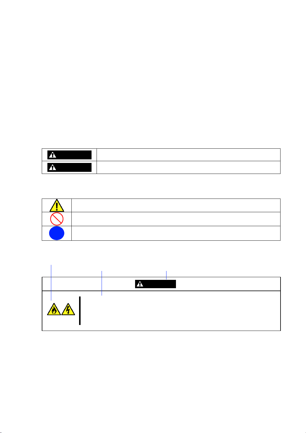
In the User's Guide or warning labels, "WARNING" or "CAUTION" is used to indicate a degree of
danger. These terms are defined as follows:
WARNING
CAUTION
Precautions and notices against hazards are presented with one of the following three symbols. The
individual symbols are defined as follows:
This symbol indicates the presence of a hazard if the instruction is ignored.
An image in the symbol illustrates the hazard type. (Attention)
This symbol indicates prohibited actions. An image in the symbol illustrates a particular
prohibited action. (Prohibited Action)
This symbol indicates mandatory actions. An image in the symbol illustrates a
mandatory action to avoid a particular hazard. (Mandatory Action)
(Example)
(Example)
Symbol to draw attention
Indicates the presence of a hazard that may result in death or serious
personal injury if the instruction is ignored.
Indicates the presence of a hazard that may cause minor personal injury,
including burns, or property damage if the instruction is ignored.
Description of a danger Term indicating a degree of danger
CAUTION
Plug in to a proper power source.
Use a proper wall outlet of the specified voltage. Use of an improper power source
may cause a fire or a power leak.
Page 4
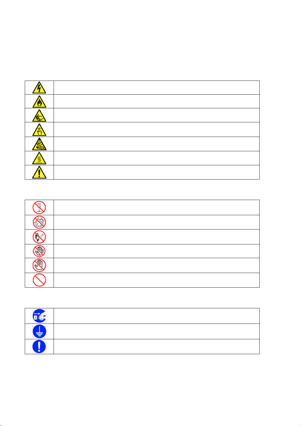
SYMBOLS USED IN THIS MANUAL AND WARNING LABELS
Attentions
Indicates that improper use may cause an electric shock.
Indicates that improper use may cause fumes or fire.
Indicates that improper use may cause fingers to be caught.
Indicates that improper use may cause personal injury.
Indicates that improper use may cause explosion.
Indicates that improper use may cause personal injury due to high temperature.
Indicates a general notice or warning that cannot be specifically identified.
Prohibited Actions
Do not disassemble, repair, or modify the Storage and I/O Blade. Otherwise, an
electric shock or fire may be caused.
Keep away from water or liquid. Otherwise, an electric shock or fire may be caused.
Keep away from fire. Otherwise, an ignition may be caused.
Do not touch the Storage and I/O Blade with wet hand. Otherwise, an electric shock
may be caused.
Do not touch any component other than specified. Otherwise, an electric shock or
personal injury such as burns may be caused.
Indicates a general prohibited action that cannot be specifically identified.
Mandatory Action
Unplug the power cord of the CPU Blade. Otherwise, an electric shock or fire may be
caused.
Be sure to provide earthing. Otherwise, an electric shock or fire may be caused.
Indicates a mandatory action that cannot be specifically identified. Make sure to follow
the instruction.
Page 5
NOTE: This equipment has been tested and found to comply with the limits for a Class A digital
device, pursuant to Part 15 of the FCC Rules. These limits are designed to provide reasonable
protection against harmful interference when the equipment is operated in a commercial
environment. This equipment generates, uses, and can radiate radio frequency energy and, if not
installed and used in accordance with the instruction manual, may cause harmful interference to
radio communications. Operation of this equipment in a residential area is likely to cause harmful
interference in which case the user will be required to correct the interference at his own expense.
Page 6

Trademarks
NEC ESMPRO and NEC EXPRESSBUILDER are trademarks of NEC Corporation.
Microsoft, Windows, Windows Server, Windows NT, and MS-DOS are registered trademarks or trademarks of Microsoft
Corporation in the United States and other countries.
Intel, Intel logo, Xeon, and Xeon Inside are registered trademarks of Intel Corporation in the United States and other
countries.
Datalight is a registered trademark of Datalight, Inc.
ROM-DOS is a trademark of Datalight, Inc.
AT is a registered trademark of International Business Machines Corporation in the United States and other countries.
LSI and the LSI logo design are trademarks or registered trademarks of LSI Corporation.
Adaptec and its logo is a registered trademark of Adaptec, Inc. of United States.
SCSISelect is a trademark of Adaptec, Inc. of the United States.
Adobe, Adobe logo, and Acrobat are trademarks of Adobe Systems Incorporated.
All other product, brand, or trade names used in this publication are the trademarks or registered trademarks of their
respective trademark owners.
Windows Server 2008 stands for Microsoft® Windows Server® 2008 Standard Operating system and Microsoft® Windows
Server® 2008 Enterprise operating system. Windows Vista stands for Microsoft® Windows Vista® Business operating
system. Windows Server 2003 x64 Editions stands for Microsoft® Windows Server® 2003 R2, Standard x64 Edition
Operating system and Microsoft® Windows Server® 2003 R2, Enterprise x64 Edition operating system, or Microsoft
Windows Server® 2003, Standard x64 Edition operating system and Microsoft® Windows Server® 2003, Enterprise x64
Edition operating system. Windows Server 2003 stands for Microsoft® Windows Server® 2003 R2, Standard Edition
operating system and Microsoft® Windows Server® 2003 R2, Enterprise Edition operating system, or Microsoft® Windows
Server® 2003, Standard Edition operating system and Microsoft® Windows Server® 2003, Enterprise Edition operating
system. Windows XP x64 Edition stands for Microsoft® Windows® XP Professional x64 Edition operating system.
Windows XP stands for Microsoft® Windows® XP Home Edition operating system and Microsoft® Windows® XP
Professional operating system. Windows 2000 stands for Microsoft® Windows® 2000 Server operating system and
Microsoft® Windows® 2000 Advanced Server operating system, and Microsoft® Windows® 2000 Professional operating
system. Windows NT stands for Microsoft® Windows NT® Server network operating system version 3.51/4.0 and
Microsoft® Windows NT® Workstation operating system version 3.51/4.0. Windows Me stands for Microsoft® Windows
Millennium Edition operating system. Windows 98 stands for Microsoft® Windows®98 operating system. Windows 95
stands for Microsoft® Windows®95 operating system.
®
®
Momentary voltage drop prevention:
This product may be affected by a momentary voltage drop caused by lightning. To prevent a
momentary voltage drop, an AC uninterruptible power supply (UPS) unit should be used.
Notes:
(1) No part of this manual may be reproduced in any form without the prior written permission of
NEC Corporation.
(2) The contents of this User's Guide may be revised without prior notice.
(3) The contents of this User's Guide shall not be copied or altered without the prior written
permission of NEC Corporation.
(4) All efforts have been made to ensure the accuracy of all information in this User's Guide. If
you notice any part unclear, incorrect, or omitted in this User's Guide, contact the service
representative where you purchased this product.
(5) NEC assumes no liability arising from the use of this product, nor any liability for incidental or
consequential damages arising from the use of this User's Guide regardless of Item (4).
Page 7

PREFACE
Welcome to the Storage and I/O Blade for NEC Express5800/SIGMABLADE.
Connecting the Storage and I/O Blade with the CPU blade can expand I/O capabilities with up to six
hard disk drives and two mezzanine cards.
Read this User's Guide thoroughly to fully understand handling of the Storage and I/O Blade and
appreciate its functions to the maximum extent.
i
Page 8

ii
ABOUT THIS USER'S GUIDE
This User's Guide is a guide for proper setup and use of the Storage and I/O Blade.
This User's Guide also covers useful procedures for dealing with difficulties and problems that may
arise during setup or operation of the Storage and I/O Blade.
Keep this manual for future use.
The following describes how to proceed with this User's Guide.
How to Use This User's Guide
To aid you in finding information quickly, this User's Guide contains the following information:
Chapter 1 Notes on Using Your Storage and I/O Blade
includes information that needs attention to use the CPU blade and Storage and I/O Blade.
Make sure to read this chapter before setting up and using the CPU blade and Storage and
I/O Blade. It also includes requirements and advisory information for transfer and disposal of
the Storage and I/O Blade.
Chapter 2 General Description
includes information necessary to use the Storage and I/O Blade, such as names and
functions of its components.
Chapter 3 Setting Up Your Storage and I/O Blade
tells you how to check MAC address, and procedure to install the Storage and I/O Blade in
Blade Enclosure.
Chapter 4 Configuring Your Storage and I/O Blade
tells you how to configure the RAID system with the hard disk drives in Storage and I/O
Blade.
Chapter 5 Installing the Operating System
describes how to install the device drivers for the Storage and I/O Blade.
Chapter 6 Installing and Using Utilities
Refer to the User's Guide of the CPU Blade contained in the NEC EXPRESSBUILDER DVD
Chapter 7 Maintenance
provides you with all the information necessary to maintain successful operation of the
Storage and I/O Blade.
Chapter 8 Troubleshooting
contains helpful information for solving problems that might occur with your system.
Chapter 9 Upgrading Your Storage and I/O Blade
provides you with instructions for upgrading your system with optional mezzanine cards, and
hard disk drives.
Appendix A Specification
provides specifications for your Storage and I/O Blade.
Page 9

Text Conventions
The following conventions are used throughout this User's Guide. For safety symbols, see
"SAFETY INDICATIONS" provided earlier.
iii
IMPORTANT:
NOTE:
Items that are mandatory or require attention when using the
Storage and I/O Blade
Helpful and convenient piece of information
IN THE PACKAGE
The carton contains various accessories, as well as the Storage and I/O Blade itself. See the packing
list to make sure that you have everything and that individual components are not damaged. If you
find any component missing or damaged, contact your service representative.
Store the provided accessories in a designated place for your convenience. You will need
them to install an optional device or troubleshoot the Storage and I/O Blade, as well as to
set it up.
Make a backup copy of each provided floppy disk, if any. Store the original disk as the
master disk in a designated place, and use its copy.
Improper use of any provided floppy disk or CD-ROM may alter your system
environment. If you find anything unclear, immediately ask your service representative for
help.
Page 10

iv
CONTENTS
SAFETY INDICATIONS .............................................................................................................. iii
Symbols Used in This Manual and Warning Labels .......................................................................iv
Preface ..............................................................................................................................................i
About This User's Guide..................................................................................................................ii
In the Package................................................................................................................................ iii
Chapter 1 Notes on Using Your Storage and I/O Blade.............................................. 1-1
Warning Labels ............................................................................................................................ 1-1
Safety Notes................................................................................................................................. 1-2
For Proper Operation ................................................................................................................... 1-5
Transfer to Third Party................................................................................................................. 1-7
Disposal and Consumables .......................................................................................................... 1-8
User Support ................................................................................................................................ 1-9
Chapter 2 General Description ..................................................................................... 2-1
Overview...................................................................................................................................... 2-2
Standard Features......................................................................................................................... 2-3
Names and Functions of Components ......................................................................................... 2-4
Front View ............................................................................................................................... 2-4
Internal View ........................................................................................................................... 2-5
External View .......................................................................................................................... 2-6
Hard Disk Drive ...................................................................................................................... 2-7
Lamp Indications..................................................................................................................... 2-8
Using Your Storage and I/O Blade..............................................................................................2-11
Power-on of Storage and I/O Blade........................................................................................2-11
Power-off of Storage and I/O Blade .......................................................................................2-11
Device Identification ............................................................................................................. 2-12
Chapter 3 Setting Up Your Storage and I/O Blade ...................................................... 3-1
Before Installing Storage and I/O Blade ...................................................................................... 3-2
Check of MAC Address........................................................................................................... 3-2
Installing the Storage and I/O Blade............................................................................................3-3
Installation Order..................................................................................................................... 3-3
Installing in Blade Enclosure...................................................................................................3-5
Installing the Hard Disk Drive................................................................................................... 3-10
Page 11

Chapter 4 Configuring Your Storage and I/O Blade ................................................... 4-1
RAID System Configuration ........................................................................................................4-2
RAID........................................................................................................................................4-2
Configuration by Internal RAID Controller.............................................................................4-8
Before Using WebBIOS .........................................................................................................4-14
Using WebBIOS.....................................................................................................................4-17
Configuring Virtual Drive ......................................................................................................4-33
Operation of Various Features ................................................................................................4-49
Locate.....................................................................................................................................4-60
Slow Initialize ........................................................................................................................4-61
WebBIOS and Universal RAID Utility ..................................................................................4-62
Chapter 5 Installing the Operating System ................................................................. 5-1
Installing and Setting Device Drivers...........................................................................................5-2
Installing Internal RAID Controller Driver..............................................................................5-2
PROSet.....................................................................................................................................5-2
Network Driver ........................................................................................................................5-3
Optional Network Board Driver...............................................................................................5-3
Setup of Adapter Fault Tolerance (AFT)/Adaptive Load Balancing (ALB) ............................5-3
Setting WOL ............................................................................................................................5-3
Setting Receive Side Scaling....................................................................................................5-4
Setting up Scalable Networking Pack (SNP) ...........................................................................5-5
Installing Fibre Channel Controller Driver (N8403-018).........................................................5-6
Setting for Solving Problems........................................................................................................5-7
Network Monitor......................................................................................................................5-7
Updating the System...................................................................................................................5-10
Making Backup Copies of System Information..........................................................................5-10
v
Chapter 6 Installing and Using Utilities ....................................................................... 6-1
Chapter 7 Maintenance.................................................................................................. 7-1
Making Backup Copies ................................................................................................................7-1
System Diagnostics.......................................................................................................................7-2
Test Items.................................................................................................................................7-2
Startup and Exit of System Diagnostics ...................................................................................7-2
Relocating/Storing the Unit ..........................................................................................................7-3
Page 12

vi
Chapter 8 Troubleshooting ........................................................................................... 8-1
System Viewers............................................................................................................................ 8-2
Error Messages ............................................................................................................................ 8-3
POST Error Messages .............................................................................................................8-3
Messages displayed by RAID Controller during POST .......................................................... 8-3
Lamps ...................................................................................................................................... 8-6
Error Messages on Virtual LCD .............................................................................................. 8-6
Solving Problems......................................................................................................................... 8-9
Storage and I/O Blade.............................................................................................................. 8-9
Problems with Windows........................................................................................................ 8-13
Problems with RAID System and RAID Controller.............................................................. 8-19
Problems with N8403-018 FibreChannel Controller............................................................. 8-22
Collecting Event Log ................................................................................................................. 8-22
Maintenance Tools ..................................................................................................................... 8-22
Function of Maintenance Tools ............................................................................................. 8-22
Chapter 9 Upgrading Your Storage and I/O Blade ...................................................... 9-1
Safety Notes................................................................................................................................. 9-2
Anti-static Measures .................................................................................................................... 9-3
Confirmation after Installation/Removal ..................................................................................... 9-4
Preparation for Installation .......................................................................................................... 9-5
Installation/Removal Procedure................................................................................................... 9-6
Mezzanine Card....................................................................................................................... 9-6
Hard Disk Drive .....................................................................................................................9-11
Appendix A Specifications ........................................................................................... A-1
Page 13
Chapter 1
Notes on Using Your Storage and I/O Blade
This chapter includes information necessary for proper and safe operation of the Storage and I/O
Blade.
WARNING LABELS
The warning label is attached to components with possible danger or their vicinity in your blade to
inform the user that a hazardous situation may arise when operating the blade. (Do not intentionally
remove or damage any of the labels.)
If you find any labels totally/partially removed or illegible due to damage, contact your service
representative.
Page 14
1-2 Notes on Using Your Storage and I/O Blade
SAFETY NOTES
This section provides notes on using the Storage and I/O Blade safely. Read this section carefully to
ensure proper and safe use of the Storage and I/O Blade. For symbols, see "SAFETY
INDICATIONS" provided earlier.
For part names described in the safety instruction chapter in this guide, refer to "Features and
Controls" in Chapter 2.
WARNING
Do not use the Storage and I/O Blade for services where critical high
availability may directly affect human lives.
The Storage and I/O Blade is not intended to be used with or control facilities
or devices concerning human lives, including medical devices, nuclear
facilities and devices, aeronautics and space devices, transportation facilities
and devices; and facilities and devices requiring high reliability. NEC
assumes no liability for any accident resulting in personal injury, death, or
property damage if the Storage and I/O Blade has been used in the above
conditions.
Do not disassemble, repair, or alter the Storage and I/O Blade.
Never attempt to disassemble, repair, or alter the Storage and I/O Blade on
any occasion other than described in this User's Guide. Failure to follow this
instruction may cause an electric shock or fire as well as malfunctions of the
Storage and I/O Blade.
Do not remove the battery.
Your Storage and I/O Blade contains the lithium and Li-Ion batteries. Do not
remove the battery. Danger of explosion if the battery is incorrectly replaced.
Placing the battery close to a fire or in the water may cause an explosion.
When the Storage and I/O Blade does not operate appropriately due to the
dead batteries, contact your service representative to replace the battery. Do
not disassemble the Storage and I/O Blade to replace or recharge the battery
by yourself.
Do not use the Storage and I/O Blade if any smoke, odor, or noise is present.
If smoke, odor, or noise is present, immediately turn off the system and
disconnect the power plug from the outlet, then contact your service
representative. Using the Storage and I/O Blade in such conditions may
cause a fire.
Keep needles or metal objects away from the Storage and I/O Blade .
Do not insert needles or metal objects into ventilation holes in the Storage
and I/O Blade . Doing so may cause an electric shock.
Use the devices only in the specified areas.
CPU blades and Storage and I/O Blade should be installed in the dedicated
Blade Enclosure for their uses. Do not install the CPU blades and Storage
and I/O Blade in a chassis other than the Blade Enclosure. Failure to follow it
may result in fire and/or electric shock to occur.
Page 15
Notes on Using Your Storage and I/O Blade 1-3
WARNING
Do not use the equipment in the place where corrosive gases exist.
Make sure not to locate or use the CPU blade and Storage and I/O Blade in
the place where corrosive gases (sulfur dioxide, hydrogen sulfide, nitrogen
dioxide, chlorine, ammonia, ozone, etc) exist.
Also, do not set it in the environment where the air (or dust) includes
components accelerating corrosion (ex. sulfur, sodium chloride) or conductive
metals. There is a risk of a fire due to corrosion and shorts of an internal
printed board.
Do not handle the CPU blade or Storage and I/O Blade while it is installed in
the Blade Enclosure.
To install or remove an option from the CPU blade or Storage and I/O Blade,
first turn off the power of the CPU blade and remove the CPU blade and
Storage and I/O Blade from the Blade Enclosure. If you touch parts on the
CPU blade or Storage and I/O Blade with it connected to the Blade Enclosure,
you may get an electric shock.
Do not install or remove more than one Storage and I/O Blade at a time.
Install or remove Storage and I/O Blade one by one. If you install or remove
more than one Storage and I/O Blades at a time or a Storage and I/O Blade
with the cover of another slot removed, you may be electrically shocked.
CAUTION
Keep water or foreign matter away from the CPU blade and Storage and I/O
Blade.
Do not let any form of liquid (water etc.) or foreign matter (e.g., pins or paper
clips) enter the CPU blade and Storage and I/O Blade. Failure to follow this
warning may cause an electric shock, a fire, or a failure of the CPU blade and
Storage and I/O Blade. When such things accidentally enter the CPU blade
and Storage and I/O Blade, immediately turn off the power and disconnect the
power plug from the outlet. Do not disassemble the CPU blade and Storage
and I/O Blade. Contact your service representative.
Make sure to complete device installation.
Always install a CPU blade, Storage and I/O Blade, hard disk drive, and
option board firmly. An incompletely installed device may cause a contact
failure, resulting in smoking or fire.
Do not use any unauthorized interface cable.
Use only interface cables provided by NEC and locate a proper device and
connector before connecting a cable. Using an authorized cable or
connecting a cable to an improper destination may cause a short circuit,
resulting in a fire.
Also, observe the following notes on using and connecting an interface cable.
Do not use any damaged cable connector.
Do not step on the cable.
Do not place any object on the cable.
Do not use the Blade Enclosure with loose cable connections.
Do not use any damaged cable.
Page 16
1-4 Notes on Using Your Storage and I/O Blade
Avoid installation in extreme temperature conditions.
Immediately after the Storage and I/O Blade is powered off, its internal
components and components in Blade Enclosure are very hot. Leave them
until their internal components fully cool down before installing/removing any
component.
Avoid contact with the CPU blade and Storage and I/O Blade during
thunderstorms.
Disconnect the power plug from the outlet when a thunderstorm is
approaching. If it starts thundering before you disconnect the power plug, do
not touch any part of the CPU blade and Storage and I/O Blade including the
cables. Failure to follow this warning may cause a fire or an electric shock.
Keep animals away from the CPU blade and Storage and I/O Blade.
Pet's discharges or fur may enter the CPU blade and Storage and I/O Blade
and cause a fire or electric shock.
Do not use a cellular phone or pager around the CPU blade and Storage and
I/O Blade.
Turn off the cellular phone or pager. Radio interference may cause
malfunctions of the CPU blade and Storage and I/O Blade.
CAUTION
Page 17

Notes on Using Your Storage and I/O Blade 1-5
FOR PROPER OPERATION
Observe the following notes for successful operation of the Storage and I/O Blade. Use of the
Storage and I/O Blade ignoring the notes will cause malfunctions or failures of the Storage and I/O
Blade .
Storage and I/O Blade
– The Storage and I/O Blade must be installed in the Blade Enclosure (SIGMABLADE).
– Install or remove Storage and I/O Blades one by one.
– Hold the portions covered with metal plates when a Storage and I/O Blade is installed
or removed. To carry a Storage and I/O Blade, put it into the case in which the Storage
and I/O Blade was contained at the purchase and pack it into the package.
– The Storage and I/O Blade is extremely sensitive to static electricity. Make sure to
touch the metal frame of the chassis to discharge static electricity from your body
before handling the Storage and I/O Blade. Do not touch the Storage and I/O Blade
terminals or onboard parts by a bare hand and place the Storage and I/O Blade directly
on the desk.
– Store the unit under the storage condition (temperature: –10 to 55°C, humidity: 20 to
80%, without condensation) to allow built-in devices and the unit to operate correctly
in the next operation.
– The power of the Storage and I/O Blade is controlled by the CPU blade connected.
– The Storage and I/O Blade contains precision component that is easily affected by
drastic temperature change. If the Storage and I/O Blade is used after storage or
relocation, make sure that the Storage and I/O Blade is fully adapted to the operating
environment.
– Turn on the power of each CPU blade by the use of the POWER switch or the remote
power-on after the period of 30 seconds or longer has passed from the supply of AC
power (the POWER lamp of the CPU blade goes on amber) to every power unit. The
power of the CPU blade may not be turned on if the power-on operation is done within
the period of less than 30 seconds from the supply of AC power. After making sure that
the AC power is supplied to every power unit, turn on the power of each CPU blade by
using the POWER switch.
– Remove the Storage and I/O Blade after making sure that the CPU blade has been
powered off.
Page 18

1-6 Notes on Using Your Storage and I/O Blade
Optional hard disk drive, mezzanine card, and other electronic components
– These components are extremely sensitive to static electricity. Make sure to touch the
metal frame of the chassis to discharge static electricity from your body before
handling the components. Do not touch the terminals or parts on the components by a
bare hand and place the components directly on the desk.
– Make sure that the options are optional devices for the purchased Storage and I/O
Blade. If an option can be installed or connected to the Storage and I/O Blade, the
option may not operate properly and further the Storage and I/O Blade itself may be
defected.
– The internal option device contains precision component that is easily affected by
drastic temperature change. If the device is used after storage or relocation, make sure
that the device is fully adapted to the operating environment.
Do not use a cellular phone or pager around the Storage and I/O Blade.
Turn off the cellular phone or pager. Radio interference may cause malfunctions of the
Storage and I/O Blade.
Page 19

Notes on Using Your Storage and I/O Blade 1-7
TRANSFER TO THIRD PARTY
The following must be observed when you transfer (or sell) the Storage and I/O Blade or software
provided with the Storage and I/O Blade to a third party:
Storage and I/O Blade
Make sure to provide this manual along with the Storage and I/O Blade to a third party.
IMPORTANT: About data on the hard disk drive
Be sure to take appropriate measures not to leak important data (e.g.,
customers' information or companies' management information) on the
removed hard disk drive to any third parties.
Data seems to be erased when you empty "Recycle Bin" of Windows or
execute the "format" command of the operating system. However, the
actual data remains written on the hard disk drive. Data not erased
completely may be restored by special software and used for
unexpected purposes.
It is strongly recommended that the software or service (both available
at stores) for data erasure should be used in order to avoid the trouble
explained above. For details on data erasure, ask your sales
representative.
Provided Software
To transfer or sell any software application that comes with the Storage and I/O Blade to a third
party, the following requirements must be satisfied:
All provided software applications must be transferred and no backup copies must be
retained.
Transfer requirements listed in "Software License Agreement" that comes with each
software application must be satisfied.
Software applications that are not approved for transfer must be uninstalled before
transferring the Storage and I/O Blade.
Page 20
1-8 Notes on Using Your Storage and I/O Blade
DISPOSAL AND CONSUMABLES
Dispose of the CPU Blade, Storage and I/O Blade, hard disk drives, Blade Enclosure,
option board, floppy disks, and DVD/CD-ROMs according to all national laws and
regulations.
IMPORTANT:
For disposal (or replacement) of the battery on the mother board of
the Storage and I/O Blade, consult with your service representative.
It is the user's responsibility to completely erase or modify all the
data stored in storage device such as hard disk drive so that the data
cannot be restored.
The Storage and I/O Blade contains some components that are only good for a limited
period of time and require replacement (e.g., lithium or Li-Ion battery). For stable
operation of the Storage and I/O Blade, NEC recommends you replace these components
on a regular basis. Consult with your service representative for replacement or the product
lives.
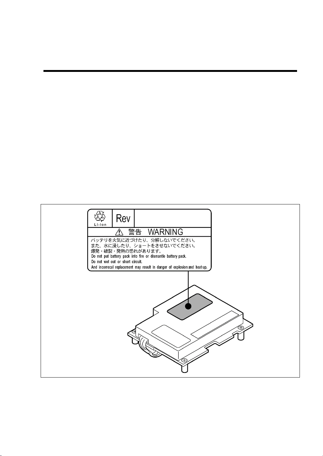
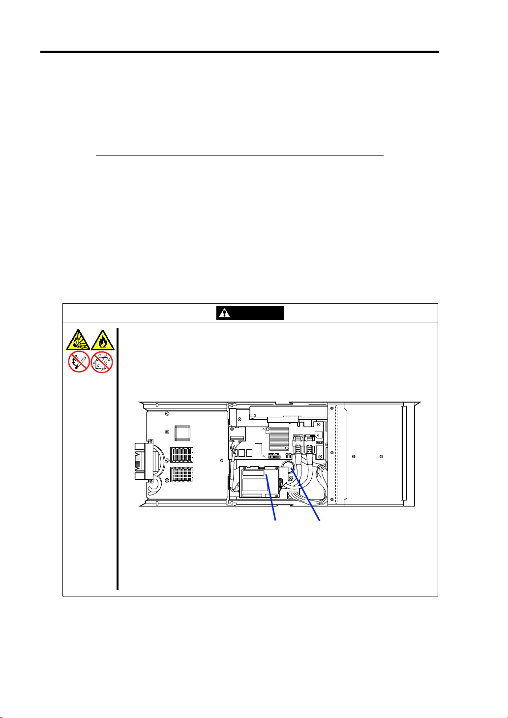
WARNING
Do not remove the battery.
The Storage and I/O Blade contains the lithium and Li-Ion batteries. Do not
remove the battery. Placing the battery close to a fire or in the water may cause
an explosion.
For the location of battery on the option board, refer to the manual that comes
with the option board.
Li-Ion battery
(Battery pack)
Lithium battery
Storage and I/O Blade
Page 21

Notes on Using Your Storage and I/O Blade 1-9
USER SUPPORT
Before Asking for Repair, do the following when the Storage and I/O Blade appears to fail:
1. Check if the power cord and the cables to other devices are properly connected.
2. See Chapter 8 to find if your problem fits the description. If it does, take the
recommended measure for it.
3. Check if the software required for operation of the Storage and I/O Blade is properly
installed.
If the Storage and I/O Blade still appears to fail after you have taken the above actions, consult with
your service representative immediately. Take notes on lamp indications of the Storage and I/O
Blade and alarm indications on the display unit before consultation, which may provide a significant
help to your service representative.
Page 22
1-10 Notes on Using Your Storage and I/O Blade
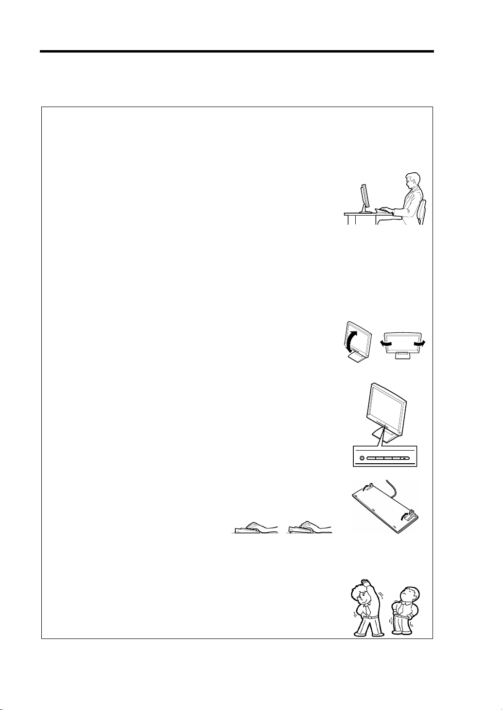
Advice for Health
The longer you keep using the computer equipment, the more you become
tired, which may cause disorders of your body. When you use a computer,
observe the following to keep yourself from getting tired:
Good Working Posture
You have good posture if the following are satisfied when you use a
computer:
• You sit on a chair with your back straight.
• Your hands are parallel with the floor when you put them on the
keyboard.
• You look at the screen slightly lower than your eye height.
You have "good working posture" as described in the above when no part
of your body is under excess strain, in other words when your muscles are
most relaxed.
You have "bad posture" when you sit with your back hunched up or you
operate a display unit with your face close to the screen. Bad working
posture may cause eye strain or poor eyesight.
Adjustment of Display Unit Angles
Most display units are designed for adjustment of the horizontal and
vertical angles. This adjustment is important to prevent the screen from
reflecting bright lights and to make the display contents easy to see. You
will not be able to keep "good working posture" and you will feel more tired
than you should if you operate a display unit without adjusting horizontal
and vertical angles.
Adjustment of Screen Brightness and Contrast
The display unit has brightness and contrast adjustment functions. The
most suitable brightness and contrast depend on the individual and the
working environment (well-lighted room or insufficient light). Adjust
brightness and contrast so that the screen will be easy to see. An
extremely bright or dark screen will give a bad effect to your eyes.
Adjustment of Keyboard Angle
The keyboard provided with the CPU Blade is designed for adjustment of
an angle. Adjust the keyboard angle at which the keyboard is easy to
operate. The adjustment assists in reducing strain on your shoulders,
arms, and fingers.
Cleaning of Equipment
Clean equipment regularly. It is difficult to see the display contents on a
dusty screen. Keeping equipment clean is also important for your sight.
Fatigue and Rest
If you feel tired, you should stop working and do light exercises.
Page 23

Chapter 2
General Description
This chapter provides information that you should be familiar with before using the Storage and I/O
Blade. It includes names and functions of the components and features of the Storage and I/O Blade.
Page 24
2-2 General Description
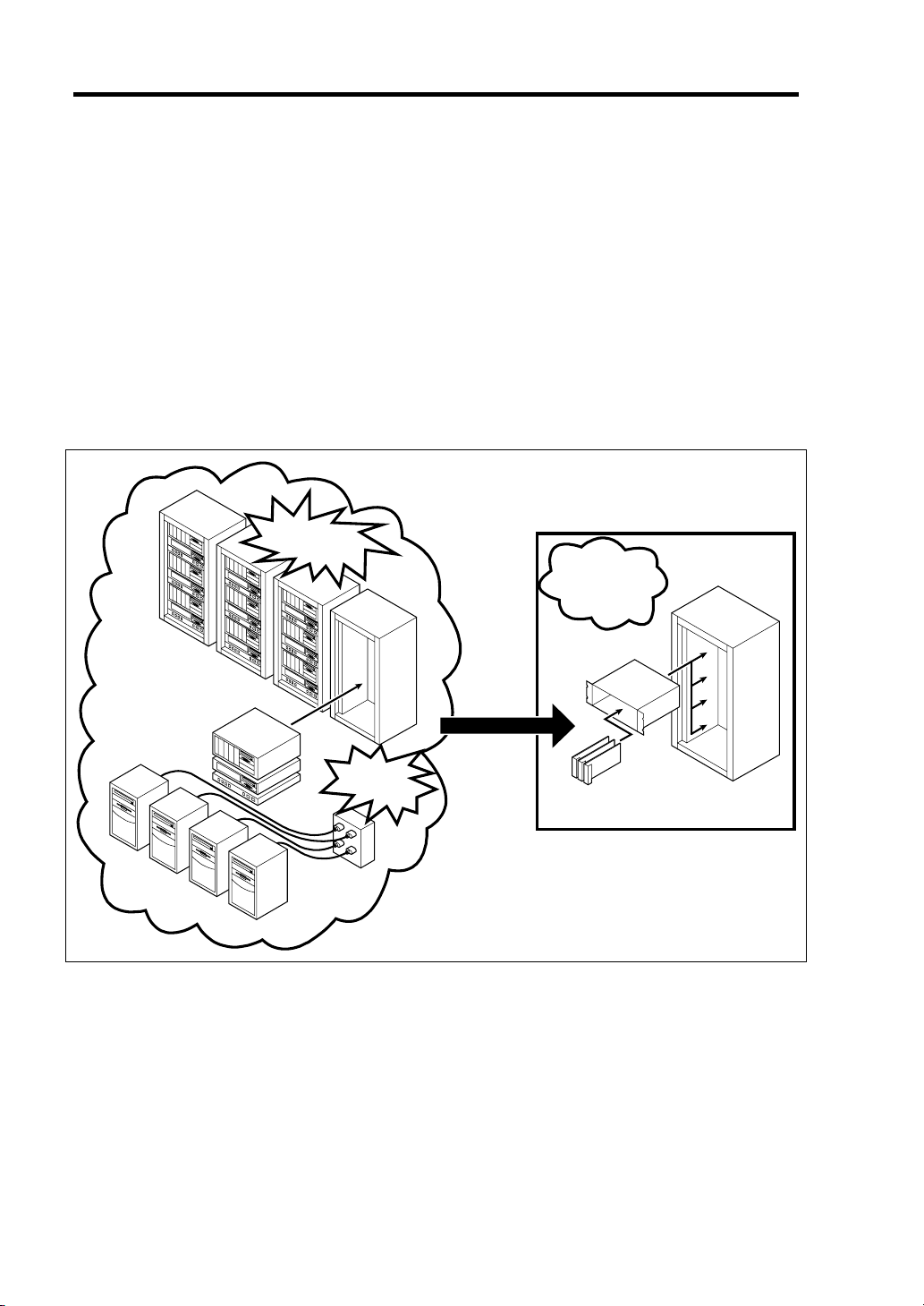
OVERVIEW
NEC Express5800/SIGMABLADE is a modular and multiprocessing system that includes processor,
memory, network connections, optional add-in card slot, and associated electronics, all on a single
mother board called a CPU blade.
The CPU blade, hard disk drive, and other CPU blades are typically installed into a rack-mountable
enclosure that houses multiple CPU blades that share common resources such as cabling, power
supplies, and cooling fans.
This high-density technology reduces the installation space, lowers a total cost of ownership, and
offers increased computing density while ensuring both maximum scalability and ease of
management.
Increase
in installation space
Save space
and
save power
Blade Enclosure
Increase in
power
consumption
CPU blade or
Storage and I/O Blade
The Storage and I/O Blade and hard disk drives contained in the Storage and I/O Blade do not
require any power cord and cables to connect with the CPU blade. In addition, the Storage and I/O
Blade can contain optional mezzanine cards for blade.
Page 25
STANDARD FEATURES
High performance
High-speed 1000BASE-T interface x2
(1Gbps supported)
High-speed disk access (SAS)
High-reliability
Temperature detection
Error notification
Internal voltage monitoring feature
BIOS password feature
Auto-rebuild feature (hot-swappable)
Expandability Management Utilities
Equipped with option slot that makes up
to two additional slot option cards
available.
Two network ports
Up to six hard disk drives (SAS 2.5-inch)
can be connected
NEC ESMPRO
Universal RAID Utility
Monitoring of system status through EM
card
General Description 2-3
Maintenance Features Easy to use
Off-line Maintenance Utility
Configuration on Disk feature
Cable-less SAS HDD
Page 26
2-4 General Description
NAMES AND FUNCTIONS OF COMPONENTS
This section describes the names and features of the components in the device.
Front View
1
0 1 2
12
2
3
1
ID
6
5
4
3 4 5
7
1 Hard disk drive
Upper: Slots 0, 1, and 2 from left to right
Lower: Slots 3, 4, and 5 from left to right
2 POWER lamp
The lamp goes on green when the Storage and I/O Blade is powered on.
The lamp goes on amber when the Storage and I/O Blade is powered off but the power is
supplied from the power supply unit.
3 STATUS lamp (green/amber/red)
The lamp indicates the status of the Storage and I/O Blade. See "Lamp Indications" described
later for the indications and meanings of the lamp.
4 LAN1 Link/Access lamp (green)
The lamp lights when LAN port 1 is connected to the network.
The lamp flashes when data is being transmitted.
5 LAN2 Link/Access lamp (green)
The lamp lights when LAN port 2 is connected to the network.
The lamp flashes when data is being transmitted.
6 ID lamp (blue)
The lamp is intended to identify the Storage and I/O Blade in the system. The lamp is lit by a
software command.
7 Eject lever
Pull the lever to remove the Storage and I/O Blade from the Blade Enclosure.
Page 27
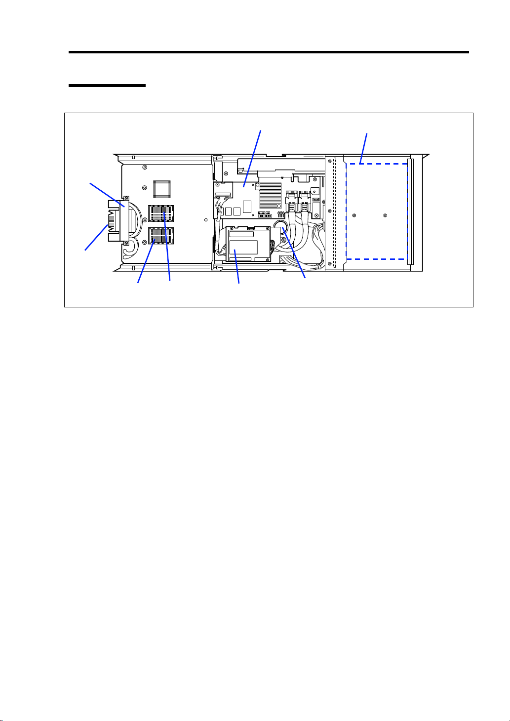
Internal View
8
7
General Description 2-5
12
65 4
1 Hard disk drive slot
2 RAID controller
3 Lithium battery
4 Battery for RAID controller
5 Type I mezzanine slot
Slot to install mezzanine card for blade
6 Type II mezzanine slot
Slot to install mezzanine card for blade
7 MP connector
Used to connect with the midplane in Blade Enclosure.
8 MAC address label
3
Page 28
2-6 General Description
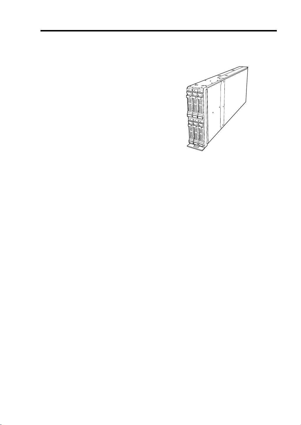
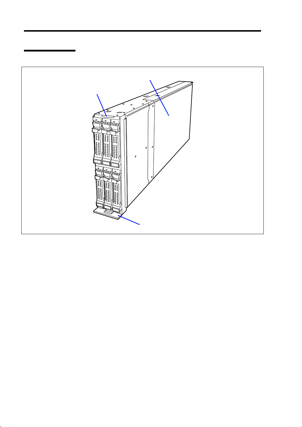
External View
1
2
1 Top cover
2 Slide tag
3 Eject lever
3
Page 29
General Description 2-7
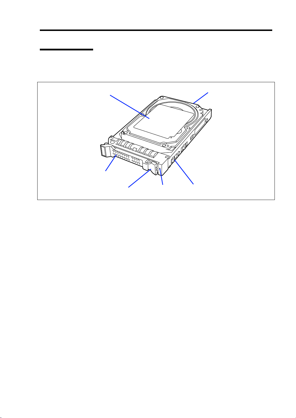
Hard Disk Drive
The hard disk drive is an optional device. Hard disk drive is sensitive to static electricity, vibration,
and shock. Handle it carefully.
12
6
345
1 Hard disk drive
2 BP connector
Used to connect with the HDD backplane in Storage and I/O Blade.
3 Drive carrier
4 Disk access lamp (green/amber)
Lights green in accessing to a hard disk drive.
Lights amber if a fault occurs in a hard disk drive. Blinks green or amber alternately or blinks
amber while array disks are rebuilt.
5 Lever
The lever is intended to unlock the hard disk drive. Pull the lever to remove the hard disk drive.
6 Handle
Hold the handle when the hard disk drive is installed or removed.
Page 30
2-8 General Description
Lamp Indications
This section describes the positions and display meanings of the lamps on the Storage and I/O Blade
and other devices.
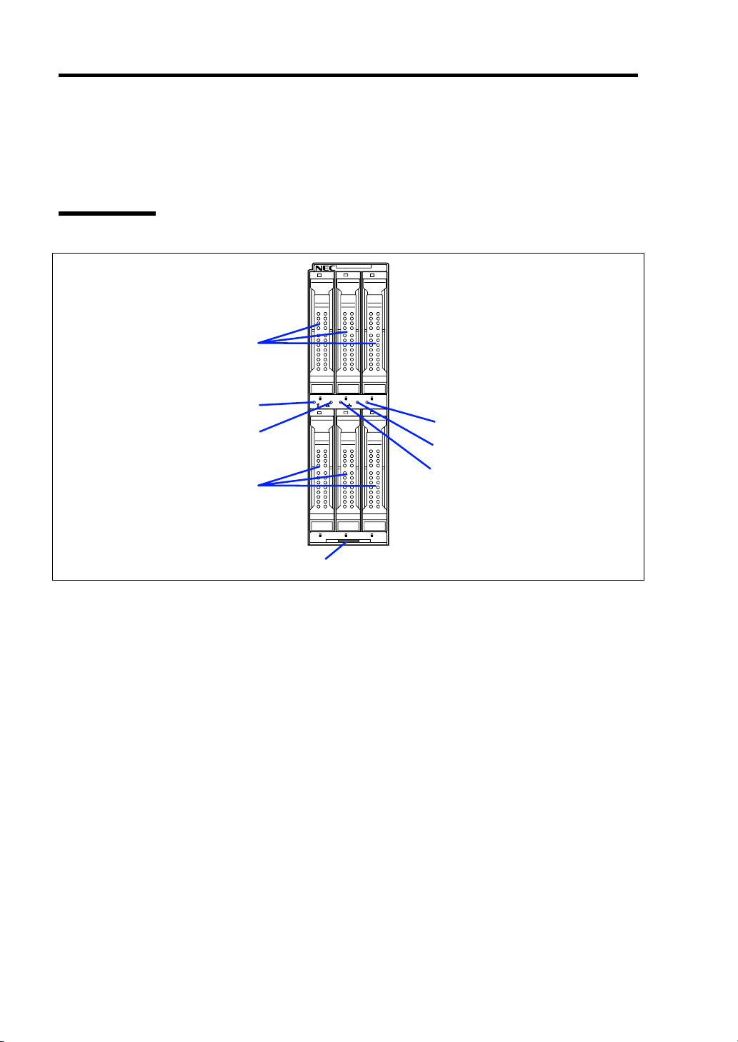
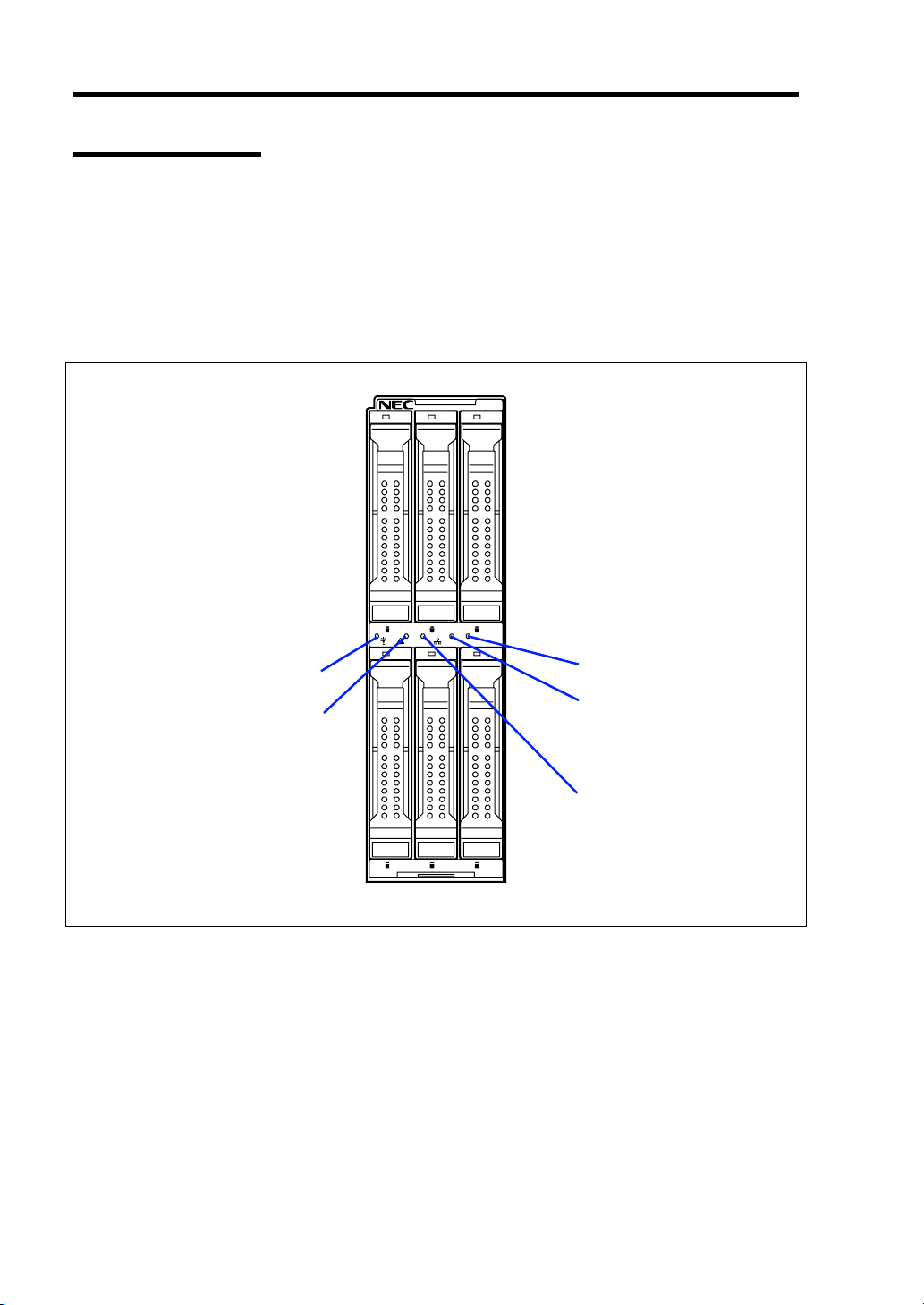
Storage and I/O Blade
The Storage and I/O Blade includes five lamps.
0 1 2
POWER lamp
STATUS lamp
3 4 5
12
ID
ID lamp
LAN2 Link/Access
lamp
LAN1 Link/Access
lamp
POWER Lamp
The POWER lamp lights green while the power of the Storage and I/O Blade is on. The lamp lights
amber when the Storage and I/O Blade is powered off but the power is supplied from the power
supply unit in Blade Enclosure. The lamp is off if the power is not supplied to the Storage and I/O
Blade.
Page 31

General Description 2-9
STATUS Lamp
The STATUS lamp stays lit in green when the Storage and I/O Blade is in successful operation.
When the STATUS lamp is flashing in amber or red, it indicates that the system has failed.
In addition, you can view the detailed information on error message on virtual LCD when the
STATUS lamp is flashing in amber or red. You can use the virtual LCD through the Web console of
Blade Enclosure. See Chapter 8 for indication on virtual LCD, descriptions, and actions to take. If
an error occurs, contact your service representative.
The following tables list indications of the STATUS lamp, descriptions, and actions to take.
NOTE: The Storage and I/O Blade does not support EXPRESSSCOPE
Engine (BMC). You cannot view the error log through NEC ESMPRO
Manager.
STATUS lamp indications
STATUS lamp
Status Color
On Green The Storage and I/O Blade
Off –
On Red BMC is being initialized.
Flash Red See the table "Virtual LCD indications when STATUS lamp is flashing in
Flash Amber See the table "Virtual LCD indications when STATUS lamp is flashing in
Description Action
–
is operating normally.
The power is turned off.
red" described in Chapter 8.
amber" described in Chapter 8.
Turn on the power.
1. Wait until the lamp goes off.
2. If the lamp still goes on, check
installation of the Storage and I/O
Blade.
NOTE: If the Storage and I/O Blade is powered off while the STATUS
lamp is flashing in amber or red, the indication of the STATUS lamp is
retained except for certain factors. When the Storage and I/O Blade is
powered on, the STATUS lamp goes on green (normal status).
Page 32

2-10 General Description
LAN (1 - 2) Link/Access Lamps
The lamp flashes when data is being transmitted through each LAN port. When the power is
supplied to the Storage and I/O Blade from the Blade Enclosure and the link is established, the
Link/Access lamp on the relevant port lights.
The connection of LAN port is physically controlled by the EM card and the switch module
installed in the Blade Enclosure (SIGMABLADE).
To check connection status of LAN port, refer to the User's Guide of the EM card and the switch
module installed in the Blade Enclosure.
ID Lamp
The ID lamp is intended to identify a specific Storage and I/O Blade in the system in which several
blades are installed. Making this lamp being lit can help the maintenance work to identify the faulty
device.
When the detect command is received from management software such as NEC ESMPRO Manager
and Web console of Blade Enclosure, the lamp lights.
DISK ACCESS Lamp
A hard disk drive has one lamp.
DISK ACCESS lamp
The lamp lights green while the hard disk drive is being accessed.
The lamp lights amber if a hard disk drive cannot be interfaced with the Storage and I/O Blade
correctly due to a hardware fault in the Storage and I/O Blade or another failure.
In the disk array configuration, the lamp flashes green and amber alternately while the array disks
are rebuilt (this does not indicate an error). After the rebuilding completes, the lamp returns to the
normal indication. If the rebuilding fails, the lamp is lit amber.
Page 33

General Description 2-11
USING YOUR STORAGE AND I/O BLADE
This section describes the basic operation of the Storage and I/O Blade.
The power of the Storage and I/O Blade is automatically controlled in linkage with the power of
CPU blade. Refer to the manual that comes with your CPU blade for power on/off of the Storage
and I/O Blade.
Power-on of Storage and I/O Blade
The power of the Storage and I/O Blade is automatically controlled in linkage with the power of the
connected CPU blade. Refer to the manual that comes with your CPU blade to power on the Storage
and I/O Blade.
IMPORTANT: Perform the power-on operation of the CPU blade by
either the use of the POWER switch or the remote power-on after the
period of 30 seconds or longer has passed from the supply of AC power
to CPU blade and Storage and I/O Blade. The POWER lamps on CPU
blade and Storage and I/O Blade goes on amber if they are powered on.
The power-on operation within the period of 30 seconds from the
supply of AC power to them may not turn on the power of the CPU
blade. If so, turn on the power of the CPU blade by using the POWER
switch after making sure that the AC power is supplied to CPU blade
and Storage and I/O Blade.
NOTE: If a power cord on the Blade Enclosure is connected to a
power controller including an uninterruptible power supply (UPS),
make sure that the power of the power controller is turned on.
Power-off of Storage and I/O Blade
The power of the Storage and I/O Blade is automatically controlled in linkage with the power of the
connected CPU blade. Refer to the manual that comes with your CPU blade to power off the
Storage and I/O Blade.
Page 34

2-12 General Description
Device Identification
To identify the device to be maintained among more than one device, ID lamp is used.
The ID lamp is located on the blade device installed in the Blade Enclosure.
The ID lamp allows you to identify the device subject to maintenance among several devices
installed in the Blade Enclosure.
The ID lamp on Storage and I/O Blade can also be made lit blue by proper software commands (e.g.,
NEC ESMPRO Manager or Web console of Blade Enclosure) from the management PC on the
network.
0 1 2
12
3 4 5
ID
ID lamp
Page 35

Chapter 3
Setting Up Your Storage and I/O Blade
This chapter describes how to set up the Storage and I/O Blade appropriate for your system, on a
step-by-step basis.
Page 36

3-2 Setting Up Your Storage and I/O Blade
BEFORE INSTALLING STORAGE AND I/O BLADE
Be sure to check the MAC addresses before installing a Storage and I/O Blade in the Blade
Enclosure.
Check of MAC Address
A MAC address indicates the address specific for the network. It is expressed by 12-digit
alphanumeric. Each of the Storage and I/O Blade has two MAC addresses. Check the MAC
addresses before installing the Storage and I/O Blade in the Blade Enclosure.
A MAC address is indicated in the area as shown in the figure below.
Label indicating MAC address
The address of LAN port depends on the numeral and alphabet of the last digit of MAC address.
When the numeral/alphabet of the last digit is even number, A, C, or E:
The MAC address for LAN port 1 is as described on the label.
The MAC address for LAN port 2 can be obtained by adding 1 to the described MAC
address.
When the numeral/alphabet of the last digit is odd number, B, D, or F:
The MAC address for LAN port 1 can be obtained by adding 1 to the described MAC
address.
The MAC address for LAN port 2 can be obtained by adding 2 to the described MAC
address.
The MAC addresses can be checked from the proper Windows or Linux command.
Windows
Enter "ipconfig /all" for the command prompt or from [Run] in the Start menu to see the
indicated physical address part.
Linux
Enter "ifconfig" for the prompt to see the indicated "Hwaddr".
Page 37

Setting Up Your Storage and I/O Blade 3-3
INSTALLING THE STORAGE AND I/O BLADE
Install the Storage and I/O Blade in the dedicated Blade Enclosure. The slot to install the Storage
and I/O Blade must be the one adjacent to the CPU blade to which the Storage and I/O Blade is to
be connected. See "Installation Order" described later in this chapter for how to install the Storage
and I/O Blade in the slot.
Refer to the User's Guide of Blade Enclosure for how to install the Blade Enclosure.
IMPORTANT: The Storage and I/O Blade is extremely sensitive to
static electricity. Make sure to touch the metal frame of the Storage and
I/O Blade to discharge static electricity from your body before handling
the Storage and I/O Blade. Do not touch the pins, leads, or circuitry and
place the Storage and I/O Blade directly on the desk. For static notes,
see "Anti-static Measures" in Chapter 9.
Installation Order
Install the Storage and I/O Blade into the slot adjacent to the target CPU blade.
See the description below for installation order.
SIGMABLADE-H
CPU blade that occupies a single slot
A pair of a CPU blade and a Storage and I/O Blade occupies two slots as shown below.
Slots 1 and 2, slots 3 and 4, slots 5 and 6, or slots 7 and 8
Slots 9 and 10, slots 11 and 12, slots 13 and 14, or slots 15 and 16
Slot1Slot2Slot3Slot4Slot5Slot6Slot7Slot
Slot9Slot10Slot11Slot12Slot13Slot14Slot15Slot
NOTE: A Storage and I/O Blade may be installed in either of the two
slots composing a pair.
8
16
Page 38

3-4 Setting Up Your Storage and I/O Blade
CPU blade that occupies two slots (upper and lower)
A pair of a CPU blade and a Storage and I/O Blade occupies four slots as shown below.
Slots 1 and 9 – 2 and 10; slots 3 and 11 – 4 and 12; slots 5 and 13 – 6 and 14; slots 7 and
15 – 8 and 16
slot1slot
2
slot9slot
10
slot3slot
4
slot11slot
12
slot5slot
6
slot13slot
14
slot
7
slot
15
slot
8
slot
16
IMPORTANT: To use the Storage and I/O Blade with the CPU blade
that uses upper and lower two slots, an optional N8403-032 joint
bracket for AD106a is required.
NOTE: A Storage and I/O Blade may be installed in either of the two
slots composing a pair.
SIGMABLADE-M
A pair of a CPU blade and a Storage and I/O Blade occupies two slots as shown below.
Slots 1 and 2, slots 3 and 4, slots 5 and 6, or slots 7 and 8
Slot1Slot2Slot3Slot4Slot5Slot6Slot7Slot
8
NOTE: A Storage and I/O Blade may be installed in either of the two
slots composing a pair.
Page 39

Setting Up Your Storage and I/O Blade 3-5
Installing in Blade Enclosure
To use the Storage and I/O Blade, install it in a Blade Enclosure.
This section describes how to install the Storage and I/O Blade in SIGMABLADE-M, as an
example.
Installation
Locate a slot to install Storage and I/O Blade according to "Installation Order" described
1.
earlier.
2. If the CPU blade has already been installed, power off the CPU blade.
IMPORTANT: You cannot install/remove Storage and I/O Blade with
the power of CPU blade being on.
3. If a blank cover is installed on the slot on which the Storage and I/O Blade is to be
installed, unlock it by holding the lever on the front face, and remove the blank cover.
IMPORTANT:
Keep the removed blank cover for future use.
Do not remove the blank cover from any other slot than the target
slot.
Page 40
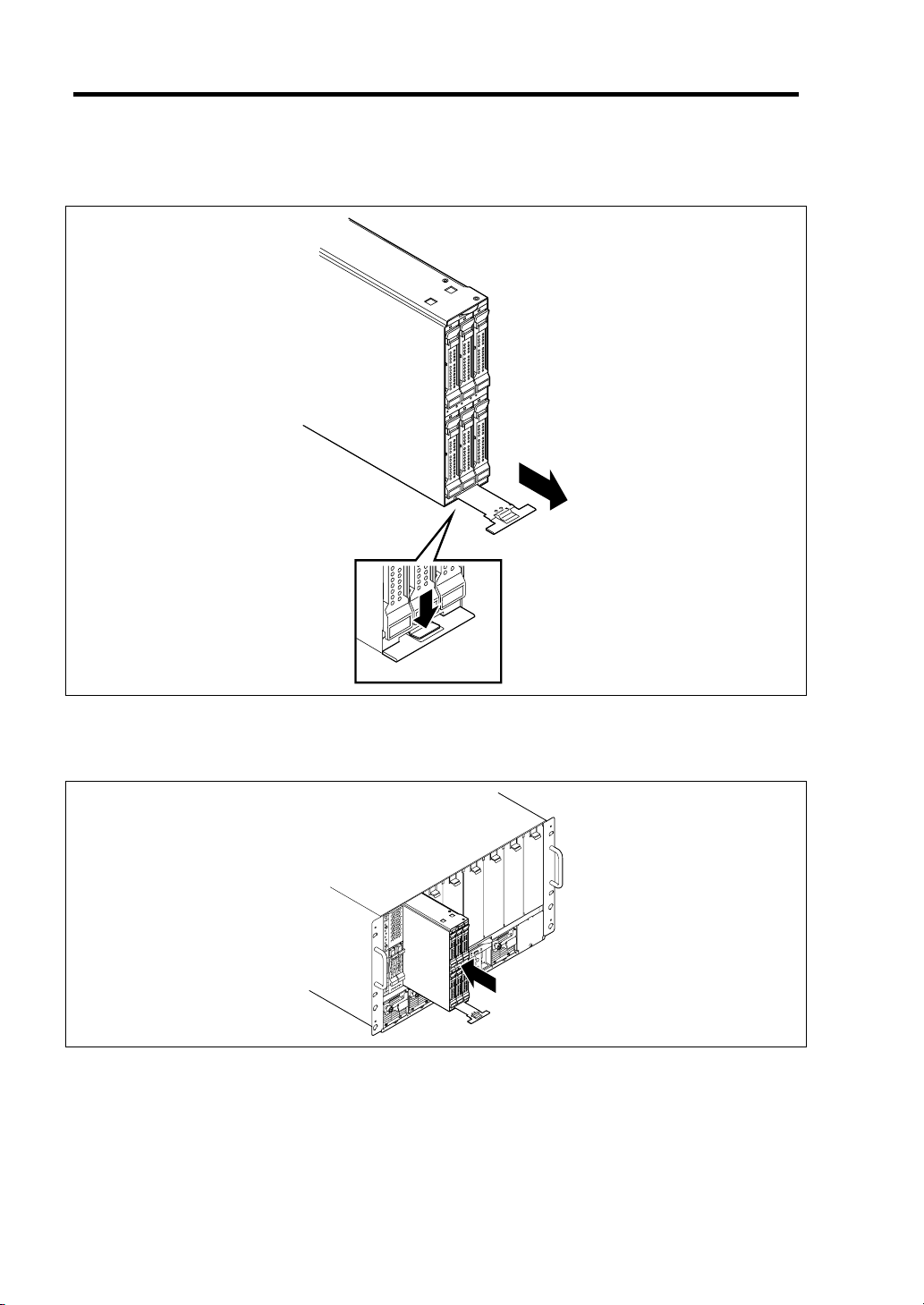
3-6 Setting Up Your Storage and I/O Blade
4. While pushing the eject button on the lower part of Storage and I/O Blade, pull the eject
lever toward you.
5. Insert the end of Storage and I/O Blade into the guide rails at top and bottom of the Blade
Enclosure, then push the Storage and I/O Blade slowly and carefully into the Blade
Enclosure.
6. Push the eject lever in the Storage and I/O Blade firmly.
Page 41

Setting Up Your Storage and I/O Blade 3-7
Removal
Power off the CPU blade to which the Storage and I/O Blade is being connected.
1.
IMPORTANT:
Be very careful to power off the CPU blade that is connected with
the Storage and I/O Blade you are going to remove.
You cannot install or remove the Storage and I/O Blade while the
CPU blade is being powered on.
NOTE: The power of the Storage and I/O Blade is automatically
turned off linking with the CPU blade.
2. While pushing the eject button on the lower part of Storage and I/O Blade, pull the eject
lever toward you.
IMPORTANT: Be sure to push the eject lever in the Storage and I/O
Blade.
Page 42

3-8 Setting Up Your Storage and I/O Blade
N8403-032 Joint Bracket for AD106a
To use the Storage and I/O Blade with the CPU blade that uses upper and lower two slots, an
optional N8403-032 joint bracket for AD106a is required.
Joint bracket for AD106a
NOTE: N8403-032 joint bracket for AD106a must be installed to the
Storage and I/O Blade in the lower stage of SIGMABLADE-H.
Page 43

Installation and Removal
Put N8403-032 joint bracket for AD106a with its hooks faces the top surface of Storage
1.
and I/O Blade.
Make sure that hooks on N8403-032 joint bracket for AD106a engage with holes on the
Storage and I/O Blade.
N8403-032 joint bracket for AD106a
Setting Up Your Storage and I/O Blade 3-9
Hook
2. Secure the N8403-032 joint bracket for AD106a together with the Storage and I/O Blade
to the rear of the chassis.
3. Remove the N8403-032 joint bracket for AD106a in reverse order of the installation steps.
Page 44

3-10 Setting Up Your Storage and I/O Blade
INSTALLING THE HARD DISK DRIVE
Install a hard disk drive according to the procedure described in Chapter 9.
IMPORTANT:
The hard disk drive is extremely sensitive to static electricity. Make
sure to touch the metal frame of the Storage and I/O Blade to
discharge static electricity from your body before handling the hard
disk drive. Do not touch the pins, leads, or circuitry and place the
hard disk drive directly on the desk. For static notes, see "Anti-static
Measures" in Chapter 9.
Some hard disk drive may contain operating system. Strict care
must be taken when handling it.
Handle the hard disk drive carefully so that the hard disk drive may
not be given excess shocks and vibrations.
Page 45

Chapter 4
Configuring Your Storage and I/O Blade
This chapter describes how to configure RAID system with hard disk drives installed in the Storage
and I/O Blade.
Page 46

4-2 Configuring Your Storage and I/O Blade
RAID SYSTEM CONFIGURATION
This section describes how to use the internal hard disk drives as RAID System by Internal RAID
Controller.
RAID
Overview of RAID System
What is RAID (Redundant Array of Inexpensive Disks)?
RAID can configure more than one HDDs as a single array (disk group) to operate the HDDs
effectively. This can bring higher performance than a single HDD of a large capacity.
The Internal RAID Controller has a feature to divide a single disk group into several logical drives
(virtual disks). Operating system recognizes these virtual disks as if it were a single hard disk drive.
Operating system accesses to more than one hard disk drive configuring a disk group in parallel.
Some RAID levels can recover data from remaining data and parity by using rebuild feature if an
error occurs in a single HDD. This can provide high reliability for the system.
Page 47

Configuring Your Storage and I/O Blade 4-3
RAID Levels
The record mode enabling the RAID feature includes several levels. Among the levels, the Internal
RAID Controller supports RAID levels 0, 1, 5, and 6. The number of hard disk drives required to
create a disk group varies depending on the RAID level as shown in the table below.
RAID level
Number of required HDDs
Min. Max.
RAID 0 1 6
RAID 1 2 2
RAID 5 3 6
RAID 6 3 6
NOTE: For details of the RAID levels, see "RAID Levels" described
later in this chapter.
Disk Group
A disk group is configured with more than one HDDs.
The allowable number of disk groups is equal to the number of HDDs.
The figure below shows a sample configuration. The three HDDs are connected to the Internal
RAID Controller, creating one disk group (DG).
RAID Controller
Disk Group 0: 108 GB
HDD 1
(36 GB)
HDD 2
(36 GB)
HDD 3
(36 GB)
Page 48

4-4 Configuring Your Storage and I/O Blade
Virtual Disk
Virtual disk is a logical drive defined in disk group. It is recognized as a physical drive by OS. The
allowable number of virtual disks is up to 16 per disk group, or up to 64 per controller.
The figure below shows a sample configuration in which the Internal RAID Controller is connected
with three HDDs, creating one Disk Group. Two RAID5 virtual disks (VD) are defined in the Disk
Group.
RAID Controller
DG0 108 GB
VD0-1
20GB
VD1-1
16 GB
HDD 1
(36 GB)
VD0-2
20GB
VD1-2
16 GB
HDD 2
(36 GB)
VD0-3
20GB
VD1-3
16 GB
HDD 3
(36 GB)
VD0 (RAID5)
40 GB
VD1 (RAID5)
32 GB
Parity
The parity means redundant data. A single set of redundant data is created from the data saved in
more than one HDD.
The created redundant data is used for data recovery when a HDD is defected.
Hot-Swap
The hot-swap enables a HDD to be removed (or replaced) under system operation.
Hot-Spare
The hot-spare is prepared as an auxiliary HDD substituting for a defected HDD included in a logical
drive which is configured at a redundant RAID level. Detecting a HDD fault, the system
disconnects the HDD (or makes it offline) and starts rebuild using the hot-spare.
Page 49

Configuring Your Storage and I/O Blade 4-5
RAID Levels
Characteristics of RAID Levels
The table below lists the characteristics of the RAID levels.
Level Function Redundancy Characteristics
RAID0 Striping No • Data read/write at the highest rate
• Largest capacity
• Capacity: (capacity of single HDD) ×
(number of HDDs)
RAID1 Mirroring Yes • Two HDDs required
• Capacity: capacity of single HDD
RAID5 Striping of both data
and redundant data
RAID6
Striping of both data
and redundant data
Yes • Three or more HDDs required
• Capacity: (capacity of single HDD) ×
((number of HDDs) - 1)
Yes
• Three or more HDDs required
• Capacity: (capacity of single HDD) ×
((number of HDDs) - 2)
Page 50

4-6 Configuring Your Storage and I/O Blade
RAID0
In RAID0, data to be recorded is distributed to HDDs. The mode is called "striping".
In the figure below, data is recorded in stripe 1 (disk 1), stripe 2 (disk 2), and stripe 3 (disk 3)… in
the order. Because RAID0 allows all HDDs to be accessed collectively, it can provide the best disk
access performance.
IMPORTANT: RAID0 cannot have data redundancy. If a HDD is
defected, the data saved in the HDD cannot be recovered.
RAID Controller
HDD 1 HDD 2
Stripe 1
Stripe 4
Stri pe 2
Stri pe 5
HDD 3
Stri pe 3
Stri pe 6
RAID1
In the RAID1 level, data saved in a HDD is written to another HDD without change. The mode is
called "mirroring".
When data is written onto a single HDD, the same data is written onto another HDD. If either of the
HDDs is defected, the other HDD containing the same data can substitute for the defected HDD.
Thus the system can continue to operate without interruption.
RAID Controller
HDD 1 HDD 2
Stripe 1
Stripe 2
Stripe 1
Stripe 2
Page 51

Configuring Your Storage and I/O Blade 4-7
RAID5
In RAID5, data is distributed to HDDs by striping and, at the same time, the parity (redundant data)
is distributed to the HDDs. This mode is called "striping with distributed parity".
Each of stripe x, stripe x+1, and parity (x, x+1) created from stripe x and stripe x+1 is written onto a
specific HDD. Accordingly, the total capacity assigned to the parity is just the same as the capacity
of a single HDD. If any one of the HDDs configuring a logical drive is defected, data is still
available with no problems.
RAID Controller
HDD 1 HDD 2 HDD 3
Stri pe 1
Stri pe 4
Parity (5, 6)
Stripe 2
Parity (3, 4)
Stripe 5
Parity (1, 2)
Stri pe 3
Stri pe 6
RAID6
A RAID 6 extends RAID 5 by adding an additional parity block (Q) created by different calculation
method such as weighting by some factor, thus it uses block-level striping with two parity blocks
distributed across all member disks. This mode is called "striping with duplex and distributed
parity". Accordingly, the total capacity assigned to the parity is just the same as the capacity of two
HDDs. If any two of the HDDs configuring a logical drive are defected, data is still available with
no problems.
RAID Controller
HDD 1 HDD 2
Stri pe 1
Stripe 2
HDD 3
Parity P (1,2)
HDD 4
Parity Q (1,2)
Stri pe 4
Parity P (5,6) Parity Q (5,6) Stripe 5
Parity Q (7,8) Stripe 7 Stripe 8 Parity P (7,8)
Parity P (3,4)
Parity Q (3,4)
Stripe 3
Stripe 6
Page 52

4-8 Configuring Your Storage and I/O Blade
Configuration by Internal RAID Controller
This section describes how to use the internal hard disk drives as RAID System by Internal RAID
Controller.
Features of Internal RAID Controller
Rebuild
If a HDD is defected, the rebuild feature can recover the data in the defected HDD. The rebuild can
be applied to redundant virtual disks in the RAID1, RAID5, or RAID6 level.
Manual Rebuild
The manual rebuild can be performed by using WebBIOS or Universal RAID Utility, the
management utility of the Internal RAID Controller. Select a HDD and start the rebuild manually.
For the detailed operation, refer to the "Universal RAID Utility
EXPRESSBUILDER DVD that comes with the CPU blade.
Auto Rebuild
Ver2.0 User's Guide" in NEC
The Internal RAID Controller can automatically start the rebuild without use of any utility such as
Universal RAID Utility.
The auto rebuild includes two types as follows:
Standby rebuild
Automatic rebuild by using hot-spares. In the configuration including hot-spares, the
rebuild is performed automatically if a HDD assigned to a virtual disk is defected.
Hot-swap rebuild
Automatic rebuild by hot-swapping defected HDD.
IMPORTANT: Note the following for the rebuild:
The HDD used for rebuild should have the same capacity, rotation
speed, and standard as the defected HDD.
During rebuild, the processing rate is decreased due to much load.
During rebuild, do not shutdown or reboot the CPU blade connected
with this Storage and I/O Blade. If the CPU blade is shutdown by an
unforeseen accident such as power interruption, turn on the power
again as soon as possible. The rebuild is automatically restarted.
The interval from the removal of the defected HDD to the
installation of a substitute HDD should be 60 seconds or longer.
If the hot-swap rebuild does not operate, perform the manual
rebuild.
Page 53

Configuring Your Storage and I/O Blade 4-9
Patrol Read
The patrol read gives the read & verify test in the entire area of HDDs. It can be performed for all
HDDs assigned to virtual disks and hot-spares.
The Patrol Read allows subsequent defects of HDDs to be detected and repaired.
For HDDs configuring redundant virtual disks or those assigned to hot-spares, error sectors detected
during Patrol Read can be repaired.
IMPORTANT: Note the following for the patrol read:
For the Internal RAID Controller, Patrol Read feature is factory-set
to "Enabled".
To change settings of Patrol Read, use Universal RAID Utility.
If the system is restarted while running Patrol Read, Patrol Read
resumes from that point.
Consistency Check
The Consistency Check is used to check consistency among virtual drives. It is available for
redundant virtual drives except for RAID0. It is also available for host spare.
Consistency Check can be performed through WebBIOS or Universal RAID Utility.
Consistency Check performs not only consistency check but also repair of error sectors.
Accordingly, it can be used as preventive maintenance.
IMPORTANT: Note the following for Consistency Check:
During Consistency Check, the processing rate is decreased due to
much load.
If the system is restarted, the Consistency Check is aborted.
However, the Consistency Check resumes after restart.
To schedule execution of Consistency Check, use WebBIOS.
Page 54

4-10 Configuring Your Storage and I/O Blade
Background Initialize
The Background Initialize is automatically executed when RAID5 virtual disk is created in the disk
group composing of five or more HDDs.
The Background Initialize performs the parity generation processing in the background to the area
not initialized. The processing is equivalent to that of Consistency Check.
However, the Background Initialize is not performed in the following cases.
Full Initialize has already been executed and completed normally before executing
Background Initialize.
(*) Full Initialize is a function to clear the entire area of a virtual disk with "0".
Consistency Check has already been executed and completed normally before executing
Background Initialize.
Rebuild has already been executed and completed normally before executing Background
Initialize (for RAID5 only).
"Yes" is specified for "Disable BGI" in VD Definition.
Virtual disk is in degraded or offline state.
Background Initialize is performed if the virtual disk of RAID6 is partially degraded.
The Background Initialize is executed again if any of the following cases occurred in the virtual
disk on which the Background Initialize has completed.
When the virtual disk is degraded or offline, you execute Make Online to HDD being in
offline status, and the virtual disk becomes Optimal state.
When you replace the RAID Controller with the maintenance parts and others.
When you execute Reconstruction to existing virtual disk to make RAID5 VD with five or
more HDDs.
IMPORTANT: Note the following for Background Initialize:
During Background Initialize, the processing rate is decreased due
to much load.
Background Initialize will resume a few minutes later even if it is
interrupted.
Page 55

Configuring Your Storage and I/O Blade 4-11
Reconstruction
The reconstruction feature is used to change configuration and/or RAID level of existing virtual
disk. The Reconstruction contains the following three features, however, the Internal RAID
Controller supports "Migration with addition" only.
IMPORTANT: You can use WebBIOS for Reconstruction. Universal
RAID Utility does not support Reconstruction.
Removed physical drive
Unsupported.
Migration only
Unsupported.
Migration with addition
Use this feature to add HDDs to existing virtual disk. The execution patterns are as shown
below (α: Number of HDDs to be added).
Before execution After execution
RAID
level
RAID0 x RAID0
Number of
HDDs
RAID
level
Number of
HDDs
x+α Capacity increased: equivalent to α HDDs
RAID0 1 RAID1 2 Capacity remains unchanged.
RAID0 x RAID5
RAID0 x RAID6
RAID1 2 RAID0
RAID1 2 RAID5
RAID1 2 RAID6
RAID5 x RAID0
RAID5 x RAID5
RAID5 x RAID6
RAID6 x RAID0
RAID6 x RAID5
RAID6 x RAID6
x+α Capacity increased: equivalent to α-1 HDDs
x+α
(α=2 or more)
2+α Capacity increased: equivalent to α+1 HDDs
2+α Capacity increased: equivalent to α HDDs
2+α Capacity increased: equivalent to α-1 HDDs
x+α Capacity increased: equivalent to α+1 HDDs
x+α Capacity increased: equivalent to α HDDs
x+α Capacity increased: equivalent to α-1 HDDs
x+α Capacity increased: equivalent to α+2 HDDs
x+α Capacity increased: equivalent to α+1 HDDs
x+α Capacity increased: equivalent to α HDDs
Description
Capacity increased: equivalent to α-2 HDDs
Page 56

4-12 Configuring Your Storage and I/O Blade
IMPORTANT: Note the following for the Reconstruction:
Be sure to make backup copy of data and perform Consistency
Check before starting Reconstruction.
The Reconstruction is disabled in the configuration where several
virtual disks are defined in one disk group
During Reconstruction, the processing rate is decreased due to much
load.
The Reconstruction can be performed for the degraded or partially
degraded virtual disk. However, it is recommended to execute
Rebuild to recover the virtual disk, then execute Reconstruction.
During Reconstruction, do not shutdown or reboot the CPU blade
connected with this Storage and I/O Blade. If the CPU blade is
shutdown by an unforeseen accident such as power interruption,
turn on the power again as soon as possible. The Reconstruction is
automatically restarted.
In some configuration, Background Initialize may start
automatically upon completion of Reconstruction.
Ex: Migration with addition for RAID5 virtual disk
The figure below shows an example of adding a single 36GB HDD to a RAID5 virtual disk
configured with three 36GB HDDs.
Virtual disk (RAID5)
[Before execution]
36GB 36GB 36GB
Virtual disk (RAID5)
36GB 36GB 36GB
36GB
Execute Migration with addition
36GB
Capacity = 72GB
[After execution]
Capacity = 108GB
Page 57

Configuring Your Storage and I/O Blade 4-13
Configuration on Disk (COD) Feature
Configuration on Disk (COD) feature is used to store the configuration information in hard disk
drive.
If the RAID controller is replaced with new one due to its failure, you can restore the configuration
information from the hard disk drive. Then, the RAID system can work normally.
NOTE: The Internal RAID Controller does not have the configuration
information. All the configuration information is stored in hard disk
drive.
Page 58

4-14 Configuring Your Storage and I/O Blade
Before Using WebBIOS
Read the following sections describing supported functions and precautions before using
"WebBIOS".
Supported Functions
Indication of model name and capacity of Hard Disk Drive
Indication of allocation status of Hard Disk Drive
Creation of virtual drive
– Setting of RAID level
– Setting of Stripe Block size
– Setting of Read Policy/Write Policy/IO Policy
Indication of configuration information and status of virtual drive
Removal of virtual drive
Clearing of configuration
Execution of initialization
Execution of Consistency Check
Execution of manual rebuild
Execution of reconstruction
Page 59

Configuring Your Storage and I/O Blade 4-15
Notes on Creating Virtual Drive
The Hard Disk Drives configuring the drive group should have the same capacity and
1.
rotation speed.
2. Be sure to execute Consistency Check after creating VD.
3. When installing an OS in VD under the Internal RAID Controller, create a VD dedicated
to OS installation.
4. WebBIOS cannot be used via remote console functions of NEC ESMPRO Manager.
5. The physical drive numbers shown in WebBIOS and those shown in Universal RAID
Utility are identified as follows.
– WebBIOS
Slot number shown in Physical View
*1: The slot number, type of Hard Disk Drive, its capacity, and its current status are
shown in Physical View.
The slot number is indicated by the number 0 to 5. It represents the slot number in
the Hard Disk Drive bay.
*1
– Universal RAID Utility
ID shown in Physical Device Properties
The slot number shown on WebBIOS corresponds to the physical device ID shown
on Universal RAID Utility. For more information, refer to the Universal RAID
Utility Ver2.0 User's Guide.
Physical View of WebBIOS
Page 60

4-16 Configuring Your Storage and I/O Blade
Property of Physical Device of Universal RAID Utility
Page 61

Using WebBIOS
Starting WebBIOS
When the screen as shown below appears, press Ctrl + H to start WebBIOS.
1.
LSI MegaRAID SAS - MFI BIOS
Version XXXX (Build MMM DD, YYYY)
Copyright (c) 20XX LSI Corporation
HA - X (Bus X Dev X) MegaRAID SAS 8708EM2
FW package: X.X.X - XXXX
0 Virtual Drive(s) found on the host adapter.
0 Virtual Drive(s) handled by BIOS.
Press <Ctrl> <H> for WebBIOS.....
POST screen image (with no virtual drive assigned)
IMPORTANT:
Configuring Your Storage and I/O Blade 4-17
Do not press unnecessary key such as Pause during POST.
If you fail to press Ctrl + H or the system proceeds without
displaying the WebBIOS main menu (shown on the next page),
reboot the CPU blade connected with this Storage and I/O Blade,
and press Ctrl + H on POST screen.
Page 62

4-18 Configuring Your Storage and I/O Blade
Main Menu
Shown below is [Adapter Selection] screen that appears first on WebBIOS. On [Adapter No.] box,
select an adapter you want to operate with WebBIOS, then click [Start].
When the adapter is selected on [Adapter Selection], the WebBIOS Top Menu appears.
Information of VD configured and
physical devices connected with the
controller.
Page 63

Configuring Your Storage and I/O Blade 4-19
WebBIOS Menu
Controller Selection Goes back to Adapter Selection menu.
Controller Properties Displays properties of the controller.
Scan Devices Detects Hard Disk Drives connected with the controller again.
Virtual Drives Opens operation window for VD that has already been configured.
Drives
Configuration Wizard Displays the wizard to configure VD.
Physical View /
Logical View
Events Displays event data.
Exit Goes to Exit menu of WebBIOS.
Opens operation window for Hard Disk Drive connected with the
controller.
Switches indication between Hard Disk Drives and VD
configuration.
Status Indication of Virtual Drive (not shown on Physical View)
Optimal Indicates that the VD is in normal state.
The indication is green.
Partially Degraded Indicates that one of the Hard Disk Drives in the relevant VD is
degraded in RAID6 configuration.
The indication is blue.
Degraded Indicates that one or two of the Hard Disk Drives in the relevant VD
is degraded in RAID6 configuration.
The indication is blue.
Offline The relevant VD is in offline state.
The indication is red.
Initialization The relevant VD is being initialized.
ConsistencyCheck Consistency Check is being performed to the relevant VD.
Rebuild The relevant VD is being rebuilt.
BackGroundInitialize The relevant VD is being initialized in background.
Reconstruction The relevant VD is being reconstructed.
Status Indication of Hard Disk Drive
Unconfigured Good The Hard Disk Drive connected with the controller is not in use.
The indication is blue.
Online Indicates that the Hard Disk Drive in configuration is in normal
state.
The indication is green.
Offline Indicates that the Hard Disk Drive in configuration is in offline state.
The indication is red.
Unconfigured Bad The relevant Hard Disk Drive is faulty.
(The Hard Disk Drive in this status can be checked only on
Physical View.)
The indication is black.
Rebuild The relevant Hard Disk Drive is being rebuilt.
The indication is yellow.
Hotspare Indicates the Hard Disk Drive that is assigned to hot-spare.
The indication is pink.
Page 64

4-20 Configuring Your Storage and I/O Blade
IMPORTANT:
The right frame of Physical View shows slot number, type, capacity,
and status of Hard Disk Drive.
The slot number is represented by the number between 0 and 5. It
indicates the slot number of the Hard Disk Drive bay.
The controller does not support the Events feature.
NOTE: S.M.A.R.T status
The information of the Hard Disk Drive that has one or more Pred
Fail Count is displayed in yellow.
Indicates that the device has failed in the past. You can use the
device as usual, however, we recommend you to replace it with new
one.
Page 65

Configuring Your Storage and I/O Blade 4-21
Controller Properties
When you click [Controller Properties] on WebBIOS Top Menu, the configuration information is
displayed.
Click [Next] to see the detailed settings of this controller.
Page 66
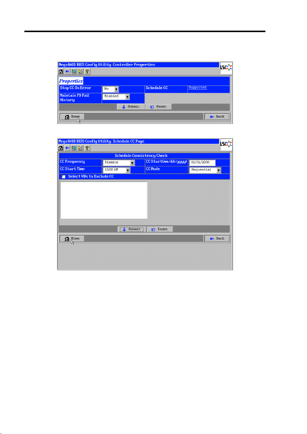
4-22 Configuring Your Storage and I/O Blade
The detailed setting is continued on the next page. Click [Next] to view more information.
Clicking [Supported] in "Schedule CC" opens the screen for setting scheduled consistency check.
Page 67

Configuring Your Storage and I/O Blade 4-23
Default settings and their explanation
Item Default Description Change
Battery Backup Present
None
Set Factory Defaults No – Prohibited
Cluster Mode Disabled – Prohibited
Rebuild Rate 30 Recommended value: 30 Permitted
BGI Rate 30 Recommended value: 30 Permitted
CC Rate 30 Recommended value: 30 Permitted
Reconstruction Rate 30 Recommended value: 30 Permitted
Controller BIOS Enabled – Prohibited
NCQ Disabled – Prohibited
Coercion Mode None – Prohibited
S.M.A.R.T Polling 300 – Prohibited
Alarm Control Disabled Disabled: Does not issue an alarm.
Patrol Read Rate 30 Recommended value: 30 Permitted
Cache Flush
4 – Prohibited
Interval
Spinup Drive Count 2 – Prohibited
Spinup Delay 12 – Prohibited
StopOnError Disabled – Prohibited
Drive Powersave Disabled – Prohibited
Stop CC On Error No
Yes
Maintain PD Fail
Enabled – Prohibited
History
Schedule CC Supported Set the scheduled consistency check. Permitted
CC Frequency Disabled Set the interval of scheduled
CC Start Time 12:00 AM Set the time to start the first consistency
Displays Properties of additional
battery.
• When battery is installed: Present
• When battery is not installed: None
Enabled: Issues an alarm.
Silence: Stops an alarm if beeped.
Specify the operation at error detection
in Consistency Check.
No: Recover and resume.
Yes: Abort
consistency check.
*3
Disabled: Disables the scheduled
consistency check.
Continuous: Checks consistency
continuously.
Hourly: Checks consistency every hour.
Daily: Checks consistency every day.
Weekly: Checks consistency every
week (recommended value).
Monthly: Checks consistency every
month (recommended value).
check.
–
Permitted
Permitted
Permitted
Permitted
*1
*2
Page 68

4-24 Configuring Your Storage and I/O Blade
Item Default Description Change
Select VDs to
Exclude CC
CC Start
(mm/dd/yyyy)
CC Mode Sequential Sequential: Consistency check is
*1 Do not perform "Set Factory Defaults". If performed, the NEC's factory-set value will no longer
be restored.
*2 If Alarm Control is set to "Enabled", the CPU blade issues an alarm sound when the VD is
degraded due to failure of Hard Disk Drive.
*3 Set interval of scheduled consistency check in "CC Frequency" with sufficient allowance
because it is based on "CC Start Time".
Unchecked Specify the VD to which the scheduled
consistency check is not performed.
Checked: Consistency check is not
performed on the selected VD.
Unchecked: Consistency check is
performed on every VD.
01/01/2000 Set the date to start the first consistency
check.
performed on several VDs sequentially.
Concurrent: Consistency check is
performed on several VDs
simultaneously.
Permitted
Permitted
Permitted
Page 69

Configuring Your Storage and I/O Blade 4-25
How to change setting value
On [Controller Properties] screen, change a parameter to desired value, and then click [Submit] at
the center of the screen to determine the new value.
With Storage and I/O Blade, the status of "Battery Backup" is indicated as "Present". Clicking
[Present] opens the Battery Status screen as shown below.
IMPORTANT: You cannot change values for "Auto Learn Period",
"Next Learn Time", and "Learn Delay Interval".
NOTES:
The value shown in "Current" field indicates battery status.
– Positive value: Battery is being charged
– Negative value: Battery is being discharged.
WebBIOS does not refresh the indication on window. To view the
indication, change window (e.g., go back to Top Menu), then check
status again.
Page 70

4-26 Configuring Your Storage and I/O Blade
Scan Devices
When you click [Scan Devices] on WebBIOS Top Menu, the connected Hard Disk Drives are
detected again. Use this feature when you have installed a new Hard Disk Drive additionally while
the WebBIOS is running.
IMPORTANT:
If the newly connected Hard Disk Drive contains another
configuration information, [Foreign Configuration] screen as shown
below appears. To use the Hard Disk Drive as new one, click [Clear]
to clear the configuration information in Hard Disk Drive.
If you want to create a logical drive by using the Universal RAID
Utility with the newly connected Hard Disk Drive containing
another configuration information, first clear another configuration
information using this Scan Devices feature.
(*) Universal RAID Utility does not have this feature.
Page 71

Configuring Your Storage and I/O Blade 4-27
Virtual Drives
When you click [Virtual Drives] on WebBIOS Top Menu, the screen for operating the VD that has
already been configured. List of VDs box shows existing VDs.
List of VDs
Fast Initialize
Slow Initialize
Check Consistency
Properties
Set Boot Drive
(Current =XX)
Default: NONE
IMPORTANT:
If no virtual drive exists, the List of VDs box will be blank. Use this
menu only when a virtual drive exists.
Even the "Set Boot Drive" is properly specified, the operating
system may fail to start due to Boot Priority specified in BIOS
SETUP of the CPU blade connected with this Storage and I/O
Blade.
Inconsistency may be detected at the first Check Consistency
performed after the VD was configured.
Clears the top area of the VD being selected in List of VDs box.
Clears whole area of the VD being selected in List of VDs box.
Checks consistency in the whole area of the VD being selected in List of
VDs box.
If inconsistency is found, correct it.
Displays the properties of the VD being selected in List of VDs box.
Selects a VD to start operating system.
If the system contains several VDs and you want to start the operating
system from the VD other than VD0, you need to specify the boot drive
manually as shown below. Use the default setting in any other cases.
[Setting procedure]
1. Select a VD you want to start operating system from the List of VDs box.
2. Put a checkmark on "Set Boot Drive (Current =XX)".
3. Click [Go].
Page 72

4-28 Configuring Your Storage and I/O Blade
Drives
When you click [Drives] on WebBIOS Top Menu, the screen for operating the connected physical
drive appears.
IMPORTANT: If no device is connected, the upper right column of
the screen will be blank. Use this menu only when a Hard Disk Drive is
being connected.
Page 73

Configuring Your Storage and I/O Blade 4-29
Physical Drive Properties
Take the following procedures to check Physical Drive Properties. Shown below is an example to
check property of physical drive.
1. Click the Physical Drive you want to check.
2. Click the checkbox for [Properties].
3. Click [Go].
The Properties screen as shown below appears.
Page 74

4-30 Configuring Your Storage and I/O Blade
Physical Drive Properties
Item Description
Locate Let Disk Status lamp light or blinks.
Make Global HSP The selected Hard Disk Drive is assigned as hot-spare available for all
DGs.
Make Dedicated HSP The selected Hard Disk Drive is assigned as hot-spare available only for
the specific DG.
Remove HOTSPARE The selected Hard Disk Drive is unassigned from hot-spare and made
Unconfigured Good state.
Make Unconf Bad Make the selected Hard Disk Drive in faulty state. This is indicated on
the Hard Disk Drive of which status is "Unconfigured Good".
Make Unconf Good Make the selected Hard Disk Drive in "Unconfigured Good" state. This is
indicated on the Hard Disk Drive of which status is "Unconfigured Bad".
Prepare Removal Make the power status of the selected Hard Disk Drive in "Powersave"
state.
This is indicated on the Hard Disk Drive of which power status is "On"
and the status is "Unconfigured Good".
Undo Removal Make the power status of the selected Hard Disk Drive in "On".
This is indicated on the Hard Disk Drive of which power status is
"Powersave".
Make Dive Offline Make the selected Hard Disk Drive in "Offline" state.
This is indicated on the Hard Disk Drive of which status is "Online".
Make Drive Online Make the selected Hard Disk Drive in "Online" state.
This is indicated on the Hard Disk Drive of which status is "Offline".
Rebuild Drive Start rebuilding VD that contains the selected Hard Disk Drive.
This is indicated for the Hard Disk Drive of which status is "Offline".
Mark as Missing Remove the VD that contains the selected Hard Disk Drive from the DG.
This is indicated on the Hard Disk Drive of which status is "Offline".
IMPORTANT: The RAID Controller does not support Events feature.
Page 75

Configuring Your Storage and I/O Blade 4-31
Configuration Wizard
Use this wizard to configure a virtual drive using the Hard Disk Drives connected. The detailed
explanation of this feature is given in "Configuring Virtual Drive".
Controller Selection
You may need to select an adapter controlled by WebBIOS to configure each adapter. Clicking
[Controller Selection] on WebBIOS top menu opens the [Adapter Selection] screen.
Physical View / Logical View
If the virtual drive has been configured, DG (drive group) is displayed on WebBIOS Top Menu.
Clicking [Physical View] displays information for Hard Disk Drives in DG. Clicking [Logical View]
displays virtual drive in DG.
Events
The Events screen is used to confirm the system events.
IMPORTANT: The RAID Controller does not support Events feature.
Page 76
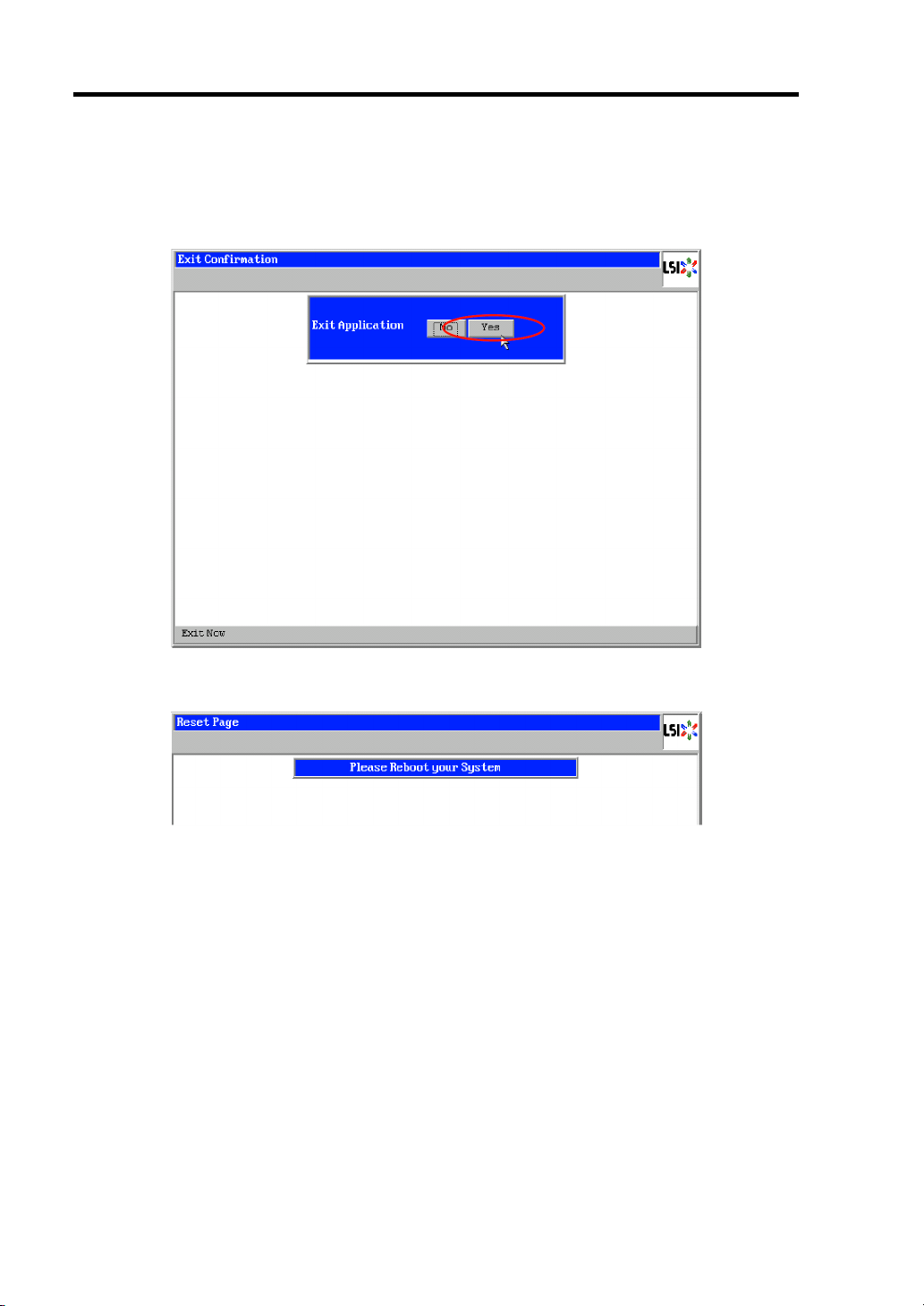
4-32 Configuring Your Storage and I/O Blade
Exit
When you click [Exit] on WebBIOS Top Menu, a confirmation screen to exit from WebBIOS is
displayed. Click [Yes] to exit from WebBIOS.
The screen as shown below appears when WebBIOS is terminated. Restart the CPU blade connected
with this Storage and I/O Blade.
Page 77

Configuring Your Storage and I/O Blade 4-33
Configuring Virtual Drive
This section describes the procedures for configuration of VD (virtual drive) using WebBIOS.
Configuration Wizard
When you click [Configuration Wizard] on WebBIOS Top Menu, the screen as shown below
appears. Select the relevant operation, and click [Next] at lower right of the screen.
Clear Configuration Allows you to clear existing configuration (RAID information).
New Configuration Clears the existing configuration and creates a new VD.
Add Configuration Retains the old VD and then adds new virtual drive.
IMPORTANT: If you create a VD by New Configuration, any
existing data in the earlier defined drives will be lost.
Page 78

4-34 Configuring Your Storage and I/O Blade
When you select [Add Configuration], the screen as shown below appears.
Be sure to select [Manual Configuration], and click [Next].
IMPORTANT: The RAID Controller does not support "Automatic
Configuration" feature.
Use this menu to define several Hard Disk Drives as a drive group (DG).
1. While pressing Ctrl, click the Hard Disk Drives to be included in DG.
Page 79

Configuring Your Storage and I/O Blade 4-35
2. Upon completion of selection, click [Add to Array] at the lower left of the screen.
3. A new DG is defined in the Drive Groups frame. To define the new DG, click [Accept
DG] at the lower right of the screen.
4. After the DG has been defined, click [Next] at the lower right of the screen.
Page 80

4-36 Configuring Your Storage and I/O Blade
5. Then, the Span Definition screen appears.
6. Select a DG to define VD from "Array With Free Space" frame, then click [Add to SPAN].
The DG is defined in the "Span" field to the right.
7. After the Span has been defined, click [Next] at the lower right of the screen.
DG is added to Span.
Page 81

Configuring Your Storage and I/O Blade 4-37
IMPORTANT:
To configure RAID0, 1, 5, or 6, perform Span Definition to a single
DG only. If you need to perform Span Definition to several DGs,
define VD for the first DG, then select the next DG to define VD.
To configure RAID10 or 50, select several DGs containing the same
number of Hard Disk Drives for Span Definition.
Span Definition cannot be performed to DGs containing the
different number of Hard Disk Drives.
Define the virtual drive (VD) in DG that has been created in previous step. When DG was defined,
[VD Definition] screen is displayed. In the "Next LD, Possible RAID Levels" column, available
RAID levels and maximum size for VD are displayed.
As an example, define a RAID5 VD of 135.312GB.
1. Specify the necessary parameters in left columns.
2. Enter "135.132" in "Select Size" field, and select "GB" as a unit.
3. Click [Accept] at the lower center of the screen.
4. If you want to define another VD, click [Back] and repeat steps starting from Span
Definition screen.
IMPORTANT: The value shown in "Select Size" indicates the
maximum size allowed for RAID1 (two Hard Disk Drives) or RAID6
(three or more Hard Disk Drives). You need to specify the maximum
size for any other RAID levels according to "Next LD, Possible RAID
Levels".
Page 82

4-38 Configuring Your Storage and I/O Blade
5. Upon completion of VD definition, click [Next].
IMPORTANT:
RAID1 may be configured with three or more Hard Disk Drives in
drive group. However, with this controller, the drive group must
contain only two Hard Disk Drives.
WebBIOS does not support the RAID6 logical drive having Stripe
Size: 8KB composed of three Hard Disk Drives.
Page 83

Configuring Your Storage and I/O Blade 4-39
6. VD is created in DG as shown in the screen below.
After making sure that the VD is created correctly, click [Accept] at the lower right of the
screen.
7. The confirmation message "Save this Configuration?" appears. Click [Yes] to save the
configuration.
8. The confirmation message "Want to Initialize the New Virtual Drives?" appears. To
perform "Fast Initialize", select [Yes].
9. "Virtual Drives" operation screen is displayed. If no other operation is required, click
[Home] at the lower left of the screen.
Page 84

4-40 Configuring Your Storage and I/O Blade
10. WebBIOS Top Menu is displayed. Virtual Drives you have created is displayed in the right
frame of the screen.
Page 85

Configuring Your Storage and I/O Blade 4-41
Configure SPAN
The following explains the sample procedure to configure RAID10 (spanning of RAID1) with four
Hard Disk Drives.
IMPORTANT: Do not attempt to configure RAID00 or RAID60.
They are not supported.
1. Click [Configuration Wizard] on WebBIOS Top Menu to start Wizard.
2. While pressing Ctrl, click the Hard Disk Drives to be included in DG.
(In the example, two DGs will be configured and spanned.)
3. Upon completion of selection, click [Add to Array] at the lower left of the screen. After
making sure that the new DG has been defined in Drive Groups frame to the right, click
[Accept DG].
Page 86

4-42 Configuring Your Storage and I/O Blade
4. A new DG is defined in the Drive Groups frame. Define another DG in the similar
procedures. After DGs have been defined, click [Next] at the lower right of the screen.
5. When DGs were defined, [Span Definition] screen is displayed.
6. Select DG0 from "Array With Free Space" frame, then click [Add to SPAN]. The DG is
defined in the "Span" field to the right.
Page 87

Configuring Your Storage and I/O Blade 4-43
7. Then, select DG1 and click [Add to SPAN]. When the two DGs are defined in the "Span"
field to the right, click [Next] at the lower right of the screen.
8. The VD Definition screen is displayed. Enter the necessary parameters, and click
[Accept].
Page 88

4-44 Configuring Your Storage and I/O Blade
9. Make sure that both DG0 and DG1 are defined as VD 0, then click [Next] at the lower
right of the screen.
IMPORTANT: RAID10 may be configured with three or more Hard
Disk Drives in each span. However, with this controller, each drive
group must contain only two Hard Disk Drives.
10. On the "Preview" screen, make sure the VD is defined correctly, then click [Accept] at the
lower right of the screen.
Page 89

Configuring Your Storage and I/O Blade 4-45
11. The confirmation message "Save this Configuration?" appears. Click [Yes] to save the
configuration.
12. The confirmation message "All data on the new Virtual Drives will be lost. Want to
Initialize?" appears. Click [Yes] to perform "Fast Initialize".
13. "Virtual Drives" operation screen is displayed. If no other operation is required, click
[Home] at the lower left of the screen.
14. The WebBIOS Top Menu is displayed. Virtual Drives you have created are displayed in
the right frame of the screen.
Page 90
4-46 Configuring Your Storage and I/O Blade
Parameters for VD Definition
Listed below are parameters for Configuration Wizard.
Item Parameter Remarks
RAID Level
Strip Size
Access Policy
Read Policy
Write Policy
WrtThru for BAD
BBU
IO Policy
Disk Cache
Policy
Disable BGI
RAID 0 / RAID 1 / RAID 5 / RAID 6 / RAID 00
/ RAID 10 / RAID 50 / RAID60
8 KB / 16 KB / 32 KB / 64 KB / 128 KB / 256
KB / 512 KB / 1024 KB
RW / Read Only / Blocked
Normal / Ahead / Adaptive
WBack / Wthru
Checked / Unchecked Select a mode when WriteBack
Direct / Cached
Unchanged / Enabled / Disabled
No / Yes
RAID 00 and RAID 60 are not
supported.
Recommended value: 64KB
Recommended value: RW
Recommended value: Normal
WBack: WriteBack
WThru: WriteThru
is specified for Write Policy.
Checked: Normal WriteBack
Unchecked: Constant
WriteBack
Recommended value:
Checked
Recommended value: Direct
Recommended value:
Disabled
Specify whether to perform
Background Initialize after
creation of VD.
Recommended value: No
IMPORTANT: BGI (Back Ground Initialize) is available only for the
following VDs:
– RAID5 VD configured with five or more physical devices.
Page 91

Configuring Your Storage and I/O Blade 4-47
The Write Policy has the following modes depending on combination with WrtThru for BAD BBU.
Select a mode suitable for your environment.
WrtThru forBAD BBU
Checked Unchecked
Write
Policy
WBack
WThru Write through mode
Normal write back mode
(recommended)
The controller uses cache memory
for writing. However, if the battery is
being charged or failed, the
controller operates in WThru (write
through) mode automatically. Thus,
this mode can provide higher data
security.
The controller does not use cache
memory for writing data.
This mode can provide the highest
data security, however, the writing
performance is lower than that in
write back mode.
Constant write back mode
The controller always uses cache
memory for writing regardless of
battery charged status or existence
of battery.
Be sure to use UPS when specifying
this mode for write policy.
* This mode is unavailable.
If you do not check "WrtThru for BAD
BBU" at creation of VD, this item is
automatically checked after the VD
has been created.
IMPORTANT:
If constant write back mode is selected, the controller operates in
write back mode even if the battery has failed or insufficiently
charged. The data in cache memory may be lost at an occurrence of
power failure.
Be sure to use UPS when specifying the constant write back mode
for write policy.
Page 92

4-48 Configuring Your Storage and I/O Blade
The Disk Cache Policy has the following modes. Select a mode suitable for your environment.
Unchanged • The controller uses the default write cache policy of hard disk drive.
• The default value may not be identical to the factory-set value, therefore, do not
specify this mode.
Enabled • The controller always uses the write cache policy of hard disk drive.
• Be sure to use UPS when specifying this mode for disk cache policy.
Disabled • The controller does not use the write cache policy of the hard disk drive.
• This mode can provide the highest data security, however, the writing
performance is lower than that in Enabled mode.
• It is recommended to use this mode for the sake of data security.
IMPORTANT:
If "Unchanged" is specified for Disk Cache Policy, the default value
may not be identical to the factory-set value, therefore, do not
specify this mode.
If Enabled is specified for Disk Cache Policy, the controller uses the
write cache policy of the hard disk drive. Accordingly, the data in
cache memory of the hard disk drive may be lost at an occurrence of
power failure.
Be sure to use UPS when using the cache memory of the hard disk
drive.
You can change parameters for VD definition except for RAID Level and Stripe Size. On the
WebBIOS Top Menu, click [Virtual Drives] and specify parameters in "Policies" frame, then click
[Change].
Page 93
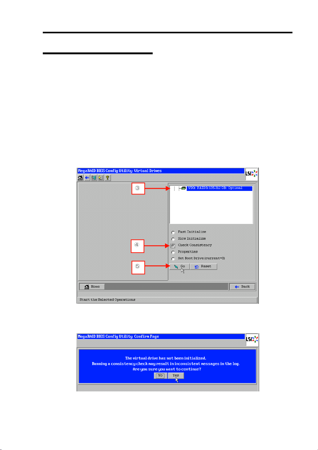
Configuring Your Storage and I/O Blade 4-49
Operation of Various Features
Check Consistency
Check Consistency is used to check consistency among virtual drives.
1. Start WebBIOS on POST screen of CPU blade.
2. Click [Virtual Drives] on WebBIOS Top Menu.
3. Select a VD to perform Check Consistency from the upper right frame of Virtual Drives
screen.
4. Click the checkmark column for Check Consistency from the lower right frame of Virtual
Drives screen.
5. Make sure that Check Consistency is checked, and click [Go].
6. Inconsistency may be detected at Check Consistency performed immediately after the VD
was configured. If the following alert is displayed, click [Yes] to perform Check
Consistency. A lot of inconsistency may be detected, however, it is not a failure.
Page 94

4-50 Configuring Your Storage and I/O Blade
7. The progress of Check Consistency is displayed on the left frame of Virtual Drives screen.
8. Click [Home] at the lower left of Virtual Drives screen to return to the Top Menu.
IMPORTANT: A lot of inconsistency may be detected at Check
Consistency performed immediately after the VD was configured due to
inconsistencies in the unused area. In such a case, an alert may be
logged.
Page 95

Configuring Your Storage and I/O Blade 4-51
Manual Rebuild
Rebuild can be performed automatically when the failed Hard Disk Drive is replaced in hot-swap
mode. However, if the failed Hard Disk Drive is replaced after turning off the power of the CPU
blade connected with this Storage and I/O Blade, Rebuild will not start automatically. Use Manual
Rebuild feature to recover the virtual drives as described below.
IMPORTANT:
To perform rebuild by replacing the Hard Disk Drive in hot-swap
mode, be sure to replace the device while the operating system or
WebBIOS is running.
You can view the progress of rebuild process on Universal RAID
Utility screen or click [Virtual Drive] on WebBIOS Top Menu.
With the progress indication being displayed, the rebuild may be
processed at slow rate. Go to WebBIOS Top Menu after making
sure the rebuild progress.
Page 96

4-52 Configuring Your Storage and I/O Blade
Described below are procedures based on assumption:
One of the Hard Disk Drives failed in a RAID5 VD configured with three Hard Disk Drives.
Replace the failed Hard Disk Drive with new one after turning off the power of the CPU blade
connected with this Storage and I/O Blade. Auto Rebuild feature is disabled for non-hot-swap
replacement. Use Manual Rebuild feature to recover the virtual drives as described below.
1. Start WebBIOS on POST screen of CPU blade.
Make sure that the status for the replaced Hard Disk Drive is indicated as "Unconfigured
Good" in the right frame of the Top Menu.
In the example below, the Hard Disk Drive in slot number 2 has been replaced.
The indication "PD Missing: BackPlane 252: Slot2" represents that the Hard Disk Drive
in VD having been installed in slot number 2 was removed.
2. Select the newly connected Hard Disk Drive (the Hard Disk Drive in slot number 2 in the
example) from the right frame of Top Menu.
3. The properties for Physical Drive is displayed.
Page 97

Configuring Your Storage and I/O Blade 4-53
4. Check to "Make Global HSP" or select the DG you want to rebuild and check to "Make
Dedicated HSP", and then click [Go] on the lower center of the screen.
– Check to "Make Global HSP" check
box.
Or, select the DG that contains the
failed physical device and check to
"Make Dedicated HSP" check box.
5. When [Rebuild Progress] is displayed, click [Home] at the lower left of the screen to go
back to WebBIOS Top Menu.
IMPORTANT: Click [Home] while the background task such as
Consistency Check, Rebuild, or Reconstruction is being executed. With
the progress indication being displayed, the background task may be
processed at slow rate.
Page 98

4-54 Configuring Your Storage and I/O Blade
6. The WebBIOS Top Menu changes as shown below during rebuild. If you click on
Physical Drive being rebuilt, the progress of rebuild is displayed.
7. When the rebuild completes, the status for the Physical Drive is "Online" and that of the
Virtual Drive is "Optimal".
Page 99

Configuring Your Storage and I/O Blade 4-55
Setting Hot Spare
Described below are procedures based on assumption:
Add a Hard Disk Drive to a RAID5 VD configured with three Hard Disk Drives and assign a newly
added Hard Disk Drive as Hot Spare Disk.
1. Start WebBIOS on POST screen of CPU blade.
Make sure that the status for the added Hard Disk Drive is indicated as "Unconfigured
Good" in the right frame of the Top Menu.
2. Select the newly connected Hard Disk Drive (the Hard Disk Drive in slot number 3 in the
example) from the right frame of Top Menu.
3. The properties for Physical Drive is displayed.
Page 100

4-56 Configuring Your Storage and I/O Blade
4. Check to "Make Global HSP" or select the DG you want to specify as Hot Spare and
check to "Make Dedicated HSP", and then click [Go] on the lower center of the screen.
Global HSP Indicates the Hot Spare available for all DGs.
Dedicated HSP
Indicates the Hot Spare available only for the specific DG.
You need to specify the target DG.
– Check to "Make Global HSP" check
box.
Or, select the DG you want to specify
as Hot Spare and check to "Make
Dedicated HSP" check box.
5. The status for the newly connected Hard Disk Drive changes to "GL HOTSPARE" or
"DED HOTSPARE".
 Loading...