


PART NO. 599910667
SERVICE MANUAL
COLOR MONITOR
AccuSync
TM
LCD71VM
MODEL ID LCD71VM(A)/-BK(A)/-BK(B)
1st Edition
NEC-MITSUBISHI ELECTRIC VISUAL SYSTEMS CORPORATION
JULY 2003
200309
08R610AY
08R620AY
08R620BY
The SERVICE PERSONNEL should have the appropriate technical training, knowledge and experience
necessary to:
• Be familiar with specialized test equipment, and
• Be careful to follow all safety procedures to minimize danger to themselves and their coworkers.
To avoid electrical shocks, this equipment should be used with an appropriate power cord.
This equipment utilized a micro-gap power switch. Turn off the set by first pushing power switch. Next,
remove the power cord from the AC outlet.
To prevent fire or shock hazards, do not expose this unit to rain or moisture.
This symbol warns the personnel that un-insulated voltage within the unit may have sufficient
magnitude to cause electric shock.
This symbol alerts the personnel that important literature concerning the operation and
maintenance of this unit has been included.
Therefore, it should be read carefully in order to avoid any problems.
WARNING
PRODUCT SAFETY CAUTION
1. When parts replacement is required for servicing, always use the manufacturer's specified replacement.
2. When replacing the component, always be certain that all the components are put back in the place.
3. As for a connector, pick and extract housing with fingers properly since a disconnection and improper
contacts may occur, when wires of the connector are led.
4. Use a proper screwdriver. If you use screwdriver that does not fit, you may damage the screws.

CONTENTS
USER'S MANUAL -------------------------------------------------------------------- 1-1
SERIAL NUMBER INFORMATION ---------------------------------------------- 2-1
DISASSEMBLY ----------------------------------------------------------------------- 3-1
ADJUSTMENT PROCEDURES --------------------------------------------------- 4-1
INSPECTION ---------------------------------------------------------------------------- 5-1
TROUBLE SHOOTING -------------------------------------------------------------- 6-1
CIRCUIT DESCRIPTION ------------------------------------------------------------ 7-1
Page No.
REPLACEMENT PARTS LIST ---------------------------------------------------- 8-1
BLOCK DIAGRAM ------------------------------------------------------------------- 9-1
SCHEMATIC DIAGRAMS ---------------------------------------------------------- 10-1
PACKING SPECIFICATION -------------------------------------------------------- 11-1
User's Manual
1. A Version
AccuSync
TM
LCD51VM/LCD71VM
1-1

W
Content
k
3
C
ded
Sp
ecif
F
Tr
eferences .............................................................................................................16
C
Av
Cont
h
Co
é
0
t
ions
32
é
éfé
Ga
r
7
Index
arning .................................................................................................................... 1
s ................................................................................................................. 2
Start .............................................................................................................
Quic
ontrols ...................................................................................................................7
Recommen
eatures ............................................................................................................... 14
oubleshooting ................................................................................................... 15
R
Limited Warranty................................................................................................. 17
O ‘99 .................................................................................................................. 18
T
ertissement ......................................................................................................21
Mise en marc
mmandes .......................................................................................................... 27
Usage recommand
Spécifica
Fonctions ............................................................................................................. 34
D
pannage ............................................................................................................ 35
rences ........................................................................................................... 36
R
antie limitée .................................................................................................. 3
TCO ‘99 .................................................................................................................. 38
Use.............................................................................................. 10
ications .......................................................................................................12
enu................................................................................................................. 22
e rapide ...................................................................................... 23
............................................................................................ 3
......................................................................................................
1-2
N
(
N
s
symbol warns user that uninsulated voltage within the unit may have sufficient magnitude to cause
electric shock. Therefore, it is dangerous to make any kind of contact with any part inside this unit.
s
.
W
ARNIN
G
ON
C
etetoCoctosCoceStteet
T
sssttstst
sft
tfstt
s
stswtftyt
s
t
A
A
C
C
oto
stttcscfc
swt
t
AyV)A
y
V
)
ctssttt
f
w
t
tvsct
)
sst
swcvttscc
)
sstssvs
sftcstsycstfcwt
tvsct
T
ststs
tft
y
w
ttt
sfsst
v
stt
tft
sTstsst
v
stcts
tftfststtTs
ttsssctfc
y
y
f
tst
swttstt
syc
sftft
t
s
w
v
tsttt
tfcwtcc
tst
tftstssftfc
t
tvsctwc
tyttt
f
f
t
s
sct
tyttt
tfc
y
ftf
w
s
s
tttvt
ststtwt
tvttttttcct
f
f
tftttwt
c
v
s
t
s
t
y
xTVtf
f
cssytsstt
txtvstc
f
tsstsTs
y
ftf
w
tyt
tss
s
f
w
t
t
f
y
s
vTVtf
sTsts
v
ftv
t
t
f
f
cWs
t
t
TVTSA
AST
XSTSTTAST
AST
S
TSTSAWTAX
TSTATTT
SSSTS
A
YST
ATATASTAVTA
T
SSS
V
T
ASV
S
sfcts
txs
s
yvy
t
tys
sfccc
cvtssttyttt
t
CAUTI
CAUTION: TO REDUCE THE RISK OF ELECTRIC SHOCK, MAKE SURE POWER CORD IS UNPLUGGED FROM
WALL SOCKET. TO FULLY DISE
CORD FROM THE AC OUTLET. DO NOT REMOVE COVER
SIDE. REFER SERVICING TO QUALIFIED SERVICE PERSONNEL.
I
Thi
This symbol alerts the user that important literature concerning the operation and maintenance of thi
unit has been included. Therefore, it should be read carefully in order to avoid any problems
GAGE THE POWER TO THE UNIT, PLEASE DISCONNECT THE POWER
OR BACK). NO USER SERVICEABLE PARTS
1-3
f
f
y
f
onten
ts
he
ble
d
ble
a
d
A
A
)
d
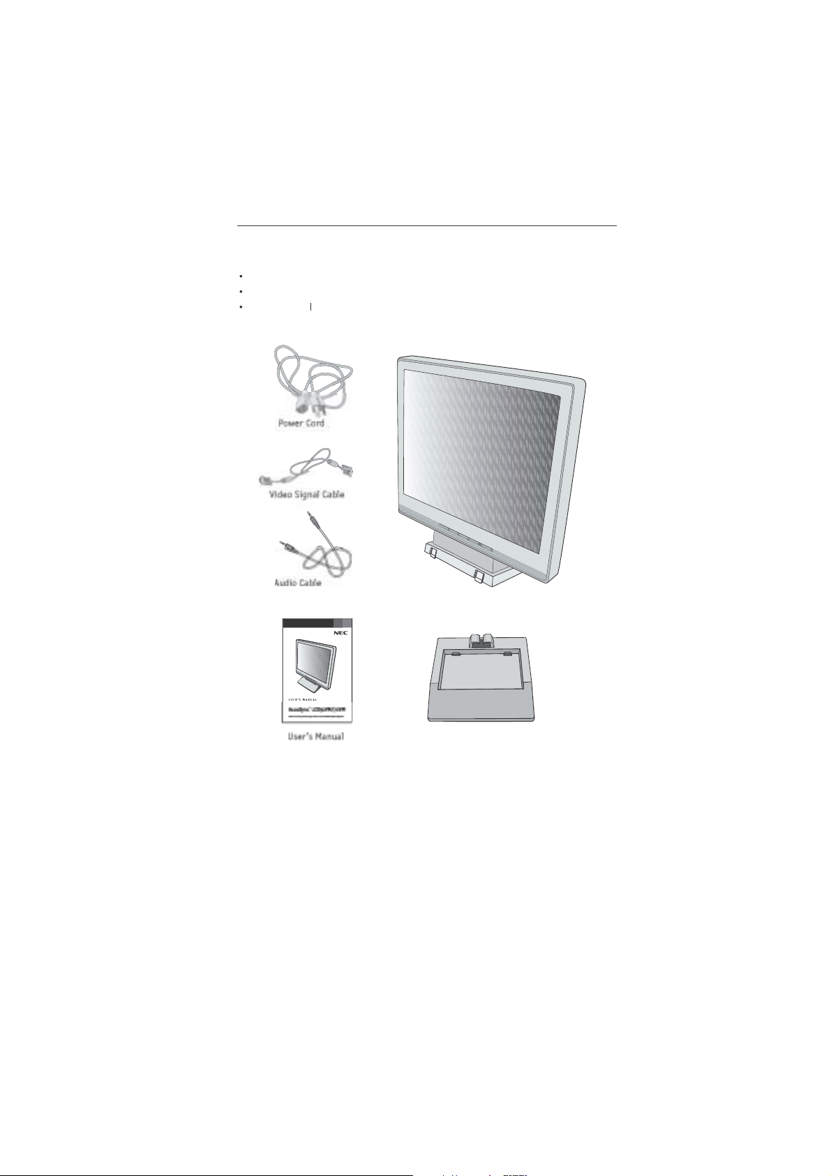
Your new NEC AccuSync LCD monitor box* should contain t
ollowing:
AccuSync LCD monitor with tilt base • Audio Ca
er Cor
User’s Manu
ccuSync LCD monitor (base stand not connected
• Video Signal Ca
• Base stan
aseStan
emember to save your original box and packing material to transport or ship the monitor.
1-4
Quick Star
t
To
d:
.
h
.
To
:
.
gp
.
n
r
.
s
.
r
n
.
“
”. While the headphones are connected, the sound from the speakers will
ypp
.
.
)
.
e
.
)
l
M
®
controls:
t
t
e
.
®
95/98/Me/2000/XP INF file for your AccuSync
.
.
bs
e
d
e
attach the Base to the LCD Stan
1. Insert the front of the LCD Stand into the holes in the front of the Base
2. Next, position the locking tabs on the back side of the LCD Stand with the holes on the
Base. Lower t
attach the AccuSync LCD monitor to your system, follow these instructions
1. Turn off the power to your computer
e Stand until locking tabs are secure
Stan
1
Locking Ta
as
nt Bas
connector of the display card in your system
For the MAC: Connect the AccuSync Macintosh cable adapter to the computer, the
attach the 15-pin mini D-SUB signal cable to the AccuSync Macintosh cable adapte
Figure A.2). Tighten all screws
NOTE: To obtain the AccuSync Macintosh cable adapter, call NEC-Mitsubishi Electronic
Display of America, Inc. at (800) 632-4662
3. Connect the 15-pin mini D-SUB of the video signal cable to the appropriate connecto
on the back of the monitor
the back of the monitor and the other end to the “Audio out” terminal of the computer
monitor
be disabled. Headphones can be purchased from your local electronics store
4. Connect one end of the power cord to the LCD and the other end to the power outlet
Place the video signal cable and power cord between the cable holder
NOTE: Adjust the position of cables between the holder to avoid damage
NOTE: If you use this monitor at AC125-240V, please refer to Recommended Us
section of this manual for proper selection of power cord
5. Turn on the monitor with the front power button and the computer.
6. No-touch Auto Adjust automatically adjusts the monitor to optimal settings upon initia
setup for most timings. For further adjustments, use the following OS
• Auto Adjust Contras
• Auto Adjus
Refer to the Controls section of this User’s Manual for a full description of thes
OSM controls
TE:For download information on the Windows
monitor, refer to the References section of this User’s Manual
TE:If you have any problems, please refer to theTroubleshooting section of this User’s Manual
Figure B.1). Connect the audio cable to AUDIO-INPUT o
Figure A.1). Tighten all screws
Figure B.1
Figure C.1
1-5
4
Quick Start
d
a
MacintoshCable Adapter
yqq
1
1
2
ble
r
pp
1
b)
holder
eadoe
n
Figure A.
igure B.
–continue
Macintosh Ca
Adapte
systems do not require
Figure A.
u
Figure C.
Power butto
1-6
lt
s
1
g
:
.
)
)
he
)
.
)
d.
d.
d.
Quick Start
d
1
2
1
e
e
3
–continue
Ti
Grasp both sides of the monitor screen with your hand
and adjust the tilt as desired (Figure TS.
Figure TS.
Remove Monitor Stand for Mountin
To prepare the monitor for alternate mounting purposes
1.Disconnect all cables
2.Place monitor face down on a nonabrasive surface (Figure R.1
3.Remove the 2 screws on the stand and lift off the stand
Figure R.1
4.Remove the 4 screws connecting the monitor to the stand and remove t
metal plate
Figure R.2
The monitor is now ready for mounting in an alternate manner
Connect the AC cord and signal cable to the back of the monitor
6. Reverse this process to reattach stan
NOTE: Use only VESA-compatible alternative mounting metho
TE:Handle with care when removing monitor stan
igure R.
non-abrasiv
surfac
Figure R.3
Figure R.
Figure R.
1-7
Quick Start
d
e
.
e
)
bs
k.
.
m
d
.
h
.
.
s
s
.
)
.
)
m
)
)
)
)
)
W
eight of LCD assembly:
)
)
–continue
Removing the Bas
Note: Always remove the Base when shipping the LCD
Place monitor face down on a non-abrasiv
surface (Figure R.1
2. While using your thumbs, press the bottom ta
upward to unloc
3. Press the top tabs down to unlock and pull off the stand
Connecting a Flexible Ar
This LCD monitor is designed for use with a flexible arm. Please use the attache
screws (4pcs) as shown in the picture when installing
To meet the safety requirements, the monitor must be mounted to an arm whic
guaranties the necessary stability under consideration of the weight of the monitor
The LCD monitor should only be used with an approved arm (e.g. GS mark)
Replace screw
Thickness of Bracket (Arm
.0~3.2 m
ighten all screws
5 mm (LCD51VM
100 mm (LCD71VM
Specification
4-SCREWS (M4
(MAX depth: 8.5 mm
75 mm (LCD51VM
100 mm (LCD71VM
If using other screws, check depth of holes
2.6 kg - LCD51VM (MAX
4.0 kg -LCD71VM (MAX
1-8
ontro
ls
OSM
®
(On-Screen Manager) control buttons on the front of the
:
E
E
d
Shortcut to bright
adjust window
g
f
e
w
OSM On
n
)
M
o
e
ft
C
OSM On
t
)
M
n
e
Adjust value
d
r
j
Cursor for adjust
ft
Adjust value
r
j
Cursor for adjust
ht
n
ff/
e
w
CT
–
+
AU
TO
n
OSM S
e
)
)
s
”
y
s
”
y
“–“ or “ +”
–
“
g
”.
)
(j)
)
y
”
y
s
”
“
g
”.
y
y
monitor function as follows
1. Basic key functio
utton
OSM Of
(Icon selectio
stage
(Adjustmen
stage
.
res
ELECT
e
SELE
OSM displaye
oves t
Adjustment stag
oves to Ico
selection stag
tructur
Main Menu (Icon Select
Cursor moves le
ecrease o
moves le
Shortcut to volum
adjust windo
ursor moves
ncrease o
moves rig
Main Menu (Adjust
res
ELECT
e
Press “SELECT” ke
/ RESET
Reset operatio
Mute o
on Volum
adjustment windo
VOLUM
UT
%
Adjust by usin
–“ or “ +
Press “SELECT
e
Sub Menu (Icon Select
ress
Sub Menu (Adjust
res
–“ or “ +
ress “SELECT” ke
Adjust by usin
–“ or “ +
1-9
ontrols
d
A
O
To mute the speaker sound, press the AUTO/RESET key.
pppp
SS
.
CONTRAST
d.
AUTO CONTRAST
.
AUTO A
ST
.
T
.
P
.
E
.
NE
p
COLOR CONTROL SYSTEMS
r
.
COLO
D
.
COLOR G
N
.
COLO
E
.
OOL
.
ACTORY PRESET
gy y g
gy y g
yg
yg
.
gg
gg
UDI
Control the sound volume of speakers and headphone.
BRIGHTNE
Adjusts the overall image and background screen brightness
Adjusts the image brightness in relation to the backgroun
Adjusts the image displayed for non-standard video inputs
Automatically adjusts the Image Position, the H. Size and Fine setting
LEFT/RIGH
Controls Horizontal Image Position within the display area of the LCD
DOWN/U
Controls Vertical Image Position within the display area of the LCD
H. SIZ
Adjusts the horizontal size by increasing or decreasing this setting
FI
Four color presets (9300/7500/6500/USER) select the desired colo
setting
Increase or decreases Red. The change will appear on screen
Increase or decreases Green. The change will appear on screen
Increase or decreases Blue. The change will appear on screen
T
Selecting TOOL allows you to get into the sub menu
–continue
DJU
R RE
REE
R BLU
ighlighting the control to be reset and pressing the RESET button
1-10
ontrols
d
OSM
®
Warning:
.
GNAL:
This function gives a warning when there is no signal present.
gg
gppgpp
After power is turned on or when there is a change of input signal or video
gg gpgg gp
he
p
l
window will appear.
:
This function gives a warning of use with
pp
optimized resolution. After power is turned on or when there is a change
gg
gg
of input signal or the video signal doesn’t have proper resolution, the
pp g
pp g
r
pg
pg
n
gpp
gpp
.
O
ANGE:
d
gpgp
of input signal or the video signal doesn’t have proper timing, the
pp
Out Of
g
e
.
g
.
ANGUAGE
.
OSM
F
The OSM control menu will stay on as long as it is in use. In the OSM
Tu
OFF submenu, you can select how long the monitor waits after
yg
yg
yg
yg
.
OSM LOCK OUT
s
without Brightness and Contrast. When attempting to activate OSM
pypy
gpg
gpg
pp g
pp
-
p
p
yy
yy
.
R
0
gpp
gpp
MONITO
O
–continue
Selecting EXIT allows you exit OSM menu/sub menu
L
OSM control menus are available in seven languages
TURN OF
choices are 10 - 120 seconds in 5 second intervals
This control completely locks out access to all OSM control function
“AUTO/ RESET“, then “+“ key and hold down simultaneously. To de
old down simultaneously
RESOLUTION NOTIFIE
If ON is selected, a message will appear on the screen after 3
R INF
Indicates the model and serial numbers of your monitor.
SI
is inactive, t
RESOLUTION NOTIFIER
Resolution Notifie
the TOOL menu
UT OF R
ang
menu will appear
OSM Warning menus disappear with SELECT button
No Signa
window will open. This function can be disabled i
This function gives a recommendation of the optimize
1-11
0
commended Us
e
e
E
N
:
MONITO
r
o
.
.
e
.
.
,
.
r
r
r
)
e
.
.
.
.
e
:
d.
.
.
.
.
d.
.
.
.
.
o
t
.
e
.
.
e
e
s
.
To
.
r
.
a
n
.
ON
Safety Precautions and Maintenanc
FOR OPTIMUM PERFORMANCE, PLEASE NOTE TH
FOLLOWING WHEN SETTING UP AND USING
THE ACCUSY
DO NOT OPEN THE
removing covers may expose you to dangerous shock hazards or other risks. Refer all servicing t
qualified service personnel
Do not spill any liquids into the cabinet or use your monitor near water
Do not insert objects of any kind into the cabinet slots, as they may touch dangerous voltag
points, which can be harmful or fatal or may cause electric shock, fire or equipment failure
Do not place any heavy objects on the power cord. Damage to the cord may cause shock or fire
Do not place this product on a sloping or unstable cart, stand or table, as the monitor may fall
causing serious damage to the monitor
When operating the AccuSync LCD monitor with its AC 125-240V power supply, use a powe
supply cord that matches the power supply voltage of the AC power outlet being used. The powe
supply cord you use must have been approved by and comply with the safety standards of you
country. (Type H05VV-F should be used in Europe
In UK, use a BS-approved power cord with molded plug having a black (5A) fuse installed for us
with this monitor. If a power cord is not supplied with this monitor, please contact your supplier
Do not place any objects onto the monitor and do not use the monitor outdoors
The inside of the fluorescent tube located within the LCD monitor contains mercury
Please follow the bylaws or rules of your municipality to dispose of the tube properly
Immediately unplug your monitor from the wall outlet and refer servicing to qualified servic
personnel under the following conditions
When the power supply cord or plug is damage
If liquid has been spilled, or objects have fallen into the monitor
If the monitor has been exposed to rain or water
If the monitor has been dropped or the cabinet damaged
If the monitor does not operate normally by following operating instructions
Do not bend power cor
Do not use monitor in high temperature, humid, dusty, or oily areas
If glass is broken, handle with care
o not cover vent on monitor
If monitor or glass is broken, do not come in contact with the liquid crystal and handle with care
Allow adequate ventilation around the monitor so that heat can properly dissipate. D
not block ventilated openings or place the monitor near a radiator or other hea
sources. Do not put anything on top of monitor
The power cable connector is the primary means of detaching the system from th
AUTI
Image Persistenc
Image persistence is when a residual or “ghost” image of a previous image remains visible on th
screen. Unlike CRT monitors, LCD monitors’ image persistence is not permanent, but constant image
being displayed for a long period of time should be avoided
alleviate image persistence, turn off the monitor for as long as the previous image was displayed
For example, if an image was on the monitor for one hour and a residual image remains, the monito
should be turned off for one hour to erase the image
moving screen saver at regular intervals whenever the screen is idle or turning off the monitor whe
not in use
power supply. The monitor should be installed close to a power outlet which is easily accessible
Handle with care when transporting. Save packaging for transporting
TE: As with all personal display devices, NEC-Mitsubishi Electronics Display recommends using
C LCD COLOR MONITOR
R. There are no user serviceable parts inside and opening o
1
1-12
commended Use
d
N
N
:
r
w
.
lightly bel
s
he
.
f
h
.
n
o
o
l
!
.
r
d
.
f
.
s
:
ls
g
z
d
t
e
l
.
.
CORRECT PLACEMENT AND ADJUSTMENT OF THE MONITOR
REDUCE EYE, SHOULDER AND NECK FATIGUE. CHECK THE
CA
FOLLOWI
For optimum performance, allow 20 minutes fo
arm-up
Adjust the monitor height so that the top of the
screen is at or s
should look slightly downward when viewing t
middle of the screen
Position your monitor no closer than 16 inches
urther away than 28 inches from your
and no
eyes. T
e optimal distance is 20 inches
Rest your eyes periodically by focusing on a
object at least 20 feet away. Blink often.
Position the monitor at a 90
minimize glare and reflections. Adjust the monitor tilt so that ceiling lights d
not reflect on your screen.
If reflected light makes it hard for you to see your screen, use an antiglare filter.
Clean the LCD monitor surface with a lint-free, nonabrasive cloth. Avoid using
eaning solution or glass cleaner
any c
Adjust the monitor’s brightness and contrast controls to enhance readability
Use a document holder placed close to the screen.
Position whatever you are looking at most of the time (the screen o
reference material) directly in front of you to minimize turning your hea
while you are typing
Avoid displaying fixed patterns on the monitor for long periods of time to avoid
image persistence (a
Get regular eye checkups
Ergonomic
To realize the maximum ergonomics benefits, we recommend the following
Use the preset Size and Position controls with standard signa
Use the preset Color Settin
Use non-interlaced signals with a vertical refresh rate between 60-75H
Do not use primary color blue on a dark background, as it is difficult to see an
may produce eye fatigue to insufficient contras
G WHEN YOU POSITION THE MONITOR
ow eye level. Your eye
angle to windows and other light sources t
terimage effects).
–continue
For more detailed information on setting up a healthy work environment, write th
American National Standard for Human Factors Engineering of Visual Display Termina
Workstations – ANSI-HFS Standard No. 100-1988 – The Human Factors Society, Inc
P.O. Box 1369, Santa Monica, California 90406
1-13
2
ifi
cation
s
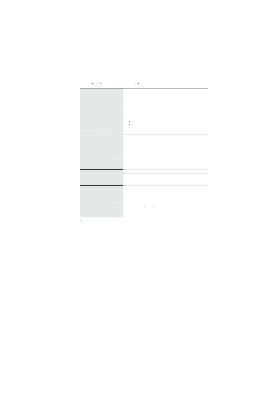
Monitor AccuSync LCD51VM Notes
ificati
Monitor
le
)
hl
t
d/m
2
;
l
l
s
)
e
e
s
d.
m
0Lef
)
s
0Up/
)
Sy
n
lly
R
e
lly
t
S
t
z
d.
600*
z
Hz
z
s
r
.
A
a
s
s
ly
0
0
V
z
t
s
g
A
s
)
)
ht
kg
lbs
s
5
O
95
%
0
000
t
0
S
40
%
t
i
ff
s
h
o
.
pec
LCD Modu
Input Signa
Display Color
Maximu
Viewing Angle
nchronizatio
ang
Resolutions Supported 720 x 400* :VGA tex
ctive Display Are
Power Supp
Speaker Practical Audio Outpu
Current Ratin
Dimension
Weig
Environmental Consideration
Interpolated Resolutions: When resolutions are shown that are lower than the pixel count of the LCD module, text may appear d
normal and necessary for all current flat panel technologies when displaying nonnative resolutions full screen. In flat panel technologies, eac
dot on the screen is actually one pixel, so to expand resolutions to full screen, an interpolation of the resolution must be d
NOTE: Technical specifications are subject to change without notice
ons
15.0 inch Active matrix; thin film transistor (TFT
Diagonal:
Viewable Image Size:
Native Resolution (Pixel Count):
Analog input:
Horizontal:
Horizontal :304.1 mm/12.0 inche
perating Temperature:C to 35C/41F to
torage Temperature:C to 60C/14F to 1
15.0 inc
1024 x 768 pitch; 250c
ANALOG 0.7 Vp-p/75 Ohm
Video:
Separate sync TTL Level (Positive/Negative
Sync:
Horizontal sync Positive/Negativ
Vertical sync Positive/Negativ
16,777,216 Depending on display card use
6
t/right:/60 (CR>10
4
Down:/60 (CR>10
31.5 kHz to 60 kHz Automatica
56 Hz to 75 Hz Automatica
Vertical:
640 x 480* at 60 Hz to 75 H
x
832 x 624* at 75
1024 x 768 at 60 Hz to 75 H
Vertical :228.1 mm/9.0 inche
1
-240
1 + 1 Watt
0.45 - 0.25
347.4 mm (W) x 341.9 mm (H) x 183.5 mm (D
13.7 inches (W) x 13.5 inches (H) x 7.2 inches (D
3.0
6.6
30% to 80
Humidity:
Humidity:
Feet:
Feet:
to 12,
-1
10% to 85
0 to 40,000 Fee
at 56 Hz to 75 H
50/60 H
Fee
iquid crystal display (LCD); 0.297 mm do
450:1 contrast ratio, typica
all modes liste
NEC-Mitsubishi Electronics Display cite
recommended resolution at 75 Hz fo
optimal display performance
white luminence
ome systems may not suppor
erent. This i
1
1-14
3
ifi
cations
d
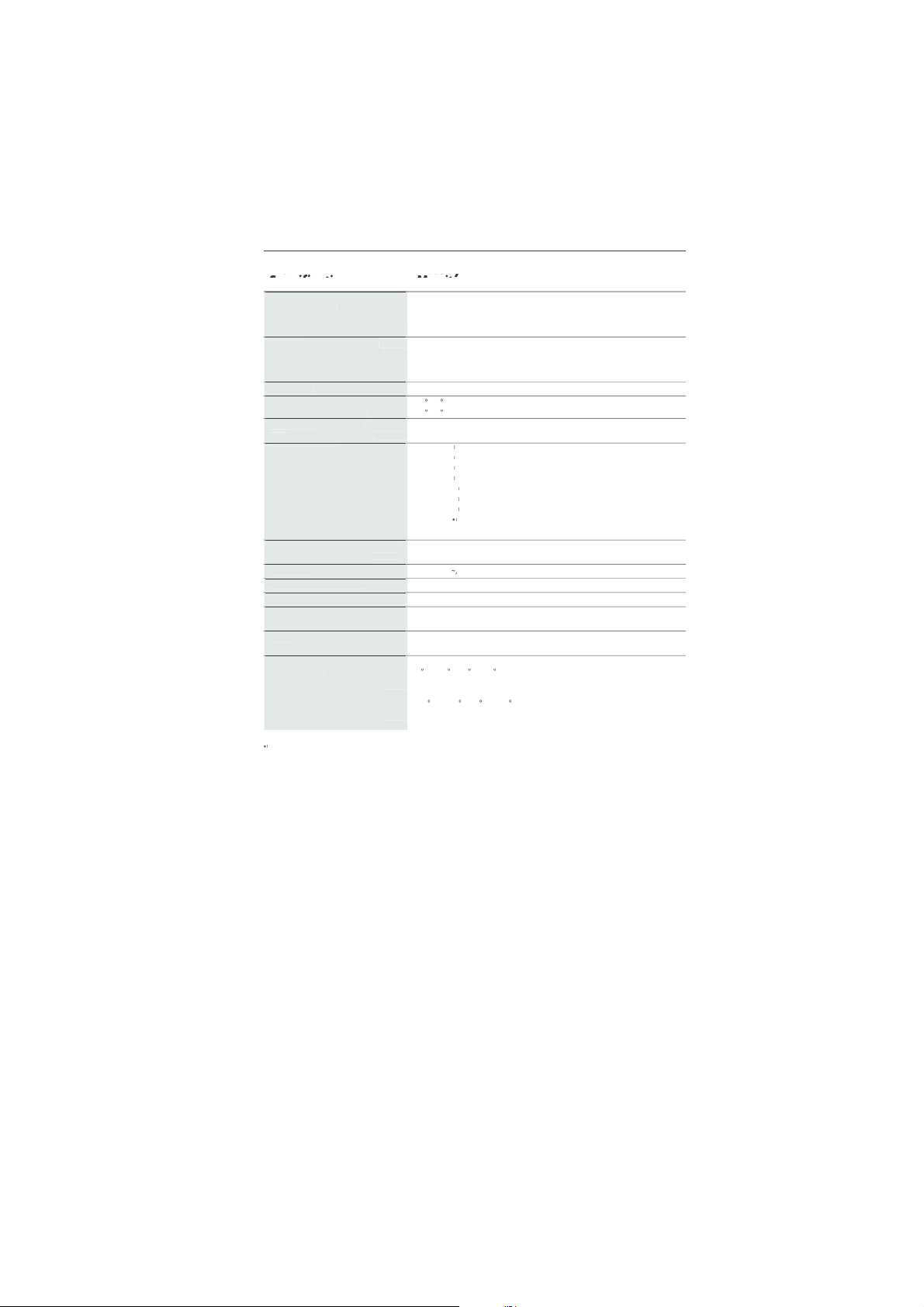
Monitor AccuSync LCD71VM Notes
ificati
Monitor
le
)
hl
t
d/m
2
;
l
l
s
)
e
e
s
d.
m
0Lef
)
s
0Up/
)
Sy
n
lly
R
e
lly
t
S
t
z
d.
600*
z
Hz
z
z
Hz
s
280
960
z
r
.
A
a
s
s
y
0
0
V
z
t
s
g
A
s
)
)
t
4.
6
kg
lbs
s
5
O
95
%
0
000
t
0
S
40
%
t
i
ff
s
h
o
.
–continue
pec
LCD Modu
Input Signa
Display Color
Maximu
Viewing Angle
nchronizatio
ang
Resolutions Supported 720 x 400* : VGA tex
ctive Display Are
Power Suppl
Speaker Practical Audio Outpu
Current Ratin
Dimension
Weigh
Environmental Consideration
Interpolated Resolutions: When resolutions are shown that are lower than the pixel count of the LCD module, text may appear d
normal and necessary for all current flat panel technologies when displaying non-native resolutions full screen. In flat panel technologies, eac
dot on the screen is actually one pixel, so to expand resolutions to full screen, an interpolation of the resolution must be d
NOTE: Technical specifications are subject to change without notice
ons
17.0 inch Active matrix; thin film transistor (TFT
Diagonal:
Viewable Image Size:
Native Resolution (Pixel Count):
Analog input:
Horizontal:
Horizontal :338 mm/13.3 inche
perating Temperature:C to 35C/41F to
torage Temperature:C to +60C/14F to 1
17.0 inc
1280 x 1024 pitch; 250c
ANALOG 0.7 Vp-p/75 Ohm
Video:
Separate sync TTL Level (Positive/Negative
Sync:
Horizontal sync Positive/Negativ
Vertical sync Positive/Negativ
16,194,277 Depending on display card use
7
t/right:/70 (CR>10
6
Down:/60 (CR>10
31.5 kHz to 81.1 kHz Automatica
56 Hz to 75 Hz Automatica
Vertical:
640 x 480* at 60 Hz to 75 H
x
832 x 624* at 75
1024 x 768* at 60 Hz to 75 H
1152 x 864* at 70 Hz to 75 H
1152 x 870* at 75
1
x
1280 x 1024 at 60 Hz to 75 Hz................optimal display performance
Vertical :270.3 mm/10.6 inche
1
-240
1 + 1 Watt
0.75 - 0.4
379 mm (W) x 383 mm (H) x 193 mm (D
14.9 inches (W) x 15.1 inches (H) x 7.6 inches (D
10.2
30% to 80
Humidity:
Humidity:
Feet:
Feet:
to 12,
-1
10% to 85
0 to 40,000 Fee
at 56 Hz to 75 H
at 60 Hz to 75 H
50/60 H
Fee
iquid crystal display (LCD); 0.264 mm do
450:1 contrast ratio, typica
all modes liste
NEC-Mitsubishi Electronics Display cite
recommended resolution at 60 Hz fo
white luminence
ome systems may not suppor
erent. This i
1
1-15

4
eature
s
f
t
.
r
®
Control Systems
e
.
OSM
®
s
.
l
.
n
®
,
k
d
s
:
The Microsoft
®
s
®
-
s
lly
.
M
®
(Intelligent Power Manager) System:
t
,
r
.
s
.
n
®
f
.
o
e
.
by
.
Reduced Footprint: Provides the ideal solution for environments requiring superior image
quality but with size and weight limitations. The monitor’s small
allow it to be moved or transported easily from one location to another
AccuColo
the color accuracy of your monitor to a variety of standards
(On-Screen Manager) Controls: Allow you to quickly and easily adjust all element
of your screen image via simple to use on-screen menus
No-touch Auto Adjust: No-touch Auto Adjust automatically adjusts the monitor to optima
settings upon initial setup
ErgoDesig
protect the health of the user and save money. Examples include
and easy image adjustments, tilt base for preferred angle of vision, small footprint an
compliance with MPRII and TCO guidelines for lower emission
Plug and Play
ng system facilitates setup and installation by allowing
(such as screen size and resolutions supported) directly to your computer, automatica
optimizing display performance
IP
allow the monitor to shift to a lower power consumption level when on but not in use
saving two-thirds of your monitor energy costs, reducing emissions and lowering the ai
conditioning costs of the workplace
Multiple Frequency Technology: Automatically adjusts monitor to the display card’
scanning frequency, thus displaying the resolution required
FullSca
signi
VESA Standard Mounting Interface: Allows users to connect their AccuSync monitor t
any VESA standard third party mounting arm or bracket. Allows for the monitor to b
mounted on a wall or an arm using any third party compliant device
Features: Enhance human ergonomics to improve the working environment
Capability: Allows you to use the entire screen area in most resolutions,
icantly expanding image size
: Allows you to adjust the colors on your screen and customiz
solution with the Window
Provides innovative power-saving methods tha
ootprint and low weigh
OSM controls for quic
95/98/Me/2000/XP operat
the monitor to send its capabilitie
OSM Display Screen Copyright 2003
NEC-Mitsubishi Electronics Display of America, Inc
1
1-16

No pictur
e
.
.
m
)
-
.
.
d
.
e
e
t
.
To
s
l
.
y
s
.
t
.
r
d
e
d.
y
.
.
t
)
d.
ly
.
m
)
o
.
.
d
.
.
.
The signal cable should be completely connected to the display card/computer
The display card should be completely seated in its slot
Front Power Switch and computer power switch should be in the ON position.
Check to make sure that a supported mode has been selected on the display card or syste
eing used. (Please consult display card or system manual to change graphics mode.
Check the monitor and your display card with respect to compatibility and recom
mended settings
Check the signal cable connector for bent or pushed-in pins
Power Button does not respon
• Unplug the power cord of the monitor from the AC outlet to turn off and reset the monitor
Image Persistenc
Image persistence is when a residual or “ghost” image of a previous image remains visibl
on the screen. Unlike CRT monitors, LCD monitors’ image persistence is not permanent, bu
constant images being displayed for a long period of time should be avoided
alleviate image persistence, turn off the monitor for as long as the previous image wa
displayed. For example, if an image was on the monitor for one hour and a residua
image remains, the monitor should be turned off for one hour to erase the image
TE: As with all personal display devices, NEC-Mitsubishi Electronics Displa
recommends using a moving screen saver at regular intervals whenever the screen i
idle or turning off the monitor when not in use
Image is unstable, unfocused or swimming is apparen
Signal cable should be completely attached to the computer
Use the OSM Image Adjust controls to focus and adjust display by increasing o
ecreasing the FINE control. When the display mode is changed, the OSM Imag
Adjust settings may need to be readjuste
Check the monitor and your display card with respect to compatibilit
and recommended signal timings
If your text is garbled, change the video mode to non-interlace and use 60Hz refresh rate
LED on monitor is not li
Power Switch should be in the ON position and power cord should be connecte
Display image is not sized proper
Use the OSM Image Adjust controls to increase or decrease the H.SIZE
Check to make sure that a supported mode has been selected on the display card or syste
eing used. (Please consult display card or system manual to change graphics mode.
No Vide
If no video is present on the screen, turn the Power button off and on again
Make certain the computer is not in a power-saving mode (touch the keyboard or mouse)
No Soun
Check to see if speaker cable is properly connected
Check to see if mute is activated
Check to see if volume in OSM is set at minimum
(no green or amber color can be seen
1-17

6
Refer
e
2
4
h
l
/
m
t
h
/
fm
l
h
/
m
n
]
7
0
m
n
6
2
ls
h
m
h
/
n
s
®
t
NEC-Mitsubishi Monitor Customer Service & Support
Customer Service and Technical Support:800) 632-466
Fax:(800) 695-304
Parts and Accessories/Macintos
Cable Adapter: (888) NEC-MITS [888-632-6487]
Customer Service Po
Online Technical Suppor
Knowledge Base:
Customer Service & Technica
Support Email:
Sales and Product Informatio
Sales Information Line: (888) NEC-MITS [888-632-6487
Canadian Customers: (866) 771-0266, Ext#: 403
Government Sales: (800) 284-632
Government Sales email: gov@necmitsubishi.co
Rebate Status Informatio
NEC Rebate Status: www.rebatesHQ.com or 866-765-569
Mitsubishi Rebate Status: www.rebatesHQ.com or 877-405-469
icies & Processes:http://www.necmitsubishi.com
css/ServicePolicies/ServicePolicies.ht
ttp://www.necmitsubishi.com
css/knowledgebase.c
ttp://www.necmitsubishi.com
css/techform.ht
Electronic Channe
World Wide Web:
Product Registration:
European Operations: http://www.nec-mitsubishi.com
Window
95/98/Me/2000/XP INF File:ttp://www.necmitsubishi.com and selec
ttp://www.necmitsubishi.co
ttp://www.necmitsubishi.com
productregistratio
“Drivers and Downloads”
1
1-18

Limited Warrant
y
s
t
t
w
.
r
.
y
t
a
d
he
by
e
w
e
e
.
r
d
a
r
e
a
t
t
g
o
.
,
T
L
E
.
E
-
.
s
e
e
l
t
d
.
,
.
NEC-Mitsubishi Electronics Display of America, Inc. (hereinafter “NMD-A”) warrants thi
Product to be free from defects in material and workmanship and, subject to the conditions se
orth below, agrees to repair or replace (at NMD-A’s sole option) any part of the enclosed uni
hich proves defective for a period of three (3) years from the date of first consumer purchase
Spare parts are warranted for ninety (90) days. Replacement parts or unit may be new o
refurbished and will meet specifications of the original parts or unit
This warranty gives you specific legal rights and you may also have other rights, which var
rom state to state. This warranty is limited to the original purchaser of the Product and is no
transferable. This warranty covers only NMD-A-supplied components. Service required as
result of third party components is not covered under this warranty. In order to be covere
under this warranty, the Product must have been purchased in the U.S.A. or Canada by t
original purchaser. This warranty only covers Product distribution in the U.S.A. or Canada
NMD-A No warranty service is provided outside of the U.S.A. or Canada. Proof of Purchas
ill be required by NMD-A to substantiate date of purchase. Such proof of purchase must b
an original bill of sale or receipt containing name and address of seller, purchaser, and th
serial number of the product
It shall be your obligation and expense to have the Product shipped, freight prepaid, o
delivered to the authorized reseller from whom it was purchased or other facility authorize
y NMD-A to render the services provided hereunder in either the original package or
similar package affording an equal degree of protection. All Products returned to NMD-A fo
service MUST have prior approval, which may be obtained by calling 1-800-632-4662. Th
Product shall not have been previously altered, repaired, or serviced by anyone other than
service facility authorized by NMD-A to render such service, the serial number of the produc
shall not have been altered or removed. In order to be covered by this warranty the Produc
shall not have been subjected to displaying of fixed images for long periods of time resultin
in image persistence (afterimage effects), accident, misuse or abuse or operated contrary t
the instructions contained in the User’s Manual. Any such conditions will void this warranty
MD-A SHALL NOT BE LIABLE FOR DIRECT, INDIRECT, INCIDENTAL, CONSEQUENTIAL
OR OTHER TYPES OF DAMAGES RESULTING FROM THE USE OF ANY NMD-A PRODUC
OTHER THAN THE LIABILITY STATED ABOVE. THESE WARRANTIES ARE IN LIEU OF AL
OTHER WARRANTIES EXPRESS OR IMPLIED, INCLUDING, BUT NOT LIMITED TO, TH
IMPLIED WARRANTIES OF MERCHANTABILITY OR FITNESS FOR A PARTICULAR PURPOSE
SOME STATES DO NOT ALLOW THE EXCLUSION OF IMPLIED WARRANTIES OR TH
LIMITATION OR EXCLUSION OF LIABILITY FOR INCIDENTAL OR CONSEQUENTIAL DAM
AGES SO THE ABOVE EXCLUSIONS OR LIMITATIONS MAY NOT APPLY TO YOU
This Product is warranted in accordance with the terms of this limited warranty. Consumer
are cautioned that Product performance is affected by system configuration, software, th
application, customer data, and operator control of the system, among other factors. Whil
NMD-A Products are considered to be compatible with many systems, specific functiona
implementation by the customers of the Product may vary. Therefore, suitability of a Produc
or a specific purpose or application must be determined by consumer and is not warrante
by NMD-A
For the name of your nearest authorized NEC-Mitsubishi Electronics Display service facility
contact NEC-Mitsubishi Electronics Display of America at 1-800-632-4662
1-19

8
TCO’9
9
d
d
e
f
.
?
-
s
l
n
t
.
e
.
e
o
y
.
?
d
t
a
t
.
f
.
,
r
n
s
,
r
.
n
.
s
s
,
f
e
e
-
Congratulations! You have just purchased a TCO’99 approved an
abelled product! Your choice has provided you with a product develope
or professional use. Your purchase has also contributed to reducing th
burden on the environment and also to the further development o
environmentally adapted electronics products
Why do we have environmentally labelled computers
In many countries, environmental labelling has become an established method for encourag
ing the adaptation of goods and services to the environment. The main problem, as far a
computers and other electronics equipment are concerned, is that environmentally harmfu
substances are used both in the products and during the manufacturing. Since it has not bee
possible for the majority of electronics equipment to be recycled in a satisfactory way, mos
of these potentially damaging substances sooner or later enter Nature
There are also other characteristics of a computer, such as energy consumption levels, that ar
important from the viewpoints of both the work (Internal) and natural (external) environments
Since all methods of conventional electricity generation have a negative effect on th
environment (acidic and climate-influencing emissions, radioactive waste, etc.), it is vital t
conserve energy. Electronics equipment in offices consume an enormous amount of energ
since they are often left running continuously
What does labelling involve
This product meets the requirements for the TCO’99 scheme which provides for international an
environmental labelling of personal computers. The labelling scheme was developed as a join
effort by the TCO (The Swedish Confederation of Professional Employees), Svensk
Naturskyddsforeningen (The Swedish Society for Nature Conservation) and Statens Energimyndighe
(The Swedish National Energy Administration)
The requirements cover a wide range of issues: environment, ergonomics, usability, emission o
electrical and magnetic fields, energy consumption and electrical and fire safety
The environmental demands concern restrictions on the presence and use of heavy metals
brominated and chlorinated flame retardants, CFCs (freons) and chlorinated solvents, among othe
things. The product must be prepared for recycling and the manufacturer is obliged to have a
environmental plan which must be adhered to in each country where the company implements it
operational policy. The energy requirements include a demand that the computer and/or display
after a certain period of inactivity, shall reduce its power consumption to a lower level in one o
more stages. The length of time to reactivate the computer shall be reasonable for the user
Labelled products must meet strict environmental demands, for example, in respect of the reductio
of electric and magnetic fields, physical and visual ergonomics and good usability
Environmental Requirement
Flame retardant
Flame retardants are present in printed circuit boards, cables, wires, casings and housings. In turn
they delay the spread of fire. Up to thirty percent of the plastic in a computer casing can consist o
lame retardant substances. Most flame retardants contain bromine or chloride and these ar
related to another group of environmental toxins, PCBs, which are suspected to give rise to sever
health effects, including reproductive damage in fisheating birds and mammals, due to the bio
1
1-20

9
TCO’99
d
r
.
n
n
.
*
e
.
.
*
r
d
.
e
.
M
m
.
o
.
CFCs
d
f
.
g
.
.
.
l
khol
N
f
h
/
accumulative* processes. Flame retardants have been found in human blood and researchers fea
that disturbances in foetus development may occur
TCO’99 demand requires that plastic components weighing more than 25 grams must not contai
lame retardants with organically bound chlorine and bromine. Flame retardants are allowed i
the printed circuit boards since no substitutes are available
–continue
Lead*
Lead can be found in picture tubes, display screens, solders and capacitors. Lead damages th
nervous system and in higher doses, causes lead poisoning
TCO’99 requirement permits the inclusion of lead since no replacement has yet been developed
Cadmium*
Cadmium is present in rechargeable batteries and in the color generating layers of certain compute
isplays. Cadmium damages the nervous system and is toxic in high doses
TCO’99 requirement states that batteries, the color generating layers of display screens and th
electrical or electronics components must not contain any cadmium
ercury**
Mercury is sometimes found in batteries, relays and switches, Mercury damages the nervous syste
and is toxic in high doses
TCO’99 requirement states that batteries may not contain any Mercury. It also demands that n
mercury is present in any of the electrical or electronics components associated with the display unit
(freons)
CFCs (freons) are sometimes used for washing printed circuit boards. CFCs break down ozone an
thereby damage the ozone layer in the stratosphere, causing increased reception on Earth o
ultraviolet light with consequent increased risks of skin cancer (malignant melanoma)
The relevant TCO’99 requirement; Neither CFCs nor HCFCs may be used during the manufacturin
and assembly of the product or its packaging
*Bio-accumulative is defined as substances which accumulate within living organisms
**Lead, Cadmium and Mercury are heavy metals which are Bio-accumulative
To obtain complete information on the environmental criteria document, order from:
TCO Deve
SE-114 94 Stoc
SWEDE
FAX Number: +46 8 782 92 07
-mail (Internet): development@tco.se
You may also obtain current in
visiting t
eir website at: http://www.tcodevelopment.com
opment Unit
m
ormation on TCO’99 approved and labelled products by
1
1-21
Declaration of the Manufacture
r
We
r
d
)
are
h
:
0
:
2
2
3
4
h
l
n
,
u
T
okyo 108-0023, Japan
hereby certify that the color monito
AccuSync™ LCD51VM (L152R5) an
AccuSync LCD71VM (L172R6
Council Directive 73/23/EEC
in compliance wit
EN 6095
Council Directive 89/336/EEC
and marked wit
EN 5502
EN 61000-3EN 61000-3EN 5502
NEC-Mitsubishi Electric Visua
ystems Corporatio
4-13-23, Shibaura
Minato-K
1-22
1
a
R
f
f
h
f
f
f
f
f
.
e
f
Y
f
y
f
dd
ll
8
0
r
del:
)
.
.
E
S
AR
a
s
A
Y
S
AR
®
Y
S
AR
Y
S
AR
emblem does not represent EPA endorsement of any product or service.
NEC LCD Series
The information disclosed in this document, including all designs and related materials, is the valuable property of NECMitsubishi Electronics Display o
proprietary rights to this document, including all design, manu
to t
The NEC-Mitsubishi Electronics Display o
with the terms o
such product is dependent upon
implementation by customers o
must be determined by the customer and is not warranted by NEC-Mitsubishi Electronics Display o
To allow for design and specification improvements, the information in this document is subject to change at any tim
without notice. Reproduction of this document or portions thereof without prior approval of NEC-Mitsubishi Electronics
Display o
PROPRIETARY NOTICE AND LIABILITY DISCLAIME
America and/or its licensors, as appropriate, reserve all patent, copyright and other
e extent said rights are expressly granted to others.
the Limited Warranty Statement accompanying each product. However, actual performance of each
America product(s) discussed in this document are warranted in accordance
actors such as system configuration, customer data and operator control. Since
each product may vary, the suitability of specific product configurations and applications
America is prohibited.
acturing, reproduction, use and sales rights thereto, except
America
DECLARATION OF CONFORMIT
This device complies with Part 15 of FCC Rules. Operation is subject to the following two conditions. (1) This device may
not cause harm
cause undesired operation.
Windows is a registered trademark of Microsoft Corporation. NEC is a registered trademark of NEC Corporation
U.S. registered trademark. All other brands and product names are trademarks or registered trademarks of their respective owner
s an
guidelines for energy efficiency. The
ul interference, and (2) this device must accept any interference received, including interference that ma
U.S. Responsible Party: NEC-Mitsubishi Electronics Display o
ress: 1250 North Arlington Heights Road, Suite 500
A
Tel. No.: (630) 467-300
Itasca, I
inois 60143-124
America, Inc.
Type of Product: Display Monito
Equipment Classification: Class B Peripheral
Mo
We hereby declare that the equipment specified above
conforms to the technical standards as specified in the FCC Rules
ERG
T
Partner, NEC-Mitsubishi Electronics Display of America has determined that this product meets the
ERG
AccuSync LCD51VM (L152R5) / LCD71VM (L172R6
T
T
ERG
s
T
Part No. 1550168
Printed in Chin
1-23

2. B Version
AccuSync LCD51VM
AccuSync LCD71VM
User’s Manual
1-24
WARNING
TO PREVENT FIRE OR SHOCK HAZARDS, DO NOT EXPOSE THIS UNIT TO RAIN OR MOISTURE. ALSO, DO NOT
USE THIS UNIT’S POLARIZED PLUG WITH AN EXTENSION CORD RECEPTACLE OR OTHER OUTLETS UNLESS
THE PRONGS CAN BE FULLY INSERTED.
REFRAIN FROM OPENING THE CABINET AS THERE ARE HIGH VOLTAGE COMPONENTS INSIDE. REFER
SERVICING TO QUALIFIED SERVICE PERSONNEL.
CAUTION
RISK OF ELECTRIC SHOCK • DO NOT OPEN
CAUTION: TO REDUCE THE RISK OF ELECTRIC SHOCK, DO NOT REMOVE COVER (OR BACK). NO USER
SERVICEABLE PARTS INSIDE. REFER SERVICING TO QUALIFIED SERVICE PERSONNEL.
This symbol warns user that uninsulated voltage within the unit may have sufficient magnitude to cause
electric shock. Therefore, it is dangerous to make any kind of contact with any part inside this unit.
This symbol alerts the user that important literature concerning the operation and maintenance of this unit
has been included. Therefore, it should be read carefully in order to avoid any problems.
Caution:
When operating the AccuSync LCD51VM/AccuSync LCD71VM with a 220-240V AC power source in Europe, use the power
cord provided with the monitor.
In the UK, a BS approved power cord with a moulded plug has a Black (five Amps) fuse installed for use with this equipment.
If a power cord is not supplied with this equipment please contact your supplier.
For all other cases, use a power cord that matches the AC voltage of the power outlet and has been approved by and
complies with the safety standard of your particular country.
English
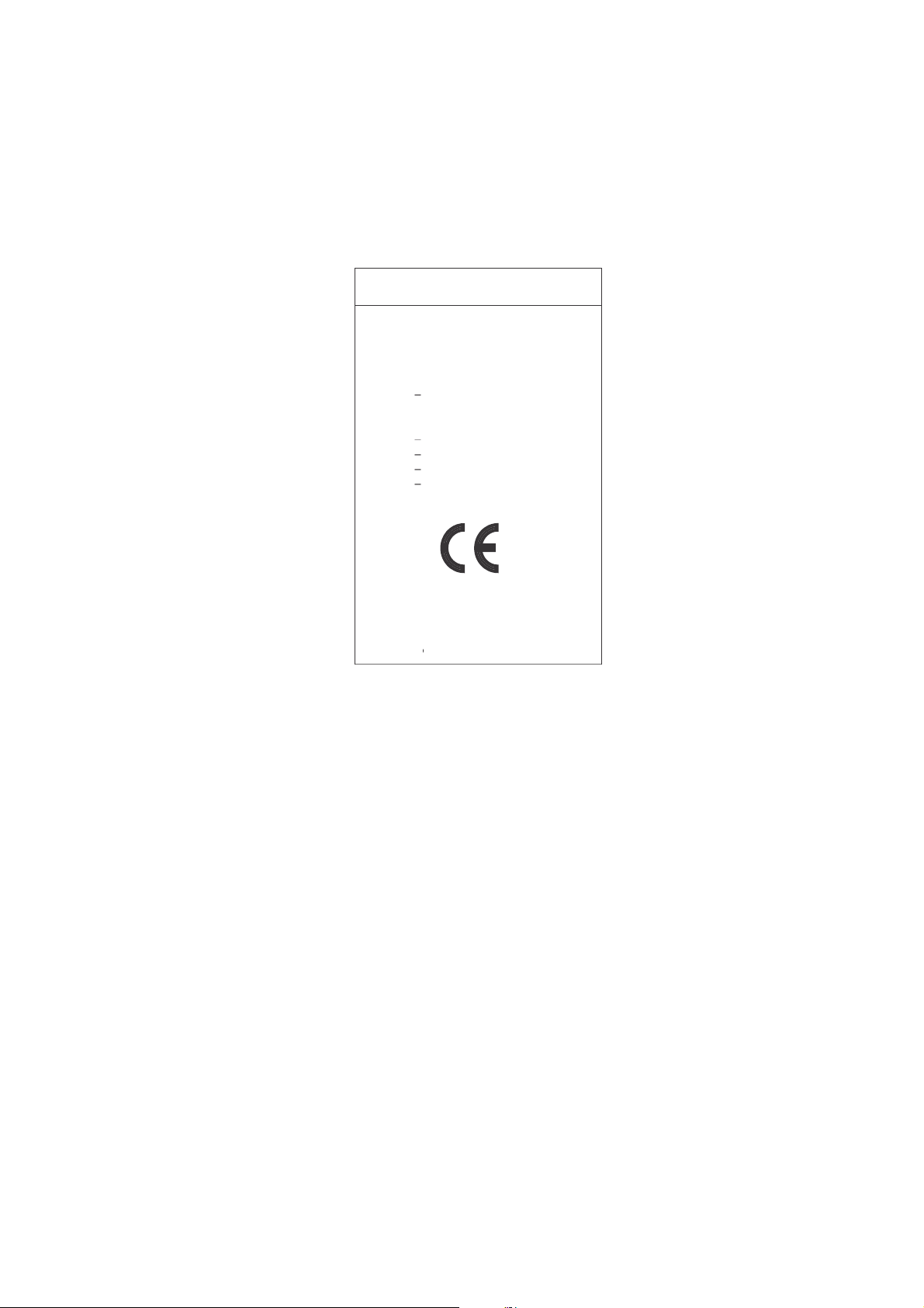
Declaration
Declaration of the Manufacturer
We hereby certify that the colour monitor
AccuSync LCD51VM/AccuSync LCD71VM
are in compliance with
Council Directive 73/23/EEC:
– EN 60950
Council Directive 89/336/EEC:
– EN 55022
– EN 61000-3-2
– EN 61000-3-3
– EN 55024
As an E
NERGY STAR
S
TAR
guidelines for energy efficiency. E
ErgoDesign is a registred trademark of NEC-Mitsubishi Electric Visual Systems Corporation in Austria, Benelux, Denmark,
France, Germany, Italy, Norway, Spain, Sweden, U.K..
IBM PC/XT/AT, PS/2, MCGA, VGA, 8514/A and XGA are registered trademarks of International Business Machines
Corporation.
Apple and Macintosh are registered trademarks of Apple Computer Inc.
Microsoft and Windows are registered trademarks of the Microsoft Corporation.
NEC is a registered trademark of NEC Corporation.
All other trademarks or registered trademarks are property of their respective owners.
Partner, NEC-Mitsubishi Electric Visual Systems Corp. has determined that this product meets the E
NERGY STAR
is a U.S. registered mark.
English-1
and marked with
NEC-Mitsubishi Electric Visual
Systems, Corp.
MS Shibaura Bldg., 13-23,
Shibaura 4-chome,
Minato-Ku, Tokyo 108-0023, Japan
NERGY
1-25
For the Customer to use in U.S.A. or Canada
Canadian Department of Communications Compliance Statement
DOC: This Class B digital apparatus meets all requirements of the Canadian Interference-Causing Equipment Regulations.
Cet appareil numérique de la classe B respecte toutes les exigences du Règlement sur le matériel brouiller du Canada.
C-UL: Bears the C-UL Mark and is in compliance with Canadian Safety Regulations according to CSA C22.2 No. 60950.
Ce produit porte la marque ‘C-UL’ et se conforme aux règlements de sûrele Canadiens selon CAN/CSA C22.2 No. 60950.
FCC Information
1. Use the attached specified cables with the AccuSync LCD51VM/AccuSync LCD71VM colour monitor so as not to
interfere with radio and television reception.
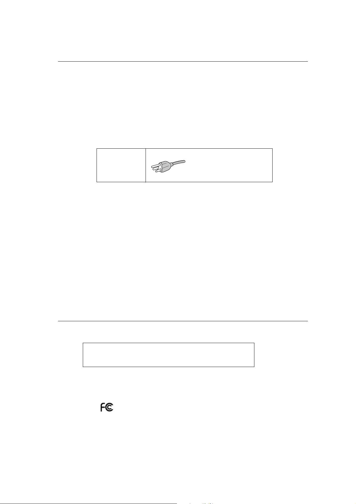
(1) The power supply cord you use must have been approved by and comply with the safety standards of U.S.A.,
and meet the following condition.
Power supply cord Non shield type, 3-conductor
Length 2.0 m
Plug shape
U.S.A
(2) Shielded video signal cable. Use of other cables and adapters may cause interference with radio and television
reception.
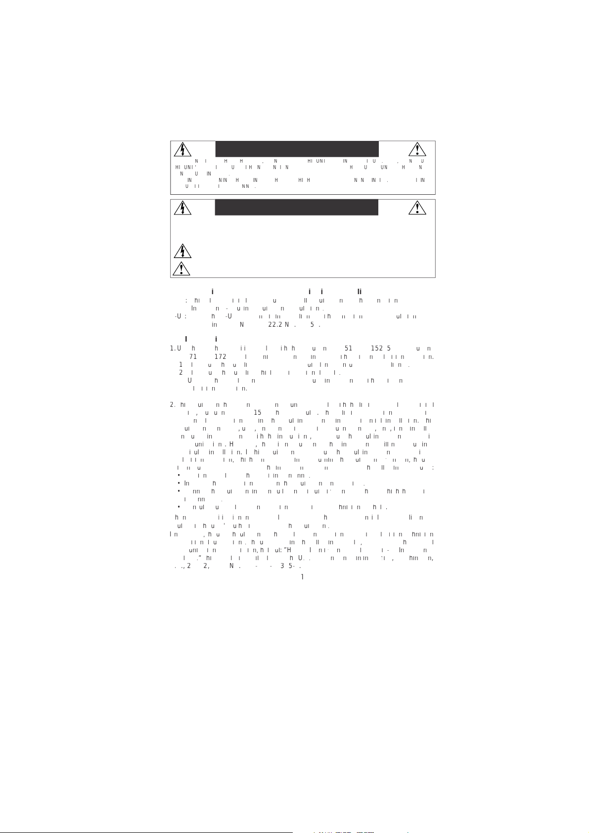
2. This equipment has been tested and found to comply with the limits for a Class B digital device, pursuant to part 15 of
the FCC Rules. These limits are designed to provide reasonable protection against harmful interference in a residential
installation. This equipment generates, uses, and can radiate radio frequency energy, and, if not installed and used in
accordance with the instructions, may cause harmful interference to radio communications. However, there is no
guarantee that interference will not occur in a particular installation. If this equipment does cause harmful interference
to radio or television reception, which can be determined by turning the equipment off and on, the user is encouraged
to try to correct the interference by one or more of the following measures:
• Reorient or relocate the receiving antenna.
• Increase the separation between the equipment and receiver.
• Connect the equipment into an outlet on a circuit different from that to which the receiver is connected.
• Consult your dealer or an experienced radio/TV technician for help.
If necessary, the user should contact the dealer or an experienced radio/television technician for additional
suggestions. The user may find the following booklet, prepared by the Federal Communications Commission, helpful:
“How to Identify and Resolve Radio-TV Interference Problems.” This booklet is available from the U.S. Government
Printing Office, Washington, D.C., 20402, Stock No. 004-000-00345-4.
Declaration of Conformity
This device complies with Part 15 of FCC Rules. Operation is subject to the following two conditions. (1) This device may not
cause harmful interference, and (2) this device must accept any interference received, including interference that may cause
undesired operation.
U.S. Responsible Party: NEC-Mitsubishi Electronics Display of America, Inc.
Address: 1250 N. Arlington Heights Road
Tel. No.: (630) 467-3000
Type of Product: Display Monitor
Equipment Classification: Class B Peripheral
Model: AccuSync LCD51VM/AccuSync LCD71VM
Itasca, Illinois 60143-1248
We hereby declare that the equipment specified above conforms
to the technical standards as specified in the FCC Rules.
English-2
1-26
Contents
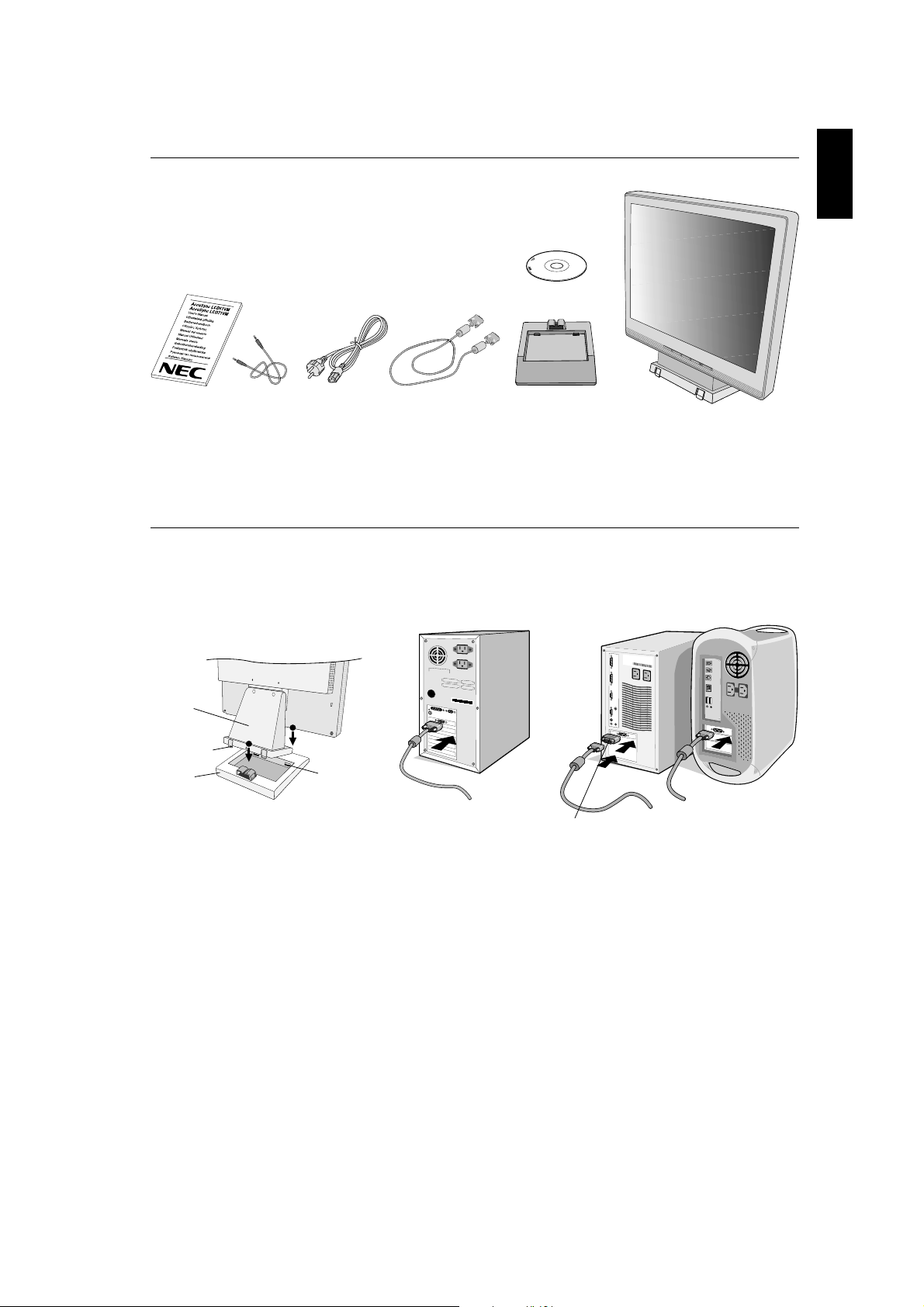
Your new NEC AccuSync LCD monitor box* should contain the following:
• AccuSync LCD monitor with tilt base
• Audio Cable
• Power Cord
• Video Signal Cable
• User’s Manual
• CD-ROM
English
CD-ROM
User’s Manual Audio Cable Power Cord
Remember to save your original box and packing material to transport or ship the monitor.
*
Video Signal Cable
Base Stand AccuSync LCD monitor
(base stand not connected)
Quick Start
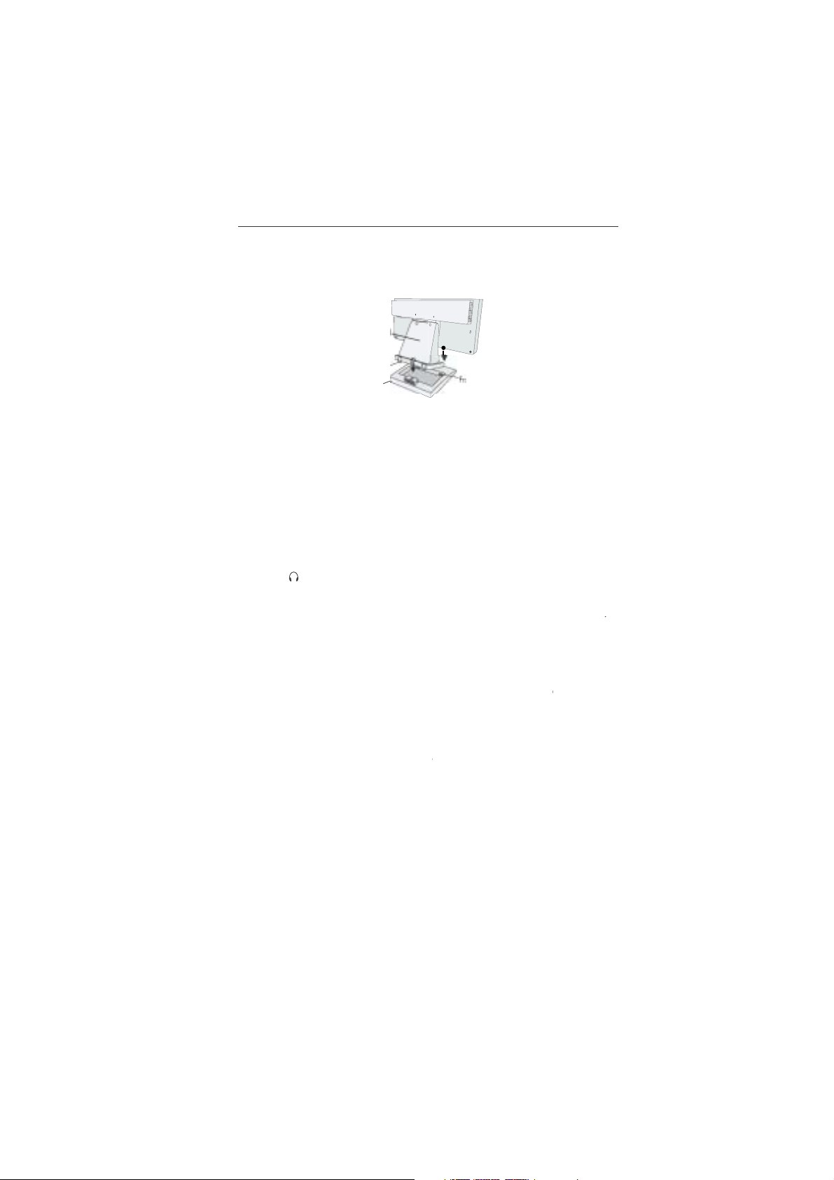
To attach the Base to the LCD Stand:
1. Insert the front of the LCD stand into the holes in the front of the Base (Figure S.1).
2. Next, position the locking tabs on the back side of the LCD stand with the holes on the Base. Lower the Stand in place until
locking tabs are secure (Figure S.1).
Stand
1
Locking Tabs
Base
2
Figure S.1
Front Base
Holes
Figure A.1
Macintosh Cable
Adapter (not included)
Figure A.2
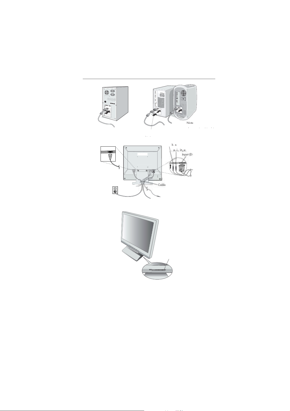
To attach the AccuSync LCD monitor to your system, follow these instructions:
1. Turn off the power to your computer.
2. For the PC with Analog output: Connect the 15-pin mini D-SUB signal cable to the connector of the display card in your
system (Figure A.1). Tighten all screws.
For the Mac: Connect the MultiSync Macintosh cable adapter (not included) to the computer. Attach the 15-pin
mini D-SUB signal cable to the MultiSync Macintosh cable adapter (Figure A.2). Tighten all screws.
NOTE: Some Macintosh systems do not require a Macintosh cable adapter.
English-3
1-27

3. Connect the 15-pin mini D-SUB of the video signal cable, Audio Cable and Headphone (not included) to the appropriate
connector on the back of the monitor (Figure B.1).
4. Connect one end of the power cord to the monitor and the other end to the power outlet. Place the Video Signal Cable,
Headphone (not included) and power cord to the Cable holder (Figure B.1).
NOTE: Adjust position of cable that place under the Cable holder to avoid damage for cable or monitor.
NOTE: If you use this monitor at AC125-240V, please refer to Recommended Use section of this manual for proper
5. Turn on the monitor with the front power button and the computer (Figure C.1).
selection of power cord.
HEAD PHONE
Connect to
Computer audio output
AUDIO INPUT
Input (D-Sub)
Power Button
Cable holder
Figure B.1
6. No-touch Auto Adjust automatically adjusts the monitor to optimal settings upon initial setup for most timings.
For further adjustments, use the following OSM controls:
• Auto Adjust Contrast
• Auto Adjust
Refer to the Controls section of this User’s Manual for a full description of these OSM controls.
NOTE: If you have any problem, please refer to the Troubleshooting section of this
User’s Manual.
Figure C.1
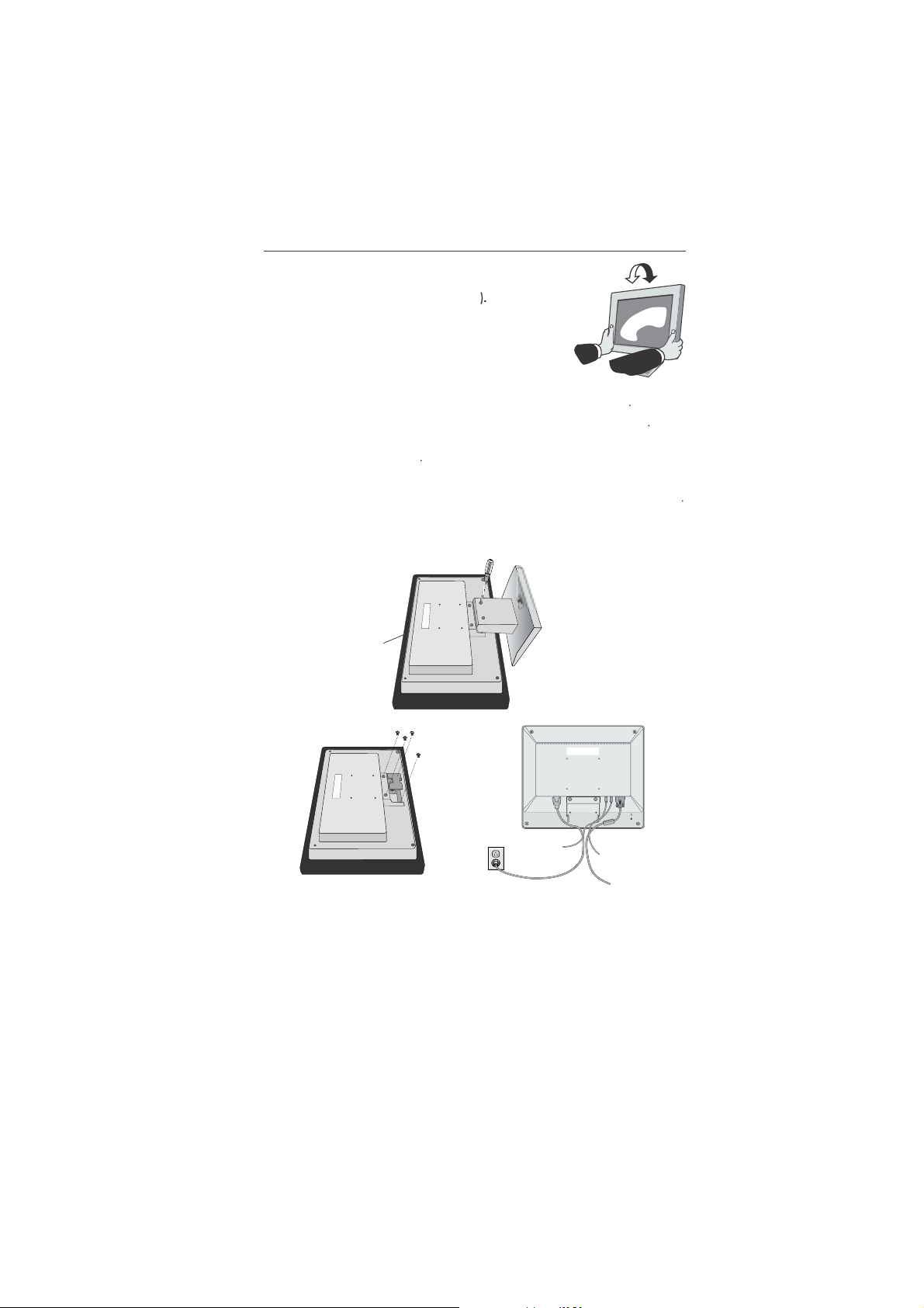
Tilt
Grasp both sides of the monitor screen with your hands and adjust the tilt as desired
(Figure TS.1).
Remove Monitor Stand for Mounting
To prepare the monitor for alternate mounting purposes:
1. Disconnect all cables.
2. Place monitor face down on a non-abrasive surface (Figure R.1).
3. Remove the 2 screws connecting the monitor to the stand and lift off the stand (Figure R.1)
4. Remove the 4 screws connecting the monitor to the stand and lift off the stand, assembly (Figure R.2).
The monitor is now ready for mounting in an alternate manner.
5. Connect the AC cord and signal cable to the back of the monitor (Figure R.3).
6. Reverse this process to reattach stand.
NOTE: Use only VESA-compatible alternative mounting method.
NOTE: Handle with care when removing monitor stand.
Figure TS.1
English-4
1-28

Non-abrasive surface
English
Figure R.1
Figure R.2 Figure R.3
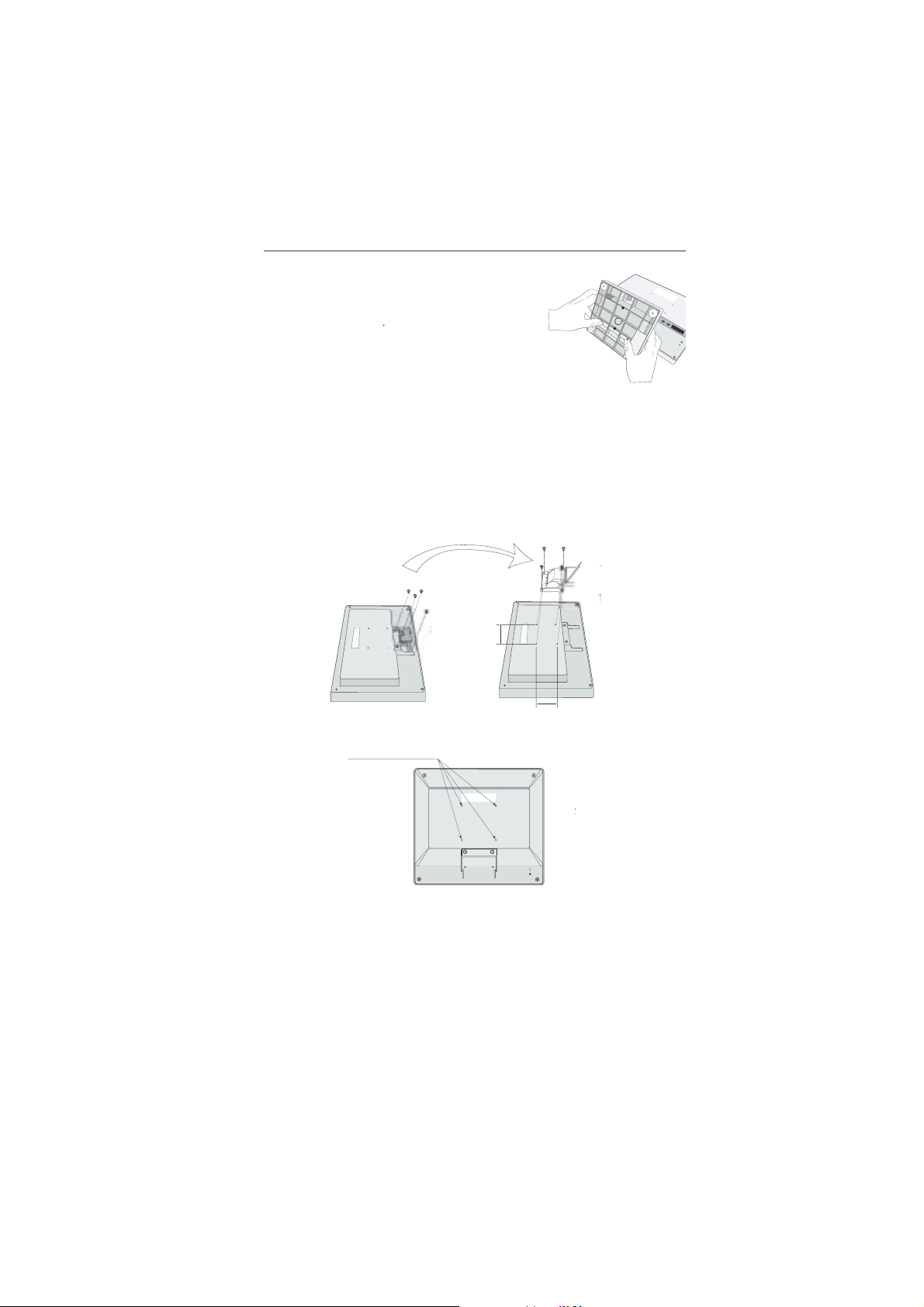
Removing the Base
NOTE: Always remove the Base when shipping the LCD.
1. Place monitor face down on a non-abrasive surface (Figure R.1).
2. While using your thumbs, press the bottom tabs upward to unlock.
3. Press the top tabs down to unlock and pull off the stand.
Connecting a Flexible Arm
This LCD monitor is designed for use with a flexible arm.
Please use the attached screws (4pcs) as show in the picture when installing. To meet the safety requirements, the monitor
must be mounted to an arm which guaranties the necessary stability under consideration of the weight of the monitor.
The LCD monitor shall only be used with an approved arm (e.g. GS mark).
Replace screws
Thickness of Bracket
(Arm) 2.0 ~ 3.2 mm
Tighten all screws
75 mm (LCD51VM)
100 mm (LCD71VM)
Specifications
4-SCREWS (M4)
(MAX depth: 8.5 mm)
If use other
screw, check
depth of hole.
75 mm (LCD51VM)
100 mm (LCD71VM)
Weight of LCD assembly: 2.6 kg - LCD51VM (MAX)
4.0 kg - LCD71VM (MAX)
English-5
1-29

Controls
OSM (On-Screen Manager) control buttons on the front of the monitor
function as follows:
1. Basic function at pressing each key
Button
At No OSD
showing
At OSD showing
(Icon selection stage)
At OSD showing
(Adjustment stage)
SELECT
Showing OSM.
Go to Adjustment stage. Cursor goes to left. Cursor goes to right.
Go to Icon selection stage. Adjust value decrease or
Shortcut to Bright adjust
window.
Cursor for adjust goes to left.
– +
Shortcut to Volume adjust
window.
Adjust value increase or
Cursor for adjust goes to
right.
AUTO / RESET
“Auto adjust” operate.
Reset operation.
Mute off/on switch on Volume
adjustment window.
NOTE: To quit the OSM screen at any time during the operation, press SELECT key for longer than 3 seconds.
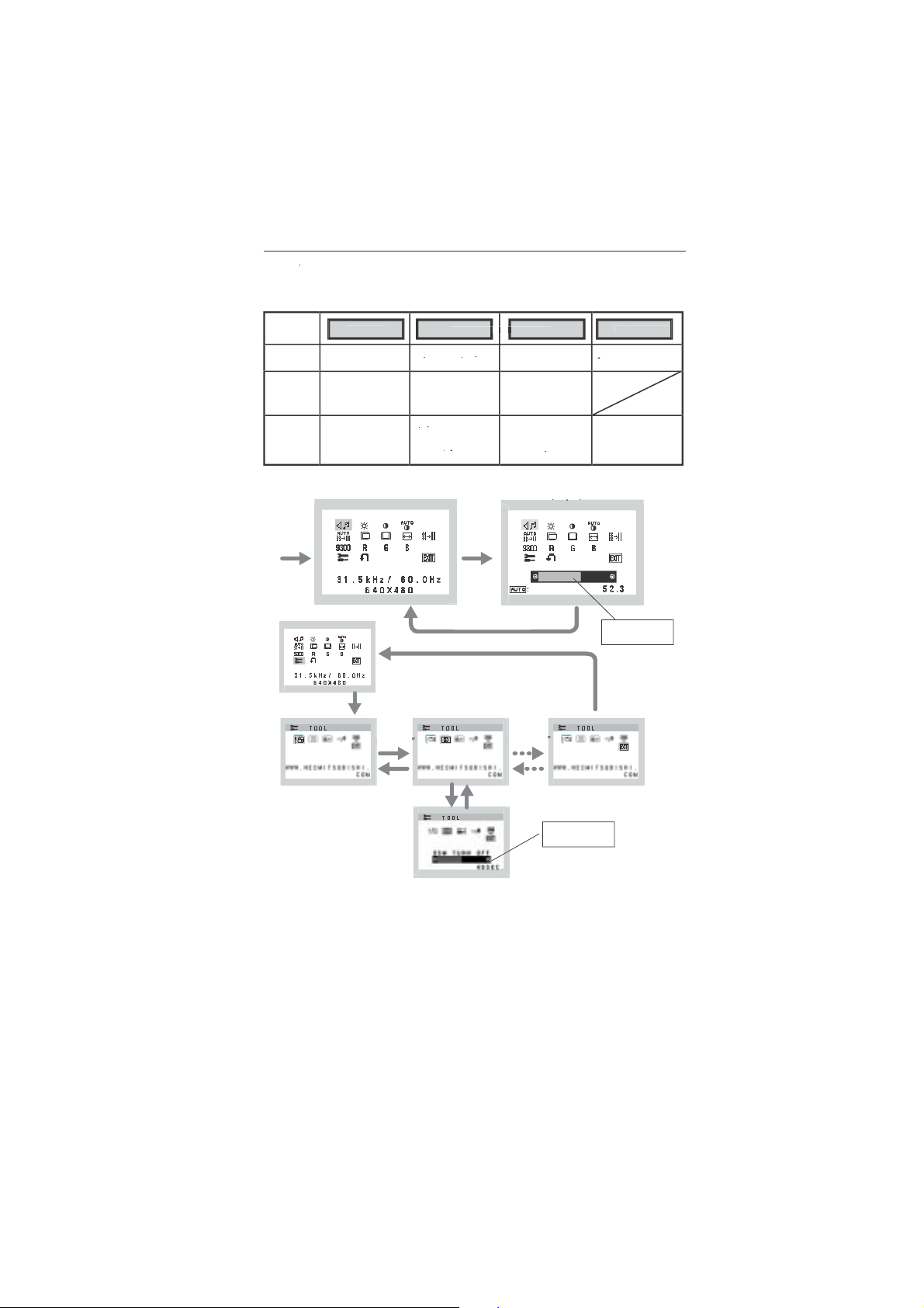
2. OSM structure
Press
“SELECT”
key
Main Menu (Icon Select)
Press
“SELECT”
key
Main Menu (Adjust)
VOLUME
MUTE
Press “SELECT” key
Example Tool:
%
Adjust by using
“–” or “+”
Press
“SELECT” key
Sub Menu (Icon Select)
Press
“–” or “+”
Press “SELECT” key
“SELECT” key
OSM TURN OFF
Sub Menu (Adjust)
English-6
1-30
Press
Press
“–” or “+”
Adjust by using
“–” or “+”

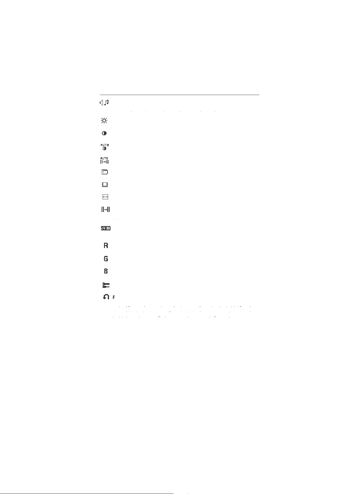
AUDIO
Audio volume icon is chosen, depending on the volume condition (AUTO/RESET).
BRIGHTNESS
Adjusts the overall image and background screen brightness.
CONTRAST
Adjusts the image brightness in relation to the background.
AUTO CONTRAST
Adjusts the image displayed for non-standard video inputs.
AUTO ADJUST
Automatically adjusts the Image Position, the H. Size and Fine setting.
LEFT/RIGHT
Controls Horizontal Image Position within the display area of the LCD.
DOWN/UP
Controls Vertical Image Position within the display area of the LCD.
H. SIZE
Adjusts the horizontal size by increasing or decreasing this setting.
FINE
Improves focus, clarity and image stability by increasing or decreasing this setting.
COLOUR CONTROL SYSTEMS
Four colour presets (9300/7500/6500/USER) select the desired color setting.
COLOUR RED
Increase or decreases Red. The change will appear on screen.
English
COLOUR GREEN
Increase or decreases Green. The change will appear on screen.
COLOUR BLUE
Increase or decreases Blue. The change will appear on screen.
TOOL
Selecting TOOL allows you to get into the sub menu.
FACTORY PRESET
Selecting Factory Preset allows you to reset all OSM control settings back to the factory settings. The RESET button
will need to be held down for several seconds to tage effect. Individual settings can be reset by highlighting the
control to be reset and pressing the RESET button.
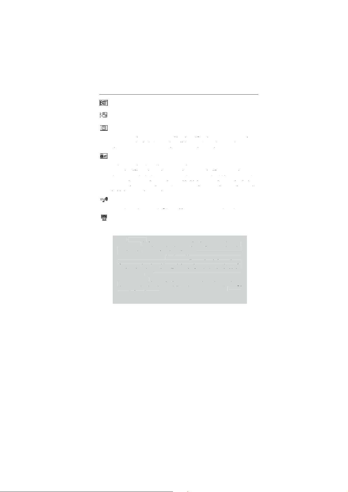
EXIT
Selecting EXIT allows you exit OSM menu/ sub menu.
LANGUAGE
OSM control menus are available in seven languages.
OSM TURN OFF
The OSM control menu will stay on as long as it is in use. In the OSM Turn OFF submenu, you can select how
long the monitor waits after the last touch of a button to shut off the OSM control menu. The preset choices are
10 - 120 seconds by 5 seconds step.
English-7
1-31

OSM LOCK OUT
This control completely locks out access to all OSM control functions without Brightness and Contrast. When
attempting to activate OSM controls while in the Lock Out mode, a screen will appear indicating the OSM are
locked out. To activate the OSM Lock Out function, press “AUTO/ RESET”, then “+” key and hold down
simultaneously. To de-activate the OSM Lock Out, press “AUTO/ RESET”, then “+” key and hold down simultaneously.
RESOLUTION NOTIFIER
If ON is selected, a message will appear on the screen after 30 seconds, notifying you that the resolution is not at
optimal resolution.
MONITOR INFO
Indicates the model and serial numbers of your monitor.
OSM Warning
OSM Warning menus disappear with Exit button.
NO SIGNAL: This function gives a warning when there is no signal present. After power is turned on or
when there is a change of input signal or video is inactive, the No Signal window will appear.
RESOLUTION NOTIFIER: This function gives a warning of use with optimized resolution. After power is
turned on or when there is a change of input signal or the video signal doesn’t have proper resolution, the
Resolution Notifier window will open. This function can be disabled in the TOOL menu.
OUT OF RANGE: This function gives a recommendation of the optimized resolution and refresh rate. After
the power is turned on or there is a change of input signal or the video signal doesn’t have proper timing,
the Out Of Range menu will appear.
English-8
1-32

Recommended use
Safety Precautions and Maintenance
FOR OPTIMUM PERFORMANCE, PLEASE NOTE
THE FOLLOWING WHEN SETTING UP AND
USING THE ACCUSYNC LCD COLOUR MONITOR:
• DO NOT OPEN THE MONITOR. There are no user serviceable parts inside and opening or removing covers may expose
you to dangerous shock hazards or other risks. Refer all servicing to qualified service personnel.
• Do not spill any liquids into the cabinet or use your monitor near water.
• Do not insert objects of any kind into the cabinet slots, as they may touch dangerous voltage points, which can be harmful
or fatal or may cause electric shock, fire or equipment failure.
• Do not place any heavy objects on the power cord. Damage to the cord may cause shock or fire.
• Do not place this product on a sloping or unstable cart, stand or table, as the monitor may fall, causing serious damage to
the monitor.
• When operating the LCD monitor with its AC 125-240V power supply, use a power supply aord that matches the power
supply voltage of the AC power outlet being used. The power supply cord you use must have been approved by and
comply with the safety standards of your country. (Type H05VV-F should be used in Europe).
• In U.K, use a BS-approved power cord with molded plug having a black (5A) fuse installed for use with this monitor.
If a power cord is not supplied with this monitor, please contact your supplier.
• Do not place any objects onto the monitor and do not use the monitor outdoors.
• The inside of the fluorescent tube located within the LCD monitor contains mercury. Please follow the bylaws or rules of
your municipality to dispose of the tube properly.
Immediately unplug your monitor from the wall outlet and refer servicing to qualified service personnel under the following
conditions:
• When the power supply cord or plug is damaged.
• If liquid has been spilled, or objects have fallen into the monitor.
• If the monitor has been exposed to rain or water.
• If the monitor has been dropped or the cabinet damaged.
• If the monitor does not operate normally by following operating instructions.
• Do not bend power cord.
• Do not use monitor in high temperature, humid, dusty, or oily areas.
• Do not cover vent on monitor.
• If monitor is broken, do not come in contact with the liquid crystal and handle with care.
• Allow adequate ventilation around the monitor so that heat can properly dissipate. Do not block
ventilated openings or place the monitor near a radiator or other heat sources. Do not put anything on
CAUTION
• Image Persistence: Image persistence is when a residual or “ghost” image of a previous image remains visible on the
screen. Unlike CRT monitors, LCD monitors’ image persistence is not permanent, but constant images being displayed for
a long period of time should be avoided.
To alleviate image persistence, turn off the monitor for as long as the previous image was displayed. For example, if an
image was on the monitor for one hour and a residual image remains, the monitor should be turned off for one hour to
erase the image.
NOTE: As with all personal display devices, NEC-Mitsubishi Electronics Display-Europe recommends using a moving
screen saver at regular intervals whenever the screen is idle or turning off the monitor when not in use.
top of monitor.
• The power cable connector is the primary means of detaching the system from the power supply. The
monitor should be installed close to a power outlet, which is easily accessible.
• Handle with care when transporting. Save packaging for transporting.
English
English-9
1-33

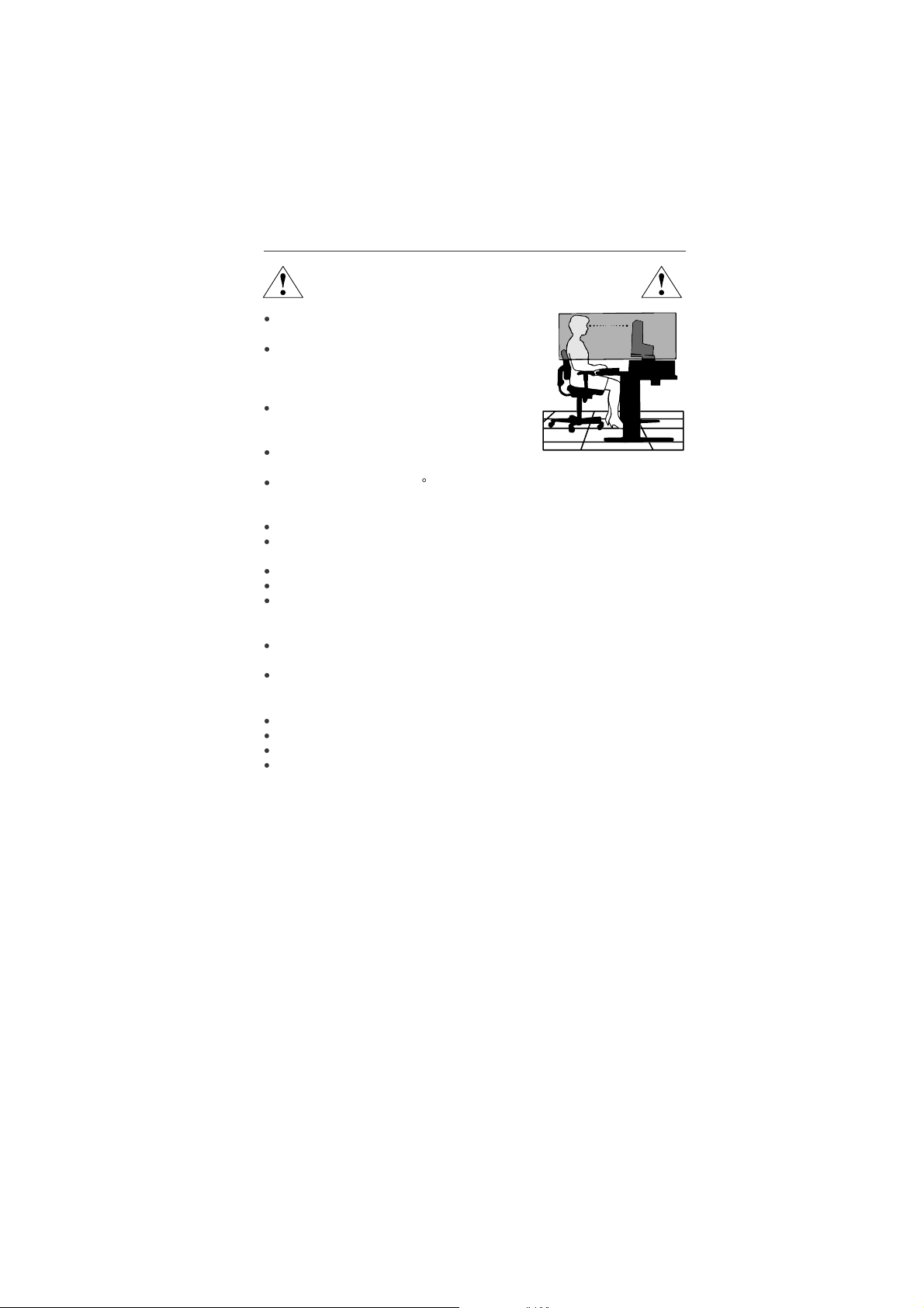
CORRECT PLACEMENT AND ADJUSTMENT OF THE MONITOR CAN
REDUCE EYE, SHOULDER AND NECK FATIGUE. CHECK THE
FOLLOWING WHEN YOU POSITION THE MONITOR:
• For optimum performance, allow 20 minutes for warm-up.
• Adjust the monitor height so that the top of the screen is at or slightly below eye level.
Your eyes should look slightly downward when viewing the middle of the screen.
• Position your monitor no closer than 40 cm and no further away than 70 cm from your
eyes. The optimal distance is 58 cm.
• Rest your eyes periodically by focusing on an object at least 6 m away. Blink often.
• Position the monitor at a 90° angle to windows and other light sources to minimize glare
and reflections. Adjust the monitor tilt so that ceiling lights do not reflect on your screen.
• If reflected light makes it hard for you to see your screen, use an antiglare filter.
• Clean the LCD monitor surface with a lint-free, non-abrasive cloth. Avoid using any
cleaning solution or glass cleaner!
• Adjust the monitor’s brightness and contrast controls to enhance readability.
• Use a document holder placed close to the screen.
• Position whatever you are looking at most of the time (the screen or reference material) directly in front of you to minimize
turning your head while you are typing.
• Avoid displaying fixed patterns on the monitor for long periods of time to avoid image persistence (after-image effects).
• Get regular eye checkups.
Ergonomics
To realize the maximum ergonomics benefits, we recommend the following:
• Use the preset Size and Position controls with standard signals.
• Use the preset Colour Setting.
• Use non-interlaced signals with a vertical refresh rate between 60-75 Hz.
• Do not use primary colour blue on a dark background, as it is difficult to see and may produce eye fatigue to insufficient
contrast.
English-10
1-34

Specifications LCD51VM Monitor
Monitor Specifications AccuSync LCD51VM Monitor Notes
LCD Module Diagonal: 38.1 cm/15 inches Active matrix; thin film transistor (TFT)
Native Resolution (Pixel Count): 1024 x 768 pitch; 250 cd/m
Input Signal Video: ANALOG 0.7 Vp-p/75 Ohms
Display Colours Analog input: 16,777,216 Depends on display card used.
Synchronization Range Horizontal: 31.5 kHz to 60 kHz Automatically
Viewing Angle Left/Right: -60°/+60°(CR>10)
Resolutions Supported Landscape: 720 x 400*
Active Display Area Horizontal: 304.1 mm
Speakers Practical Audio Output: 1.0 W + 1.0 W
Power Supply 100 - 240 V ~ 50/60 Hz
Current Rating 0.45 - 0.25 A
Dimensions Landscape: 347.4 mm (W) x 341.9 mm (H) x 168.5 mm (D) (with stand)
Weight 3.0 kg
Environmental Considerations
*1 Interpolated Resolutions: When resolutions are shown that are lower than the pixel count of the LCD module, text may appear different. This is
normal and necessary for all current flat panel technologies when displaying non-native resolutions full screen. In flat panel technologies, each dot on
the screen is actually one pixel, so to expand resolutions to full screen, an interpolation of the resolution must be done.
NOTE: Technical specifications are subject to change without notice.
Viewable Image Size: 38.1 cm/15 inches liquid crystal display (LCD); 0.297 mm dot
2
white luminance, 400/
450:1 contrast ratio, typical.
Sync: Separate sync.TTL Level (Positive/Negative)
Horizontal sync. Positive/Negative
Vertical sync. Positive/Negative
Vertical: 56 Hz to 75 Hz Automatically
Up/Down: -40°/+60°(CR>10)
1
: VGA Some systems may not support all
640 x 480*
800 x 600*
832 x 624*
1
@ 60 Hz to 75 Hz modes listed.
1
@ 56 Hz to 75 Hz NEC-Mitsubishi Electronics Display cites
1
@ 75 Hz recommended resolution at 75 Hz for
1024 x 768 @ 60 Hz to 75 Hz..................... optimal display performance.
Vertical: 228.1 mm
347.4 mm (W) x 296.2 mm (H) x 53.9 mm (D) (without stand)
Operating Temperature: 5 °C to 35 °C
Humidity: 30% to 80%
Altitude: 0 to 3,658 m
Storage Temperature: -10 °C to +60 °C
Humidity: 10% to 85%
Altitude: 0 to 12,192 m
English
English-11
1-35

Specifications LCD71VM Monitor
Monitor Specifications AccuSync LCD71VM Monitor Notes
LCD Module Diagonal: 43.2 cm/17 inches Active matrix; thin film transistor (TFT)
Native Resolution (Pixel Count): 1280 x 1024 pitch; 250 cd/m
Input Signal Video: ANALOG 0.7 Vp-p/75 Ohms
Display Colours Analog input: 16,194,277 Depends on display card used.
Synchronization Range Horizontal: 31.5 kHz to 81.1 kHz Automatically
Viewing Angle Left/Right: -70°/+70°(CR>10)
Resolutions Supported Landscape: 720 x 400*
Active Display Area Horizontal: 338 mm
Speakers Practical Audio Output: 1.0 W + 1.0 W
Power Supply 100 - 240 V ~ 50/60 Hz
Current Rating 0.75 - 0.4 A
Dimensions Landscape: 379 mm (W) x 383 mm (H) x 193 mm (D) (with stand)
Weight 4.6 kg
Environmental Considerations
*1 Interpolated Resolutions: When resolutions are shown that are lower than the pixel count of the LCD module, text may appear different. This is
normal and necessary for all current flat panel technologies when displaying non-native resolutions full screen. In flat panel technologies, each dot on
the screen is actually one pixel, so to expand resolutions to full screen, an interpolation of the resolution must be done.
NOTE: Technical specifications are subject to change without notice.
Viewable Image Size: 43.2 cm/17 inches liquid crystal display (LCD); 0.264 mm dot
2
white luminance, 450:1
contrast ratio, typical.
Sync: Separate sync.TTL Level (Positive/Negative)
Horizontal sync. Positive/Negative
Vertical sync. Positive/Negative
Vertical: 56 Hz to 75 Hz Automatically
Up/Down: -60°/+60°(CR>10)
1
: VGA Some systems may not
640 x 480*
800 x 600*
832 x 624*
1024 x 768*
1152 x 864*
1152 x 870*
1280 x 960*
1
@ 60 Hz to 75 Hz suppor t all modes listed.
1
@ 56 Hz to 75 Hz
1
@ 75 Hz
1
@ 60 Hz to 75 Hz
1
@ 70 Hz to 75 Hz
1
@ 75 Hz NEC-Mitsubishi Electronics Display cites
1
@ 60 Hz to 75 Hz recommended resolution at 75 Hz for
1280 x 1024 @ 60 Hz to 75 Hz................... optimal display performance.
Vertical: 270.3 mm
347.4 mm (W) x 296.2 mm (H) x 53.9 mm (D) (without stand)
Operating Temperature: 5 °C to 35 °C
Humidity: 30% to 80%
Altitude: 0 to 3,658 m
Storage Temperature: -10 °C to +60 °C
Humidity: 10% to 85%
Altitude: 0 to 12,192 m
English-12
1-36

Features
Reduced Footprint: Provides the ideal solution for environments requiring superior image quality but with size and weight
limitations. The small footprint and low weight allow it to be moved or transported easily from one location to another.
AccuColor Control Systems: Allows you to adjust the colours on your screen and customize the colour accuracy of your
monitor to a variety of standards.
OSM (On-Screen Manager) Controls: Allow you to quickly and easily adjust all elements of your screen image via simple to
use on-screen menus.
No-touch Auto Adjust: No-touch Auto Adjust automatically adjusts the monitor to optimal settings upon initial setup.
ErgoDesign Features: Enhance human ergonomics to improve the working environment, protect the health of the user and
save money. Examples include OSM controls for quick and easy image adjustments, tilt base for preferred angle of vision,
small footprint and compliance with MPRII and TCO guidelines for lower emissions.
Plug and Play: The Microsoft solution with the Windows 95/98/Me/2000/XP operating system facilitates setup and installation
by allowing the monitor to send its capabilities (such as screen size and resolutions supported) directly to your computer,
automatically optimizing display performance.
IPM (Intelligent Power Manager) System: Provides innovative power-saving methods that allow the monitor to shift to a
lower power consumption level when on but not in use, saving two-thirds of your monitor energy costs, reducing emissions
and lowering the air conditioning costs of the workplace.
Multiple Frequency Technology: Automatically adjusts monitor to the display card’s scanning frequency, thus displaying the
resolution required.
FullScan Capability: Allows you to use the entire screen area in most resolutions, significantly expanding image size.
VESA Standard Mounting Interface: Allows users to connect their AccuSync monitor to any VESA standard third party
mounting arm or bracket. Allows for the monitor to be mounted on a wall or an arm using any third party compliant device.
English
English-13
1-37

Troubleshooting
No picture
• The signal cable should be completely connected to the display card/computer.
• The display card should be completely seated in its slot.
• Check front power Switch and computer power switch should be in the ON position.
• Check to make sure that a supported mode has been selected on the display card or system being used. (Please
consult display card or system manual to change graphics mode.)
• Check the monitor and your display card with respect to compatibility and recommended settings.
• Check the signal cable connector for bent or pushed-in pins.
• Check the signal input.
Power Button does not respond
• Unplug the power cord of the monitor from the AC outlet to turn off and reset the monitor.
Image persistence
• Image persistence is when a “ghost” of an image remains on the screen even after the monitor has been turned off.
Unlike CRT monitors, LCD monitors’ image persistence is not permanent, but constant images being displayed for a
long period of time should be avoided.
To alleviate image persistence, turn the monitor off for as long as an image was displayed. For example, if an image
was on the monitor for one hour and a residual image remains, the monitor should be turned off for one hour to erase
the image.
NOTE: As with all personal display devices, NEC-Mitsubishi Electronics Displays recommends using a screen saver at
Image is unstable, unfocused or swimming is apparent
LED on monitor is not lit (no green or amber colour can be seen)
Display image is not sized properly
No Video
No Sound
regular intervals whenever the screen is idle or turning off the monitor when not in use.
• Signal cable should be completely attached to the computer.
• Use the OSM Image Adjust controls to focus and adjust display by increasing or decreasing the fine total. When the
display mode is changed, the OSM Image Adjust settings may need to be re-adjusted.
• Check the monitor and your display card with respect to compatibility and recommended signal timings.
• If your text is garbled, change the video mode to non-interlace and use 60 Hz refresh rate.
• Power Switch should be in the ON position and power cord should be connected.
• Use the OSM Image Adjust controls to increase or decrease the H.SIZE.
• Check to make sure that a supported mode has been selected on the display card or system being used.
(Please consult display card or system manual to change graphics mode.)
• If no video is present on the screen, turn the Power button off and on again.
• Make certain the computer is not in a power-saving mode (touch the keyboard or mouse).
• Check to see if speaker cable is properly connected.
• Check to see if mute is activated.
• Check to see if volume in OSM is set at minimum.
English-14
1-38

TCO’99
Congratulations! You have just purchased a
TCO’99 approved and labelled product! Your
choice has provided you with a product developed
for professional use. Your purchase has also
contributed to reducing the burden on the
environment and also to the further development
of environmentally adapted electronics products.
Why do we have environmentally labelled computers?
In many countries, environmental labelling has become an
established method for encouraging the adaptation of goods and
services to the environment. The main problem, as far as
computers and other electronics equipment are concerned, is that
environmentally harmful substances are used both in the products
and during the manufacturing. Since it has not been possible for
the majority of electronics equipment to be recycled in a
satisfactory way, most of these potentially damaging substances
sooner or later enter Nature.
There are also other characteristics of a computer, such as energy
consumption levels, that are important from the viewpoints of both
the work (Internal) and natural (external) environments. Since all
methods of conventional electricity generation have a negative
effect on the environment (acidic and climate-influencing
emissions, radioactive waste, etc.), it is vital to conserve energy.
Electronics equipment in offices consume an enormous amount of
energy since they are often left running continuously.
What does labelling involve?
This product meets the requirements for the TCO’99 scheme
which provides for international and environmental labelling of
personal computers. The labelling scheme was developed as a
joint effort by the TCO (The Swedish Confederation of Professional
Employees), Svenska Naturskyddsforeningen (The Swedish
Society for Nature Conservation) and Statens Energimyndighet
(The Swedish National Energy Administration).
The requirements cover a wide range of issues: environment,
ergonomics, usability, emission of electrical and magnetic fields,
energy consumption and electrical and fire safety.
The environmental demands concern restrictions on the presence
and use of heavy metals, brominated and chlorinated flame
retardants, CFCs (freons) and chlorinated solvents, among other
things. The product must be prepared for recycling and the
manufacturer is obliged to have an environmental plan which must
be adhered to in each country where the company implements its
operational policy. The energy requirements include a demand that
the computer and/or display, after a certain period of inactivity,
shall reduce its power consumption to a lower level in one or more
stages. The length of time to reactivate the computer shall be
reasonable for the user.
Labelled products must meet strict environmental demands, for
example, in respect of the reduction of electric and magnetic fields,
physical and visual ergonomics and good usability.
Environmental Requirements
Flame retardants
Flame retardants are present in printed circuit boards, cables,
wires, casings and housings. In turn, they delay the spread of fire.
Up to thirty percent of the plastic in a computer casing can consist
of flame retardant substances. Most flame retardants contain
bromine or chloride and these are related to another group of
environmental toxins, PCBs, which are suspected to give rise to
severe health effects, including reproductive damage in fisheating
birds and mammals, due to the bioaccumulative* processes.
Flame retardants have been found in human blood and
researchers fear that disturbances in foetus development may
occur.
TCO’99 demand requires that plastic components weighing more
than 25 grams must not contain flame retardants with organically
bound chlorine and bromine. Flame retardants are allowed in the
printed circuit boards since no substitutes are available.
Lead**
Lead can be found in picture tubes, display screens, solders and
capacitors. Lead damages the nervous system and in higher
doses, causes lead poisoning.
TCO’99 requirement permits the inclusion of lead since no
replacement has yet been developed.
Cadmium**
Cadmium is present in rechargeable batteries and in the
colourgenerating layers of certain computer displays. Cadmium
damages the nervous system and is toxic in high doses.
TCO’99 requirement states that batteries, the colourgenerating
layers of display screens and the electrical or electronics
components must not contain any cadmium.
Mercury**
Mercury is sometimes found in batteries, relays and switches,
Mercury damages the nervous system and is toxic in high doses.
TCO’99 requirement states that batteries may not contain any
Mercury. It also demands that no mercury is present in any of
the electrical or electronics components associated with the
display unit.
CFCs (freons)
CFCs (freons) are sometimes used for washing printed circuit
boards. CFCs break down ozone and thereby damage the ozone
layer in the stratosphere, causing increased reception on Earth
of ultraviolet light with consequent increased risks of skin cancer
(malignant melanoma).
The relevant TCO’99 requirement; Neither CFCs nor HCFCs
may be used during the manufacturing and assembly of the
product or its packaging.
*Bio-accumulative is defined as substances which accumulate
within living organisms.
**Lead, Cadmium and Mercury are heavy metals which are
Bio-accumulative.
To obtain complete information on the environmental criteria
document, order from:
TCO Development Unit
SE-114 94 Stockholm
SWEDEN
FAX Number: +46 8 782 92 07
E-mail (Internet): development@tco.se
You may also obtain current information on TCO’99 approved
and labelled products by visiting their website at:
http://www.tcodevelopment.com
English
English-15
1-39

Serial Number Information
Refer to the serial number information shown below.
Manufactured Year :
( Last digit )
Manufactured Month :
January to September 1 to 9
October X
November Y
December Z
LCD71VM-BK
EX.) SERIAL NUMBER LABEL
Model Name : LCD71VM
SERIAL NO. :
g g g g g g g g g g
Classification code :
Discriminate by cabinet color
White : 0
Black : 1
Running number :
Note : This running number doesn’t reset at each month.
(Example)
Jan.: 00001, 00002, 00003, ….., 01234,
Feb.: 01235, 01236, 01237, ….., 99999, 00001,
Mar.: 00002, 00003, 00004, …..
Factory Code:
NPG China factory: Y
Control Code:
For A ver. (U.S.A.): A
For B ver. (Europe): B
2-1

DISASSEMBLY
g Before you disassemble the set, turn off power and pull out the power plug.
g Use the proper screwdriver. If oversize or undersize screwdriver is used, screws may be damaged.
g Assembly is the opposite process of disassembly.
SYMBOL Part No for NPG DESCRIPTION CABINET COLOR
1 14300511 SC,PL-CPIMS*4*10*3G White
1 14300501 SC,PL-CPIMSx4x10x3K Black
2 14900121 HINGE UNIT,L172R6 ---
1
1
2
3-1

SYMBOL Part No for NPG DESCRIPTION CABINET COLOR
3 14000411 SC,CBISSx3x8x3G White
3 14000401 SC,CBISSx3x8x3K Black
4 14000421 SC,CBIBSx3x16x3G White
4 1400026 1 SCREW (3*16 TRUSS HEAD/B TITE) Black
5 10103681 BACK,L172R6-WH-NSP White
5 10103691 BACK,L172R6-BK-NSP Black
5
3
4
3-2

SYMBOL Part No for NPG DESCRIPTION
6 14000391 SC,CBIPS*3*10*15B
7 AS0R51ML SW INSERT ASSY
8 JN100021 SPEAKER ASSY
8
S801
7
6
SYMBOL Part No for NPG DESCRIPTION CABINET COLOR Ver
9 10103811 BEZEL,L172R6-WH-NSP-ASSY White A ver
9 10103831 BEZEL,L172R6-BK-NSP-ASSY Black A ver
9 10103851 BEZEL,L172R6-BK(B)-NSP-AS Silver/Black B ver
10 11301621 KNOB CONTROL,L172R6-WH White A ver
10 11301631 KNOB CONTROL,L172R6-BK Black A ver
10 11301831 KNOB CONTROL,L172R6-SL Silver/Black B ver
9
10
3-3

SYMBOL Part No for NPG DESCRIPTION
11 14300521 SC,CFIMS*3*4*3K
12 14300201 4#-40TX4.8HLX4X5-NI/W
CN52
CN53
CN54
CN55
12
11
SYMBOL Part No for NPG DESCRIPTION
13 14000121 SCREW CUP(3*8*15BF)
14 12301161 SHIELD EMI,L172R6
15 12000961 CHASSIS BASE,L172R6
16 14300521 SC,CFIMS*3*4*3K
1415
16
13
3-4
S404

SYMBOL Part No for NPG DESCRIPTION
17 RC200302 WIRE 30P-30P L150 LVDS(LG)
18 JG572011 TFT LM170E 01 LPL
17
18
SYMBOL Part No for NPG DESCRIPTION
19 14000121 SCREW CUP(3*8*15BF)
20 14300031 SCREW(PL-CPIMS*4*10*15BF)
21 RC200272 WIRE 9P-9P P=2.0 L260
19
S405
S403
19
20
S502
21
3-5

SYMBOL Part No for NPG DESCRIPTION
22 AM0R61ML MAIN INSERT ASSY
23 JM100041 POWER B/D (17"LG)
23
22
SYMBOL Part No for NPG DESCRIPTION CABINET COLOR
24 11001941 STAND COVER T,L172R6-WH White
24 11001951 STAND COVER T,L172R6-BK Black
25 12301281 SHIELD TCO,L172R6 --26 14000491 SC,CBIPS*4*8*15B --27 11001971 STAND COVER B,L172R6-WH White
27 11001981 STAND COVER B,L172R6-BK Black
28 17001441 FOOT RUBBER ---
24 25
27
26
28
3-6

ADJUSTMENT PROCEDURES
TABLE OF CONTENTS
1. Application ............................................................................................................................. 4-2
2. Default Setting ...................................................................................................................... 4-2
3. Basic Operation .................................................................................................................... 4-2
3.1 Basic Key Function ............................................................................................................. 4-2
3.2 Hot Key for Factory Adjust .................................................................................................. 4-3
3.3 Hot Key for Burn-in Mode ................................................................................................... 4-4
4. Adjustment ............................................................................................................................ 4-5
4.1 Measuring Instruments, Jigs and Tools ............................................................................... 4-5
4.2 Power-supply Voltage ......................................................................................................... 4-5
4.3 Power Circuit Closure ......................................................................................................... 4-5
4.4 ADC Bias and Gain Adjust .................................................................................................. 4-5
4.5 Panel Brightness Check ...................................................................................................... 4-6
4.6 Panel Color Check .............................................................................................................. 4-6
4.7 Color Temperature Check ................................................................................................... 4-6
Page
5. Reference Signal Timing ....................................................................................................... 4-7
6. Factory Mode Explanations .................................................................................................. 4-8
7. Preset Timing Sheet .............................................................................................................. 4-11
4-1

1. Application
This adjustment specification should be applied to the LCD71VM (L172R6).
2. Default Setting
Item Condition
Power Supply AC100V~240Vac
Input Freq.
1280×1024@75Hz
Volume 50%
Mute OFF
Brightness 100%
Contrast 50%
OSM
SETTING
Color Temp. USER (R: 100%, G: 100%, B: 100%)
OSM Time Off 45 sec.
OSM Lock Out NO
Resolution notifier ON
OSD/OSM SETTING OSM
URL SETTING WWW.NECMITSUBISHI.COM
LANGUAGE ENGLISH
3. Basic Operation
3.1 Basic Key Function
Button
OSM Off
OSM On
(Icon selection
stage)
OSM On
(Adjustment
stage)
SELECT
OSM displayed
Moves to
stage
Moves to Icon
selection stage
Adjustment
− +
Shortcut to bright
adjust window
Cursor moves left Cursor moves right
Adjust value
decrease or
Cursor for adjust
moves left
Shortcut to volume
adjust window
Adjust value
increase or
Cursor for adjust
moves right
AUTO/RESET
“Auto adjust“ function
Reset operation
Mute off/on Volume
adjustment window
4-2

3.2 Hot Key for Factory Adjust
a) Press “Select” button then open OSM menu.
Select
b) OSM select to “TOOL” menu by “Plus” or “Minus” button.
+ or -
c) Press “Select button” into “TOOL” menu.
Select
d) OSM select to “MODE” item and Press “Select button” into “MODE” menu.
+ or - Select
e) Press “Plus “ + ”Minus” and “Auto/Reset” button then into Factory mode.
+,- and Auto/Reset
4-3
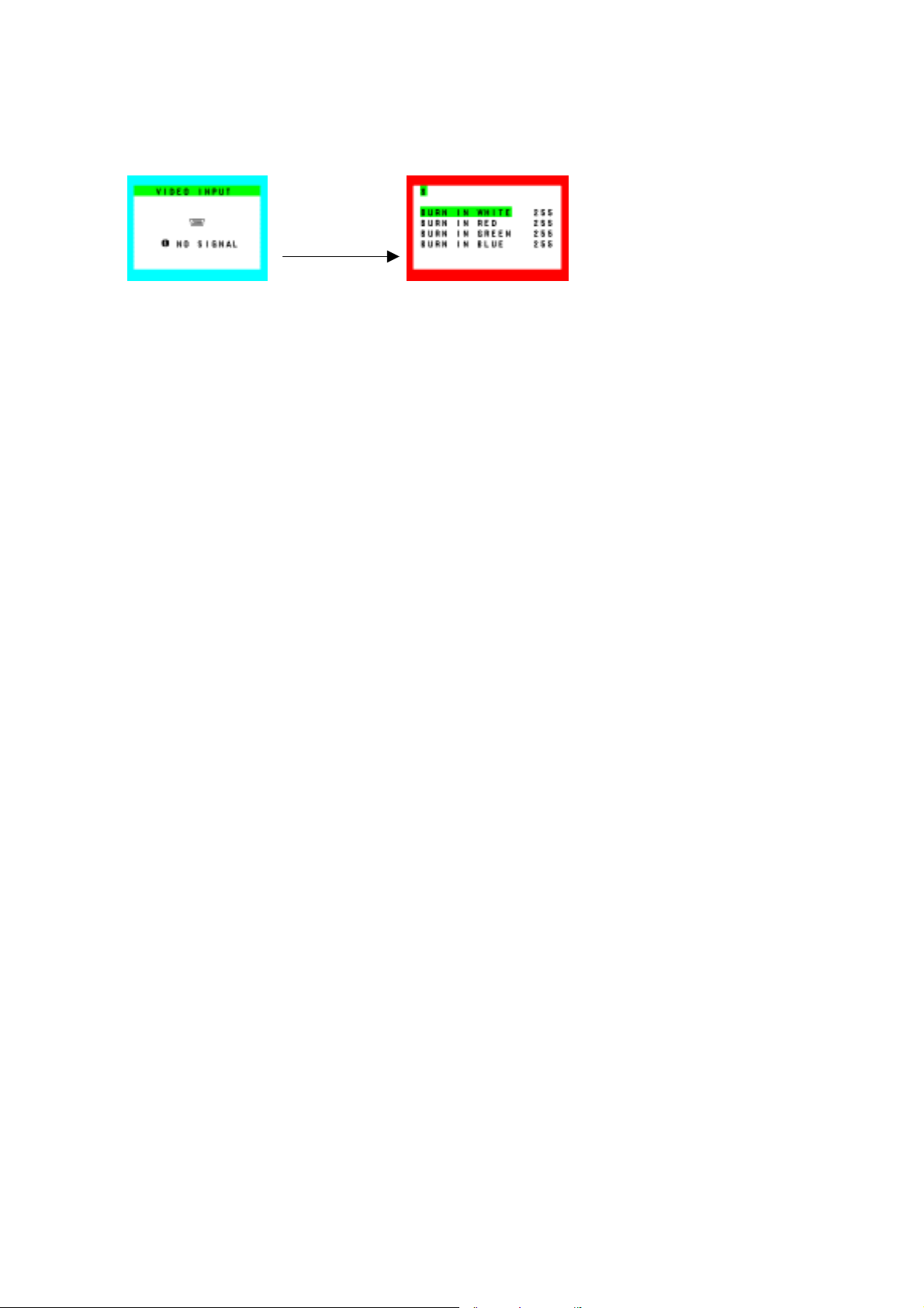
3.3 Hot Key for Burn-in Mode
a) No signal input.
b) Press “Plus” + “Minus” and “Auto/Reset” button then into Burn-in mode.
+,- and Auto/Reset
4-4

4. Adjustment
4.1 Measuring Instruments, Jigs and Tools
The measuring instruments, jigs, and tools required at the time of the adjustment of the unit to be adjusted
are as specified below.
a. A signal generator that can generate an output of signal timing produced by the adjusted (*) VG-819 or
specified in [4. Setting method for the VG-819.] In this case, however, this signal generator should be
capable of displaying all white and all black as a screen display pattern.
* The word “adjusted” shall mean that the amplitude of each signal R, G, B, which is output from the signal
generator, is maintained at 0.7Vp-p ± 0.05V when a load of 75Ω is connected.
4.2 Power-supply Voltage
INPUT: 100Vac ~ 240Vac
4.3 Power Circuit Closure
1) Connect the suitable cable of the VG-819 according to the setting mode.
2) Turn on the Power switch of the VG-819.
3) Connect the AC power cable to the unit being adjusted.
4) Turn on the Power switch of the unit being adjusted.
5) Af ter the completion of signal discrimination, the LED is turned green.
4.4 ADC Bias and Gain Adjust
1) Enter an input signal of 1280×1024 (75Hz), in 32-gray gradation.
2) Enter the factory mode according to “3.2 Hot key for Factory Adjust”
3) Press the (+) or (−) buttons several times to display the [AUTO CONTRAST] adjust menu.
1 2 3 4 5 6 7
AUTO
GAIN RED 244
GAIN GREEN 250
GAIN BLUE 220
OFFSET RED 90
OFFSET GREEN 85
OFFSET BLUE 82
4) Pressing the SELECT button, adjust the cursor to [AUTO]. When the AUTO/RESET button is pressed,
adjustment of the bias and the gain is carried out.
5) When adjustments have been finished, press the power switch OFF → ON to close the factory mode.
4-5

4.5 Panel Brightness Check
1) Enter the input signal of 1280×1024 (75Hz), in Full white pattern.
2) Proceed “Factory Preset” function of miscellaneous menu.
3) OSM setting “BRIGHTNESS” to Max. (100%) and “CONTRAST” to 100%.
4) Color temperature setting to “USER” (R: 100%, G: 100%, B: 100%).
2
5) Check the center luminance should ≥ 200cd/m
.
4.6 Panel Color Check
1) Enter an input signal of 1280×1024 (75Hz), in Full white pattern.
2) Proceed “Factory Preset” function.
Brightness: 100%
Contrast: 100%
3) Color temperature setting to “USER” (R: 100%, G: 100%, B: 100%).
4) Check the center color coordination.
x = 313 ±0.03 y = 329 ±0.03
4.7 Color Temperature Check
1) Enter an input signal of 1280×1024 (75Hz), in Full white pattern.
2) OSM “BRIGHTNESS” setting to Max. (100%) and “CONTRAST” setting to 50%.
3) Color temperature setting to each color.
4) Each color temperature setting as below:
9300K: x = 0.283 ±0.03 y = 0.297 ±0.03
7500K: x = 0.299 ±0.03 y = 0.315 ±0.03
6500K: x = 0.313 ±0.03 y = 0.329 ±0.03
4-6

5. Reference Signal Timing
Item
Pixel frequency
Horizontal frequency
Line Time total
Horizontal active display
Horizontal sync pulse
Horizontal back porch
Horizontal front porch
Horizontal sync polarity
Vertical Frequency
Frame time total
Vertical active display
Vertical sync pulse
Vertical back porch
Vertical front porch
Vertical sync polarity
Abbreviation
fc 135.00MHz
fh 79.98kHz
Th 12.50us 1688CLK
Thd 9.48us 1280CLK
Thp 1.07us 144CLK
Thb 1.84us 248CLK
Thf 0.12us 16CLK
POS
fv 75.03Hz
Tv 13.33ms 1066H
Tvd 12.80ms 1024h
Tvp 0.04ms 3H
Tvb 0.48us 38H
Tvf 0.01ms 1H
POS
VESA 1280x1024 75Hz
4-7

6. Factory Mode Explanations
1 2 3 4 5 6 7
HOURS RUNNING
ON 104H 38M
OFF 224H 40M
FACTORY RESET
1 2 3 4 5 6 7
AUTO
GAIN RED 244
GAIN GREEN 250
GAIN BLUE 220
OFFSET RED 90
OFFSET GREEN 85
OFFSET BLUE 82
1 2 3 4 5 6 7
OSD DESIGN 0
OSD SELECT OSM
URL 1
FIRST AUTO ON
THRESHOLD 4
ON: Accumulated time during the reception of input signals
(LED: green)
OFF: Accumulated time in the power-saving mode and soft
power off mode (Only AC power input).
(LED: amber or off)
* The accumulated time (hours running) is reset when
FACTORY RESET is executed.
FACTORY PRESET: All data are reset to the initial values.
AUTO: Auto-adjustments for the gain and the offset.
GAIN R/G/B: It is possible to adjust the gain values of
R, G, B, respectively.
* This value use Auto contrast of user menu.
OFFSET R/G/B: It is possible to adjust the offset values of
R, G, B, respectively.
OSD DESIGN: No Used.
OSD SELECT: The OSD/OSM display is changed over for
the OSM menu.
OSM (Setting for shipment)
OSD
URL: Display or no display of URL (Internet ad dress)
0: Not displayed
1: Displayed (WWW.NECMITSUBISHI.COM): Setting for
shipment (for North America and Europe version)
2: Displayed (WWW.NMV.CO.JP): (for Japan)
FIRST AUTO: Non touch auto adjust function switch.
ON: NTAA function enable. (Setting for shipment)
OFF: NT AA function disable.
THRESHOLD: Image detect level of auto adjust.
0: Min
16: Max
4: Initial
4-8

1 2 3 4 5 6 7
AUTO COUNT 142
AUTO CONT COUNT 55
PWMO PERIOD 53
PWMO MAX 35
PWMO MIN 33
1 2 3 4 5 6 7
F-GAIN RED 262
F-GAIN GREEN 256
F-GAIN BLUE 265
OFFSET1 RED 32
OFFSET1 GREEN 32
OFFSET1 BLUE 32
AUTO COUNT: No. of auto-adjustment trials conducted by
the user.
* This value can reset by factory reset of service menu.
AUTO CONT COUNT: No. of auto-contrast control trials
conducted by the user
* This value can reset by factory reset of service menu.
PWMO PREIOD: Backlight brightness control frequency.
Initial: 49
PWMO MAX: Brightness control Max.
Initial: 49
PWMO MIN: Brightness control Min.
Initial: 21
F-GAIN R/G/B: It is factory auto gain result value. If proceed
factory preset of user menu then overwrite
gain seconds menu in this value.
OFFSET1 R/G/B: It is first stage offset control. Initial: 32
* Don’t change this value.
4-9

V
1 2 3 4 5 6 7
H FREQ STABLE 2
V FREQ STABLE 1
STABLE COUNT 4
H FREQ UNSTABLE 2
V FREQ UNSTABLE 1
UNSTABLE COUNT 1
1 2 3 4 5 6 7
HOURS RUNNING(FACT)
ON 105H 45M
OFF 224H 40M
F/W
ERSION:V0.28
H FREQ ST ABLE: Input signal st able condition from unst able.
Initial: 2
V FREQ ST ABLE: In put signal st able condition from unst able.
Initial: 1
STABLE COUNT: Input signal stable condition from unstable.
Initial: 4
H FREQ UNSTABLE: Input signal unstable condition from
stable. Initial: 2
V FREQ UNSTABLE: Input signal unstable condition from
stable. Initial: 1
UNSTABLE COUNT: Input signal unstable condition from
stable. Initial: 1
ON: Tot al accumulated time during the reception of input
signals (LED: green)
OFF: Accumulated time in the power-saving mode and soft
power off mode (Only AC power input).
(LED: amber or off)
* The accumulated time (hours running) is not reset even
when FACTORY RESET is executed.
F/W VERSION: Firmware version
4-10

7. Preset Timing Sheet
No. 1 2
Item Abbreviation VGA 640x480 60Hz MAC 640x480
Pixel frequency fc 25.175MHz 30.24MHz
Horizontal frequency fh 31.47kHz 35.00kHz
Line Time total Th 31.78us 800CLK 28.57us 864CLK
Horizontal active display Thd 25.42us 640CLK 21.16us 640CLK
Horizontal sync pulse Thp 3.81us 96CLK 2.12us 64CLK
Horizontal back porch Thb 1.91us 48CLK 3.17us 96CLK
Horizontal front porch Thf 0.64us 16CLK 2.12us 64CLK
Horizontal sync polarity NEG NEG
Vertical Frequency fv 59.992Hz 66.66Hz
Frame time total Tv 16.68ms 525H 15.00ms 525H
Vertical active display Tvd 15.25ms 480H 13.71ms 480H
Vertical sync pulse Tvp 0.06ms 2H 0.09ms 3H
Vertical back porch Tvb 1.02ms 33H 1.11ms 39H
Vertical front porch Tvf 0.35ms 10H 0.09ms 3H
Vertical sync polarity NEG NEG
No. 3 4
Item Abbreviation VGA 640x480 72Hz VESA 640x480 75Hz
Pixel frequency fc 31.500MHz 31.500MHz
Horizontal frequency fh 37.86kHz 37.50kHz
Line Time total Th 26.41us 832CLK 26.67us 840CLK
Horizontal active display Thd 20.32us 640CLK 20.32us 640CLK
Horizontal sync pulse Thp 1.27us 40CLK 2.03us 64CLK
Horizontal back porch Thb 4.06us 128CLK 3.81us 120CLK
Horizontal front porch Thf 0.76us 24CLK 0.51us 16CLK
Horizontal sync polarity NEG NEG
Vertical Frequency fv 72.81Hz 75.00Hz
Frame time total Tv 13.73ms 520H 13.33ms 500H
Vertical active display Tvd 12.68ms 480H 12.80ms 480H
Vertical sync pulse Tvp 0.08ms 3H 0.08ms 3H
Vertical back porch Tvb 0.74ms 28H 0.43ms 16H
Vertical front porch Tvf 0.24ms 9H 0.03ms 1H
Vertical sync polarity NEG NEG
No. 5 6
Item Abbreviation VGA 720x350 70Hz VGA 720x400 70Hz
Pixel frequency fc 28.322MHz 28.322MHz
Horizontal frequency fh 31.47kHz 31.47kHz
Line Time total Th 31.78us 900CLK 31.78us 900CLK
Horizontal active display Thd 25.42us 720CLK 25.42us 720CLK
Horizontal sync pulse Thp 3.81us 108CLK 3.81us 108CLK
Horizontal back porch Thb 1.91us 54CLK 1.91us 54CLK
Horizontal front porch Thf 0.64us 18CLK 0.63us 18CLK
Horizontal sync polarity POS NEG
Vertical Frequency fv 70.087Hz 70.087Hz
Frame time total Tv 14.27ms 449H 14.27ms 449H
Vertical active display Tvd 11.12ms 350H 12.71ms 400H
Vertical sync pulse Tvp 0.06ms 2H 0.06ms 2H
Vertical back porch Tvb 1.91ms 60H 1.11ms 35H
Vertical front porch Tvf 1.18ms 37H 0.38ms 12H
Vertical sync polarity NEG POS
4-11

No. 7 8
Item Abbreviation VESA 800x600 56Hz VESA 800x600 60Hz
Pixel frequency fc 36.00MHz 40.00MHz
Horizontal frequency fh 35.16kHz 37.88kHz
Line Time total Th 28.44us 1024CLK 26.40us 1065CLK
Horizontal active display Thd 22.22us 800CLK 20.00us 800CLK
Horizontal sync pulse Thp 2.00us 72CLK 3.20us 128CLK
Horizontal back porch Thb 3.56us 128CLK 2.20us 88CLK
Horizontal front porch Thf 0.67us 24CLK 1.00us 40CLK
Horizontal sync polarity POS POS
Vertical Frequency fv 56.25Hz 60.32Hz
Frame time total Tv 17.78ms 625H 16.58ms 628H
Vertical active display Tvd 17.07ms 600H 15.84ms 600H
Vertical sync pulse Tvp 0.06ms 2H 0.11ms 4H
Vertical back porch Tvb 0.63ms 22H 0.61ms 23H
Vertical front porch Tvf 0.03ms 1H 0.03ms 1H
Vertical sync polarity POS POS
No. 9 10
Item Abbreviation VESA 800x600 72Hz VESA 800x600 75Hz
Pixel frequency fc 50.000MHz 49.500MHz
Horizontal frequency fh 48.08kHz 46.88kHz
Line Time total Th 20.80us 1040CLK 21.33us 1056CLK
Horizontal active display Thd 16.00us 800CLK 16.16us 800CLK
Horizontal sync pulse Thp 2.40us 120CLK 1.62us 80CLK
Horizontal back porch Thb 1.28us 64CLK 3.23us 160CLK
Horizontal front porch Thf 1.12us 56CLK 0.32us 16CLK
Horizontal sync polarity POS(/NEG) POS
Vertical Frequency fv 72.19Hz 75.00Hz
Frame time total Tv 13.85ms 666H 13.33ms 625H
Vertical active display Tvd 12.48ms 600H 12.80ms 600H
Vertical sync pulse Tvp 0.13ms 6H 0.06ms 3H
Vertical back porch Tvb 0.48ms 23H 0.45ms 21H
Vertical front porch Tvf 0.77ms 37H 0.02ms 1H
Vertical sync polarity POS(/NEG) POS
No. 11 12
Item Abbreviation MAC 832x624 VESA 1024x768 60Hz
Pixel frequency fc 57.28MHz 65.000MHz
Horizontal frequency fh 49.73kHz 48.35kHz
Line Time total Th 20.11us 1152CLK 20.68us 1344CLK
Horizontal active display Thd 14.52us 832CLK 15.75us 1024CLK
Horizontal sync pulse Thp 1.12us 64CLK 2.09us 136CLK
Horizontal back porch Thb 3.91us 224CLK 2.46us 160CLK
Horizontal front porch Thf 0.56us 32CLK 0.37us 24CLK
Horizontal sync polarity NEG NEG
Vertical Frequency fv 74.55Hz 60.00Hz
Frame time total Tv 13.41ms 667H 16.67ms 806H
Vertical active display Tvd 12.55ms 624H 15.88ms 768H
Vertical sync pulse Tvp 0.06ms 3H 0.12ms 6H
Vertical back porch Tvb 0.78ms 39H 0.60ms 29H
Vertical front porch Tvf 0.02ms 1H 0.06ms 3H
Vertical sync polarity NEG NEG
4-12

No. 13 14
Item Abbreviation VESA 1024x768 70Hz VESA 1024x768 75Hz
Pixel frequency fc 75.000MHz 78.75MHz
Horizontal frequency fh 56.48kHz 60.02kHz
Line Time total Th 17.71us 1328CLK 16.66us 1312CLK
Horizontal active display Thd 13.65us 1024CLK 13.00us 1024CLK
Horizontal sync pulse Thp 1.81us 136CLK 1.22us 96CLK
Horizontal back porch Thb 1.92us 144CLK 2.24us 176CLK
Horizontal front porch Thf 0.32us 24CLK 0.20us 16CLK
Horizontal sync polarity NEG POS
Vertical Frequency fv 70.07Hz 75.03Hz
Frame time total Tv 14.27ms 806H 13.33ms 800H
Vertical active display Tvd 13.60ms 768H 12.80ms 768H
Vertical sync pulse Tvp 0.11ms 6H 0.05ms 3H
Vertical back porch Tvb 0.51ms 29H 0.47ms 28H
Vertical front porch Tvf 0.05ms 3H 0.02ms 1H
Vertical sync polarity NEG POS
No. 15 16
Item Abbreviation MAC 1152x870 75Hz VESA 1280x960 60Hz
Pixel frequency fc 100.00MHz 108.00MHz
Horizontal frequency fh 68.82kHz 60.00kHz
Line Time total Th 14.56us 1456CLK 16.67us 1800CLK
Horizontal active display Thd 11.52us 1152CLK 11.85us 1280CLK
Horizontal sync pulse Thp 1.28us 128CK 1.04us 112CLK
Horizontal back porch Thb 1.44us 144CLK 2.89us 312CLK
Horizontal front porch Thf 0.32us 32CLk 0.89us 96CLK
Horizontal sync polarity NEG POS
Vertical Frequency fv 75.06Hz 60.00Hz
Frame time total Tv 13.32ms 915H 16.67ms 1000H
Vertical active display Tvd 12.67ms 870H 16.0ms 960H
Vertical sync pulse Tvp 0.04ms 3H 0.05ms 3H
Vertical back porch Tvb 0.57ms 39H 0.60ms 36H
Vertical front porch Tvf 0.04ms 3H 0.017ms 1H
Vertical sync polarity NEG POS
No. 17 18
Item Abbreviation VESA 1280x960 75Hz VESA 1280x1024 60Hz
Pixel frequency fc 129.60MHz 108.00MHz
Horizontal frequency fh 75.000kHz 63.981kHz
Line Time total Th 13.333us 1728CLK 15.63us 1688CLK
Horizontal active display Thd 9.877us 1280CLK 11.85us 1280CLK
Horizontal sync pulse Thp 0.988us 128CLK 1.04us 112CLK
Horizontal back porch Thb 1.975us 256CLK 2.30us 248CLK
Horizontal front porch Thf 0.494us 64CLK 0.44us 48CLK
Horizontal sync polarity POS POS
Vertical Frequency fv 75.000Hz 60.02Hz
Frame time total Tv 13.333ms 1000H 16.67ms 1066H
Vertical active display Tvd 12.800ms 960H 16.00ms 1024H
Vertical sync pulse Tvp 0.040ms 3H 0.05ms 3H
Vertical back porch Tvb 0.480ms 36H 0.59ms 38H
Vertical front porch Tvf 0.013ms 1H 0.02ms 1H
Vertical sync polarity POS POS
4-13

MODE
No. 19
Item Abbreviation VESA 1280x1024 75Hz
Pixel frequency fc 135.00MHz
Horizontal frequency fh 79.98kHz
Line Time total Th 12.50us 1688CLK
Horizontal active display Thd 9.48us 1280CLK
Horizontal sync pulse Thp 1.07us 144CLK
Horizontal back porch Thb 1.84us 248CLK
Horizontal front porch Thf 0.12us 16CLK
Horizontal sync polarity POS
Vertical Frequency fv 75.03Hz
Frame time total Tv 13.33ms 1066H
Vertical active display Tvd 12.80ms 1024H
Vertical sync pulse Tvp 0.04ms 3H
Vertical back porch Tvb 0.48us 38H
Vertical front porch Tvf 0.01ms 1H
Vertical sync polarity POS
4-14

INSPECTION
TABLE OF CONTENTS
1. General Description ------------------------------------------------------------------------------------------ 5-2
2. Electrical Characteristics ------------------------------------------------------------------------------------ 5-3
2.1 Power Supply --------------------------------------------------------------------------------------------- 5-3
2.2 LCD without Acrylic Panel ----------------------------------------------------------------------------- 5-4
2.3 Video Interface -------------------------------------------------------------------------------------------- 5-4
2.4 Audio System --------------------------------------------------------------------------------------------- 5-6
2.5 External Inspection on the LCD Module ------------------------------------------------------------ 5-7
3. Electrical Inspection ------------------------------------------------------------------------------------------ 5-11
3.1 Function switch check ---------------------------------------------------------------------------------- 5-11
3.2 Frequency change --------------------------------------------------------------------------------------- 5-11
3.3 Performance Check ------------------------------------------------------------------------------------- 5-11
Page
3.4 Check Power Manage Function ---------------------------------------------------------------------- 5-11
3.5 Inspection on Audio function -------------------------------------------------------------------------- 5-12
4. Safety Test ------------------------------------------------------------------------------------------------------ 5-13
4.1 Input Current Measurements -------------------------------------------------------------------------- 5-13
4.2 Power Source/Earth Connections -------------------------------------------------------------------- 5-13
4.3 Dielectric Strength Test --------------------------------------------------------------------------------- 5-14
4.4 Leakage Current Test ----------------------------------------------------------------------------------- 5-14
4.5 Insulation Resistance Test ----------------------------------------------------------------------------- 5-15
5. Inspection of PLUG & PLAY Communication and OSM "MONITOR INFORMATION"
for Model Name/ Serial Number --------------------------------------------------------------------------- 5-16
5.1 System Connection -------------------------------------------------------------------------------------- 5-16
5.2 Input Signal ------------------------------------------------------------------------------------------------ 5-16
5.3 Program ---------------------------------------------------------------------------------------------------- 5-16
5.4 Operation --------------------------------------------------------------------------------------------------- 5-17
5.5 EDID Data File -------------------------------------------------------------------------------------------- 5-20
5.6 EDID Write Protect Cancel Signal Timing ---------------------------------------------------------- 5-20
Appendix Reference Signal Timings ---------------------------------------------------------------------- 5-21
5-1

1. General Description
Product Specifications
LCD Module
Frequency
Pixel Clock
Viewable Size
Multi Pixel
Digital Control
Color Control
On Screen Display
Power Management
Plug and Play
USB Hub
Speaker
Headphone Jack
Microphone Jack
Auto Adjustment
Brightness control range
Controllable Function
Input Signal (analog)
*: When user setting is minimum,
30% = (Brightness value [cd/m
LG-Philips LM170E01-A4
Pixel Pitch 0.264mm
Resolution 1280x1024 pixels (SXGA)
Color 16.19 million color (R, G, B: 6bit + FRC)
Brightness 250cd/m2 (Typical)
Contrast Ratio 450:1 (Typical)
70/70(L/R), 60/60(U/D) (CR>=10: Typical)
Viewing Angle
60/60(L/R), 50/45(U/D) (CR>=10: Minimum)
80/80(L/R), 70/70(U/D) (CR>=5: Typical)
70/70(L/R), 60/55(U/D) (CR>=5: Minimum)
Horizontal 31.5 – 81.1kHz
Vertical 56.2 – 75.1Hz
25.1 – 135.0MHz
337.92 x 270.336mm
Yes (with smoothing)
Yes
Yes (3 preset memory + 1 user color)
Yes
Yes (VESA DPMS)
Yes (VESA DDC2B/2Bi)
No
Yes
Yes
No
Yes (Position / Size / Phase)
30% - 100% *
Volume, Mute, Brightness, Contrast, Auto-Contrast,
Analog
Auto-Adjust, H. Posi, V. posi, H. Size, Fine, Color
Control, Language, OSM Turn Off, OSM Lock Out,
Resolution Nortifier, Monitor Info., Factory Reset
Signal Drive Separated Direct Drive
Video
RGB 0.7Vp-p
Input Impedance 75 ohm
Sync Separate sync: TTL Level (Positive / Negative)
Input Mini D-sub 15pin
DDC DDC2B
Signal Cable Mini D-sub 15pin Signal Cable (L=1.8m)
2
] when user controls Brightness Max) x 0.3
5-2

Power Supply
Current Rating
Operational Environment
Storage Environment
Dimension
Weight
Kensington compatible Security Lock
VESA compatible arm mounting interface
Tilt / Swivel / Rotation
Complied Regulatory and Guidelines
Accessories
Universal AC100-240V
0.75A @ 100 – 120V, 0.4A @ 220 – 240V
Temp. 5 - 35degC
Humid. 30 - 80%
Temp. -10 - 60degC
Humid. 10 - 85%
Net 379(W) x 383(H) x 193(D) mm
Gross 424(W) x 454(H) x 139(D) mm
Net 4.6kg
Gross 6.2kg
Yes
Yes, 100mm x 100mm
Up 30deg / Down 5deg, No swivel, No rotation
Safety: UL / C-UL, TUV-GS
EMI: FCC Class B, C-tick, PCBC
Ergonomics: Energy Star, TCO99
Others: Windows XP Logo, DDC/CI
User’s manual, D-SUB to D-SUB signal cable x
1(1.8m), Power cord x 1(1.8m), Audio cable x
1(1.8m), Set up Sheet, NaviSet flyer, Liquid view
brochure.
2. Electrical Characteristics
2.1 Power Supply
Input Voltage (Rating) AC100 - 240V
Input Voltage Range AC90-264V
Frequency (Rating) 50 / 60Hz
Frequency Range 47 - 63Hz
AC Input
Power Consumption
Current 0.75A @ AC100-120V, 0.4A @ AC 220-240V
Inlet connector type
36W +20%/-30%
Under 3W at Stand-by and Suspend mode.
Under 3W at Complete Off mode
3 polarity, 10A 250V 65degC
VDE, UL CSA approved CEE input connector.
EN60320 Class I standard compliant
Pin Name I/O Definition
1 L I Live
2 N I Neutral
3 FG I Frame GND
5-3

2.2 LCD without Acrylic Panel
LCD Active matrix thin-film-transistor (TFT)
Effective display size 337.92(H) x 270.336(V) mm
Pixel number 1280 x 1024 pixels
Color filter arrangement R.G.B. vertical stripe
Display method TN with WV film, Normally white
Drive method Active matrix (Amorphous Si TFT)
Pixel pitch 0.264(H) x 0.264(V) mm
Dot number 1280 x 1024 dots
Back-light 4 CCFLs (two lamps at one side)
Luminance 250 cd/m2 (typical: center / all white)
Contrast ratio 450:1 (typical)
Display color 16.19 million colors (6bit + FRC)
Viewing angle
70/70(L/R), 60/60(U/D) (CR>=10: Typical)
80/80(L/R), 70/70(U/D) (CR>=5: Typical)
Response time (on + off)
Back-light Life Term 50,000 hours (Min)(Continuous operation at 25degC)
Brightness adjustment range 30% to 100%
Rising: 2msec
Falling: 14msec
2.3 Video Interface
2.3.1 Support Video Modes
Monitor should support all signal timings shown in “Appendix”.
Monitor should display other VIDEO MODE with down scaling if possible.
5-4

2.3.2 Full Scan Capacity
In case the input video mode is not 1280x1024, the image area should be expanded to 1280x1024
smoothly with the function of scaling engine.
Standard resolution: 1280x1024
Expand method: Full expand mode with smoothing as follows
Down scaling: Down scaling at over 1280x1024 mode
Table 2.3.2 Picture Size (In Full-Screen mode)
Multi-pixel mode
Expansion 720x350 1.78 2.56 1280x896
Expansion 640x350 2.0 2.56 1280x896
Expansion 640x400 2.0 2.56 1280x1024
Expansion 720x400 1.78 2.56 1280x1024
Expansion 640x480 2.0 2.13 1280x1024
Expansion 800x600 1.6 1.71 1280x1024
Expansion 832x624 1.54 1.64 1280x1024
Expansion 1024x768 1.25 1.33 1280x1024
Expansion 1152x864 1.11 1.19 1280x1024
Expansion 1152x870 1.11 1.18 1280x1024
Expansion 1152x900 1.11 1.14 1280x1024
Expansion 1280x960 1.0 1.07 1280x1024
Standard 1280x1024 1.0 1.0 1280x1024
Down scale 1600x1200 0.8 0.85 1280x1024
Input display Expanded Rate
Resolution Horizontal Vertical
2.4 Audio System
2.4.1 Audio Input
Connector type: Φ3.5 stereo mini jack@ back side of monitor
Color of Connector: Pantone284C (Light Blue)
Input level: 500mVrms
Expanded
Resolution
Input impedance: 47kΩ
2.4.2 Headphone Output
Output power: 1.0 W rms/CH @ 1KHz
Total harmonic distortion(@ 1W): <1%
S/N ratio: 50db
Connector type: Φ3.5 stereo mini jack@ front side of monitor
Output power: 1W + 1W
Output level: Same loudness level of sound as build-in speaker. (headphone
impedance: 32Ω)
Color: Gray (For white model)
Black (For black model)
5-5

2.4.3 Built-in speakers
Type: Micro Speaker (8Ω, 1W + 1W) without box
Nominal Impedance: 8 Ohm
Maximum Input Power: 1 W/CH
Resonance Frequency: less than 450Hz
Speaker Size: 40 x 20 mm
When headphone connected to headphone jack, speaker outputs should be disabled.
2.4.4 Characteristic
Frequency band: 250Hz to 20kHz
Total harmonic distortion: 3% (condition: 1W, all black)
2% (condition: 50mW,all black)
Remaining behind hum: 5mVp-p (max)
(Any noise shall not be heard from the point of 30cm distance from the
monitor.)
Remaining behind buzz: 5mVp-p (max)
(Any noise shall not be heard from the point of 30cm distance from the
monitor.)
S/N ratio: 40dB (condition: all black)
S/buzz ratio: 40dB (condition: all white, contrast max)
Channel separation: 30dB
Right/left output deviation: ±1%
Sound noise by vibration of cabinet should not be heard at condition of 70% volume, 1kHz 500 mVrms input,
250Hz to 20kHz range.
2.4.5 Audio Control
Following functions must be controlled by OSM.
Volume Control
Mute function
Speaker Output Power at 1kHz, 500mVrms, volume max 1 + 0.05W.
Volume control characteristic is similar as gamma 2.2 curve.
5-6

2.5 External Inspection on the LCD Module
2.5.1 Inspection Condition
Ambient conditions
1) Temperature: 20~25°C.
2) Humidity: 65 ±.5% RH
3) Illumination: Fluorescent light (Day-Light Type) display surface illumination to be 300 ~ 700
Lux. (standard 500Lux.)
4) To be a distance about 35±5 cm in front of LCD unit, viewing line should be perpendicular to the
surface of the module judge the visual appearance with human’s eyes.
5) Take off the protector of polarizer while judging the display area.
6) If there is any question while judging, check the panel again while operating.
2.5.2 Standards for Display Conditions
Standard for errors (defects)
Item Criteria Remark
(1) Bright dots Max. 1
(2) Dark dots
Adjacent Dots
Dot Defect (5)
Min. Distance
between bright
dots
Total amount
of Dot Defects
Note 9. Every dot herein means sub-pixel (each Red, Green or Blue color)
Note 10. Bright & Dark Dots are larger than one third of sub-pixel. (Dots smaller than one third of sub-pixel
are not counted as a defect dots.)
Note 11. Do not use the [ND] filter in counting a bright dot.
(3) Bright dots Not Allowed
(4) Dark dots
Dot defects except (1)
and (2)
Distance between bright
(6)
dots
Distance between (6)’s
(7)
Fault cluster
(8)
Total amount of Bright Dot (R,G,B) and Dark Dot (R,G,B)
Total amount of Bright Dot (G)
Horizontally adjacent 2 dots
(R+G, G+B)
Horizontally, vertically or
combined adjacent 3 dots
(separately bright dots and
dark dots)
R or G or B (Bright Dot +
Dark Dot)
Distance between bright dots
(R - R): less than 6.5mm
Distance between (6)s : less
than 10mm
Two or more pixels or
sub-pixels with more than
one fault of (5).
Two or more pixels or
sub-pixels with more than
one fault of (1).
Two or more pixels or
sub-pixels with more than
one fault of (2).
Max. 2
Not Allowed
Bright
Dark 6
Max. 7
(Dark+Bright)
Max. 2 for
each color
Not Allowed Note 6
Max. 3 Note 7
Not Allowed Note 8
Max. 10 Max. 2 -
Note 1
Note 2
Note 3
Note 4
Note 5
5-7

:Bright Dot :Dark Dot
Note 1. Horizontally adjacent 2 dots (R+G, G+B)
Count as horizontally adjacent 2 dots
R G G B R G G B
Do not count as adjacent 2 dots
R G R G R G R G R G R G
etc.
Combination
with Bright
& Dark Dot
Combination except horizontally
adjacent 2 dots.
Note 2. 1) + 2) : Max. 3
Note 3. Horizontally, vertically or combined adjacent 3 dots (separately bright dots and dark dots)
Count as adjacent 3 dots
Do not count as adjacent 3 dots
Note 4. Do not count the horizontally adjacent 2 dots (R-G, G-B)
5-8

Note 5. Distance between bright dots
≤
≤
≤
Count as defect Do not count as defect
R R G G B B R R G G B B R G G B B R
≤ 6.5mm ≤ 6.5mm ≤ 6.5mm ≤ 6.5mm ≤ 6.5mm ≤ 6.5mm ≤ 6.5mm ≤ 6.5mm ≤ 6.5mm
Distance between the same color
Combination with Bright Dot & Dark
Dot
Note 6. Distance between the group of (6)'s.
Count as defect
R R R R G G G G B B B B
≤ 6.5mm ≤ 6.5mm ≤ 6.5mm
≤10mm
10mm ≤10mm
6.5mm
6.5mm ≤ 6.5mm
Note 7. Two or more pixels or sub-pixels with more than one fault of 5) within 5x5 pixels
5x5 pixels
Dot Defect (5)
The number of cluster within all screen : Max. 3
1 Cluster
Note 8. Two or more pixels or sub-pixels with more than one fault of 1) or 2) within 5x5 pixels
Count as defect Do not count as defect
5x5 pixels
5x5 pixels 5x5 pixels
R G R G R G
R G RG RG
5-9

2.5.3 Polarizer Defects
Items Criteria
Scratch Linear
0.05 ≤ W ≤ 0.05, 1.0 ≤ L ≤ 10.0, N ≤ 4
Dent Circular
NOTE: D: Average Diameter D=(a+b)/2
W: Width, L: Length, N: Quantity
Linear: a>2b, Circular: a≤2b
a. Extraneous substances which can be wiped out, like Finger
Print, Particles are not considered as a defect.
b. Defects which is on the Black Matrix (outside of Active Area)
are not considered as a defect.
2.5.4 Foreign Material
Items Criteria
Foreign
Material
Linear
Circular
0.03 ≤ W ≤ 0.10, 0.3 ≤ L ≤ 2.5, N ≤ 4
NOTE: D: Average Diameter D=(a+b)/2
W: Width, L: Length, N: Quantity
Linear: a>2b, Circular: a<2b
0.2 ≤ D ≤ 0.5, N ≤ 4
b
a
0.25 ≤ D ≤ 1.0, N ≤ 5
b
Length: The line of apsides (Long distance)
2.5.5 Line defect
All kinds of line defects such as vertical, horizontal or cross are not allowed.
2.5.6 Bezel Appearance
Scratches, minor bents, stains, particles on the Bezel frame are not considered as a defect.
a
5-10

3. Electrical Inspection
3.1 Function switch check
1. Input VESA 1280x1024 (75Hz) pattern “Crosshatch”.
2. Image should appear within 4 seconds after Switch ON.
3. LED is green.
4. On-screen noise should not appear while the Switch is turned On or turn OFF.
5. OSM should be displayed by pushing the “Select” button.
6. Brightness short cut OSM should be indicated by push “-” button.
7. Contrast short cut OSM should be indicated by push “+” button.
8. Audio Volume short cut OSM should be indicated by push “+” button.
9. Auto Adjust short cut should be indicated by push “Auto/Reset” button.
10. While “-“ or “+” button is pushed, the value should change smooth and it should not be appeared noise.
11. Check the OSM off when push the “Select” switch with “EXIT” icon highlighted.
3.2 Frequency change
1. Change the preset timing.
2. Check the picture and the time when freq. change (less 5 sec)
3.3 Performance Check
1. Input VESA 1280x1024 (75Hz) pattern “RGB 256 GRAY SCALE” PATTERN.
2. Press “Select” button.
3. Press “-“ or “+” and select AUTO CONTRAST menu.
4. Press “Select” button, and proceed Auto contrast function.
5. Check the color gray scale smooth and that data lost.
3.4 Check Power Manage Function
Monitor should enter to power saving mode if the following condition occurs.
Mode Horizontal Vertical Power Supply Input Timing Power Consumption
On ON ON 240Vac VESA 1280x1024 (75Hz) 45W
Stand-by OFF ON 240Vac VESA 1280x1024 (75Hz) 3W
Suspend ON OFF 240Vac VESA 1280x1024 (75Hz) 3W
Off OFF OFF 240Vac VESA 1280x1024 (75Hz) 3W
5-11

3.5 Inspection on Audio function
A
Purpose of inspection: Confirming that the audio function works normally.
1. Connect audio-in from a PC or an audio player and verify proper connection.
udio input
Audio cable
2. Input VESA 1280x1024 (75Hz).
3. Display the OSM menu. Use the SELECT key to move as far as to the Volume tag.
4. Confirm that the yellow bar changes and the audio volume also changes when the (-) and (+) keys are
operated.
5. Confirm that sound is output from the left-right speakers and headphones.
Headphone
5-12

4. Safety Test
• Destination : All over the world
• Applicable standards : UL60950/C-UL/EN60950
• Unit class : Class I units (the units protected against electric shocks by protective
earthing, or those equipped with 3-core power cords)
• Ratings : AC100 - 240V 50/60Hz 0.75A/0.4A
4.1 Input Current Measurements
Under the measuring conditions specified below, an input current should be measured while the 50Hz input
voltage is maintained at 220V AC (+0 to -5V). The input currents measured should all confirm so they satisfy
the judgment standard. (The rear rating plates are the same as those for North America and Europe.
Therefore, measurements should also be based on this setting.)
(1) Measuring conditions
• Condition of the set : ON mode
• Measuring conditions : The inspection signal is set at “17” and “white” is displayed throughout
the screen.
At that time, the brightness and contrast should be kept under the
brightest condition.
(2) Judgment standard
• The input current should be kept below 0.35A +10%.
4.2 Power Source/Earth Connections
a. Checks on the power source/earth connections
The earth side of the cord or the earth wire of the inlet filter for the cord set should be visually checked to
see that it is connected to the chassis block of the unit as specified below.
1) The earth wire color should be spiral of green and yellow.
[Units applicable to UL60950 or IEC60950 (EN60950)]
2) The earth wire should be firmly connected to the chassis block by the use of a screw (See Note) of
3.5mm∅ in diameter.
Note: Spring washers or star washers should be used, without fail.
b. Earth resistance testing
This testing should be carried out prior to the dielectric strength test.
The earth resistance should be 0.1Ω or less when a current of 25A AC is carried between the earth side
of the cord (the plug block or the section closest to the plug where no plug is provided) and the metallic
block (the D-SUB connector) that is used as a safety earth for the unit.
Where the earth resistance exceeds 0.1Ω, the condition should be still acceptable if the earth resistance
is 0.1Ω or less when the resistance of the power cord is excepted.
5-13

4.3 Dielectric Strength Test
To confirm the freedom from insulation breakdown, testing should be carried out under the conditions
specified below.
1) Measuring conditions
• Measuring instrument: Dielectric strength tester (The specified voltage should be maintained in the
state that a current of 10mA is carried.)
• Testing point: Between the electrical circuit block and the exposed metallic block (D-SUB
connector)
Note: The electrical circuit block should mean the power input block (primary side). Testing should be
carried out under the condition that both poles of the power plug are short-circuited. (Where a
3-core cord is used, the two poles other than the earth terminal should be short-circuited.)
2) Judgment standard
The freedom from insulation breakdown should be confirmed under the condition that the applied
voltage is maintained at 1500V AC (+0 to 50V) for one minute.
Even though the result of this testing is OK, such a condition should be regarded as unacceptable if
there is a leakage (flashing) around the section where the test voltage has been applied.
If the result of insulation resistance test is found unacceptable, to be carried out after this testing, such
a condition should be regarded as that an insulation breakdown has occurred.
4.4 Leakage Current Test
A leakage current should be measured under the conditions specified below, in order to confirm that the
requirements of the judgment standard are met.
1) Measuring conditions
• Measuring instrument: Leakage current meter (A 1500Ω resistor should be incorporated,
together with a bypass capacitor of 0.15µF.)
• Testing point: Between the exposed metallic block (D-SUB connector) and Phases
A and B of the power source.
• Condition of the set: A power cable should be connected. The see-saw switch on the set side
should be turned ON and OFF.
2) Judgment standard
The leakage current measured should be 1.5mA or less with an input of 240V AC × 1.06 +5/-0V (60Hz).
5-14

4.5 Insulation Resistance Test
An insulation resistance should be measured under the conditions specified below, in order to confirm that
the requirements of the judgment standard are met.
1) Measuring conditions
• Measuring instrument: 500V DC MEGOHM Meter
• Testing point: Between the power circuit block and the exposed metallic block
(D-SUB connector)
• Measured value readout: A test voltage should be applied for one minute and the resistance
value should be read out thereafter.
2) Judgment standard: 10MΩ or more
5-15

5. Inspection of PLUG & PLAY Communication and OSM "MONITOR INFORMATION" for Model Name/ Serial Number
5.1 System Connection
This system should be connected as shown below.
DDC Communication I/F BOARD
(Part No.: 599910541)
5.2 Input Signal
Horizontal synchronization frequency: 31kHz(Negative)
Vertical synchronization frequency: 42Hz(Negative)
5.3 Program
Service tool Ver. 3.14 (Parameter ver. 2.0-S14) (Part No. 599910612)
5-16
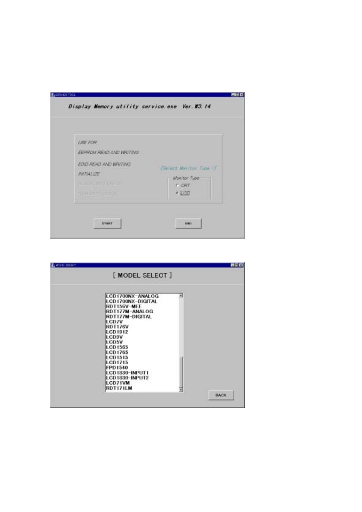
5.4 Operation
1) Connect the EDID data writing unit with jigs, etc.
2) Copy all the files of the service tool Ver. 3.14 (Parameter ver. 2.0-S14) in a proper directory.
3) Start [Service2.EXE] of the service tool Ver. 3.14.
4) When the screen as shown below appears, check to [LCD] of [Monitor Type] and press the [START]
button.
5) When the screen as shown below appears, adjust the cursor to [LCD71VM] and make a double click.
5-17

6) When the screen as shown below appears, check to [EDID_READ] and press the [OK] button.
7) When the screen as shown below appears, confirm that the correct data are displayed in the columns of
EDID DATA CONTENTS and Serial information.
If all the displayed data are [FF] or the like, or if the serial number is different from that of the
corresponding unit, then EDID data writing should be carried out.
8) When a screen of Item 6 is displayed by pressing the [BACK] button, check to [EDID_WRITE] and press
the [OK] button.
5-18

9) When the screen as shown below appears, examine the serial number of the unit, enter an input in the
column of [Input Serial No.] through the keyboard, and press the [Input OK] button.
Enter an input in the column of [.Year=> ] in manufactured year(A.D. four digits) and [Month=>] in
manufactured month through the keyboard, and press the [Input OK] button.
10) When the [WRITE EDID] button is pressed, writing of the EDID data only is carried out. Upon the
completion of correct writing, a display of [EDID Monitor Write OK] is presented in the column of
[STATUS].
5-19

11) Display “MONITOR INFORMATION” of the OSM, and confirm that the model name (LCD71VM) and
serial number have been correctly written.
12) Upon the normal completion of EDID data writing, press the [Exit] button to close the program.
5.5 EDID Data File
EDID date: LCD71VM.edi
0 1 2 3 4 5 6789ABCD E F
00 FF FF FF FF FF FF 00 38 A3 1C 66 01 01 01 01
00
Note1 Note
10
11 50 54 BF EF 80 71 4F 81 40 81 80 01 01 01 01
20
01 01 01 01 01 01 30 2A 00 98 51 00 2A 40 30 70
30
13 00 51 0E 11 00 00 1E 00 00 00 FD 00 38 4B 1F
40
51 0E 00 0A 20 20 20 20 20 20 00 00 00 FC 00 4E
50
45 43 20 4C 43 44 37 31 56 4D 0A 20 00 00 00 FF
60
00
70
01 03 08 22 1B 78 EA 2E E5 A4 57 4A 9C 25
2
Note3 Note3 Note3 Note3 Note3 Note3Note3Note3Note3Note3Note3Note3Note
3
00
Note
4
Note 1: address 10h Week of manufacture = Month of manufacture × 4
Note 2: address 11h Year of manufacture - 1990
Note 3: address 71h ~ 7Dh Serial Number (ASCII coded)
If less than 13 char, terminate with 0Ah and fill the rests with 20h.
Note 4: address 7Fh Checksum
The sum of entire 128 byte shall be equal to 00h.
5.6 EDID Write Protect Cancel Signal Timing
EDID write protect cancel
No. 0
Item Abbreviation EDID
Pixel frequency fc 28.32MHz
Horizontal frequency fh 31.469kHz
Line Time total Th 31.777us 900CLK
Horizontal active display Thd 25.422us 720CLK
Horizontal sync pulse Thp 3.813us 108CLK
Horizontal back porch Thb 1.907us 54CLK
Horizontal front porch Thf 0.636us 18CLK
Horizontal sync polarity NEG
Vertical Frequency fv 42.015Hz
Frame time total Tv 23.801ms 749H
Vertical active display Tvd 21.768ms 685H
Vertical sync pulse Tvp 0.095ms 3H
Vertical back porch Tvb 1.494ms 47H
Vertical front porch Tvf 0.445ms 14H
Vertical sync polarity NEG
5-20

Appendix Reference Signal Timings
5-21

No. 1 2
Item Abbreviation VGA 640x480 60Hz MAC 640x480
Pixel frequency fc 25.175MHz 30.24MHz
Horizontal frequency fh 31.47kHz 35.00kHz
Line Time total Th 31.78us 800CLK 28.57us 864CLK
Horizontal active display Thd 25.42us 640CLK 21.16us 640CLK
Horizontal sync pulse Thp 3.81us 96CLK 2.12us 64CLK
Horizontal back porch Thb 1.91us 48CLK 3.17us 96CLK
Horizontal front porch Thf 0.64us 16CLK 2.12us 64CLK
Horizontal sync polarity NEG NEG
Vertical Frequency fv 59.992Hz 66.66Hz
Frame time total Tv 16.68ms 525H 15.00ms 525H
Vertical active display Tvd 15.25ms 480H 13.71ms 480H
Vertical sync pulse Tvp 0.06ms 2H 0.09ms 3H
Vertical back porch Tvb 1.02ms 33H 1.11ms 39H
Vertical front porch Tvf 0.35ms 10H 0.09ms 3H
Vertical sync polarity NEG NEG
No. 3 4
Item Abbreviation VGA 640x480 72Hz VESA 640x480 75Hz
Pixel frequency fc 31.500MHz 31.500MHz
Horizontal frequency fh 37.86kHz 37.50kHz
Line Time total Th 26.41us 832CLK 26.67us 840CLK
Horizontal active display Thd 20.32us 640CLK 20.32us 640CLK
Horizontal sync pulse Thp 1.27us 40CLK 2.03us 64CLK
Horizontal back porch Thb 4.06us 128CLK 3.81us 120CLK
Horizontal front porch Thf 0.76us 24CLK 0.51us 16CLK
Horizontal sync polarity NEG NEG
Vertical Frequency fv 72.81Hz 75.00Hz
Frame time total Tv 13.73ms 520H 13.33ms 500H
Vertical active display Tvd 12.68ms 480H 12.80ms 480H
Vertical sync pulse Tvp 0.08ms 3H 0.08ms 3H
Vertical back porch Tvb 0.74ms 28H 0.43ms 16H
Vertical front porch Tvf 0.24ms 9H 0.03ms 1H
Vertical sync polarity NEG NEG
No. 5 6
Item Abbreviation VGA 720x350 70Hz VGA 720x400 70Hz
Pixel frequency fc 28.322MHz 28.322MHz
Horizontal frequency fh 31.47kHz 31.47kHz
Line Time total Th 31.78us 900CLK 31.78us 900CLK
Horizontal active display Thd 25.42us 720CLK 25.42us 720CLK
Horizontal sync pulse Thp 3.81us 108CLK 3.81us 108CLK
Horizontal back porch Thb 1.91us 54CLK 1.91us 54CLK
Horizontal front porch Thf 0.64us 18CLK 0.63us 18CLK
Horizontal sync polarity POS NEG
Vertical Frequency fv 70.087Hz 70.087Hz
Frame time total Tv 14.27ms 449H 14.27ms 449H
Vertical active display Tvd 11.12ms 350H 12.71ms 400H
Vertical sync pulse Tvp 0.06ms 2H 0.06ms 2H
Vertical back porch Tvb 1.91ms 60H 1.11ms 35H
Vertical front porch Tvf 1.18ms 37H 0.38ms 12H
Vertical sync polarity NEG POS
5-22

No. 7 8
Item Abbreviation VESA 800x600 56Hz VESA 800x600 60Hz
Pixel frequency fc 36.00MHz 40.00MHz
Horizontal frequency fh 35.16kHz 37.88kHz
Line Time total Th 28.44us 1024CLK 26.40us 1065CLK
Horizontal active display Thd 22.22us 800CLK 20.00us 800CLK
Horizontal sync pulse Thp 2.00us 72CLK 3.20us 128CLK
Horizontal back porch Thb 3.56us 128CLK 2.20us 88CLK
Horizontal front porch Thf 0.67us 24CLK 1.00us 40CLK
Horizontal sync polarity POS POS
Vertical Frequency fv 56.25Hz 60.32Hz
Frame time total Tv 17.78ms 625H 16.58ms 628H
Vertical active display Tvd 17.07ms 600H 15.84ms 600H
Vertical sync pulse Tvp 0.06ms 2H 0.11ms 4H
Vertical back porch Tvb 0.63ms 22H 0.61ms 23H
Vertical front porch Tvf 0.03ms 1H 0.03ms 1H
Vertical sync polarity POS POS
No. 9 10
Item Abbreviation VESA 800x600 72Hz VESA 800x600 75Hz
Pixel frequency fc 50.000MHz 49.500MHz
Horizontal frequency fh 48.08kHz 46.88kHz
Line Time total Th 20.80us 1040CLK 21.33us 1056CLK
Horizontal active display Thd 16.00us 800CLK 16.16us 800CLK
Horizontal sync pulse Thp 2.40us 120CLK 1.62us 80CLK
Horizontal back porch Thb 1.28us 64CLK 3.23us 160CLK
Horizontal front porch Thf 1.12us 56CLK 0.32us 16CLK
Horizontal sync polarity POS(/NEG) POS
Vertical Frequency fv 72.19Hz 75.00Hz
Frame time total Tv 13.85ms 666H 13.33ms 625H
Vertical active display Tvd 12.48ms 600H 12.80ms 600H
Vertical sync pulse Tvp 0.13ms 6H 0.06ms 3H
Vertical back porch Tvb 0.48ms 23H 0.45ms 21H
Vertical front porch Tvf 0.77ms 37H 0.02ms 1H
Vertical sync polarity POS(/NEG) POS
No. 11 12
Item Abbreviation MAC 832x624 VESA 1024x768 60Hz
Pixel frequency fc 57.28MHz 65.000MHz
Horizontal frequency fh 49.73kHz 48.35kHz
Line Time total Th 20.11us 1152CLK 20.68us 1344CLK
Horizontal active display Thd 14.52us 832CLK 15.75us 1024CLK
Horizontal sync pulse Thp 1.12us 64CLK 2.09us 136CLK
Horizontal back porch Thb 3.91us 224CLK 2.46us 160CLK
Horizontal front porch Thf 0.56us 32CLK 0.37us 24CLK
Horizontal sync polarity NEG NEG
Vertical Frequency fv 74.55Hz 60.00Hz
Frame time total Tv 13.41ms 667H 16.67ms 806H
Vertical active display Tvd 12.55ms 624H 15.88ms 768H
Vertical sync pulse Tvp 0.06ms 3H 0.12ms 6H
Vertical back porch Tvb 0.78ms 39H 0.60ms 29H
Vertical front porch Tvf 0.02ms 1H 0.06ms 3H
Vertical sync polarity NEG NEG
5-23

No. 13 14
Item Abbreviation VESA 1024x768 70Hz VESA 1024x768 75Hz
Pixel frequency fc 75.000MHz 78.75MHz
Horizontal frequency fh 56.48kHz 60.02kHz
Line Time total Th 17.71us 1328CLK 16.66us 1312CLK
Horizontal active display Thd 13.65us 1024CLK 13.00us 1024CLK
Horizontal sync pulse Thp 1.81us 136CLK 1.22us 96CLK
Horizontal back porch Thb 1.92us 144CLK 2.24us 176CLK
Horizontal front porch Thf 0.32us 24CLK 0.20us 16CLK
Horizontal sync polarity NEG POS
Vertical Frequency fv 70.07Hz 75.03Hz
Frame time total Tv 14.27ms 806H 13.33ms 800H
Vertical active display Tvd 13.60ms 768H 12.80ms 768H
Vertical sync pulse Tvp 0.11ms 6H 0.05ms 3H
Vertical back porch Tvb 0.51ms 29H 0.47ms 28H
Vertical front porch Tvf 0.05ms 3H 0.02ms 1H
Vertical sync polarity NEG POS
No. 15 16
Item Abbreviation MAC 1152x870 75Hz VESA 1280x960 60Hz
Pixel frequency fc 100.00MHz 108.00MHz
Horizontal frequency fh 68.82kHz 60.00kHz
Line Time total Th 14.56us 1456CLK 16.67us 1800CLK
Horizontal active display Thd 11.52us 1152CLK 11.85us 1280CLK
Horizontal sync pulse Thp 1.28us 128CK 1.04us 112CLK
Horizontal back porch Thb 1.44us 144CLK 2.89us 312CLK
Horizontal front porch Thf 0.32us 32CLk 0.89us 96CLK
Horizontal sync polarity NEG POS
Vertical Frequency fv 75.06Hz 60.00Hz
Frame time total Tv 13.32ms 915H 16.67ms 1000H
Vertical active display Tvd 12.67ms 870H 16.0ms 960H
Vertical sync pulse Tvp 0.04ms 3H 0.05ms 3H
Vertical back porch Tvb 0.57ms 39H 0.60ms 36H
Vertical front porch Tvf 0.04ms 3H 0.017ms 1H
Vertical sync polarity NEG POS
No. 17 18
Item Abbreviation VESA 1280x960 75Hz VESA 1280x1024 60Hz
Pixel frequency fc 129.60MHz 108.00MHz
Horizontal frequency fh 75.000kHz 63.981kHz
Line Time total Th 13.333us 1728CLK 15.63us 1688CLK
Horizontal active display Thd 9.877us 1280CLK 11.85us 1280CLK
Horizontal sync pulse Thp 0.988us 128CLK 1.04us 112CLK
Horizontal back porch Thb 1.975us 256CLK 2.30us 248CLK
Horizontal front porch Thf 0.494us 64CLK 0.44us 48CLK
Horizontal sync polarity POS POS
Vertical Frequency fv 75.000Hz 60.02Hz
Frame time total Tv 13.333ms 1000H 16.67ms 1066H
Vertical active display Tvd 12.800ms 960H 16.00ms 1024H
Vertical sync pulse Tvp 0.040ms 3H 0.05ms 3H
Vertical back porch Tvb 0.480ms 36H 0.59ms 38H
Vertical front porch Tvf 0.013ms 1H 0.02ms 1H
Vertical sync polarity POS POS
5-24

MODE
No. 19
Item Abbreviation VESA 1280x1024 75Hz
Pixel frequency fc 135.00MHz
Horizontal frequency fh 79.98kHz
Line Time total Th 12.50us 1688CLK
Horizontal active display Thd 9.48us 1280CLK
Horizontal sync pulse Thp 1.07us 144CLK
Horizontal back porch Thb 1.84us 248CLK
Horizontal front porch Thf 0.12us 16CLK
Horizontal sync polarity POS
Vertical Frequency fv 75.03Hz
Frame time total Tv 13.33ms 1066H
Vertical active display Tvd 12.80ms 1024H
Vertical sync pulse Tvp 0.04ms 3H
Vertical back porch Tvb 0.48us 38H
Vertical front porch Tvf 0.01ms 1H
Vertical sync polarity POS
5-25

TROUBLE SHOOTING
TABLE OF CONTENTS
1. No Display on Screen (Screen is Black, LED is Amber) -------------------------------------------- 6-2
2. No Display on Screen (Screen is Black, LED is Green) -------------------------------------------- 6-3
3. Checking the Back Light Unit ------------------------------------------------------------------------------ 6-5
4. Abnormal Screen --------------------------------------------------------------------------------------------- 6-6
5. Abnormal Plug and Play Operation ---------------------------------------------------------------------- 6-7
6. Checking the Sync Signal Interface Circuit ------------------------------------------------------------ 6-8
6.1 Checking the Horizontal Sync Pulse Control Circuit ----------------------------------------------- 6-8
6.2 Checking the Vertical Sync Pulse Control Circuit --------------------------------------------------- 6-9
7. Checking the Scaling IC Movement --------------------------------------------------------------------- 6-10
Page
8. No Power On -------------------------------------------------------------------------------------------------- 6-11
9. Checking the Audio Operation ---------------------------------------------------------------------------- 6-12
6-1

1. No Display on Screen (Screen is Black, LED is Amber)
Y
Does OSM display when you
push “AUTO/RESET”, “+”, ”-”,
“SELECT” button.
NO
Proceed section 2 “Nothing
display on screen”.
ES
When a signal isn't being inputted, it is indicated with "NO SIGNAL".
It is indicated with "OUT OF RANGE" at the time of the frequency that it
over spec.timing.
Check if the sync signal from Computer is output
and if the video cable is connected normally.
NG
OK
Proceed section 7 “Checking the Scaling IC
movement”.
Input the sync signal of computer,
or change the cable.
6-2

2. No Displays on Screen (Screen is Black, LED is Green)
Does computer output RGB
video signals?
Check OSM menu is displayed on screen
when you push the” AUTO/RESET”,
“+”, ”-”, ”SELECT” Key.
Proceed section 4
“Abnormal screen “.
Is backlight lit?
NG
OK
NG
OK
NG
OK
Refer to section 3
“Checking the BackLight Unit.
Check the video cable for failure.
Check the host for output signal with all black only.
1) Change pattern of video signal output on the host.
2) Reconnect the video cable.
3) Change the video cable.
Check if the LCD video signal cable is connected
between the MAIN board and LCD module.
NG
OK
Next page
Failure point
The cable is disconnected.
6-3

Continue
Is 5V voltage provided to pin1,pin 2 and pin 3 of S404
in MAIN board.
NG
OK
Failure point
Check Q405and U409.
Check the data signal output on U405
LVDS-O, LVDS-E pin?
NG
Failure point
Printed wire broke
between U405, S404 line.
OK
Failure point
U405 failure.
6-4

3. Checking the Back Light Unit
t
Check 5V voltage provided of
Smart Power BD CN21 pin 2
and pin 3.
OK
Check the ON/FF signal of
equal “H” at CN51 pin6 in Smar
Power BD?
OK
Is 12V voltage provided from
Smart Power BD ?
Check F101 open.
NG
NG
NG
OK
Failure point
Inverter Area of Smart
Power BD failure.
Smart power BD: Combined board of power and inverter circuits.
Failure point
Power Area of Smart
Power Board failure.
Failure point
1. U405 failure (Main BD)
2. Printed wire or parts broke between U405 pin 41 to CN51 pin 6.
Failure point
F101 failure.
6-5
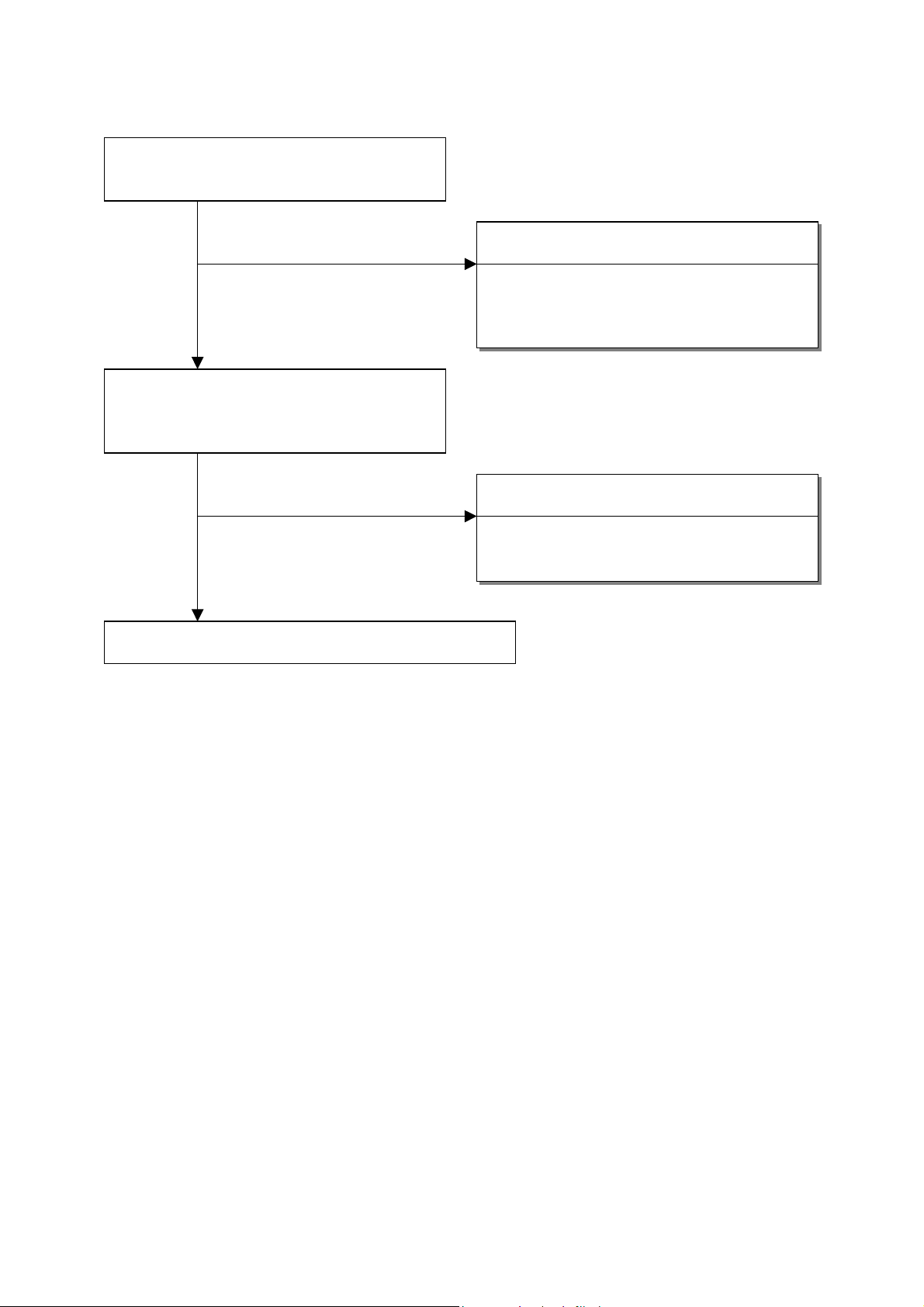
4. Abnormal Screen
r
Check the R, G, B video signal from compute
input on D-Sub R,G,B connector.
OK
Check the R,B,G input signals on U405 pins
135, 131, 127,respectively that their level is
0.7Vp-p typical.
NG
Failure point
1) No R, G and B video signal output from host
computer. Check computer.
2) Video signal cable disconnection.
OK
Proceed section 7 “Checking the scaling IC movement”.
NG
Failure point
Printed wire broke between D-Sub(R,G,B) and
U405 pins 135,131,127.
6-6

5. Abnormal Plug and Play Operation
Abnormal DDC2B
Confirm clock and serial data on U401 pins 5, 6.
OK
1) The host machine isn't communicating in DDC2B mode.
2) The video cable may have failed or may not to have
connections for DDC.
3) Between U401 pins 5,6 and P401 pins 12,15 may have
failed.
4) Cable failure.
NG
Failure point
Failure point
U401 failure.
6-7

6. Checking the Sync Signal Interface Circuit
t
6.1 Checking the Horizontal Sync Pulse Control Circuit
Check the horizontal sync signal on U402 pin 1 a
TTL level.
OK
Check the horizontal sync signal on U405 pin 101 a
TTL level.
OK
Procees section 7 “Checking the scaling IC
movement”.
NG
NG
Failure point
1) No separate sync or sync output by (Confirm
the host, output the sync signal.)
2) Video cable may have failed.
3) Printed wire broke between P401 pin 13 and
U402 pin 1.
4) B401 or R415. open.
5) U402 failure.
Failure point
U405 failure.
6-8

6.2 Checking the Vertical Sync Pulse Control Circuit
Check the vertical sync signal on U402 pin 5
at TTL level.
NG
OK
1) No separate sync output signal from the host.
2) Video cable may have failed.
3) Printed wire broke between P401 pin 14 and
4) B402 or R16 open.
5) U402 failure
Proceed section 7 “Checking the scaling IC
movement”.
Failure point
(Check the host.)
U402 pin 5.
6-9

7. Checking the Scaling IC Movement
Is there +3.3V supply on U405 pins 14, 30, 90, 104, 106, 108, 110, 113,115, 124, 128, 132,
136, 143, 157. Is there +2.5V SUPPLY ON U405 pins 20, 43, 46, 59, 61, 63, 74, 77, 79, 98,
117, 119, 138.
OK
Is 14.318M Hz clock input to U405 pins 102,
103 at TTL level?
OK
NG
Proceed section 8 "No Power On".
NG
Is 14.318M Hz clock output from X401 at TTL level?
OK
Failure point
X401 failure
U405 failure.
6-10

8. No Power On
Check the +5V power provided from Power Board.
OK
Check both 3.3V and 2.5V power from U404.
OK
NG
NG
U405 failure.
Failure point
Power Board failure.
Failure point
Check U404.
6-11

9. Checking the Audio Operation
Is there Audio ON, Volume is tuned to Max when enter OSD function ,and Audio input signal.
Is there +5V supply on U501 pins 6, 16, 27.
OK
Check Audio_Volume signal of equal” H ” at U501 pin 7.
OK
Check STBY. Is there +5V supply on U501 pin 2.
OK
Check MUTE. Is there 0V on U501 pin 5.
OK
Failure point
NG
NG
NG
NG
Failure point
L501 open.
Failure point
Check the trace from U501 pin 7 to U405 pin 24.
Failure point
1. Check software.
2. U405 failure.
Failure point
1. Check software.
2. U405 failure.
U501 failure.
6-12
 Loading...