


E
XPRESS
■■■■■■■
■■■■■■■
■■■■■■■
■■■■■■■
■■■■■■■
■■■■■■■
5800/120Rb-1
()
User’s Guide
■■■■■■■
■■■■■■■
■■■■■■■
■■■■■■■
■■■■■■■
■■■■■■■
■■■■■■■
■■■■■■■

xxx

E
XPRESS
■■■■■■■
■■■■■■■
■■■■■■■
■■■■■■■
■■■■■■■
■■■■■■■
5800/120Rb-1
()
User’s Guide
■■■■■■■
■■■■■■■
■■■■■■■
■■■■■■■
■■■■■■■
■■■■■■■
■■■■■■■
■■■■■■■

Proprietary Notice and Liability Disclaimer
The information disclosed in this document, including all designs and related materials, is
the valuable property of NEC Computers Inc. and/or its licensors. NEC Computers Inc.
and/or its licensors, as appropriate, reserve all patent, copyright and other proprietary rights
to this document, including all design, manufacturing, reproduction, use, and sales rights
thereto, except to the extent said rights are expressly granted to others.
The NEC Computers Inc. product(s) discussed in this document are warranted in
accordance with the terms of the Warranty Statement accompanying each product.
However, actual performance of each product is dependent upon factors such as system
configuration, customer data, and operator control. Since implementation by customers of
each product may vary, the suitability of specific product configurations and applications
must be determined by the customer and is not warranted by NEC Computers Inc.
To allow for design and specification improvements, the information in this document is
subject to change at any time, without notice. Reproduction of this document or portions
thereof without prior written approval of NEC Computers Inc. is prohibited.
Trademarks
INTEL is a registered trademark of Intel Corporation.
MS-DOS is a registered trademark of Microsoft Corporation.
Pentium is a registered trademark of Intel Corporation.
All other product, brand, or trade names used in this publication are the trademarks or registered
trademarks of their respective trademark owners.
PN: 456-01578-000 January 2002
Copyright 2002
NEC Computers Inc.
15 Business Park Way
Sacramento, CA 95828
All Rights Reserved

CONTENTS
Using This Guide ............................................................................................................... vii
Text Conventions ..........................................................................................................................viii
Safety Indications and Symbols ...............................................................................................viii
Related Documents.....................................................................................................................ix
Safety Notices..............................................................................................................................x
Care and Handling.....................................................................................................................xii
System Overview .............................................................................................................. 1-1
Overview.......................................................................................................................................1-2
Front View with Front Bezel Closed ........................................................................................1-3
Front View with Front Bezel Removed....................................................................................1-4
Rear View .................................................................................................................................1-5
Internal View ............................................................................................................................1-7
System Board ...........................................................................................................................1-8
Status Indicators............................................................................................................................1-9
POWER Lamp..........................................................................................................................1-9
STATUS Lamp .........................................................................................................................1-9
DISK ACCESS Lamp ............................................................................................................1-11
ACT Lamp..............................................................................................................................1-11
Disk Access Lamp..................................................................................................................1-11
Hard Disk Lamp .....................................................................................................................1-12
LAN Connector Lamps ..........................................................................................................1-13
Standard Features........................................................................................................................1-14
Power Supply .........................................................................................................................1-15
Peripheral Bays.......................................................................................................................1-15
System Cooling ......................................................................................................................1-15
SAF-TE Logic ............................................................................................................................1-16
System Board Features ...............................................................................................................1-16
Processor ................................................................................................................................1-16
Memory ..................................................................................................................................1-16
PCI Riser Slots .......................................................................................................................1-17
Video ......................................................................................................................................1-17
SCSI Controller ......................................................................................................................1-17
Network Controller.................................................................................................................1-18
Network Teaming Features.....................................................................................................1-19
Keyboard and Mouse..............................................................................................................1-21
RJ-45 Serial Port ....................................................................................................................1-21
ACPI.......................................................................................................................................1-21
System Board Management Controller (BMC)......................................................................1-22
Degradation Feature....................................................................................................................1-23
Remote Power-On Feature (Wake On LAN) ..............................................................................1-23
AC-LINK Feature.......................................................................................................................1-23
System Security ..........................................................................................................................1-24
Security with Mechanical Locks and Monitoring...................................................................1-24
Software Locks via the BIOS Setup Utility............................................................................1-24
EXPRESSBUILDER..................................................................................................................1-28
ESMPRO ....................................................................................................................................1-29
Off-line Maintenance Utility.......................................................................................................1-29
System Diagnostic Utility...........................................................................................................1-29
Management Workstation Application (MWA).........................................................................1-29
iii

iv
Using Your Server...................................................................................................................... 1-30
Front Bezel ............................................................................................................................ 1-30
POWER Switch..................................................................................................................... 1-32
Identification of Servers ~ UID Switch ~.............................................................................. 1-37
Floppy Disk Drive ................................................................................................................. 1-38
CD-ROM Drive ..................................................................................................................... 1-40
Chapter 2 Setting Up Your System ................................................................................2-1
Setup Flow ................................................................................................................................... 2-2
Selecting a Site............................................................................................................................. 2-3
Installation ............................................................................................................................... 2-3
Rack Installation...................................................................................................................... 2-3
Unpacking the System ................................................................................................................. 2-5
Assembling the Rack-mount System ........................................................................................... 2-6
Restricted Access Location......................................................................................................2-7
ESD Precaution ....................................................................................................................... 2-7
Checking Components.............................................................................................................2-7
Required Tools......................................................................................................................... 2-7
Installation Procedure for NEC Rack or Vendor’s Rack.......................................................... 2-8
Removing the Server from the Rack Assembly..................................................................... 2-14
Connecting Peripheral Devices.................................................................................................. 2-16
Connection to Serial Ports ..................................................................................................... 2-18
Connecting the Power Cord.......................................................................................................2-21
Turning On the Server................................................................................................................ 2-23
Installing the Operating System.................................................................................................2-25
Installing Utilities....................................................................................................................... 2-25
Making Backup Copies of System Information......................................................................... 2-26
Chapter 3 Configuring Your System.............................................................................. 3-1
System BIOS ~ SETUP ~ ............................................................................................................ 3-1
Starting SETUP Utility............................................................................................................ 3-2
Description on On-Screen Items and Key Usage .................................................................... 3-3
Configuration Examples..........................................................................................................3-4
Menu and Parameter Descriptions........................................................................................... 3-9
SCSI BIOS ~ SCSISelect ~........................................................................................................ 3-31
Using SCSISelect Utility ....................................................................................................... 3-31
Configuring SCSI Controller on System Board .................................................................... 3-31
Configuring SCSI Controller on Optional Board .................................................................. 3-40
Configuring system Board Jumpers ........................................................................................... 3-41
Chapter 4 Installing the Operating System ................................................................... 4-1
About Express Setup.................................................................................................................... 4-2
Microsoft Windows 2000............................................................................................................. 4-4
Installation Notice.................................................................................................................... 4-4
Setup Flow............................................................................................................................... 4-8
Installing and Configuring Device Drivers............................................................................ 4-13
Setup for Problem Resolution................................................................................................ 4-16
Installing Maintenance Utilities............................................................................................. 4-19
Updating the System - Applying Service Pack - ................................................................... 4-20
Making Backup Copies of System Information..................................................................... 4-20
Microsoft Windows NT 4.0 ....................................................................................................... 4-21
Installation Notice.................................................................................................................. 4-21
Setup Flow............................................................................................................................. 4-24
Installing Windows NT 4.0.................................................................................................... 4-25

Installing and Setting Device Drivers.....................................................................................4-29
Setup for Problem Resolution.................................................................................................4-31
Installing Maintenance Utilities..............................................................................................4-36
Updating the System - Applying Service Pack - ....................................................................4-36
Making Backup Copies of System Information .....................................................................4-37
Novell NetWare 5.0 ....................................................................................................................4-38
Required Diskettes..................................................................................................................4-38
Installation Assumption..........................................................................................................4-38
Preparation .............................................................................................................................4-39
Installing the Novell NetWare v5.0 Network Operating System............................................4-43
Restarting the Server ..............................................................................................................4-45
Backing Up the Server............................................................................................................4-45
SCO OpenServer 5.0.6................................................................................................................4-46
Required Diskettes..................................................................................................................4-46
Preparation .............................................................................................................................4-47
Installing Optional Hardware .................................................................................................4-48
Installing and Configuring System Software..........................................................................4-49
Chapter 5 Maintenance ................................................................................................... 5-1
Making Backup Copies.................................................................................................................5-1
Cleaning........................................................................................................................................5-2
Cleaning the Server ..................................................................................................................5-3
Cleaning the Interior.................................................................................................................5-4
Cleaning the Keyboard/Mouse.................................................................................................5-5
Cleaning CD-ROM...................................................................................................................5-6
System Diagnostics.......................................................................................................................5-7
Test Items .................................................................................................................................5-7
Starting and Ending the System Diagnostics............................................................................5-8
Relocating/Storing the Server.....................................................................................................5-10
v
Chapter 6 Troubleshooting............................................................................................. 6-1
System Viewers.............................................................................................................................6-2
Lamps ...........................................................................................................................................6-3
Error Messages .............................................................................................................................6-4
Error Messages after Power-on ................................................................................................6-4
POST Error Messages ..............................................................................................................6-5
Beep Codes.............................................................................................................................6-10
Solving Problems........................................................................................................................ 6-11
Problems with the Server........................................................................................................6-11
Problems with EXPRESSBUILDER......................................................................................6-20
Problems with Express Setup .................................................................................................6-21
Error Message during Disk Array Configuration ...................................................................6-26
Problems with Master Control Menu .....................................................................................6-26
Problems with Configuration Diskette Creator ......................................................................6-27
Collecting Event Log..................................................................................................................6-28
Windows 2000........................................................................................................................6-28
Windows NT 4.0 ....................................................................................................................6-29
Collect Configuration Information..............................................................................................6-30
Windows 2000........................................................................................................................6-30
Windows NT 4.0 ....................................................................................................................6-30
Collecting Dr. Watson Diagnostic Information...........................................................................6-31
Memory Dump............................................................................................................................6-31
Preparing for Memory Dumping.................................................................................................6-31
Saving the Dump File.............................................................................................................6-32
Backup IPMI Information ......................................................................................................6-33

vi
Recovery for Windows 2000/Windows NT System .................................................................. 6-34
Off-Line Maintenance Utility ....................................................................................................6-39
Starting the Off-line Maintenance Utility.............................................................................. 6-40
Features of Off-line Maintenance Utility............................................................................... 6-41
Resetting the Server ................................................................................................................... 6-42
Forced Shutdown ....................................................................................................................... 6-42
Chapter 7 Upgrading Your Server .................................................................................. 7-1
Safety Notes................................................................................................................................. 7-2
Anti-static Measures .................................................................................................................... 7-3
Preparing Your System for Upgrade ............................................................................................ 7-4
Device Installation or Removal Procedure .................................................................................. 7-5
Hard Disk Drive....................................................................................................................... 7-5
Server ~ Pull-out from the Rack ~......................................................................................... 7-13
Top Cover .............................................................................................................................. 7-15
DIMM.................................................................................................................................... 7-17
Processor (CPU) .................................................................................................................... 7-22
PCI Board.............................................................................................................................. 7-31
Disk Array Controller Board................................................................................................. 7-37
Appendix A Specifications .............................................................................................A-1
Appendix B Interrupt Requests (IRQs) ......................................................................... B-1
Appendix C Installing and Configuring Windows 2000 and Windows NT 4.0 .......... C-1
Windows 2000 .............................................................................................................................C-1
Device Drivers......................................................................................................................... C-1
Installation Assumption........................................................................................................... C-2
Preparation...............................................................................................................................C-3
Installing Microsoft Windows
®
2000 Operating System......................................................... C-4
Installing LAN Adapters.........................................................................................................C-5
Driver Installation for the ATI RAGE XL Display Adapter....................................................C-5
Windows NT 4.0..........................................................................................................................C-6
Device Drivers......................................................................................................................... C-6
Configuring RAID...................................................................................................................C-7
Installing Microsoft Windows
®
NT 4.0 Operating System......................................................C-7
Installing LAN Adapter Drivers .............................................................................................C-8
Driver Installation for the ATI RAGE XL Display Adapter....................................................C-9
Appendix D Equipment Log........................................................................................... D-1
Hardware .................................................................................................................................D-1
Software...................................................................................................................................D-3

Using This Guide iii
Using This Guide
Welcome to the NEC Express5800/120Rb-1 server User’s Guide. This User's Guide provides a
quick reference to information about your server system. Its goal is to familiarize you with your
system and the tasks necessary for system configuring and upgrading.
This guide contains the following information:
Chapter 1, “System Overview” provides all the information necessary to use the server,
!
including a description your system’s major system components. See this chapter to
familiarize yourself with your system and how to use it.
Chapter 2, “Setting Up Your System” tells you how to select a site, unpack the system,
!
assemble the rack-mount subsystem, make cable connections, and power on your
system.
Chapter 3, “Configuring Your System” tells you how to configure the system and
!
provides instructions for running the BIOS Setup Utility and the Adaptec Configuration
Utility, which is used to configure SCSI devices in your system. This chapter also
provides information on system board jumper settings.
Chapter 4, "Installing the Operating System" describes how to install the operating
!
system.
Chapter 5. "Maintenance" provides you with all the information necessary to maintain
!
successful operation of the server. This chapter also includes a description on relocating
and storing the server.
Chapter 6, “Troubleshooting” contains helpful information for solving problems that
!
might occur with your system.
Chapter 7, “Upgrading Your System” provides you with instructions for upgrading your
!
system with an additional processor, optional memory, options cards, and peripheral
devices.
Appendix A, “Technical Specifications” provides specifications for your server system.
!
Appendix B, “Interrupt Request/PCI IRQ Device/I/O Port Address Assignments"
!
provides the Interrupt Requests (IRQs), PCI IRQ device, and I/O port addresses that are
assigned by the factory for this system. These values can be used for reference when
installing an optional device.
Appendix C, “Installing Windows 2000/Windows NT 4.0" describes how to install
!
Microsoft Windows 2000 and Microsoft Windows NT 4.0 without using Express Setup.
Appendix D, “Equipment Log" provides a table for documenting your system configuration
!
and future updates you may make to your system.
“Glossary” defines the standard acronyms and technical terms used in this manual.
!

iv Using This Guide
Text Conventions
This guide uses the following text conventions.
IMPORTANT:
NOTE:
Items that are mandatory or require attention when using the server
Notes give important information about the material being described.
Safety Indications and Symbols
Safety
Follow the instructions in this User’s Guide to use your server safely.
In this User’s Guide a "WARNING" or "CAUTION" is used to indicate a degree of danger. These
terms are defined as follows:
WARNING
CAUTION
Symbols
Precautions and notices against hazards are represented with one of the following three symbols:
This symbol indicates the presence of a hazard if the instruction is ignored.
An image in the symbol illustrates the hazard type. (Attention)
Warnings alert you to situations that could result in serious
personal injury or loss of life.
Indicates the presence of a hazard that may cause minor
personal injury, including burns, or property damage if the
instruction is ignored.
Attentions
This symbol indicates prohibited actions. An image in the symbol illustrates
a particular prohibited action. (Prohibited Action)
This symbol indicates mandatory actions. An image in the symbol illustrates
a mandatory action to avoid a particular hazard. (Mandatory Action)
Indicates that improper use may cause an electric shock.
Indicates that improper use may cause personal injury.
Indicates that improper use may cause fingers to be caught.
Indicates that improper use may cause fumes or fire.
Indicates a general notice or warning that cannot be specifically identified.
Indicates that improper use may cause loss of eyesight due to laser beam.

Using This Guide v
Prohibited Actions
Indicates a general prohibited action that cannot be specifically identified.
Do not disassemble, repair, or modify the server. Otherwise, an electric
shock or fire may be caused.
Mandatory Action
Unplug the power cord of the server. Otherwise, an electric shock or fire
may be caused.
Indicates a mandatory action that cannot be specifically identified. Make
sure to follow the instruction.
Related Documents
In addition to this guide, the following system documentation is included with your server either as
electronic files on E
XPRESSBUILDER
or as paper copy shipped with your server.
System Release Notes
!
Release Notes provide you with the latest information about your system. This
information was not available to be included in your user's guide at the time it was
developed and released.
Getting Started Sheet
!
The Getting Started Sheet provides several easy-to-follow steps to become familiar with
your server documentation and to complete your installation successfully.

vi Using This Guide
Safety Notices
Caution: To reduce the risk of electric shock which could cause personal injury, follow
!
all safety notices. The symbols shown are used in your documentation and on your
equipment to indicate safety hazards.
Warning: Lithium batteries can be dangerous. Improper handling of lithium batteries
!
may result in an explosion. Dispose of lithium batteries as required by local ordinance or
as normal waste if no local ordinance exists.
Warning: The detachable power supply cord is intended to serve as the disconnect
!
device.
Warning: This equipment has a 3-wire, grounded power cord. To prevent electrical
!
hazards, do not remove or defeat the ground prong on the power cord. Replace the
power cord if it gets damaged. Contact your dealer for an exact replacement.
Warning: The DC push-button on/off switch on the front panel does not turn off the
!
system AC power. Also, +5vdc is present on the system board whenever the AC power
cord is connected between the system and an AC outlet. Before doing the procedures in
this manual, make sure that your system is powered off and unplug the AC power cord
from the back of the chassis. Failure to disconnect power before opening your system
can result in personal injury and equipment damage.
!
In the U.S.A. and Canada, the power cord must be a UL-listed detachable power cord (in
Canada, CSA-certified), type ST or SJT, 16 AWG, 3-conductor, provided with a molded-on
NEMA type 5-15 P plug cap at one end and a molded-on cord connector body at the other
end. The cord length must not exceed 9 feet (2.7 meters).
Outside the U.S.A. and Canada, the plug must be rated for 250 VAC, 10 amp minimum,
and must display an international agency approval marking. The cord must be suitable for
use in the end-user country. Consult your dealer or the local electrical authorities if you are
unsure of the type of power cord to use in your country. The voltage change occurs via a
switch in the power supply.
Warning: Under no circumstances should the user attempt to disassemble the power
!
supply. The power supply has no user-replaceable parts. Inside the power supply are
hazardous voltages that can cause serious personal injury. A defective power supply
must be returned to your dealer.

Using This Guide vii
Safety Notices for Users Outside of the U.S.A. and Canada
PELV (Protected Extra-Low Voltage) Integrity: To ensure the extra-low voltage
!
integrity of the equipment, connect only equipment with mains-protected electricallycompatible circuits to the external ports.
Remote Earths: To prevent electrical shock, connect all local (individual office)
!
computers and computer support equipment to the same electrical circuit of the building
wiring. If you are unsure, check the building wiring to avoid remote earth conditions.
Earth Bonding: For safe operation, only connect the equipment to a building supply
!
that is in accordance with current wiring regulations in your country. In the U.K., those
regulations are the IEE.

viii Using This Guide
Care and Handling
Use the following guidelines to properly handle and care for your system.
Protect the system from extremely low or high temperatures. Let
the system warm (or cool) to room temperature before using it.
Keep the system away from magnetic forces.
Keep the system dry. Do not wash the system with a wet cloth or
pour fluid into it.
Protect the system from being bumped or dropped.
Check the system for condensation. If condensation exists, allow it
to evaporate before powering on the system.
Keep the system away from dust, sand, and dirt.

Chapter 1
System Overview
This chapter provides information that you should familiarize yourself with before using the
server. It includes names and functions of the components and features of the server.

1-2 System Overview
OVERVIEW
Your server is a modular multiprocessing server based on the Intel Pentium® III
microprocessors. It is a solid performer and offers the latest technology. The combination of
compute performance, memory capacity, and integrated I/O provides a high performance
environment for many server market applications. These range from large corporations
supporting remote offices to small companies looking to obtain basic connectivity capability such
as file and print services, e-mail, web access, web site server, etc.
Your server is a rack-mount system that conveniently installs into a standard EIA 19-inch rack
assembly.
Your server includes a 3.5-inch diskette drive, a CD-ROM drive and three hot-swap SCSI hard
disk drive bays. The hot-swap SCSI hard disk drive bays support up to three 1.0-inch SCSI hard
disk drives that can be swapped in or out of the system without powering it down, if RAID
functionality is configured in the system.
As application requirements increase, you can expand your server with an additional processor,
additional memory, add-in boards, and hard disk drives.

Front View with Front Bezel Closed
The following figure shows the location of the front system features.
System Overview 1-3
3
1 2
1 Front bezel
The front bezel is a cover protecting and providing security for the front controls and devices
in the server. A security key is provided to lock the cover.
2Keylock
Insert the security key into the key slot of the keylock when unlocking the front bezel.
3 POWER/SLEEP lamp (green)
This lamp turns green when the power is turned on.
4 STATUS lamp (green/amber)
This lamp indicates the server status. The lamp is green during normal operation. The lamp
turns amber color or flashes when the server enters an abnormal state.
5 DISK ACCESS lamp (green/amber)
This lamp is green during access to the internal hard disks. The lamp turns amber color
when one of the internal hard disks fails.
6 ACT lamp (green)
This lamp is on while the system is connected to the network. Icon number "1" indicates LAN
port 1, and Icon number "2" indicates LAN port 2.
7 UID lamp (blue)
This lamp goes on when the UID switch is pressed or when software issues a command.
4
5
6-1 6-2 7

1-4 System Overview
Front View with Front Bezel Removed
-1
4-1
3
3-2
5
-3
3
See 3 through 7 on
the previous page.
-2
4
1
2
1 Thumbscrews (one on each side of the front panel)
The thumbscrews secure the server to the rack.
2 Handles (one on each side of the front panel)
The handles are used to grasp the server unit when sliding it in and out of the rack.
3 CD-ROM drive
3-1 Disk access lamp
3-2 CD tray eject button
3-3 Emergency hole
4 Hard disk bays
Each number following the bold-faced number indicates the SCSI ID. Dummy trays are
mounted in the bays, except 4-1 in the standard system configuration.
5 DISK lamp (green/amber)
Each hard disk lamp is green when the drive is being accessed. The lamp turns amber color
when the hard disk fails. The lamp flashes between green and amber during the build
process (in disk array configuration only).
6 3.5-inch floppy disk drive
6-1 Disk access lamp
-2 Disk slot
6
-3 Eject button
6
7 Front serial port 2 connector
Connect a serial interface device to this connector. The server jumper setting needs to be
changed depending on the device to be connected. This connector is capped to prevent
accidentally connecting a RJ-45 network cable connector to this serial port connector.
8 USB connectors (2 ports)
Connect only USB compliant devices to these connectors. (Windows NT 4.0 requires a
compliant driver.)
9 POWER switch
Press this switch to turn the power on/off. Pressing the switch once turns the power on, and
the POWER/SLEEP lamp goes on. Pressing it again turns the power off. Pressing the
switch for 4 seconds or more turns the power off automatically.
10 UID (unit ID) switch
Press this switch to turn the UID lamps on/off. There is a UID lamp located on the front and
rear panels of the server.
11 DUMP switch
Press this switch to dump memory.
6-1
6-3
6-2
4-3
10
7
11
98
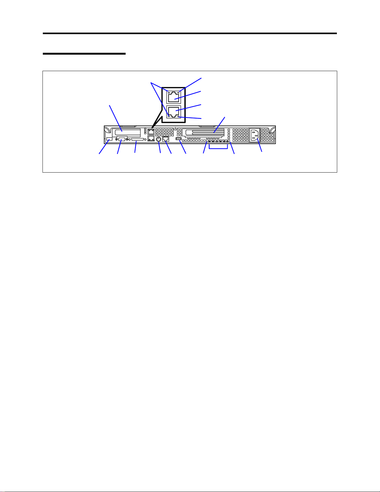
Rear View
System Overview 1-5
6
2
134 89 11113
1 USB connector
Connect a device compliant USB interface to this connector. (Windows NT 4.0 requires a
compliant driver.)
2 Low-profile PCI board extension slot
Mount a low-profile PCI board into this slot. The slot number is 1C.
3 Monitor connector
Connect a monitor display unit to this connector.
4 SCSI connector
Connect an external SCSI device to this connector.
5 100BASE-TX/10BASE-T connectors
Connect LAN network systems to these connectors.
The number "1" following bold-faced number 5 indicates LAN port 1, and the number "2"
indicates LAN port 2.
To remove a connector in LAN port 1 use a flat-tip screwdriver to push the locking tab on the
connector. Use care not to damage the LAN port or any other ports with screwdriver.
6 LINK/ACT lamp (green)
This lamp indicates access status of the LAN.
7 Speed lamp (amber)
This lamp indicates the transmission speed of the LAN.
8 Mouse/keyboard connector
Connect the mouse and keyboard to the connector using the PS2 "Y" cable.
9 Rear serial port 2 connector
Connect a serial interface device to this connector. The server setting needs to be changed
depending on the device to be connected. This connector is capped to prevent accidentally
connecting a RJ-45 network cable connector to this serial port connector.
10 Full-height PCI board extension slots
Mount a full-height PCI board in this slot. The slot number is 1B.
7
5-2
5-1
10
7
12
14

1-6 System Overview
11 STATUS lamp (green/amber) (on the real panel)
This lamp indicates the server status. The lamp is green color during normal operation. The
lamp turns amber color or flashes when the server enters an abnormal state.
12 POST lamps
The POST lamps are when POST is running and checking the system.
13 UID lamp (blue)
This lamp goes on when the UID switch is pressed or when a software command is issued.
14 AC inlet
Connect the power cord to this socket.
IMPORTANT:
The "100BASE-TX/10BASE-T connector" (Feature 5
above) and the "serial port 2 connector" (Feature 9 above) are the same
size and shape. Be careful when connecting a cable to either one of these
connectors in order to prevent accidentally connecting a RJ-45 network
cable connector to a serial port connector or vice versa.

Internal View
2-1
System Overview 1-7
8-1 to 8-5 (right to left)
4
1
5
2-2
67
2-3
3
910
11 12
14
15
13
1 CD-ROM drive
2 Disk bays
(Each number following the bold-faced number indicates the placement order of the disk
drives.)
3 Floppy disk drive
4 Front LED board
5 SCSI backplane
6 Power jumper board
7 Power supply unit
8 Cooling fans
(Each number following the bold-faced number indicates the corresponding fan name.)
8-1 System FAN 3
-2 CPU 2 FAN
8
8-3 System FAN 2
8-4 CPU 1 FAN
-5 System FAN 1
8
9 Processor (mounted under the CPU and heat sink)
10 Riser card (full-height boards)
11 DIMM (Two standard DIMMs are mounted in slots #1A and #1B.)
12 System board
13 Riser card (low-profile boards only)
14 Cover open sensor
15 Front panel board
1-8 System Overview
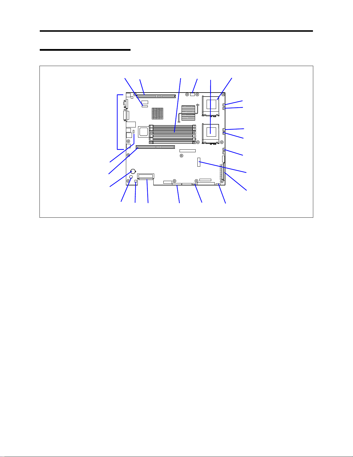
System Board
18
17
12 345 6
19
7-1
7-2
7
7
7
-3
-4
-5
8
16
101112131415
1 ICMB connector
2 PCI riser card connector
(Low-profile boards only. 66 MHz/64-bit)
3 DIMM sockets (for interleave memory)
(Starting from the top of the sockets that are shown above, the sockets are sequentially
numbered #3B, #2B, #1B, #3A, #2A, and #1A.)
4 USB connector(front panel)
5 Processor #1 (CPU#1) socket
6 Processor #2 (CPU#2) socket
7 Cooling fan connectors
7-1 System FAN 3
7-2 CPU 2 FAN
-3 System FAN 2
7
-4 CPU 1 FAN
7
7-5 System FAN 1
8 Peripheral interface connector
9 Main power connector
10 Power signal connector
11 SCSI IPMB connector
12 Configuration jumper switch
13 Internal SCSI connector (for internal hard disk drives)
14 SCSI/disk array controller access lamp connector
(For optional SCSI/disk array controller.)
15 Speaker
16 Lithium battery
17 PCI riser card connector
(Full-height boards. 66 MHz/64-bit)
18 Jumper pin for selecting a serial port DCD/DSR pin-out (J6A2 jumper block)
19 Connectors for external device
9

System Overview 1-9
STATUS INDICATORS
This section describes the server status indicators.
POWER Lamp ( )
The POWER lamp is lit (green) while the server power is on. It is off when no power is being
supplied to the server.
NOTE:
This server does not support power saving mode.
STATUS Lamp ( )
The STATUS lamp is lit (green) while the server is operating normally. (There is a STATUS
lamp located on both the front and rear panels of the server.) If the STATUS lamp is off or turns
amber color and flashes, it indicates that the server is in an abnormal state.
The table below lists and describes the STATUS lamp indications and any actions to be taken.
NOTES:
!
If ESMPRO or the offline maintenance utility is installed, you can
determine the cause of a failure by referring to the error log.
!
The system can be restarted automatically. However, if the automatic
restart cannot be performed for any reason, then the system must be
shutdown manually by turning the power off and back on.

1-10 System Overview
STATUS lamp
indication
On (green) The server is operating normally. –
Flashing
(green)
Off
On (amber)
Flashing
(amber)
Description Action
The server is operating with the
•
memory or CPU in degraded
state.
A 1-bit memory error occurs
•
frequently.
Power is off. –
POST is in progress. Wait while POST is checking the
CPU error occurred.
CPU temperature alarm was
detected. (Thermal-Trip)
A timeout occurred when the time
set for the watchdog timer was
reached.
An uncorrectable memory error was
detected.
PCI system error occurred.
PCI parity error occurred.
CPU bus error occurred.
A memory dump request was
issued.
A temperature alarm was detected. Check if the internal fans are clean
A voltage alarm was detected.
All the power supply units failed.
A fan alarm was detected. Check if the fan units are firmly
A temperature warning was
detected.
Identify the device in degraded state
by using the BIOS setup utility
"SETUP," and replace it as soon as
possible.
system. The STATUS lamp turns
green when POST is completed.
Turn the power off and on. If the
POST screen displays an error
message, record the message, and
contact your service representative.
Wait until the memory dump is
completed.
and if the fan units are firmly
connected.
If the STATUS lamp indication does
not change when the fans are
operating correctly, contact your
service representative.
Contact your service representative.
connected.
If the STATUS lamp indication does
not change when the fans are
operating correctly, contact your
service representative.
Check if the internal fans are clean
and if the fan units are firmly
connected.
If the STATUS lamp indication does
not change when the fans are
operating correctly, contact your
service representative.

System Overview 1-11
DISK ACCESS Lamp ( )
The DISK ACCESS lamp indicates the status of the hard disk mounted in the 3.5-inch device
bay.
The lamp turns green each time access is made to the hard disk.
When the DISK ACCESS lamp turns amber color, it indicates that a hard disk failure has
occurred. Check the hard disk lamp for the status of the failing hard disk.
When the DISK ACCESS lamp flashes between green and amber or if the lamp turns amber and
flashes, it indicates that rebuild (reconstruction) processing is being performed for a hard disk
connected to the internal disk array controller.
IMPORTANT:
If a hard disk in the server is connected to the internal disk
array controller, the access lamp signal cable (provided with the server)
must be connected from the disk array controller to the system board.
ACT Lamp ( )
The ACT lamp is a green color while the server is connected to the LAN. The lamp flashes while
the server is accessed via the LAN (during transmission/reception of packets). The number next
to the icon indicates the network port number on the rear panel of the server.
Disk Access Lamp
The disk access lamp on the floppy disk drive or CD-ROM drive is lit while the drive is accessed.

1-12 System Overview
Hard Disk Lamp
The disk lamp mounted in the 3.5-inch device bay indicates the following status:
Lamp
!
Flashing (green)
Lamp indicates that the hard disk is being accessed.
!
Lit (amber)
Lamp indicates a failure of a hard disk mounted in a disk array configuration.
NOTE:
Even if one of the hard disks fails in disk array configuration
(RAID1, RAID5, or RAID0+1), the server can continue operation.
However, the disk must be replaced as soon as possible, and
reconstruction (rebuild) processing must be performed. (The failing disk
can be replaced in hot swap mode.)
!
Flashing between green and amber
The lamp indicates that reconstruction (rebuild) processing is being performed for the
hard disk. (This flashing does not indicate a failure.) When a failing hard disk is
replaced in disk array configuration, the system automatically rebuilds the data. (Autorebuild function) The lamp switches back and forth between green and amber during
rebuild processing.
The lamp goes off when the rebuild processing has terminated. It turns amber color
when the rebuild processing fails.

System Overview 1-13
IMPORTANT:
If the server is turned off during rebuild processing, the
processing is stopped. Restart the server, mount the new hard disk in hot
swap mode, and then perform rebuild processing again. When using the
auto-rebuild function observe the following:
!
Do not turn the power off. (Once the power is turned off, the autobuild function does not start.)
!
Let 90 seconds or more pass between when dismounting a failing hard
disk and when mounting the new one.
!
Do not replace a failing hard disk while rebuild processing is being
performed for another hard disk.
LAN Connector Lamps
There are two lamps for each of the two LAN ports (connectors) on the rear panel.
Speed lampsLINK/ACT lamps
!
LINK/ACT lamps
Each LINK/ACT lamp indicates the status of its network port. While power is supplied
to the server and HUB and the connection is correct (LINK), the lamp is lit (green). The
lamp turns green and flashes while the network port is transmitting/receiving data (ACT).
If the lamp does not light in the LINK state, check if the network cable is connected
correctly. If the lamp still does not light when everything looks normal, the network
(LAN) controller may be faulty. In this case, contact your service representative.
!
Speed lamps
Each Speed lamp indicates that the communication mode of the standard network port of
the server is activated with the network interface of 100BASE-TX or 10BASE-T. When
the lamp is lit (amber), it indicates that the communication mode is activated with
100BASE-TX. When it is off, it indicates that the communication mode is activated with
10BASE-T.

1-14 System Overview
STANDARD FEATURES
High performance Expandability
! Intel Pentium III Processor
(1GHz/1.26GHz-S)
! High-speed 100BASE-TX/10BASE-T
interface (100Mbps/10Mbps supported)
! High-speed disk access
(Ultra160 SCSI x 2)
! High-speed memory access (133MHz,
ECC, registered, PC/133 compliant, 72bit, 68-pin, 3.3V)
High-reliability Many Available Features
! Memory monitoring feature (1-bit error
correction/ 2-bit error detection)
! CPU/memory degradation feature (logical
isolation of a failed device)
! Bus parity error detection
! Temperature detection
! Error notification
! Internal fan monitoring feature
! Internal voltage monitoring feature
! Auto-rebuild feature (optional, hot-
swappable)
! BIOS password feature
! Mechanical security lock
! Two PCI add-in card slots (full-length,
full-height 64-bit/66-MHz and low-profile
64-bit/66-MHz)
! Up to 6 GB of memory
! Three hot-swap SCSI hard disk drive
bays
! Up to two multi-processors are available
for upgrade.
! USB interface (USB-support driver is
required.)
! Two network ports
! Graphic accelerator "RAGE XL" support
! El Torito Bootable CD-ROM (no
emulation mode) format support
! POWER switch mask
! Software power-off
! Remote power-on feature
! AC-LINK feature
! Baseboard Management Controller
(BMC)
! Consoleless feature
Self-diagnosis
! Power On Self-Test (POST)
! Test and Diagnosis (T&D)
Management Utilities Easy and Fine Setup
! ESMPRO
! Management Workstation Application
(MWA)
Maintenance Features
! Off-line Maintenance Utility
! Memory dump feature using the DUMP
switch
! EXPRESSBUILDER (system setup
utility)
! Configuration Parameter Diskette Creator
! SETUP (BIOS setup utility)
! SCSISelect (SCSI device utility)

System Overview 1-15
Power Supply
The power supply is rated for 250 watts of power.
The power subsystem supports the remote management features, including remote enable that
permits power to be activated from a variety of sources.
Peripheral Bays
Your server supports a variety of standard PC AT-compatible peripheral devices. The chassis
includes the following peripheral bays:
!
A 3.5-inch front panel bay for mounting the standard 3.5-inch diskette drive (supports
720 KB and 1.44 MB diskette media)
!
A standard CD-ROM drive bay
!
Three hot-swap SCSI hard disk drive bays for mounting hard disk drives installed in
easily removable drive carriers.
NOTE: The hot-swap SCSI hard disk drive bays contain a hot-swap back
plane that require an 80-pin single connector attachment (SCA) connector
on the drives that you install.
System Cooling
The chassis includes a non-hot-swappable fan module with five fans for cooling the processor(s),
hard drives, and PCI cards. The fan system is located in the middle of the chassis to pull cooling
air through the chassis. The power supply contains two built-in fans for cooling.

1-16 System Overview
SAF-TE LOGIC
NOTE: SAF-TE Logic is in systems that include the hot-swap SCSI disk
drive cage. SAF-TE Logic is not available in systems that include the
standard SCSI disk drive cage.
The SCSI backplane includes SAF-TE (SCSI Accessed Fault Tolerant Enclosure) logic that
provides an interface to the disk subsystem that supports status signals, hot swapping drives, and
enclosure monitoring.
The transport mechanism for the standardized alert detection and status reporting is the SCSI bus.
Disk drives, power supplies, cooling fans, and temperature are continually monitored and the
conditions then reported over the SCSI bus to the system. When used with RAID management
software the user can be alerted of impending or imminent disk conditions requiring attention.
This allows the user to react to conditions that could normally go unnoticed until data loss.
SYSTEM BOARD FEATURES
The following subsections describe the major components of the system board. See "System
Board" earlier in this chapter.
Processor
The system board accommodates one or two Intel Pentium III processors with 512k cache in the
FC-PGA2 package. This processor uses the .13 micron technology and offers advanced
performance. The processor external interface operates at a maximum of 133 MHz.
Memory
The system board contains six 168-pin DIMM sockets each supporting 72-bit ECC (64-bit main
memory plus ECC) registered SDRAM DIMMs (PC-133 compatible). Memory is two-way
interleaved and partitioned in three banks. You may install a minimum of 256 MB (128MB × 2)
and as much as 6 GB.
The controller automatically detects, sizes, and initializes the memory array, depending on the
type, size, and speed of the installed DIMMs and reports memory size and allocation to the server
via configuration registers.
NOTE:
board.
Contact your service representative or dealer for a current list of approved
memory modules.
Use DIMMs that have been tested for compatibility with the server
 Loading...