

Page 1
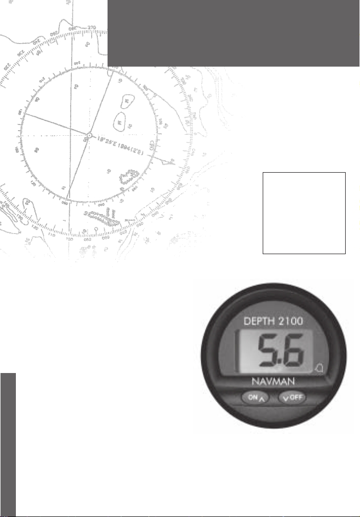
DEPTH 2100
Installation and
Operation Manual
English .............3
Français .........11
Deutsch ..........18
Nederlands .... 25
Svenska ......... 32
Español ..........39
www.navman.com
NAVMAN
Page 2

FCC Statement
Note: This equipment has been tested and found to comply with the limits for a Class
B digital device, pursuant to Part 15 of the FCC Rules. These limits are designed to
provide reasonable protection against harmful interference in a normal installation.
This equipment generates, uses and can radiate radio frequency energy and, if not
installed and used in accordance with the instructions, may cause harmful interference
to radio communications. However, there is no guarantee that interference will not
occur in a particular installation. If this equipment does cause harmful interference to
radio or television reception, which can be determined by turning the equipment off
and on, the user is encouraged to try to correct the interference by one or more of the
following measures:
Reorient or relocate the receiving antenna.
Increase the separation between the equipment and receiver.
Connect the equipment into an output on a circuit different from that to which the
receiver is connected.
Consult the dealer or an experienced technician for help.
A shielded cable must be used when connecting a peripheral to the serial ports.
2
NAVMAN
DEPTH 2100 Installation and Operation Manual
Page 3

Contents
1 Operation ......................................................................................................... 4
Alarms.............................................................................................................................. 4
Alarms On/Off.................................................................................................................. 4
Shallow Alarm .................................................................................................................. 4
Deep Alarm ...................................................................................................................... 4
2 Instrument Setup ............................................................................................. 5
Keel/Surface Offset......................................................................................................... 5
Transducer Setting.......................................................................................................... 5
Units of Measure ............................................................................................................. 5
3 Dual Station Operation................................................................................... 6
Master/Slave Selection .................................................................................................... 6
Linked or Separate Selection ........................................................................................... 7
4 Maintenance ................................................................................................... 7
5 Installation ...................................................................................................... 8
Instrument Installation ..................................................................................................... 8
6 Wiring .............................................................................................................. 8
Appendix A - Specifications ............................................................................. 9
Appendix B - Troubleshooting........................................................................ 10
Appendix C - How to contact us ..................................................................... 47
Important
It is the owner’s sole responsibility to install and use the instrument and transducer/s in a manner that will
not cause accidents, personal injury or property damage. The user of this product is solely responsible
for observing safe boating practices.
NAVMAN NZ LIMITED DISCLAIMS ALL LIABILITY FOR A NY USE OF THIS PRODUCT IN A WA Y THA T
MAY CAUSE ACCIDENTS, DAMAGE OR THAT MA Y VIOLATE THE LAW .
This manual represents the DEPTH 2100 as at the time of printing. Navman NZ Limited reserves the
right to make changes to specifications without notice.
Governing Language: This statement, any instruction manuals, user guides and other information relating
to the product (Documentation) may be translated to, or has been translated from, another language
(Translation). In the event of any conflict between any Translation of the Documentation, the English
language version of the Documentation will be the official version of the Documentation.
Copyright © 2002 Navman NZ Limited, New Zealand. All rights reserved. NAVMAN is a registered
trademark of Navman NZ Limited.
DEPTH 2100 Installation and Operation Manual
NAVMAN
3
Page 4
OFF
V
OFF
V
1 Operation
Whenever power is applied the depth sounder is
active and water depth is displayed. If the sonar signal
does not show a bottom the display will indicate “- -”.
This can occur if the water is aerated or the maximum
depth is exceeded. Note: The maximum depth
decreases as boat speed increases.
Alarms
Two types of alarms can be set; the Deep Alarm and
the Shallow Alarm. The Deep Alarm can be set as
high as 184 metres (605 feet) while the Shallow
Alarm can be set as low as 0.3 metre (1 foot).
Whenever the water depth is greater than the Deep
Alarm setting and the alarm is enabled an alarm will
sound. The alarm repeats two short beeps and
alternates DAL and the water depth on the display .
Whenever the water depth is less than the Shallow
Alarm setting and the alarm is enabled an alarm will
sound. The alarm repeats a single long beep and
alternates SAL and the water depth on the display .
Alarms On/Off
Alarm settings are saved in memory.
T o turn the alarm on, press (ON). An arrow on the
lower right corner of the display will show (next to the
Alarm Bell), to indicate that the alarms are on.
ON
^
ON
#
#
^
OFF
V
Press for 3
Seconds
851
120
T o turn the alarms off, press (OFF). The arrow in
the lower right corner will extinguish.
120
Note: The arrow will flash if alarms are turned ON
but the shallow alarm is individually set to OFF.
See next section.
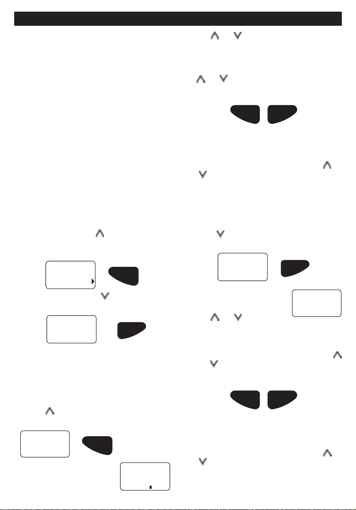
Shallow Alarm
To set the shallow alarm:
1. Press
SAL
2. After a few seconds the
4
for three seconds. The display will
show:
display will indicate the current
Shallow Alarm depth setting.
3. Use
4. When the alarm is set, exit by pressing both
Note: If the reading is decreased to below
1.5 feet (or equivalent) the display will
show OFF and the alarm will be disabled. The
alarm can also be disabled by pressing both
and for 5 seconds. The word OFF will be
displayed but the alarm depth will be retained for
future use.
and to change the value. If either
key is held depressed for more than one
second the reading will increase or decrease
rapidly.
and simultaneously. Alternatively, if no
keys are pressed for a period of 5 seconds the
normal depth display will resume.
V
OFFON
^
Press simultaneously to exit
Deep Alarm
To set the deep alarm:
1. Press for three seconds. The display will
show:
dAL
2. After two seconds the display
will indicate the current Deep
Alarm depth setting.
3. Use
4. When the alarm is set, exit by pressing both
Note: If the reading is increased one step above
600 feet (or equivalent) the display will
show OFF and the alarm will be disabled. The
alarm can also be disabled by pressing both
and for 5 seconds. The word OFF will be
displayed but the alarm depth will be retained for
future use.
and to change the
value. If either key is held depressed for more
than one second the reading will increase or
decrease rapidly.
and simultaneously. Alternatively, if no keys
are pressed for a period of 5 seconds the
normal depth display will resume.
^
Press simultaneously to exit
NAVMAN
DEPTH 2100 Installation and Operation Manual
V
OFFON
Press for
3 Seconds
OFF
V
850
Page 5

OFF
V
2 Instrument Setup
Keel/Surface Offset
An offset may be automatically added to or subtracted
from the depth reading to compensate for the location
of the transducer. This allows the instrument to
indicate the water depth relative to the bottom of the
keel or the surface of the water.
To set the keel/surface offset:
1. Apply power while holding down .
ON
^
Hold down during power up
2. When the unit is on, release . The display will
indicate if the current offset is keel offset or
waterline offset:
Hull Offset (Depth below the keel)
Surface Offset (Depth below the surface)
3. After 5 seconds the display will indicate the
current offset.
8. T o exit this mode, press and hold both
simultaneously. Alternatively, if no keys are
pressed for a period of 5 seconds normal depth
display will resume.
^
Press simultaneously
The display will now indicate the current water
depth.
V
OFFON
and
Transducer Setting
A T ransducer Setting is provided to allow the Depth
2100 to be used with different transducer types. The
default setting (= 0.0) is used for most transducers.
Some transducers ‘ring’ after the sonar transmit pulse
(just like hitting a bell). This ringing can be interpreted
as an echo from a shallow bottom. The setting is
used to increase the required level that shallow
echoes must meet before they will be displayed.
If the Depth 2100 gives repeated false readings of
1.5 to 3 feet depth while in deep water the transducer
setting should be increased. Adjust it upward by 0.5
at a time and retest. The range of values is -0.9 to
+2.5. If the value is set too high it could cause erratic
readings in shallow water.
Changing the Transducer Setting:
1. Apply power while holding down
display will show either HOF or SOF for 7
seconds. Continue to hold the key down.
2. The display will show tdr.
. The
Note: A negative offset is used to display depth
below the keel and a positive offset is used to
display depth below the surface.
4. Use and to change the value. If either key
is held depressed for more than one second the
reading will increase or decrease rapidly.
5. The offset can be programmed in 0.1 unit steps
from -9.9 to 9.9 feet (or equivalent). When
programmed for a negative offset, ‘-’ will be
indicated on the left hand side of the display.
6. T o display depth below the keel enter the
vertical distance between the bottom of the keel
and the depth transducer as a negative value.
7. T o display depth below surface enter the
vertical distance from the waterline to the
depth transducer as a positive number (no
negative sign).
DEPTH 2100 Installation and Operation Manual
NAVMAN
tdr
3. Release the key.
4. After 2 seconds the display will show the
Transducer Setting value eg 0.0.
5. Use and to change the value.
6. T o exit this mode, press and hold both
simultaneously.
Units of Measure
To select the displayed unit
1. Apply power while holding down
OFF
V
.
Hold down
during power up
and
5
Page 6

2. When the unit is on, release . The display
will indicate the current display unit with:
8Ft
Feet Metres
888
8FA
Fathoms
3 Dual Station Operation
Multiple Depth 2100 instruments can be inst alled on
a single vessel. These instruments can be connected
together and configured to operate in a dual station
configuration. One instrument is designated as a
master and all other instruments, connected to it,
are configured as slaves. The master device is
connected to the depth transducer and determines
the water depth. This information is then displayed
on all slave devices connected to it. Slave devices
do not have transducers connected to them.
The slave devices can be configured to operate as
fully functional NMEA repeaters where they display
water depth, as displayed on the master device, and
share common alarm settings and keel offset values.
In this mode the common alarm settings can be
changed or activated/deactivated from either the
master or slave devices.
Alternatively, the slaves can be configured to operate
as independent slaves. In this mode the slaves display
the water depth received from the master, but have
independent alarm settings and keel offset values.
Note: The instrument designated as the
master device is the only instrument connected to
the depth transducer.
3. Use
4. T o exit this mode, press and hold both
and to change the value.
simultaneously. Alternatively, if no keys are
pressed for a period of 5 seconds normal depth
display will resume.
V
OFFON
^
Press simultaneously
The display will now indicate the current water
depth in the selected display unit.
and
Master/Slave Selection
To select the master/slave mode of operation:
1. Apply power while holding down
OFF
V
Hold down during power up
2. When the unit is on. The display will indicate
the current display unit:
.
8Ft
example
3. Continue to hold
the current master/slave selection.
4. Use
5. T o exit this mode, press and hold both
and to change the selection.
simultaneously. Alternatively, if no keys are
pressed for a period of 5 seconds normal
depth display will resume.
until the display indicates
Master Slave
V
OFFON
^
and
Press simultaneously
Note: If the data link is inadvertently brocken then
the display will alternate between -- and -SL.
6
NAVMAN
DEPTH 2100 Installation and Operation Manual
Page 7

Linked or Separate Selection
By default a dual station pair of Depth 2100
instruments automatically keep the following settings
the same in both instruments:
Alarms On/Off
Alarm Values (Deep and Shallow)
Keel Offset (see note)
Units of measure (see note)
Example: Switching an alarm off on the slave
instrument will also switch the alarm off on the master
instrument. The reverse also applies, alarms
changed on the master will be automatically changed
in the slave instrument.
Note: The keel offset and units of measure should
only be changed on the Master instrument.
If independent settings are required the link feature
can be disabled.
To enable or disable the linked mode:
1. Apply power while holding down
OFF
V
Hold down during power up
2. When the unit is on. The
display will first indicate the
current display unit:
.
8Ft
Example
3. Continue to hold . The
display will indicate the
current master/slave
selection.
4. Continue to hold
the current linked/separate selection.
Linked Separate
5. Use
6. T o exit this mode, press and hold both
Note: This setup procedure applies to the master
device and all slave devices. For separate
operation all devices, including the master, must
be set to Separate mode. Also, for linked operation
all devices, including the master, must be set to
Linked mode.
and to change the selection.
simultaneously. Alternatively, if no keys are
pressed for a period of 5 seconds normal
depth display will commence.
until the display indicates
^
V
Press simultaneously
Slave
and
OFFON
4 Maintenance
Y our depth sounder is designed for years of trouble free operation assuming proper installation and care are
provided. Following the operation and installation guidelines in this manual should ensure optimum
performance of the instrument. In the unlikely event that the instrument shall fail to perform or shall need
servicing, contact the dealer whom you purchased your Depth 2100 from.
DEPTH 2100 Installation and Operation Manual
NAVMAN
7
Page 8

5 Installation
Instrument Installation
The instrument can be easily installed in different
types of instrument panels.
1. Select a suitable location for the instrument.
When selecting the location for mounting, the
following are recommended:
• Controls of the instrument must be
accessible to the user.
• Electrical connections must be routed to
the boat system as directly as possible,
minimising the length of cable where
practical.
• Location should provide as much protection
from the elements as possible.
• The panel for mounting the instrument
should be 3 mm to 19 mm (1/8 to 3/4 inch)
thick.
• The space behind the instrument panel
must have a depth of at least 95 mm (3.75
inches).
2. Drill a 51 mm (2-inch hole) on the instrument
panel in the selected location.
3. With the mounting bracket removed, insert the
instrument into the hole until the back of the face
plate is flush with the outside mounting wall.
4. Slide the bracket over the body of the
instrument. Note: Orient the bracket in such a
manner that it does not cover the buzzer.
5. Tighten the mounting nut until the bracket is
secure.
6. Connect the power cord at the back of the
instrument to a 12 V power supply which is
active whenever the ignition switch is on.
The red lead should be connected to the
positive terminal of the power supply via
a 1 amp fuse or a 1 amp circuit breaker.
2.5"
63.5 mm
.75"
19.0 mm
3.75"
95 mm
The black lead should be connected to the
negative terminal.
7. Obtain the power from a 12 V source as
directly as possible. Avoid power circuits which
share loads with ignition, alternators, radio
transmitters, etc. Excessive electrical noise
associated with such devices may prevent the
instrument from operating properly.
8. Connect the RCA phono plug on the
transducer cable to the instrument. Extension
cables are available from your NAVMAN dealer
if the transducer cable is too short.
Instrument Panel
Mounting Nut
51 mm (2 inch) Hole
Instrument
Sealing Gasket
Mounting
Bracket
6 Wiring
• Red (+) Terminal
• Black (-) Terminal
• Orange External Buzzer
Use for optional external buzzer (use red (+)
terminal to complete circuit). If unused then
tape to avoid shorting.
• Brown Data input/output
Y our Depth 2100 can be used as a repeater for
another DPT or DBT NEMA depth sounder . If
unused then tape to avoid shorting.
IMPORT ANT : If unsure about wiring contact
your nearest NAVMAN dealer .
8
RCA Jack
Connector
NAVMAN
Buzzer
Bracket
DEPTH 2100 Installation and Operation Manual
600 mm (24 inch)
Power Cord
Red (+)
Black (-)
Orange
Brown
Page 9

Appendix A - Specifications
• Size
Mount: 51 mm (2") diameter hole
Depth behind face plate: 95 mm (3.75") max.
Display: 3-character LCD
• Colour
Black bezel.
• Backlighting
Red coloured diffused lighting for display.
• Water Integrity
Front will withstand direct water spray.
• Depth/Alarm Range
2.0-600 feet
0.6-184 metres
0.3-100 fathoms
(to 9.9 in tenths)
• Sensitivity
Better than 0.05 mV RMS at 200 feet.
• Transmit Power
36 W RMS nominal at 13.6 V DC.
• Transducer
200 kHz 1900 pF/600 W parallel.
• Display Updating
1 second.
Display is backlit for
Night operation
• Operating Voltage
9.5 V DC to 16.5 V DC.
• Operating Temperature
0°C to 50°C (32°F to 122°F).
• Current Drain
150 mA max, including internal buzzer .
• Data Input/Output
Single wire data output/Input.
Dual station mode outputs NMEA sentences.
Dual station accepts NMEA sentences. In the
linked mode a dual station pair also transfer
function settings eg. Alarm on/off.
• NMEA Output
DPT.
• NMEA Input
DPT and DBT.
• External Buzzer Output
12 V DC Buzzer, 100 mA max.
• RF Interference
<6 dB quieting on any marine radio channel
(with 3 dB gain antenna) within one meter of the
instrument. Complies with CE EMC standards
EN50081-1 and EN50082-1.
Alarm On/
Change Value up
DEPTH 2100 Installation and Operation Manual
NAVMAN
Change Value Down
Alarm Off/
9
Page 10

Appendix B - Troubleshooting
No display:
1. Check DC power connections and DC
polarity with voltmeter.
2. Check fuse.
No depth reading (--) at all depths:
1. Check transducer for growth or multiple coats
of paint.
2. Check the transducer cable for cuts and
sharp bends.
3. Check that the transducer connection behind
the Depth 2100 is firm and free of corrosion.
Erratic readings while moored:
1. Check transducer for growth or multiple coats
of paint.
Erratic readings while moving:
1. Cavitation (air) under the face of the
transducer. Review installation and reinstall if
necessary.
Erratic readings only while engine is
running:
1. Re-route power and transducer cables away
from engine, ignition wires and battery
cables.
2. Add feed-through filter capacitor on the
positive terminal of the ignition coil.
3. Add an alternator whine filter to alternator .
4. Replace spark plug wire with resistive type.
NAVMAN
DEPTH 2100 Installation and Operation Manual
Page 11

Appendix C - How to contact us www.navman.com
NORTH AMERICA
NAVMAN USA INC.
18 Pine St. Ext.
Nashua, NH 03060.
Ph: +1 603 577 9600
e-mail: sales@navmanusa.com
OCEANIA
New Zealand
Absolute Marine Ltd.
Unit B, 138 Harris Road,
East Tamaki, Auckland.
Ph: +64 9 273 9273
e-mail:
navman@absolutemarine.co.nz
Papua New Guinea
Lohberger Engineering
Lawes Road, Konedobu
PO Box 810
Port Moresby
Ph: +675 321 2122
Email: loheng@online.net.pg
Australia
NAVMAN AUSTRALIA PTY
Limited
Unit 6 / 5-13 Parsons St,
Rozelle, NSW 2039, Australia.
Ph: +61 2 9818 8382
e-mail: sales@navman.com.au
SOUTH AMERICA
Argentina
Costanera UNO S.A.
Av Presidente R Castillo y
Calle 13
1425 Buenos Aires, Argentina.
Ph: +54 11 4312 4545
e-mail:
purchase@costanerauno.com.ar
Website:
www.costanerauno.ar
Brazil
REALMARINE
Estrada do Joa 3862,
CEP2611-020,
Barra da Tijuca, Rio de Janeiro,
Brasil.
Ph: +55 21 2483 9700
e-mail:
vendas@marinedepot.com.br
Equinautic Com Imp Exp de
Equip Nauticos Ltda.
Av. Diario de Noticias 1997 CEP
90810-080, Bairro Cristal, Porto
Alegre - RS, Brasil.
Ph: +55 51 3242 9972
e-mail:
equinautic@equinautic.com.br
ASIA
China
Peaceful Marine Electronics Co. Ltd.
Hong Kong, Guangzhou,
Shanghai, Qindao, Dalian.
E210, Huang Hua Gang Ke Mao
Street, 81 Xian Lie Zhong Road,
510070 Guangzhou, China.
Ph: +86 20 3869 8784
e-mail: sales@peaceful-marine.com
Website: www.peaceful-marine.com
India
Access India Overseas Pvt
A-98, Sector 21, Noida, India
Ph: +91 120 244 2697
Email: vkapil@del3.vsnl.net.in
Indonesia
Polytech Nusantara
Graha Paramita 2nd Floor
Jln Denpasar Raya Blok D2
Kav 8 Kuningan, Jakarta 12940
Tel: 021 252 3249
Korea
Kumhomarine Technology Co., Ltd.
#604-842, 2F, 1118-15,
Janglim1-Dong, Saha-Gu
Busan, Korea
Ph: +82 51 293 8589
e-mail: info@kumhomarine.com
Website: www.kumhomarine.com
Maldives
Maizan Electronics Pte. Ltd.
8 Sosunmagu Male
Ph: +960 78 2444
Email: ahmed@maizan.com.mv
Singapore
RIQ PTE Ltd.
81, Defu Lane 10, Hah Building,
#02-00 Singapore 539217
Ph: +65 6741 3723
e-mail: riq@postone.com
Taiwan
Seafirst International Corporation
No.281, Hou-An Road
Chien-Chen Dist.
Kaohsiung, Taiwan R.O.C.
Ph: +886 7 831 2688
e-mail: seafirst@seed.net.tw
Thailand
Thong Electronics (Thailand)
Company Ltd.
923/588 Thaprong Road,
Mahachai,
Muang, Samutsakhon 74000,
Thailand.
Ph: +66 34 411 919
e-mail: thonge@cscoms.com
Vietnam
Haidang Co. Ltd.
16A/A1E, Ba thang hai St.
District 10, Hochiminh City.
Ph: +84 8 86321 59
e-mail: sales@haidangvn.com
Website: www.haidangvn.com
MIDDLE EAST
Lebanon and Syria
Letro, Balco Stores,
Moutran Street, Tripoli VIA Beirut.
Ph: +961 6 624512
e-mail: balco@cyberia.net.lb
United Arab Emirates
Kuwait, Oman, Iran & Saudi Arabia
Abdullah Moh’d Ibrahim
Trading, opp Creak Rd.
Baniyas Road, Dubai.
Ph: +971 4 229 1195
e-mail: mksq99@email.com
AFRICA
South Africa
Pertec (Pty) Ltd Coastal,
Division No.16 Paarden Eiland Rd.
Paarden Eiland, 7405
Postal Address: PO Box 527,
Paarden Eiland 7420
Cape Town, South Africa.
Ph: +27 21 511 5055
e-mail: info@kfa.co.za
EUROPE
France, Belgium and
Switzerland
PLASTIMO INTERNATIONAL
15, rue Ingénieur Verrière,
BP435,
56325 Lorient Cedex.
Ph: +33 2 97 87 36 36
e-mail: plastimo@plastimo.fr
Website: www.plastimo.fr
Germany
PLASTIMO DEUTSCHLAND
15, rue Ingénieur Verrière
BP435- 56325 Lorient Cedex.
Ph: +49 6105 92 10 09
+49 6105 92 10 10
+49 6105 92 10 12
e-mail:
plastimo.international@plastimo.fr
Website: www.plastimo.de
Italy
PLASTIMO ITALIA
Nuova Rade spa, Via del Pontasso 5
I-16015 CASELLA SCRIVIA (GE).
Ph: +39 1096 8011
e-mail: info@nuovarade.com
Website: www.plastimo.it
Holland
PLASTIMO HOLLAND BV.
Industrieweg 4-6,
2871 RP SCHOONHOVEN.
Ph: +31 182 320 522
e-mail: info@plastimo.nl
Website: www.plastimo.nl
United Kingdom
PLASTIMO Mfg. UK Ltd.
School Lane - Chandlers Ford
Industrial Estate,
EASTLEIGH - HANTS S053 ADG.
Ph: +44 23 8026 3311
e-mail: sales@plastimo.co.uk
Website: www.plastimo.co.uk
Sweden, Denmark or Finland
PLASTIMO NORDIC AB.
Box 28 - Lundenvägen 2,
47321 HENAN.
Ph: +46 304 360 60
e-mail: info@plastimo.se
Website: www.plastimo.se
Spain
PLASTIMO ESPAÑA, S.A.
Avenida Narcís Monturiol, 17
08339 VILASSAR DE DALT,
(Barcelona).
Ph: +34 93 750 75 04
e-mail: plastimo@plastimo.es
Website: www.plastimo.es
Portugal
PLASTIMO PORTUGAL
Avenida de India N°40
1300-299 Lisbon
Ph: +351 21 362 04 57
e-mail:
plastimo@siroco-nautica.pt
Other countries in Europe
PLASTIMO INTERNATIONAL
15, rue Ingénieur Verrière
BP435
56325 Lorient Cedex, France.
Ph: +33 2 97 87 36 59
e-mail:
plastimo.international@plastimo.fr
Website: www.plastimo.com
REST OF WORLD /
MANUFACTURERS
Navman NZ Limited
13-17 Kawana St. Northcote.
P.O. Box 68 155 Newton,
Auckland, New Zealand.
Ph: +64 9 481 0500
e-mail:
marine.sales@navman.com
Website: www.navman.com
DEPTH 2100 Installation and Operation Manual
NAVMAN
47
Page 12

Made in New Zealand
MN000205A
DEPTH 2100
Lon 174° 44.535’E
Lat 36° 48.404’S
NAVMAN
 Loading...