


R
INSTALLATION INSTRUCTIONS
HARDWIRE |
WIRELESS |
G E M - P 1 6 3 2
CONTROL PANEL/COMMUNICATOR
For use with "Classic" keypads (GEM-RP1CAe2, GEM-RP2ASe2, GEM-RP3DGTL and GEM-RP4RFC/GEM-RP4C) and with "K Series" keypads (GEM-K1CA, GEM-K2AS, GEM-K3DGTL, and GEM-K4RF/GEM-K4)
GEMINI |
|
SYSTEM READY |
|
|
|
|
01/01/03 |
12:00 AM |
||
|
STATUS |
|
|
NEXT/YES |
ARMED |
R 1 2 3 |
U |
||
|
P |
|||
|
B 4 5 6 |
PRIOR/NO |
||
|
|
Q |
||
|
|
|
|
AREA |
|
C 7 8 9 0 G |
|||
COMPUTERIZED SECURITY SYSTEM |
|
|
||
"K Series" GEM-K1CA
GEMINI
32 


 ENT A1
INTERIOR BYPASS FIRE/TBL SYS TBL CHIME
NEXT/YES
RA 1 2 3
B 4 5 6
AREA
C7 8 9 0 G
COMPUTERIZED SECURITY SYSTEM
R
"K Series" GEM-K3DGTL
GEMINI |
SYSTEM ARMED |
|
|
|
01/01/97 AC ON12:00AMREADY |
|
|
AC ON READY |
ARMED |
STATUS |
NEXT/YES |
|
||
|
A 1 2 3 |
|
|
R |
|
B 4 5 6
AREA
C7 8 9 0 G
COMPUTERIZED SECURITY SYSTEM
R
"K Series" GEM-K2AS
"K Series" GEM-K4RF
© Napco 2003 |
|
WI808F 8/03 |

THIS MANUAL INCLUDES FEATURES WHICH ARE ONLY AVAILABLE IN CONTROL PANEL FIRMWARE VERSION 10.0 OR LATER.
CHANGES FROM PREVIOUS EDITION
The following changes have been made to this manual (WI808F) since the previous edition (WI808E).
•Page 2, "Important Notice", deleted NOTE which begins, "Typically, most versions of the GEM-P1632 control panel can be upgraded…" and ends, "...affixed to the GEM-P1632 circuit board."
•Page 6 contained a note with an asterisk, " *Not Evaluated by UL", referencing the Residential Burglary and Commercial Burglary specifications. This note was changed to "Commercial Burglary Specifications have not been Evaluated by UL".
•Page 7, the M278 Line-Reversal Module and the Veri-Phone Two-Way Module accessories now reference an asterisk (*) in that they have not yet been evaluated by UL.
•Page 7, references to UL609, UL1610, and UL365 listings were removed. (the GEM-P816/1632 panels have not yet been evaluated to these standards). However, the listing of the Security Industry Association (SIA) False Alarm Reduction Standard CP-01 was added.
•Page 8 specified that the system be serviced once every three years; this time period specification was changed to "annually".
•All systems on Page 11 in WI808E have not been evaluated by UL and therefore were removed.
•Page 13 in the Siren/Bell Power section, the following statement was added: "In NFPA Household Fire Installations, only a single siren or bell can be used on this bell circuit."
•Page 33 listed the "Easy Exit Always Enabled in Interior Mode" definition. This definition was changed as follows: The entry name was changed to "Easy Exit"; the statement "Not Evaluated by UL" was added; the sentence, "Disable Dor Ubuttons to initiate Silent (Easy) Exit." was added.
•The glossary definition on Page 34, "Exit Urgency Annunciation" was modified as follows: The following sentence was removed, "When armed Stay, Silent Exit is evoked and time is doubled (120 seconds by default)".
•The glossary definition on Page 37, "No EOL Resistor" now includes the following notation: "Note: Do not program for UL installations".
•The glossary definition listed on Page 37, "Panic Zone…" was changed as follows: The entry name is now listed as "Panics"; the following sentence was added: "Tamper must be enabled on the keypad".
•The glossary definition on page 40, "Swinger Shutdown" was modified.
•See the chart on Page 52, The entry for "Cross Zoning", the following sentence was added: "The Cross Zone set time = one (1) minute".
•All references to "Auto Reset after Alarm Time-Out" changed to "Auto Reset after Burglary Output Timeout".
•All references to 0720-Bit 6--"Enable PGM2 Chirp on Keyfob Arming" name changed to "Chirp Output on Keyfob Arm/Disarm".
•All references to 0722-Bit 0--"Automatic Interior Bypass" name changed to "Automatic Interior Bypass/Easy Exit".
•All references to 0721-Bit 7--"Enable Bell Output on Keyfob Arming" name changed to "Select Alarm Output for Keyfob Chirp".
IMPORTANT NOTICE
!GEM-P1632 panel version 10 requires the use of the following version keypads:
•GEM-RP1CAe2 Version 8, GEM-K1CA Version 8C
•
•
GEM-RP2ASe2, Version 6, GEM-K2AS, Version 6D
GEM-RP3DGTL, Version 2, GEM-K3DGTL, Version 2E
Upon entering program mode, the keypad display will flash the control panel firmware version, followed by the keypad firmware version:
GEM-RP1CAe2: [1008], GEM-RP2ASe2: [1006], GEM-RP3DGTL: [1002] GEM-K1CA: [1008], GEM-K2AS: [1006], GEM-K3DGTL: [1002]
Refer to accompanying GEM-P1632 Programming Instructions (WI897 and WI1148) for programming information.
NAPCO Security Systems, Inc.
333 Bayview Avenue, Amityville, New York 11701 For Sales and Repairs, call toll free: (800) 645-9445
For direct line to Technical Service, call toll free: (800) 645-9440 Internet: http://www.napcosecurity.com

WI808F |
8/03 |
|
|
|
TABLE OF CONTENTS |
|
|
|
|
||
|
.....................................................INTRODUCTION |
4 |
|
|
General Description................................................. |
4 |
|
|
Features.................................................................. |
4 |
|
|
Specifications.......................................................... |
6 |
|
|
Ordering Information ............................................... |
7 |
|
|
Summary of UL Requirements ................................ |
8 |
|
|
INSTALLATION...................................................... |
9 |
|
|
Mounting ................................................................. |
9 |
|
|
Wiring...................................................................... |
10 |
|
|
Wireless Systems.................................................... |
10 |
|
|
Typical Residential Fire Installation ......................... |
10 |
|
|
Typical Partitioned Installation................................. |
10 |
|
|
UL Commercial-Burglary Installations...................... |
11 |
|
|
TESTING THE SYSTEM......................................... |
12 |
|
|
WIRING CONNECTIONS........................................ |
13 |
|
|
Battery .................................................................... |
13 |
|
|
Transformer ............................................................ |
13 |
|
|
Siren/Bell Output ..................................................... |
13 |
|
|
Auxiliary Power ....................................................... |
13 |
|
|
PGM Outputs .......................................................... |
13 |
|
|
Remote Bus ............................................................ |
14 |
|
|
Earth Ground........................................................... |
14 |
|
|
Basic Zone Configuration ........................................ |
15 |
|
|
EZ Zone Doubling Configuration ............................. |
15 |
|
|
4-Wire Smoke Detectors ......................................... |
16 |
|
|
Page 3 ! |
2-Wire Smoke Detectors ......................................... |
16 |
Telephone Lines ..................................................... |
17 |
KEYPAD CONFIGURATION MODE ...................... |
18 |
Keypad Installation.................................................. |
18 |
Configuring the Keypads......................................... |
18 |
BASIC OPERATION............................................... |
21 |
User Codes & Zone Descriptions ............................ |
21 |
Arming and Disarming the System.......................... |
22 |
Bypassing Zones .................................................... |
24 |
Alarm Indication ...................................................... |
24 |
Function Mode/Dealer Program Mode..................... |
24 |
KEYPAD MESSAGES............................................ |
26 |
GLOSSARY............................................................ |
27 |
STANDBY-BATTERY CALCULATION WORKSHEET |
|
............................................................................... |
43 |
WIRING LEGEND................................................... |
44 |
KEYPAD PROGRAMMING MODES ...................... |
45 |
GEM-P1632 WIRING DIAGRAM ............................ |
50 |
CP-01 QUICK REFERENCE CHART ..................... |
51 |
FACTORY DEFAULT DESCRIPTION .................... |
53 |
FCC STATEMENT.................................................. |
55 |
LIMITED WARRANTY............................................ |
56 |
LNAPCO Security Systems |
X GEM-P1632 Installation Instructions |

Features
!Page 4 |
WI808F 8/03 |
INTRODUCTION
GENERAL DESCRIPTION
Napco's Gemini GEM-P1632 is a state-of-the-art microcomputer-based burglary and residential fire alarm control panel of modular design. Integrally an 8-zone panel, it will support up to 32 zones with the use of zone doubling, optional zone expansion modules, wireless receiver modules and/or GEM-RP1CAe2/GEM-K1CA Keypads. Each panel includes an integral digital communicator.
The control panel features programmable area partitioning. That is, the system may be divided into up to two discrete multiple-zone areas, each allowing access by only those users programmed for their respective area.
Opening Suppression and Closing Suppression, available through Napco Quickloader software, suppress reporting within programmed “windows”. Conversely, Exception Reporting can transmit a “fail to close” if the panel is not armed within programmed intervals and, similarly, a “fail to open” if the panel is not disarmed within programmed intervals. Furthermore, the panel can be programmed to automatically arm either area at any time. A log containing up to 400 events (accessible through QuickloaderTM software) monitors control-panel activity referenced to a precision real-time clock. A detailed event history may be displayed at the computer, using Napco’s PCD-Windows Quickloader Software.
Keypads feature a liquid-crystal display for messages. In normal use, the LCD shows zone identification and status messages. Conventional LEDs and a sounder are also provided for annunciation.
Data may be quickly and easily downloaded to the control panel using a PC-compatible computer with Napco's PCDWindows Quickloader software and PCI2000 computer interface. Or, the panel may be programmed using the keypad in its secondary mode of operation. In the keypad programming modes (there are two: Dealer and User), the LCD shows memory address, data values, programming prompts, and the alphanumeric characters required for entering up to 32 user codes and custom zone descriptions.
NOTE: Failure to install and program as described in this manual for UL-listed systems voids the listing mark of Underwriters Laboratories, Inc.
FEATURES
Control Panel Features
!Eight end-of-line-resistor burglary zones programmable for Area (expandable to sixteen end-of-line resistors with zone doubling), Exit/Entry Delay, Interior (Stay) Bypass, Exit/Entry Follower, Day Zone, Chime, Fire options, Swinger Shutdown, Zone Anding and a variety of other features.
!Supports up to 32 zones with optional zone-expansion modules, wireless receiver modules and 4-zone keypads. !Supports up to 32 individually coded users.
!Supports three outputs (Bell, PGM1 and PGM2) and up to 8 external relay outputs (using Relay Module RB3008, RM3008 or the GEM-OUT8. See Relay Control in glossary for more information).
!Supports three keypad panics: Fire, Police & Auxiliary !Supports two independent area partitions.
!Supports up to seven separate access stations (keypads) by up to 32 users.
!Supports up to 8 separately-addressable X-10 devices with the GEM-X10 KIT and PC04 interfaces. !English-language prompts & system status messages.
!User-customized zone descriptions, re-programmable as required. !Supports 2-wire and 4-wire smoke detectors.
!Reports alarms, restores and troubles by zone. !400 Event Log.
!Two programmable entry delay times. !One Interior Zone Group
!Dynamic battery test interrupts charging and places battery under load every four hours. !Chime by zone; programmable duration.
!Quickloader programmable. !2 PGM outputs.
!Supports Gemini Wireless Devices
XGEM-P1632 Installation Instructions |
LNAPCO Security Systems |

WI808F 8/03 |
Page 5 ! |
Communicator Features
!Compatible with all major receiver formats, including 4/2, SIA and Point ID (except Radionics Modem II). !Rotary dial and TouchToneTM with Rotary backup.
!Three 20-digit telephone numbers.
!Backup Reporting; Double Reporting; Split Reporting. !32 User Codes with Opening/Closing -Reporting by user. !AC Failure Reporting with programmable report delay. !Supervised telephone line with a fixed 60 second delay. !Pager Capability.
!Keypad Features.
!English-language LCD display; LED and sounder annunciators. !Supports up to seven 4-wire keypads.
!Provisions for fire, police and auxiliary panic alarms.
!Integral 4-zone EZM included in each keypad (GEM-RP1CAe2/GEM-K1CA only). !Fault-Find diagnostics simplify troubleshooting.
SIA CP-01 Features.
!See page 51-52 for complete information regarding the Factory Program complies with the Security Industry Association False Alarm Reduction Control Panel-01 Standard (SIA FAR CP-01).
IMPORTANT NOTE
This manual supports the keypad programming of the GEM-P1632 control panel with the NAPCO "classic" GEMRP1CAe2, GEM-RP2ASe2, and GEM-RP3DGTL keypads as well as the GEM-K1CA, GEM-K2AS, and GEM-K3DGTL "K Series" keypads. The new "K Series" models offer the new STAY and AWAY buttons with simplified functionality, along with the new MENU and ENTER buttons.
While the instructions in this manual are depicted using the GEM-K1CA and GEM-K2AS keypads, the manual applies to both the "classic" and the "K Series" keypads.
Program Mode is the same for both keypads--only the button names have changed, as follows:
•The Abutton and the Rbutton operate identically (in Program Mode) for both keypads.
•The Dbutton and the Ubutton operate identically (in Program Mode) for both keypads.
•The  button and the
  button operate identically (in Program Mode) for both keypads. The words "NEXT/YES button" are used in this manual.
•The  button and the
  button operate identically (in Program Mode) for both keypads. The words "PRIOR/NO button" are used in this manual.
Features
LNAPCO Security Systems |
X GEM-P1632 Installation Instructions |

Specifications
!Page 6 |
WI808F 8/03 |
SPECIFICATIONS
GEM-P1632
Operating Temperature: 0-49°C (32-120°F)
Input Power: 16.5-18.0 VAC via CLASS 2 Plug-In 20VA, 40VA or 50VA Transformer
Loop Voltage: 10-13Vdc
Loop Current: 3mA without Zone Doubling, 2.4mA with Zone Doubling using a 2.2K Ohm end-of-line resistor (Model EOL2.2K); 5mA for 2-wire smoke-detector zones; 1.4 mA using a 3.9K Ohm resistor (Model EOL 3.9K) with Zone Doubling
Loop Resistance: 300 Ohm max.; 50 Ohm for 2-wire smoke-detector zones Alarm Voltage Output: 1
Programmable Negative Outputs: 2
Auxiliary Power Output: 11.7-12.5 VDC
Remote Power Output: 12 VDC regulated (for keypads)
Combined Standby Current (Remote Power + Aux. Power + Fire Power): See following charts.
RESIDENTIAL BURGLARY & COMMERCIAL BURGLARY*
16.5VAC |
BATTERY |
STANDBY |
ALARM |
STANDBY |
TRANSFORMER |
(12 VDC) |
CURRENT |
CURRENT |
TIME |
|
|
|
|
|
40VA/50VA |
7 AH |
650 mA |
2.0 A |
4 Hours |
|
|
|
|
|
20VA * |
7 AH |
500 mA |
2.0 A |
4 Hours |
|
|
|
|
|
20VA * |
7 AH |
500 mA |
2.0 A |
6 Hours |
|
|
|
|
|
|
|
|
|
|
|
|
RESIDENTIAL FIRE |
|
|
|
|
|
|
|
16.5VAC |
BATTERY |
STANDBY |
ALARM |
STANDBY |
TRANSFORMER |
(12 VDC) |
CURRENT |
CURRENT |
TIME |
|
|
|
|
|
40VA/50VA |
7 AH |
120 mA |
520 mA(1) |
24 Hours |
40VA/50VA * |
Two 7 AH |
360 mA |
280 mA(1) |
24 Hours |
20VA * |
7 AH |
120 mA |
360 mA(1) |
24 Hours |
20VA * |
Two 7 AH |
360 mA |
120 mA(1) |
24 Hours |
NOTE: (1) Alarm current can be increased by reducing standby current by the same amount. * Commercial Burglary specifications not evaluated by U.L.
RESIDENTIAL FIRE PROGRAMMING OPTION: Refer to GEM-P1632 Programming Instructions (WI897 and WI 1148) for programming information. This option changes the operation of the power supply in alarm conditions to optimize performance. In installations that do not monitor fire conditions (Residential and Commercial Burglary) U. L. allows the battery to be depleted in alarm conditions when AC is present. To prevent the regulator and rectifier from exceeding 75% of their rated temperature the regulator drops to 10V causing the battery to support the entire alarm current. In installations that do monitor fire conditions (Residential Fire) U.L. does not allow the battery to be depleted in alarm conditions when AC is present. Therefore, when this bit is set, the regulator is not dropped to 10V during alarm conditions. When this bit is set the current specifications for Residential Fire should not be exceeded. If the specifications are exceeded when a 40VA or 50VA transformer is used the regulator may exceed 75% of its rated temperature up to 85% of its rated temperature at which point the regulator will protect itself by current limiting. This would cause the battery to deplete, but no damage would occur to the panel. If a 20VA transformer is used and the Residential Fire current specifications are exceeded then the Transformer VA rating may be exceeded thereby damaging the transformer.
EZM Module:
GEM-EZM816: Input, 50mA
Keypad Current:
GEM-RP1CAe2: 100mA; 35mA if back lighting is disabled (cut W1, W2 & W3) PGM Output: 5mA, 12V Special Application
Maximum Number of Keypads: 7
Maximum Wiring Length for each run (#22AWG): 1000' divided by total number of keypads and EZMs on run Keypad Dimensions: 4” x 5” x 1” (HWD); 11.1cm x 14.9cm x 2.7cm (HWD)
XGEM-P1632 Installation Instructions |
LNAPCO Security Systems |

WI808F 8/03
ORDERING INFORMATION
System Components
GEM-P1632: Residential UL-Listed Burg and Fire Control Panel.
GEM-RP1CAe2: 32-Character LCD Burg & Fire Keypad with 4 EOL Zones.
GEM-RP2ASe2: LCD Burg & Fire Keypad with remote panic.
GEM-RP3DGTL: Burg & Fire Keypad.
GEM-RP4RFC: Digital Icon Burg & Fire Keypad with Integral RF Receiver.
GEM-RP4C: Digital Icon Burg & Fire Keypad.
GEM-K1CA: 32-Character LCD Burg & Fire Keypad with 4 EOL Zones.
GEM-K2AS: LCD Burg & Fire Keypad with remote panic. GEM-K3DGTL: Burg & Fire Keypad.
GEM-K4RF: Digital Icon Burg & Fire Keypad with Integral RF Receiver.
GEM-K4: Digital Icon Burg & Fire Keypad.
Optional Accessories and Peripherals
GEM-EZM8: 8 Zone Expansion Zone Module GEM-EZM816: 4-16 Zone Expansion Zone Module GEM-EVA 1: Electronic Voice Annunciator GEM-RECV8: Wireless Receiver, 8 Zones GEM-RECV16: Wireless Receiver, 16 Zones GEM-RECV96: Wireless Receiver, 96 Zones GEM-TRANS2: Window/Door Transmitter, 2-Point GEM-RTRANS: Recessed Window/Door Transmitter GEM-KEYF: Key Fob Transmitter
GEM-SMK: Wireless Smoke Detector GEM-PIR: Wireless PIR
GEM-PIRPET: Wireless Pet Immune Transmitter * GEM-DT: Wireless Dual-Technology Sensor GEM-GB: Wireless Glass-Break Detector * GEM-X10KIT: X-10 Interface *
GEM-OUT8: 8 output active low output module RM3008: Relay Module (in enclosure)
M278: Line-Reversal Module*
PS3002: Power-Supply Module, 13.2Vdc, 1.9A *
EOL2.2K: End-of-Line Resistor Assy., 2.2k Ohm, for Fire Circuit
FT2200: End-of-Line Relay/Resistor Supervisory Module RB1000: Relay Board, single output *
RBATH1: Dual Battery Harness RPB-3: Universal Keypad Mounting Box
TRF11: Transformer, 16.5Vac/40VA, Class 2 TRF14: Transformer, 16.5Vac/50VA, Class 2
Page 7 !
WL1: Wire Assembly with Lug Connector, 20” VERI-PHONE: Two-Way Voice/Listen-In Module*
PCD3000: Downloading Software (for DOS) for IBM PCCompatible*
PCD-Windows: Downloading Software (for Windows) for IBM PC-Compatible*
PCI2000/3000: Software with Interface for IBM PCCompatible Computer *
PCI-MINI: Notebook Computer Interface * W834-1: Keypad Cable, plug-in (20”) OI163: Instruction Manual, GEM-P1632 OI193: User Guide, GEM-RP1CAe2 OI192: User Guide, GEM-RP2ASe2 OI249: User Guide, GEM-RP3DGTL OI278: User Guide, GEM-RP4C & RP4RFC WI1212: Installation Manual, GEM-RP4C
WI1128: Installation Manual, GEM-RP4RFC OI279: User Guide, GEM-K1CA
OI280: User Guide, GEM-K2AS OI281: User Guide, GEM-K3DGTL OI283: User Guide, GEM-K4 & K4RF WI1178: Installation Manual, GEM-K4
WI1179: Installation Manual, GEM-K4RF
WI897: GEM-P1632 Programming Instructions (using
GEM-RP1CAe2 / GEM-K1CA keypads).
WI1148: GEM-P1632 Programming Instructions (using
GEM-RP2ASe2 / GEM-K2AS or GEM-RP3DGTL /
GEM-K3DGTL keypads).
WI808: GEM-P1632 Installation Instructions
WIZARD IIe: Telephone Interface Module *
* Not investigated by UL.
UL Listings
Household Burglar Alarm System Units: UL1023 Household Fire Warning System Units: UL985
Security Industry Association (SIA) False Alarm Reduction Standard CP-01
** Pending
Information Ordering
LNAPCO Security Systems |
X GEM-P1632 Installation Instructions |

Summary of UL Requirements
!Page 8 |
WI808F 8/03 |
Smoke Detectors, 4-Wire:
1.ESL 445AT, 445C, 445CT, 445CR, 445CRT
2.Hochiki America SLG-12 with YBC-RL4-RA Base
3.System Sensor 2312/24T; 1412; 1412TH; 2412TH
Subtract total smoke-detector alarm current from available standby current.
Note: Any normally-open devices that do not require power from the control panel, such as pull stations and thermostats may be used if acceptable to the Authority having Jurisdiction.
UL Compatible Smoke Detectors (Providing UL Recognition or Listing)
Manufacturer |
|
4-Wire |
|
2-Wire |
Smoke Detector |
|
Smoke Detector |
Smoke Detector * |
Base |
||
|
|
|
|
|
|
Napco |
|
FW-4 |
|
FW-2 |
|
|
|
|
|
|
|
Sentrol |
449AT |
449CLT |
712U |
731U |
701U |
|
449C |
449CSLT |
722U |
|
702U |
|
449CRT |
449CTE |
732U |
|
702RE |
|
449CST |
741U |
711U |
|
702RU |
|
449CSRT |
742U |
721U |
|
|
|
449CSRH |
|
721UT |
|
|
|
449CSST |
|
|
|
|
|
|
|
|
|
|
System |
1112 |
2112T |
2100 |
1100 |
|
Sensor |
2112 |
2112TSRB |
2100T |
|
|
|
|
|
|
|
|
Note: * Voltage Rating: 8.5-13.3 VDC, Maximum Number of Detectors: 10
SUMMARY OF UL REQUIREMENTS
Residential
!Recognized Limited-Energy Cable for initiating, indicating and supplementary circuits. !Initiating loops supervised if longer than 3 feet
!FT2200 End-of-Line Relay for Fire (if using 4-wire smoke detectors) !Minimum alarm timeout of 5 minutes
!Maximum exit time: 60 seconds !Maximum entry time: 45 seconds
!Do not program “Swinger Shutdown”, “Force Arming”, “Selective Bypass” or “50 ms Loop Response” !“Abort Delay” may not exceed 45 seconds
!Program “Disable Callback Download”
!Automatic dialer may not dial a police station number that has not been dedicated for such service !System must be tested at least weekly under AC/battery and Battery-Only conditions
!Replace the rechargeable battery at least every 5 years
!If the battery is heavily discharged, replace it or have it tested by a qualified technician !For silent panic, connect only to UL-listed holdup devices
!All zones must be programmed for “Priority” !Do not program any zones for “Keyswitch Arming” !System must be serviced at least once every year
!Residential Fire and Combination Residential Fire & Burglary must program “Residential Fire” !Keypad Expansion (EZM) Zones are not to be used as fire zones
!Keypad Auxiliary is not to be selected
!The GEM-K Series Keypads must have the indicators printed on the face label (Fire, Police and Auxiliary) covered by a supplied label if not in use.
XGEM-P1632 Installation Instructions |
LNAPCO Security Systems |

WI808F 8/03 |
Page 9 ! |
INSTALLATION
CAUTION: This equipment generates and uses radio-frequency energy. If not installed using conventional installation practices for RF devices, it may cause interference to radio and television reception. It has been tested and found to comply with the limits for a Class A computing device pursuant to Subpart B of Part 15 of FCC Rules, which are designed to provide reasonable protection against such interference. However, there is no guarantee that interference will not occur in a particular installation. If it has been found to cause interference to radio or television reception, which can be determined by removing and reapplying AC and battery power to the equipment, the installer should try to correct the interference by one or more of the following measures: reorient the receiving antenna; connect the power transformer to a different outlet so that the control panel and receiver are on different branch circuits; relocate the control panel with respect to the receiver.
MOUNTING
Control Panel
Choose a mounting location accessible to (a) a continuously-powered AC source, (b) system ground, a steel or copper ground rod, ideally no further away than 10 feet, and (c) telephone lines (keep telephone wiring away from keypad wires). Remove appropriate knockouts for cables. Place the control panel at a convenient viewing height and mark the mounting holes. Attach the enclosure using screws suitable for the mounting surface.
Grounding
Connect the control-panel grounding screw to a long steel or copper ground rod driven deeply into the earth. Do not use a gas pipe, plastic pipe or ac ground connections. Use at least 16-gauge wire. Make the run as short and direct as possible, without any sharp bends in the wire.
Keypad
A keypad should be located near each exit/entry door. The keypad features a handy pull-up reference label. Before mounting the keypad onto the wall, push the Sliding Label Plate (with label and felt backing affixed and handle facing forward) down the guides at the rear of the keypad until it snaps into place. Once installed, the Sliding Label Plate cannot be removed without first removing the keypad from the wall. Note: (1) The keypad fire and panic keys should not be considered a substitute for a listed manual initiating device, such as a pull box. (2) Each GEM-RP1CAe2 includes provisions for four additional zones. See ADDING EXPANSION ZONES.
If installing onto a double-gang box, insert mounting screws through the two vertical elongated holes on the left side of the case and into the box. If the box is visible when viewed from the front, adjust the keypad vertically and tighten the screws. Then, using hardware suitable for the mounting surface, add one or two screws at the right side of the keypad case directly into the wall to ensure a secure installation. Note: Do not overtighten the screws! Uneven walls may cause the keypad case to distort.
Mounting
LNAPCO Security Systems |
X GEM-P1632 Installation Instructions |
Wiring
!Page 10 |
WI808F 8/03 |
Wiring
Wire keypad(s), zones, expansion zone modules and output devices as shown on the Wiring Diagram. Note that the Wiring Diagram contains important information not available elsewhere in this manual.
CAUTION: Do not run telephone wiring near speaker wires; do not run keypad wiring with loop wiring.
Adding Expansion Zones
GEM-P1632-Series control panels will handle up to 16 zones as is, however this number may be increased to as many as 32 programmable zones using optional expansion zone modules (EZMs).
Wireless Systems
With the addition of at least one GEM-RECV series receiver, the GEM-P1632 will support up to 32 wireless transmitters. The panel can accommodate one or two receivers within the premises, responding to the one with the stronger transmitter signal. If any transmitters are selected for the default program, a GEM-RECV receiver will automatically be programmed.
The keypad can display the status of any transmitter, indicating the condition of the zone (normal or open) and transmitter troubles (low battery, tamper or supervisory failure), and signal strength of the last transmission. A receiver failure will be indicated by “E06-NN” (“no response”, with NN representing the receiver number).
TYPICAL RESIDENTIAL FIRE INSTALLATION (Where permitted by local codes)
At least one smoke detector should be installed directly outside each sleeping area. If there is more than one floor, additional smoke detectors should be installed on each level, including the basement. The living-area and basement smoke detectors should be installed near the stairway of the next upper level. For increased protection, additional detectors should be installed in areas other than those required, such as the dining room, bedrooms, utility room, furnace room, and hallways. Heat detectors, rather than smoke detectors, are recommended in kitchens, attics, and garages due to conditions that may result in false alarms and improper operation. Large areas and areas with partitions, ceiling beams, doorways, and open joists will require
additional detectors.
Refer to NFPA Standard No. 74 (National Fire Protection Association, Batterymarch Park, Quincy, MA 02269) for additional information, including proper mounting of detectors.
TYPICAL PARTITIONED INSTALLATION
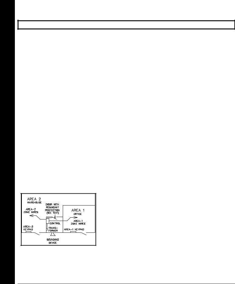
!Described and illustrated here are an example of a partitioned system with common-area protection of the control-panel room. This system meets UL requirements for a partitioned installation.
!Both areas must be owned and managed by the same person(s).
!Both areas must be part of one building at one street address.
!The control panel and all wiring protecting each partitioned area must be confined to the respective area and may not impinge upon the other area. This requires that the control panel room have redundant protection; that is (a) multiple sets of door contacts, each wired to a separate zone and (b) one of those zones programmed for each area. In order to gain access to this protected area without causing an alarm, both partitions must be disarmed. In lieu of redundant protection, 24-Hour Zones may be used. Any zone protecting the control panel
and transformer may not be programmed for bypass.
!The sounding device must be placed such that the bell test can be heard by all partitions. Note: NFPA 74 (Household Fire Warning Equipment) requires that a fire alarm audible device be installed indoors.
The User Program Code is not to be given to anyone except the authority responsible for all partitions.
XGEM-P1632 Installation Instructions |
LNAPCO Security Systems |
WI808F 8/03 |
Page 11 ! |
THIS PAGE INTENTIONALLY LEFT BLANK
LNAPCO Security Systems |
X GEM-P1632 Installation Instructions |

!Page 12 |
WI808F 8/03 |
TESTING THE SYSTEM |
|
After installation is completed, test the system as follows. |
|
!1. Call the central station to inform them of the test.
!2. Initiate an alarm, preferably on a zone that activates a steady siren, and verify proper signalling.
!3. Call the central station to confirm their receipt of a good transmission.
Note: Be sure to test all enabled keypad panics.
Signal Strength Testing/Wireless Systems
To test the operation of wireless transmitters, proceed as follows.
! 1. Enter the Fault-Find Mode. (See Dealer Mode on page 46. Panel must be disarmed).
! 2. Fault a point of the transmitter to be tested by opening the loop. If the signal strength of the transmitter is 3 or
greater, the keypad will beep, as follows: |
||
|
|
|
|
Signal Power |
Beeps |
|
0-2 |
0 |
|
3 |
1 |
|
4-5 |
2 |
|
6-7 |
3 |
|
8-10 |
4 |
SystemtheTesting |
! 3. Restore the wireless point (close the loop). |
|
! The transmitter signal strength will be displayed on a scale of 3-10 with 3 considered marginal and 10 |
||
|
||
|
considered excellent. Note that if the signal strength is less than 3, the keypad will not beep and the strength |
|
|
will be displayed. Except in the Fault-Find Mode, signal strengths less than 3 will be entered into the system |
|
|
log. Upon zone restore, the keypad will beep once. |
XGEM-P1632 Installation Instructions |
LNAPCO Security Systems |

WI808F 8/03 |
Page 13 ! |
WIRING CONNECTIONS
BATTERY |
7 |
The RED (+) and BLACK (-) flying leads must be connected to a 12VDC 4-7 AH Rechargeable Battery, to serve as backup power in the event of AC Power Failure. NOTE: To calculate the available standby time refer to the Standby-Battery Calculation Worksheet at the back of this manual.
TRANSFORMER
Connect a 16.5 VAC Transformer to Terminals 1 and 2, using a wire of #18 AWG. or larger at a distance of 15 ft. or less from the control panel. NOTE: Do not connect to a switched outlet.
SIREN/BELL POWER |
Connect the alarm sounding devices (self-contained sirens, |
|
speakers or a mechanical bell) to Terminals 3 and 4. Any self- |
|
contained siren requiring a 12 VDC input can be connected. |
|
When connecting a mechanical bell, it must be supervised |
|
using a 2.2k Ohm resistor. To connect 8 Ohm Speakers use a |
|
Siren Driver with the proper polarity observed. NOTE: Refer to |
|
the GEM-P1632 Wiring Diagram for alarm current specification. |
|
Note: In NFPA Household Fire Installations. only a single siren |
|
or bell can be used on this bell circuit. |
AUXILIARY POWER
Connect the auxiliary devices (motion detectors, glass breaks, etc.) to Terminals 5 and 6. Auxiliary Power provides 11.7-12.5 VDC nominal output which is used for powering auxiliary devices. NOTE: To calculate the available standby time refer to the Standby-Battery Calculation Worksheet at the back of this manual.
PGM OUTPUTS (PGM1 & PGM2) |
PGM1 and PGM2 are negative switched programmable outputs that can be activated depending on the programming options selected (see GEM-P1632 Programming Instructions). Connect the device controlled by the programmable output between terminal 5 (+) and the PGM output (-), either terminal 7 or 8. As an example, the connection to the RB1000 Relay Module is shown.
Outputs PGM & Power .Aux Power, Siren Transformer, Battery, Connections: Wiring
LNAPCO Security Systems |
X GEM-P1632 Installation Instructions |
Wiring Connections: Remote Bus & Earth Ground
!Page 14
REMOTE BUS
REMOTE BUS
ADDITIONAL
EZMs
Example:
(GEM-RP1CAe2) 2 LINE KEYPAD
STATUS
ARMED
WI808F 8/03
NOTE: Refer to the EZM Installation Instructions for specific wiring information.
AVAILABLE DEVICES |
AVAILABLE DEVICES |
GEM- |
|||
1. KEYPADS: GEM-RP2AS & GEM-1RP1CAe2. KEYPADS: GEM-RP1CAe2, GEM-RP2ASe2, GEM-RP3DGTL, |
|||||
2. X-10 INTERFACE: GEM-X10 |
K1CA, GEM-K2AS, GEM-K3DGTL (7 maximum) |
|
|||
3. WIRED ZONE EXPANDER: GEM-EZM816 |
|
|
|||
|
|
RECV8,2. |
GEM-RECV16 & GEMGEM-RECV96-X10 (8 devices maximum) |
|
|
4. WIRELESS RECEIVERS: GEM- |
|
||||
X-10 INTERFACE: |
|
||||
5. RELAY MODULE: RM3008 |
3. WIRED ZONE |
EXPANDER: GEM-EZM8, GEM-EZM816 (32 |
zones |
||
6. VOICE INTERFACE: GEM-EVA |
|||||
|
|
maximum) |
|
|
|
7. TELEPHONE INTERFACE: WIZARD2 |
|
|
|
||
4. WIRELESS RECEIVERS: GEM-RECV8, GEM-RECV16, GEM-RECV96 (32 zones maximum)
5. RELAY MODULE: RM3008 (8 relays maximum)
6. VOICE INTERFACE: GEM-EVA 1
7. TELEPHONE INTERFACE: WIZARD IIe
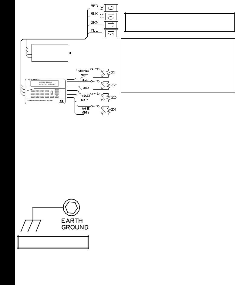
Connect the available devices as shown above to the remote bus terminals (9, 10, 11 & 12). Observe the correct color wire connections. When connecting the keypads, first configure them accordingly (refer to the Keypad Configuration Mode at the back of this manual). Keypads should be located near every exit/entry door. Up to seven keypads may be connected if the longest cable run from the panel, to the farthest keypad (daisy chained or home-run) is less than 1000 feet. The maximum distance for seven keypads is 300 feet using 22 AWG. wire. NOTE: When running keypad wire, avoid wiring parallel to other types of wiring.
EARTH GROUND
Connect the control panel EARTH GROUND screw to a metal cold-water pipe using at least a #16 AWG. wire. Do not use a gas pipe, plastic pipe or AC ground connections. Also, connect the circuit board to the metal enclosure. Connect a wire with a ground lug crimped or soldered onto one end of the EARTH GROUND screw to the cabinet. NOTE: Grounding connections should avoid bends in the grounding wire whenever possible.
NOTE: Do not use a gas pipe, plastic
XGEM-P1632 Installation Instructions |
LNAPCO Security Systems |

WI808F 8/03 |
Page 15 ! |
BASIC ZONE CONFIGURATION


 ( - )
( - )
The basic zone configuration for the GEM-P1632 is 8 zones. Connect as shown above to terminals 13-24. Normally Closed (N.C.) devices may be wired in series or Normally Open (N.O.) devices may be wired in parallel. Use the 2.2K Ohm end-of-line (E.O.L.) resistor in each zone, if selected in programming (refer to the GEM-P1632 Programming Instructions). Zones 1-8 can be selected for a “Fast Loop Response (50 ms)” or a “Normal Loop Response (750 ms)”. Other zone options include Zone Type (Entry/Exit, Interior, 24 Hour Protection, Trouble and Fire), Instant, Chime, Area Selection and PGM Output selection. Additional expansion zone modules or wireless sensor transmitters/receivers can be used to obtain zones numbered 9 through 32.
EZ ZONE DOUBLINGTM CONFIGURATION
The control panel zone configuration may be expanded from 8 to 16 zones without the use of EZM Modules. To do so simply select “EZ Zone Doubling” in programming (refer to the GEM-P1632 Programming Instructions) and connect zones as shown above. NOTE: If both zones in a zone-pair configuration (ex: zones 1 & 9 in the above diagrams) are to be used, then normally closed devices must be wired to both zones. The 3.9K EOL resistor must be placed at the end of the loop of the higher zone and the 2.2K EOL resistor must be placed at the end of the loop of the lower zone.
If Normally open zones for fire or panic devices are required, then the lower zone (2.2K EOL resistor) must be used and the higher zone (3.9K EOL resistor) must not be programmed for any area. Additional expansion zone modules or wireless sensor transmitters/receivers can be used to obtain zones numbered 9 through 32
WARNING: Assigning a fire zone or keyswitch zones to a zone doubled control will disable the respective complimentary zone. For example, if zone 8 is assigned as a fire zone, it will disable zone 16. If zone 3 is assigned as a fire zone, it will disable zone 11.
Configuration Doubling Zone EZ & Configuration Zone Basic Connections: Wiring
LNAPCO Security Systems |
X GEM-P1632 Installation Instructions |

Wiring Connections: 4-Wire Smoke Detectors & 2-Wire Smoke Detectors
!Page 16 |
WI808F 8/03 |
4-WIRE SMOKE DETECTORS |
|
4-WIRE SMOKE DETECTOR WIRING |
The GEM-P1632 can use conventional 12 VDC 4-wire |
|
smoke detectors. To use them, select fire zone |
|
programming option and do not select 2-wire smoke |
|
detector programming option for the desired fire zone |
|
(refer to the GEM-P1632 Programming Instructions). |
|
Set JP3 to the position as shown, if zones 7 or 8 are to |
|
be used. |
The GEM-P1632 can use conventional 12 VDC 4-wire smoke detectors. To use them, select fire zone programming option and do not select 2-wire smoke detector programming option for the desired fire zone (refer to the GEM-P1632 Programming Instructions). Set JP3 to the position as shown, if zones 7 or 8 are to be used.
Four wire smoke detectors may be connected to any programmed fire zone (1-8) as shown, within the panel. If the Zone Doubling is used (see EZ Zone Doubling Configuration), the respective complementary zones (9-16) are disabled when 4- wire smoke detectors are connected to zones 1-8. If external EZMs are used for zones 9-32, then 4-wire smoke detectors may be connected to any programmed fire zones (9-32).
Power must be obtained from terminal 25 and 6. If Fire Alarm Verification is desired to reset the smoke detectors, select this option for the desired fire zone.
2-WIRE SMOKE DETECTORS
2 -W IR E S M O K E
D E T E C T O R W IR IN G
Two-wire smoke detectors can only be connected to zones 7 and 8. To use them, select fire zone programming option and select 2-wire smoke detector programming option for the desired fire zone 7 or 8 (refer to the GEM-P1632 Programming Instructions) and set JP3 to the “2-WF” position as shown. Connect the 2-wire smoke detectors as shown.
If the Zone Doubling is used (see EZ Zone Doubling Configuration), the respective complementary zones (15 & 16) are disabled when 2-wire smoke detectors are connected to zones 7 & 8.
If Fire Alarm Verification is desired to reset the smoke detectors, select this option for the desired fire zone (zone 7 or 8).
XGEM-P1632 Installation Instructions |
LNAPCO Security Systems |
WI808F 8/03 |
Page 17 ! |
TELEPHONE LINES
RING  TIP
TIP RING TIP
Model 368 Cord
RING |
TIP |
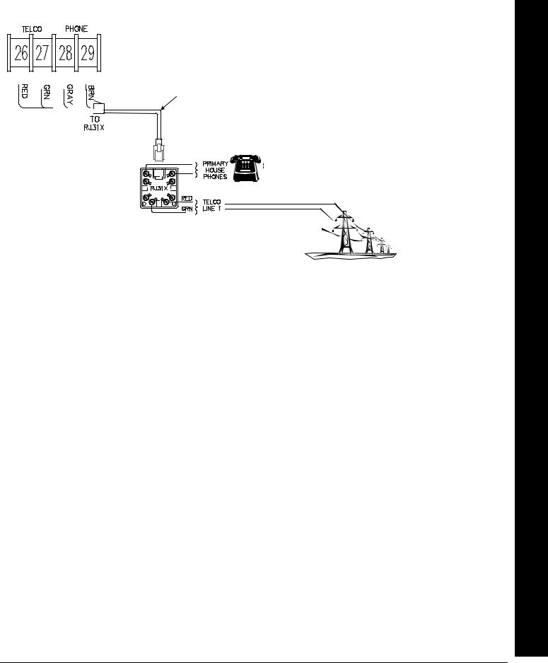
Connect the Model 368 Cord as follows: 26 (RED = Telco Ring), 27 (GREEN = Telco Tip), 28 (GRAY = Home Ring) and 29 (BROWN = Home Tip). Insert the modular plug into an approved USOCRJ31X jack (or a CA31A jack for Canadian installations). The Telco Line is used by the control panel to dial the central station and for downloading. This line should not be connected to party lines or coin operated telephones. If connected to a line with call waiting, then call waiting interrupt numbers must be programmed into the CS Telephone Numbers (refer to the GEM-P1632 Programming Instructions).
When communicating to central station and during downloading, the control panel seizes the telephone lines from the house phones, rendering them inoperative during communication. Upon completion of central station communication, the telephone line is restored to the house phones.
Lines Telephone Connections: Wiring
LNAPCO Security Systems |
X GEM-P1632 Installation Instructions |
 Loading...