


FW-C2Z, FW-C4Z and FW-C4EZ
Microprocessor Based - Fire Alarm Control Panels
INSTALLATION and OPERATION MANUAL
LNOTICE
All information, documentation, and specifications contained in this manual are subject to change without prior notice by the manufacturer.
©1999 by NAPCO Security Systems, Inc. Printed in CANADA, September 23, 1999
LT-636NAP Rev.1 (Operating Instruction is NP-779NAP Rev.1)
Page 1 of 36

TABLE of CONTENTS
1.0 |
INTRODUCTION . . . . . . . . . . . . . . . . . . . . . . . . . . . . . . . . . . . . . . . . . . . . . . . . . . . . . . . . . . . . . . . . . . . . . . . . . . . . . . . . . . . . . . |
Page |
4 of 36 |
|
|
1.1 OVERALL FEATURES: . . . . . . . . . . . . . . . . . . . . . . . . . . . . . . . . . . . . . . . . . . . . . . . . . . . . . . . . . . . . . . . . . . . . . . . . . . . . . |
Page |
4 of 36 |
|
2.0 |
GENERAL NOTES . . . . . . . . . . . . . . . . . . . . . . . . . . . . . . . . . . . . . . . . . . . . . . . . . . . . . . . . . . . . . . . . . . . . . . . . . . . . . . . . . . . . |
Page |
5 of 36 |
|
3.0 |
SYSTEM COMPONENTS . . . . . . . . . . . . . . . . . . . . . . . . . . . . . . . . . . . . . . . . . . . . . . . . . . . . . . . . . . . . . . . . . . . . . . . . . . . . . . |
Page |
6 of 36 |
|
|
3.1 |
MODELS . . . . . . . . . . . . . . . . . . . . . . . . . . . . . . . . . . . . . . . . . . . . . . . . . . . . . . . . . . . . . . . . . . . . . . . . . . . . . . . . . . . . . . . . |
Page |
7 of 36 |
|
3.2 |
ACCESSORIES . . . . . . . . . . . . . . . . . . . . . . . . . . . . . . . . . . . . . . . . . . . . . . . . . . . . . . . . . . . . . . . . . . . . . . . . . . . . . . . . . . |
Page |
7 of 36 |
4.0 |
MECHANICAL INSTALLATION and DIMENSIONS . . . . . . . . . . . . . . . . . . . . . . . . . . . . . . . . . . . . . . . . . . . . . . . . . . . . . . . . . . |
Page |
8 of 36 |
|
5.0 |
MODULE MOUNTING LOCATIONS . . . . . . . . . . . . . . . . . . . . . . . . . . . . . . . . . . . . . . . . . . . . . . . . . . . . . . . . . . . . . . . . . . . . . . |
Page 10 of 36 |
||
6.0 |
MODULE SETTINGS . . . . . . . . . . . . . . . . . . . . . . . . . . . . . . . . . . . . . . . . . . . . . . . . . . . . . . . . . . . . . . . . . . . . . . . . . . . . . . . . . . |
Page 12 of 36 |
||
|
6.1 MAIN FIRE ALARM MODULE . . . . . . . . . . . . . . . . . . . . . . . . . . . . . . . . . . . . . . . . . . . . . . . . . . . . . . . . . . . . . . . . . . . . . . . . |
Page 12 of 36 |
||
|
6.2 |
ZONE EXPANSION MODULE (Model FW-EZM4) . . . . . . . . . . . . . . . . . . . . . . . . . . . . . . . . . . . . . . . . . . . . . . . . . . . . . . . . |
Page 13 of 36 |
|
|
6.3 |
RELAY MODULES (Models FW-RB4 or FW-RB8) . . . . . . . . . . . . . . . . . . . . . . . . . . . . . . . . . . . . . . . . . . . . . . . . . . . . . . . |
Page 13 of 36 |
|
|
6.4 |
DACT / DIALER MODULE (Model FW-DACT) . . . . . . . . . . . . . . . . . . . . . . . . . . . . . . . . . . . . . . . . . . . . . . . . . . . . . . . . . . . |
Page 14 of 36 |
|
|
6.5 |
POLARITY REVERSAL and CITY TIE MODULE (MODEL: FW-RPM) . . . . . . . . . . . . . . . . . . . . . . . . . . . . . . . . . . . . . . . . |
Page 14 of 36 |
|
7.0 |
FIELD WIRING . . . . . . . . . . . . . . . . . . . . . . . . . . . . . . . . . . . . . . . . . . . . . . . . . . . . . . . . . . . . . . . . . . . . . . . . . . . . . . . . . . . . . . . |
Page 15 of 36 |
||
|
7.1 GENERAL FIELD WIRING CONSIDERATIONS . . . . . . . . . . . . . . . . . . . . . . . . . . . . . . . . . . . . . . . . . . . . . . . . . . . . . . . . . . |
Page 15 of 36 |
||
|
7.2 |
MAIN FIRE ALARM MODULE TERMINAL CONNECTIONS . . . . . . . . . . . . . . . . . . . . . . . . . . . . . . . . . . . . . . . . . . . . . . . . |
Page 16 of 36 |
|
|
7.3 |
ZONE EXPANSION MODULE (FW-EZM4) TERMINAL CONNECTIONS . . . . . . . . . . . . . . . . . . . . . . . . . . . . . . . . . . . . . . |
Page 18 of 36 |
|
|
7.4 |
RELAY MODULE ( FW-RB4 or FW-RB8) TERMINAL CONNECTIONS . . . . . . . . . . . . . . . . . . . . . . . . . . . . . . . . . . . . . . . |
Page 19 of 36 |
|
|
7.5 |
DACT / DIALER MODULE (FW-DACT) TERMINAL CONNECTIONS . . . . . . . . . . . . . . . . . . . . . . . . . . . . . . . . . . . . . . . . . |
Page 20 of 36 |
|
|
7.6 |
POLARITY REVERSAL and CITY TIE MODULE (MODEL: FW-RPM) TERMINAL CONNECTIONS . . . . . . . . . . . . . . . . |
Page 20 of 36 |
|
|
7.7 |
POWER SUPPLY CONNECTIONS . . . . . . . . . . . . . . . . . . . . . . . . . . . . . . . . . . . . . . . . . . . . . . . . . . . . . . . . . . . . . . . . . . . |
Page 21 of 36 |
|
|
7.8 |
WIRING TABLES . . . . . . . . . . . . . . . . . . . . . . . . . . . . . . . . . . . . . . . . . . . . . . . . . . . . . . . . . . . . . . . . . . . . . . . . . . . . . . . . . |
Page 22 of 36 |
|
|
|
WIRING TABLE FOR INITIATING CIRCUITS . . . . . . . . . . . . . . . . . . . . . . . . . . . . . . . . . . . . . . . . . . . . . . . . . . . . . . . . . . . |
Page 22 of 36 |
|
|
|
WIRING TABLE FOR NOTIFICATION CIRCUITS . . . . . . . . . . . . . . . . . . . . . . . . . . . . . . . . . . . . . . . . . . . . . . . . . . . . . . . . |
Page 22 of 36 |
|
8.0 |
SYSTEM CHECKOUT . . . . . . . . . . . . . . . . . . . . . . . . . . . . . . . . . . . . . . . . . . . . . . . . . . . . . . . . . . . . . . . . . . . . . . . . . . . . . . . . . |
Page 23 of 36 |
||
|
8.1 |
BEFORE TURNING THE POWER "ON" . . . . . . . . . . . . . . . . . . . . . . . . . . . . . . . . . . . . . . . . . . . . . . . . . . . . . . . . . . . . . . . |
Page 23 of 36 |
|
|
8.2 |
POWER-UP PROCEDURE . . . . . . . . . . . . . . . . . . . . . . . . . . . . . . . . . . . . . . . . . . . . . . . . . . . . . . . . . . . . . . . . . . . . . . . . . |
Page 23 of 36 |
|
|
8.3 |
TROUBLESHOOTING . . . . . . . . . . . . . . . . . . . . . . . . . . . . . . . . . . . . . . . . . . . . . . . . . . . . . . . . . . . . . . . . . . . . . . . . . . . . . |
Page 23 of 36 |
|
9.0 |
INDICATORS, CONTROLS, & OPERATION . . . . . . . . . . . . . . . . . . . . . . . . . . . . . . . . . . . . . . . . . . . . . . . . . . . . . . . . . . . . . . . . |
Page 24 of 36 |
||
|
9.1 |
INDICATORS . . . . . . . . . . . . . . . . . . . . . . . . . . . . . . . . . . . . . . . . . . . . . . . . . . . . . . . . . . . . . . . . . . . . . . . . . . . . . . . . . . . . |
Page 25 of 36 |
|
|
9.2 |
CONTROLS . . . . . . . . . . . . . . . . . . . . . . . . . . . . . . . . . . . . . . . . . . . . . . . . . . . . . . . . . . . . . . . . . . . . . . . . . . . . . . . . . . . . . |
Page 26 of 36 |
|
|
9.3 |
OPERATION . . . . . . . . . . . . . . . . . . . . . . . . . . . . . . . . . . . . . . . . . . . . . . . . . . . . . . . . . . . . . . . . . . . . . . . . . . . . . . . . . . . . . |
Page 26 of 36 |
|
|
9.4 |
CIRCUIT TYPES . . . . . . . . . . . . . . . . . . . . . . . . . . . . . . . . . . . . . . . . . . . . . . . . . . . . . . . . . . . . . . . . . . . . . . . . . . . . . . . . . . |
Page 27 of 36 |
|
10.0 SYSTEM CONFIGURATION . . . . . . . . . . . . . . . . . . . . . . . . . . . . . . . . . . . . . . . . . . . . . . . . . . . . . . . . . . . . . . . . . . . . . . . . . . . . |
Page 28 of 36 |
|||
11.0 WALK TEST OPERATION . . . . . . . . . . . . . . . . . . . . . . . . . . . . . . . . . . . . . . . . . . . . . . . . . . . . . . . . . . . . . . . . . . . . . . . . . . . . . . |
Page 30 of 36 |
|||
APPENDIX "A" - COMPATIBLE DEVICES . . . . . . . . . . . . . . . . . . . . . . . . . . . . . . . . . . . . . . . . . . . . . . . . . . . . . . . . . . . . . . . . . . . . |
Page 31 of 36 |
|||
APPENDIX "B" - FW-RB8 REMOTE ANNUNCIATOR . . . . . . . . . . . . . . . . . . . . . . . . . . . . . . . . . . . . . . . . . . . . . . . . . . . . . . . . . . . |
Page 33 of 36 |
|||
APPENDIX "C" - MODULE SPECIFICATIONS and FEATURES . . . . . . . . . . . . . . . . . . . . . . . . . . . . . . . . . . . . . . . . . . . . . . . . . . . |
Page 34 of 36 |
|||
APPENDIX "D" - POWER SUPPLY & BATTERY CALCULATIONS (SELECTION GUIDE) . . . . . . . . . . . . . . . . . . . . . . . . . . . . . . |
Page 35 of 36 |
|||
WARRANTY . . . . . . . . . . . . . . . . . . . . . . . . . . . . . . . . . . . . . . . . . . . . . . . . . . . . . . . . . . . . . . . . . . . . . . . . . . . . . . . . . . . . . . . . . . . . . |
Page 36 of 36 |
|||
Page 2 of 36

TABLE of FIGURES
Fig.1: |
FW-C2Z, FW-C4Z Enclosure Installation and Dimensions . . . . . . . . . . . . . . . . . . . . |
Page |
8 of 36 |
Fig.2: |
FW-C4EZ Enclosure Installation and Dimensions . . . . . . . . . . . . . . . . . . . . . . . . . . |
Page |
9 of 36 |
Fig.3: |
FW-C2Z, FW-C4Z Module Mounting Locations . . . . . . . . . . . . . . . . . . . . . . . . . . . . . |
Page 10 of 36 |
|
Fig.4: |
FW-C4EZ Module Mounting Locations . . . . . . . . . . . . . . . . . . . . . . . . . . . . . . . . . . . |
Page 11 of 36 |
|
Fig.5: |
Main Fire Alarm Module . . . . . . . . . . . . . . . . . . . . . . . . . . . . . . . . . . . . . . . . . . . . . . . |
Page 12 of 36 |
|
Fig.6: |
FW-EZM4 Zone Expansion Module . . . . . . . . . . . . . . . . . . . . . . . . . . . . . . . . . . . . . . |
Page 13 of 36 |
|
Fig.7: |
FW-RB4 or FW-RB8 Relay Module . . . . . . . . . . . . . . . . . . . . . . . . . . . . . . . . . . . . . . . |
Page 13 of 36 |
|
Fig.8: |
FW-DACT Dialer Module . . . . . . . . . . . . . . . . . . . . . . . . . . . . . . . . . . . . . . . . . . . . . . . |
Page 14 of 36 |
|
Fig.9: |
FW-RPM City Tie Module . . . . . . . . . . . . . . . . . . . . . . . . . . . . . . . . . . . . . . . . . . . . . . |
Page 14 of 36 |
|
Fig.10: |
General Field Wiring Considerations . . . . . . . . . . . . . . . . . . . . . . . . . . . . . . . . . . . . . |
Page 15 of 36 |
|
Fig.11: |
Main Fire Alarm Module Terminal Connections . . . . . . . . . . . . . . . . . . . . . . . . . . . . |
Page 16 of 36 |
|
Fig.11a: Main Fire Alarm Module Terminal Connections (continued) . . . . . . . . . . . . . . . . . . |
Page 17 of 36 |
||
Fig.12: |
FW-EZM4 Zone Expansion Module Terminal Connections . . . . . . . . . . . . . . . . . . . |
Page 18 of 36 |
|
Fig.13: |
FW-RB4 / FW-RB8 Relay Terminal Connections . . . . . . . . . . . . . . . . . . . . . . . . . . . . |
Page 19 of 36 |
|
Fig.14: |
FW-RPM Polarity Reversal and City Tie Module Terminal Connections . . . . . . . . . |
Page 20 of 36 |
|
Fig.15: |
Power Supply Connections . . . . . . . . . . . . . . . . . . . . . . . . . . . . . . . . . . . . . . . . . . . . |
Page 21 of 36 |
|
Fig.16: |
WIRING TABLE FOR INITIATING CIRCUITS . . . . . . . . . . . . . . . . . . . . . . . . . . . . . . . |
Page 22 of 36 |
|
Fig.17: |
WIRING TABLE FOR NOTIFICATION CIRCUITS . . . . . . . . . . . . . . . . . . . . . . . . . . . . |
Page 22 of 36 |
|
Fig.18: |
Indicators and Control Location . . . . . . . . . . . . . . . . . . . . . . . . . . . . . . . . . . . . . . . . |
Page 24 of 36 |
|
Page 3 of 36

1.0 INTRODUCTION
Introduction :
NAPCO's FW-C2Z, FW-C4Z and FW-C4EZ 24 Volt Fire Alarm Control Panels provide 1,2, 4, or 8 supervised Class B (UL Style B) Initiating Circuits, or 1,2, 4 supervised Class A (UL Style D) Initiating Circuits, and 2 or 4 supervised Class A or B (UL Style Z or Y) Notification Circuits. All Circuits are supervised for opens and ground faults, and Notification Circuits for shorts. Optional Modules include a FW-EZM4 Zone Expansion (required for full capacity in the FW-C4EZ only), a FW-DACT Dialer or a FW-RPM Polarity Reversal & City Tie Module, and FW-RB4 or FW-RB8 Relay Modules. The two enclosures are flush or surface mountable, and can be used for retrofits and on new installations.
1.1 Overall Features:
TThe small enclosure versions, FW-C2Z, & FW-C4Z have 1, 2, 4 Class B (Style B) Initiating Circuits respectively. The FW-C2Z & FW-C4Z may be configured as 1 or 2 Class A (Style D) Circuits respectively. These also have 2 Power Limited Class A/B (Style Z/Y) Notification Circuits with individual trouble indicators.
TThe large enclosure version, FW-C4EZ, has 4 Class B (Style B) Initiating Circuits which may be configured as 2 Class A (Style D) Circuits respectively. It also has 2 Power Limited Class A/B (Style Z/Y) Notification Circuits with individual trouble indicators. With a FW-EZM4 Zone Expansion, an extra 4 Class B (2 Class A) Initiating Circuits, and 2 Class A/B Notification Circuits are added.
TEach Initiating Circuit is configurable as a Normal or Verified Alarm. In addition, on a Class B FW-C4Z or FWC4EZ, Initiating Circuit 3 may be a Waterflow Zone (as may Initiating Circuit 7 if a FW-EZM4 is installed), and Initiating Circuit 4 may be a Latched or Non-Latched Supervisory Zone (as may Initiating Circuit 8 if a FWEZM4 is installed). On a Class A FW-C4EZ with a FW-EZM4, Initiating Circuit 3 may be a Waterflow Zone, and Initiating Circuit 4 may be a Latched or Non-Latched Supervisory Zone.
TNotification Circuits can be configured as Audible or Visual and as silenceable or non-silenceable. Audibles may be Steady, Temporal Code, California Code, or March Time.
TInitiating Circuits may be individually Disconnected by a Slide-Switch.
TConfigurable Signal Silence Inhibit (disabled or 1 minute), Auto Signal Silence (disabled or 5, 10, 20 minutes), and One-Man Walk Test.
TSubsequent Alarm, Supervisory, and Trouble operation
T4 wire resettable Smoke Power Supply (100 mA Max.).
TAuxiliary relay contacts for Common Alarm and Common Supervisory (disconnectable), and a Common Trouble relay.
TInterface for an RTI Remote Trouble Indicator.
TRS-485 Interface for 1 to 3 of FW-RB8 Remote Multiplex Annunciators on FW-C4Z & FW-C4EZ.
TThe FW-C2Z and FW-C4Z may use one of optional FW-DACT (Dialer), FW-RPM (City Tie), FW-RB4 or FWRB8 Relay Modules.
TThe FW-C4EZ may use one of optional FW-DACT (Dialer), FW-RPM (City Tie), and also one of FW-RB4 or FW-RB8 Relay Modules.
TSlide Switch Controls and LED Common Indicators.
TEasy Configuration via DIP Switches.
TExtensive transient protection
Page 4 of 36

2.0 GENERAL NOTES
Circuits and Zones:
“Circuits”
“Zone”
refers to an actual electrical interface, Initiating (Detection), Indicating (Signal), or Relay.
is a logical concept for a Fire Alarm Protected Area, and will consist of at least one Circuit.
Often the terms Zone and Circuit are used interchangeably, but in this Manual the term Circuit is used.
Wiring Styles:
Initiating Circuits are configured by default as Class B (Style B). They may be globally (all or none) configured as Class A (Style D) as described in the Configuration Section. This operation uses odd and even pairs of two-wire Class B (Style B) circuits to make one four-wire Class A (Style D) circuit, thus cutting in half the number of available Initiating Circuits.
Notification Circuits may be individually wired as Class A (Style Z) or Class B (Style Y) without affecting the number of circuits available (see Module wiring instructions).
Note: All Class B (Style B) initiating circuits are 2 wire smoke detector compatible. These circuits are current limited to 100 mA max. Refer to table on page 32 for a list of compatible smoke detectors.
Page 5 of 36
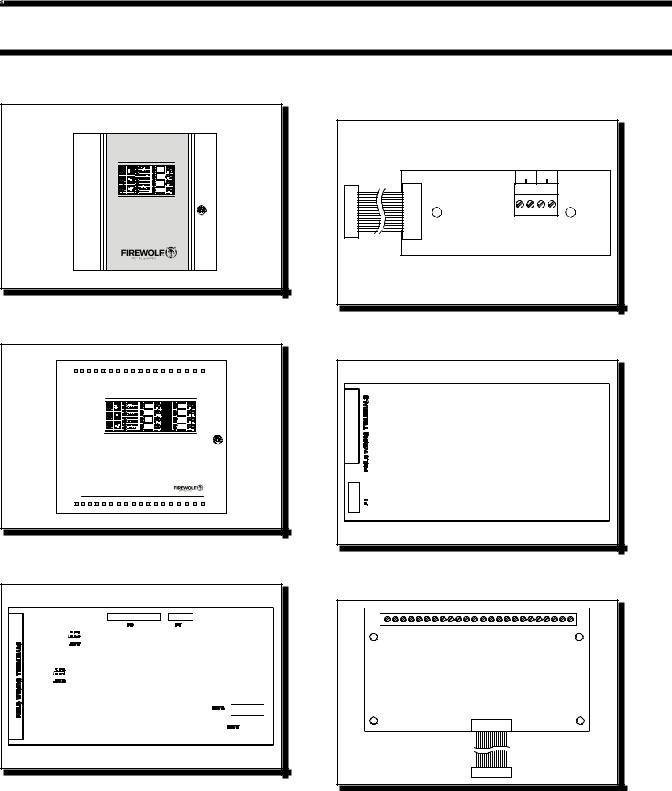
3.0 SYSTEM COMPONENTS
Model: FW-C2Z,C4Z Fire Alarm Control Panel |
Model: FW-RPM |
City Tie Module |
FW-C4Z
ZONE 1 |
ZONE 2 |
ZONE 3 |
ZONE 4 |
FIRE ALARM CONTROL PANEL
Model: FW-C4EZ Fire Alarm Control Panel
Model: FW-DACT Dialer Module
ZONE 1 |
ZONE 5 |
ZONE 2 |
ZONE 6 |
ZONE 3 |
ZONE 7 |
ZONE 4 |
ZONE 8 |
FIRE ALARM CONTROL
Model: FW-EZM4 Zone Expansion Module
Model: FW-RB4 & FW-RB8 4 & 8 Relay Module
Page 6 of 36
3.1 MODELS
Model: FW-C2Z Small enclosure Fire Alarm Control Panel with two Class B (Style B) or one Class A (Style D) Initiating Circuits, and 2 Power Limited Class A/B (Style Z/Y) Notification Circuits (1.70 amperes each, 2.4 amperes total) with individual trouble indicators. Common Alarm & Trouble Relays. Interface for Remote Trouble Indicator. Resettable Four Wire Smoke Detector Power Supply. May have one of FW-DACT, FW-RPM, FW-RB4, or FW-RB8 installed. Can be used with 4 amp-hour or 6.5 amp-hour batteries (2 required).
Model: FW-C4Z Small enclosure Fire Alarm Control Panel with four Class B (Style B) or two Class A (Style D) Initiating Circuits, and 2 Power Limited Class A/B (Style Z/Y) Notification Circuits (1.70 amperes each, 2.4 amperes total) with individual trouble indicators. Common Alarm & Trouble Relays. Interface for Remote Trouble Indicator and/or 1 to 3 of FW-RB8 Remote Multiplex Annunciators. Resettable Four Wire Smoke Detector Power Supply. May have one of FW-DACT, FW-RPM, FW-RB4, or FW-RB8 installed. Can be used with 4 amp-hour or 6.5 amp-hour batteries (2 required).
Model: FW-C4EZ Large enclosure Fire Alarm Control Panel with four Class B (Style B) or two Class A (Style D) Initiating Circuits, and 2 Power Limited Class A/B (Style Z/Y) Notification Circuits (1.70 amperes each, 5 amperes total) with individual trouble indicators. Common Alarm & Trouble Relays. Interface for Remote Trouble Indicator and/or 1 to 3 of FW-RB8 Remote Multiplex Annunciators. Resettable Four Wire Smoke Detector Power Supply. May have one of FW-DACT or FW-RPM, and one FW-EZM4 installed. May also have one of FW-RB4 or FW-RB8 installed. Can be used with 4 amp-hour, 6.5 amp-hour, or 10 amp-hour batteries (2 required).
Model: FW-EZM4 Zone Expansion Module for the FW-C4EZ. Brings the total capacity to eight Class B (Style B) or four Class A (Style D) Initiating Circuits, and 4 Power Limited Class A/B (Style Z/Y) Notification Circuits (up to 1.7 amperes each, 5 amperes total).
Model: FW-RB8 Relay Module for the FW-C4Z or FW-C4EZ. Adds eight configurable Form-C Relays rated 1A, 28 VDC.
Model: FW-RB4 Relay Module for the FW-C4Z or FW-C4EZ. Adds four configurable Form-C Relays rated 1A, 28 VDC.
Model: FW-DACT Digital Communicator / Dialer Module.
Model: FW-RPM City Tie / Reverse Polarity Module.
Model: CH-429 Accessory Mounting Plate for the FW-C2Z, or FW-C4Z if one of FW-RB4, FW-RB8, FW-RPM, or FW-DACT Modules are to be used.
3.2 ACCESSORIES
Model: FW-RA-LED 8 Zone Remote Annunciator (ULC and UL Approved)
Model: FW-RTI |
Remote Trouble Indicator (ULC and UL Approved) |
Page 7 of 36
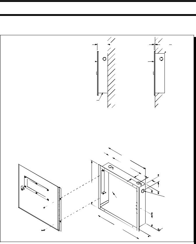
4.0 MECHANICAL INSTALLATION and DIMENSIONS
Install the enclosure as shown below for the FW-C2Z or FW-C4Z ...
Fig.1: FW-C2Z or FW-C4Z Enclosure Installation and Dimensions
MATERIAL: 18GA (0.048") THICK COLD ROLLED STEEL
FINISH: PAINTED
|
3 |
" |
5 |
" |
|||
3 |
- |
|
|
|
- |
||
|
|
||||||
|
8 |
|
16 |
||||
|
|
|
|
|
|
|
|
DOOR |
|
DOOR |
BACKBOX |
WALL |
|
BACKBOX
WALL
SURFACE |
FLUSH |
(SIDE VIEW) |
(SIDE VIEW) |
BACKBOX
5 |
" |
|
|
|
|
||
1- |
|
|
|
|
|||
8 |
|
|
|
|
|
||
DOOR |
|
|
|
|
13 |
3 |
" |
|
|
|
|
||||
|
|
|
|
- |
|||
|
|
|
|
|
4 |
|
|
|
|
|
|
|
|
1 |
|
|
|
|
|
10 |
- |
" |
|
|
|
|
|
|
|
2 |
|
|
5 |
" |
|
|
|
|
|
||
|
|
|
||
|
|
|
||
1" |
1- |
3 |
" |
|
8 |
|
1- |
||
|
|
|
4 |
|
14 |
-1" |
|
8 |
|
|
|
|
|
|
|
|
|
|
|
|
|
|
|
|
|
|
|
|
|
1 |
7 |
" |
||
|
|
|
|
|
|
|
|
|
|
|
|
|
|
|
|
|
|
|
|
|
|||||
|
|
|
|
|
|
|
|
|
|
|
|
|
|
|
|
|
|
|
|
|
1- " &- |
||||
|
|
|
|
|
|
7 |
|
|
|
|
|
|
|
|
|
|
8 |
8 |
|
||||||
|
|
|
|
|
|
" DIA. |
|
|
|
|
|
|
|
|
|
|
KNOCKOUT |
||||||||
|
|
|
|
|
|
|
|
- |
|
|
|
|
|
|
|
|
|
|
|
||||||
|
|
|
|
|
|
|
|
|
32 |
HOLE |
|
8" |
|
|
|
|
|
|
|||||||
|
|
|
|
|
|
|
|
|
|
|
|
|
|
|
|
|
|||||||||
|
|
|
|
|
|
|
|
|
|
|
|
|
|
|
|
|
|
|
|
|
|
|
|
|
|
|
|
|
|
|
|
|
|
|
|
|
|
|
|
|
|
|
|
|
12 |
3 |
" |
|
|
|
|
|
|
|
|
|
|
|
|
|
|
|
|
|
|
|
|
|
|
|
- |
|
|
|
|
||
|
|
|
|
|
|
|
|
|
|
|
|
|
|
|
|
|
|
|
|
4 |
|
|
|
|
|
|
|
|
|
|
|
|
|
|
|
|
|
|
|
|
|
|
|
|
|
|
|
|
|
|
|
|
|
|
|
|
|
|
|
|
|
|
|
|
|
|
|
|
|
|
|
|
|
|
|
|
|
|
|
|
|
|
|
|
|
|
|
|
|
|
3 |
7 |
" |
|
|
|
|
|
|
||||
|
|
|
|
|
|
|
|
|
|
|
|
|
- |
|
|
|
|
|
|
||||||
|
|
|
|
|
|
|
|
|
|
|
|
|
|
|
|
|
8 |
|
|
|
|
|
|
|
|
|
|
|
|
|
15 |
-1" |
|
|
|
|
|
|
|
|
|
|
|
|
|
|
|||||
|
|
|
|
|
|
|
|
|
|
|
|
|
|
|
|
|
|
|
|||||||
|
|
|
|
|
|
|
|
|
|
|
|
|
|
|
|
|
|
|
|||||||
#6 x 5/16" SCREW |
|
|
|
|
|
|
|
|
8 |
|
|
|
|
|
3 |
-1" |
|
|
|
|
|
|
|||
|
|
|
|
|
|
|
|
|
|
|
|
|
|
|
|
|
|
|
|
|
|
|
|||
|
|
|
|
|
|
|
|
|
|
|
|
|
|
|
|
|
|
|
|
|
|
|
|||
|
|
|
|
|
|
|
|
|
|
|
|
|
|
|
|
|
|
|
8 |
|
|
|
|
|
|
|
|
|
|
|
|
|
|
|
|
|
|
|
|
|
|
|
|
|
|
|
|
|
|
|
|
|
|
|
|
|
|
|
|
|
|
|
|
|
|
|
|
|
|
|
|
|
|
|
|
|
|
|
|
|
|
|
|
|
|
|
|
|
|
|
|
|
|
|
|
|
|
|
|
|
|
|
|
Page 8 of 36
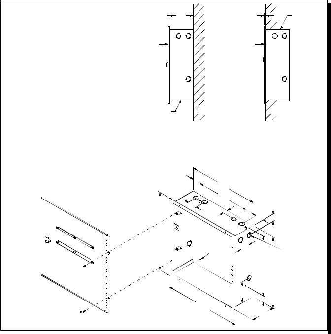
Fig.2: FW-C4EZ Enclosure Installation and Dimensions |
|
|
|
|
5 |
1 |
5 |
" |
BACKBOX |
- " |
- |
|||
|
4 |
16 |
|
|
DOOR |
|
DOOR |
|
|
MATERIAL: BACKBOX 18GA (0.048") THICK |
|
|
|
|
DOOR 16GA (0.059") THICK |
|
|
|
|
COLD ROLLED STEEL |
|
|
|
|
FINISH: PAINTED |
|
|
|
|
BACKBOX |
WALL |
|
|
WALL |
SURFACE |
|
|
FLUSH |
|
(SIDE VIEW) |
|
|
(SIDE VIEW) |
|
1-34"
|
|
|
|
|
|
|
|
|
|
|
|
|
|
|
|
|
|
|
|
|
|
|
|
|
|
14 |
-1" |
|
|
|
|
|
|
BACKBOX |
|
|
|
|
|
||||||
|
|
|
|
|
|
|
|
|
|
|
|
|
|
|
|
|
|
|
|
|
|
|
|
|
|
|
|
|
|
|
|
|
|
|
|
||||||||||
|
|
|
|
|
|
|
|
|
|
|
|
|
|
|
|
|
|
|
|
|
|
|
|
|
|
|
|
|
|
|
|
|
|
|
|
|
|
|
|
|
|
|
|
||
|
|
|
|
|
|
|
|
|
|
|
|
|
|
|
|
|
|
|
|
|
|
|
|
|
|
|
2 |
|
|
|
|
|
|
|
|
|
|
|
|
|
|
|
|
|
|
|
|
|
|
|
DOOR |
|
|
|
|
|
|
|
|
|
|
11" |
|
|
|
|
|
|
|
|
|
|
|
|
|
|
|
|
|
|
|||||||||||
|
|
|
|
|
|
|
|
|
|
|
|
|
|
|
|
|
|
|
|
|
|
|
|
|
|
|
|
|
|
|
|
|
|||||||||||||
|
|
|
|
|
|
|
|
|
|
|
|
|
|
|
|
|
|
|
|
|
|
|
|
|
|
|
|
|
|
|
|
|
|||||||||||||
|
|
|
|
|
|
|
|
|
|
|
|
|
|
|
|
|
|
|
|
|
|
|
|
|
|
|
|
|
|
|
|
|
|||||||||||||
|
|
|
|
|
|
|
|
|
|
|
|
|
|
|
|
|
|
|
|
2" |
|
|
|
1" |
|
|
|
|
|
|
|
|
3 |
" |
|
|
|
1 |
|
|
|
|
|||
|
|
|
|
|
|
|
|
|
|
|
|
|
|
|
|
|
|
|
|
|
|
|
|
|
|
|
|
|
|
|
|
|
|
|
|
|
|
|
|
|
|||||
|
|
|
|
|
|
|
|
|
|
|
|
|
|
|
|
|
|
|
|
|
|
|
|
|
|
|
|
|
|
|
|
|
|
|
|
|
|
|
|
|
|||||
|
|
|
|
|
|
|
|
|
|
|
|
|
|
|
|
|
|
|
|
|
|
|
|
|
|
|
|
|
|
|
|
|
|
|
- |
|
|
|
|
|
|
|
|||
|
|
|
|
|
|
|
|
|
|
|
|
|
|
|
|
|
|
|
|
|
|
|
|
|
|
|
|
|
|
|
|
|
|
|
1 |
|
|
|
1- |
" |
|
|
|
|
|
|
|
|
|
|
|
|
|
|
|
|
|
|
|
|
|
|
|
|
|
|
|
|
|
|
|
|
|
|
|
|
|
|
|
|
4 |
|
|
|
|
|
|
|
|
||
|
|
|
|
|
|
|
|
|
|
|
|
|
|
|
|
|
|
|
|
|
|
|
|
|
|
|
|
|
|
|
|
|
|
|
|
|
|
|
|
2 |
|
|
|
|
|
|
|
|
|
|
|
|
|
|
|
|
|
|
|
|
|
|
|
|
|
|
|
|
|
|
|
|
|
|
|
|
|
|
|
|
|
|
|
|
|
|
|
|
|
|
|
|
|
|
|
|
|
|
|
|
|
|
|
|
|
|
|
|
|
|
|
|
|
|
|
|
|
|
|
|
|
|
|
|
|
|
|
|
|
|
|
|
|
|
|
|
|
|
|
|
|
|
16 |
5 |
" |
|
|
|
|
|
|
|
|
|
|
|
|
|
|
|
|
|
|
|
|
|
|
|
|
|
|
|
|||||||||||
|
|
|
|
|
- |
|
|
|
|
|
|
|
|
|
|
|
|
|
|
|
|
|
|
|
|
|
|
|
|
|
|
|
|||||||||||||
|
|
|
|
|
|
|
|
|
|
|
|
|
|
|
|
16 |
|
|
|
|
|
|
|
|
|
|
|
|
|
|
|
|
|
|
|
|
|
|
1 |
7 |
|
||||
|
|
|
|
|
|
|
|
|
|
|
|
|
|
|
|
|
|
|
|
|
|
|
|
|
|
|
|
|
|
|
|
|
|
|
|
|
|
|
|
|
|
||||
|
|
|
|
|
|
|
|
|
|
|
|
|
|
|
|
|
|
|
|
|
|
|
|
|
|
|
|
|
|
|
|
|
|
|
|
|
|
|
|
|
|
||||
|
|
|
|
|
|
|
|
|
|
|
|
|
|
|
|
|
|
|
|
|
|
|
|
7 |
" DIA. |
|
|
|
2 |
" |
|
|
|
|
|
|
|
1- |
" &- |
" |
|||||
|
|
|
|
|
|
|
|
|
|
|
|
|
|
|
|
|
|
|
|
|
|
- |
|
|
|
|
|
|
|
|
|
|
|
|
|
|
|
8 |
8 |
|
|||||
|
|
|
|
|
|
|
|
|
|
|
|
|
|
|
|
|
|
|
|
|
|
32 |
|
|
|
|
|
|
|
|
|
|
|
|
|
|
|
|
KNOCKOUT |
||||||
|
|
|
|
|
|
|
|
|
|
|
|
|
|
|
|
|
|
|
|
|
|
|
|
|
|
HOLE |
|
|
|
|
|
|
|
|
|
|
|
|
|
|
|
||||
|
|
|
|
|
|
|
|
|
|
|
|
|
|
|
|
|
|
|
|
|
|
|
|
|
|
|
|
|
|
|
|
|
|
1 |
|
|
|
|
|
||||||
|
|
|
|
|
|
|
|
|
|
|
|
|
|
|
|
|
|
|
|
|
|
|
|
|
|
|
|
|
|
|
|
|
|
|
|
|
|
|
|
|
|
|
|
||
|
|
|
|
|
|
|
|
|
|
|
|
|
|
|
|
|
|
|
|
|
|
|
|
|
|
|
|
|
|
|
|
|
|
|
|
|
|
|
|
|
|
|
|
||
|
|
|
|
|
|
|
|
|
|
|
|
|
|
|
|
|
|
|
|
|
|
|
|
|
|
|
|
|
|
|
|
|
|
|
12 |
- |
" |
|
|
|
|
|
|
|
|
|
|
|
|
|
|
|
|
|
|
|
|
|
|
|
|
|
|
|
|
|
|
|
|
|
|
|
|
|
|
|
|
|
|
|
|
2 |
|
|
7 |
" |
|
|
|
|
|
|
|
|
|
|
|
|
|
|
|
|
|
|
|
|
|
|
|
|
|
|
|
|
|
|
|
|
|
|
|
|
|
|
|
|
|
|
|
|
|
|
|
|
|
||
|
|
|
|
|
|
|
|
|
|
|
|
|
|
|
|
|
|
|
|
|
|
|
|
|
|
|
|
|
|
|
|
|
|
|
|
|
|
|
|
|
|
|
|
||
|
|
|
|
|
|
|
|
|
|
|
|
|
|
|
|
|
|
|
|
|
|
|
|
|
|
|
|
|
|
|
|
|
|
|
|
|
14 |
- |
|
|
|
|
|
||
|
|
|
|
|
|
|
|
|
|
|
|
|
|
|
|
|
|
|
|
|
|
|
|
|
|
|
|
|
|
|
|
|
|
|
|
|
|
|
8 |
|
|
|
|
|
|
|
|
|
|
|
|
|
|
|
|
|
|
|
|
|
|
|
|
|
|
|
|
|
|
|
|
|
|
|
|
|
|
|
|
|
|
|
|
|
|
|
|
|
|
|
|
|
|
|
|
|
|
|
|
|
|
|
|
|
|
|
|
|
|
|
|
|
|
|
|
|
|
|
|
|
|
|
|
|
|
|
|
|
|
|
|
|
|
|
|
|
|
|
|
|
|
|
|
|
|
|
|
|
|
|
|
|
|
|
|
|
|
|
|
|
|
|
|
|
|
|
|
|
|
|
|
|
|
|
|
|
|
|
|
|
|
|
|
|
|
|
|
|
|
|
|
|
|
|
|
|
|
|
|
|
|
|
|
|
|
|
|
|
|
|
|
|
|
|
|
|
|
|
|
|
|
|
|
|
|
|
|
|
|
|
|
|
|
|
|
|
|
|
|
|
|
|
|
|
|
|
|
|
|
|
|
|
|
|
|
|
|
|
|
|
|
|
|
|
|
|
|
|
|
|
|
|
|
|
|
|
|
|
|
|
|
|
|
|
|
|
|
|
|
|
|
|
|
|
|
|
|
|
|
|
|
|
|
|
|
|
|
|
|
|
|
|
|
|
|
|
|
|
|
|
|
|
|
|
|
|
|
|
|
|
|
|
|
|
|
|
|
|
|
|
|
|
|
|
|
|
|
|
|
|
|
3 |
" |
|
|
|
|
|
|
|
|
|
|
|
|
|
|
|
|
|
|
|
|
|
|
|
|
|
|
|
|
|
|
|
|
|
|
|
|
|
|
|
|
|
|
|
4 |
- |
|
|
|
|
|
|
|
|
|
|
|
|
|
||
|
|
|
|
|
|
|
|
|
|
|
|
|
|
|
|
|
|
|
|
|
|
|
|
|
|
|
|
|
|
|
|
|
|
|
|
|
|
|
|
|
|
||||
|
|
|
|
|
|
|
|
|
|
|
|
|
|
|
|
|
|
|
|
|
|
|
|
|
|
|
|
|
|
8 |
|
|
|
|
|
3 |
" |
|
|
|
|
|
|
|
|
|
|
|
|
|
|
|
|
|
|
|
|
|
|
|
|
|
|
|
|
|
|
|
|
|
|
|
|
|
|
|
|
|
|
|
|
|
|
|
|
|
|
|
|
||
|
|
|
|
|
|
|
|
|
|
|
|
|
|
|
|
|
|
|
|
|
|
|
|
|
|
|
|
|
|
|
|
|
|
|
|
1- |
|
|
|
|
|
|
|
||
|
|
|
|
|
|
|
|
|
|
|
|
|
|
|
|
|
|
|
|
|
|
|
|
7 |
" |
|
|
|
|
|
|
|
|
|
|
8 |
|
|
|
|
|
|
|
|
|
|
|
|
|
|
|
|
|
|
|
|
|
|
|
|
|
|
|
|
|
|
|
|
|
|
|
|
|
|
|
|
|
|
|
|
|
|
|
|
|
|
|
|
|||
|
|
|
|
|
|
|
|
|
|
|
|
|
|
|
|
|
|
15 |
- |
|
|
|
|
|
|
|
|
|
|
|
|
|
|
|
|
|
|
|
|
||||||
#6 x 5/16" SCREW |
|
|
|
|
|
|
|
|
|
|
|
|
|
|
|
|
|
|
8 |
|
|
|
|
|
|
|
|
|
|
|
|
|
|
|
|
|
|
|
|
||||||
|
|
|
|
|
|
|
|
|
|
|
|
|
|
|
|
|
|
|
|
|
|
|
|
|
5" |
|
|
|
|
|
|
|
|
|
|||||||||||
|
|
|
|
|
|
|
|
|
|
|
|
|
|
|
|
|
|
|
|
|
|
|
|
|
|
|
|
|
|
|
|
|
|||||||||||||
|
|
|
|
|
|
|
|
|
|
|
|
|
|
|
|
|
|
|
|
|
|
|
|
|
|
|
|
|
|||||||||||||||||
|
|
|
|
|
|
|
|
|
|
|
|
|
|
|
|
|
|
|
|
|
|
|
|
|
|
|
|
|
|
|
|
|
|
|
|
|
|
|
|
|
|
||||
|
|
|
|
|
|
|
|
|
|
|
|
|
|
|
|
|
|
|
|
|
|
|
|
|
|
|
|
|
|
|
|
|
|
|
|
|
|
|
|
|
|
|
|
|
|
|
|
|
|
|
|
|
|
|
|
|
|
|
|
|
|
|
|
|
|
|
|
|
|
|
|
|
|
|
|
|
|
|
|
|
|
|
|
|
|
|
|
|
|
|
|
|
|
|
|
|
|
|
|
|
|
|
|
|
|
|
|
|
|
|
|
|
|
|
|
|
|
|
|
|
|
|
|
|
|
|
|
|
|
|
|
|
|
|
|
|
|
Page 9 of 36
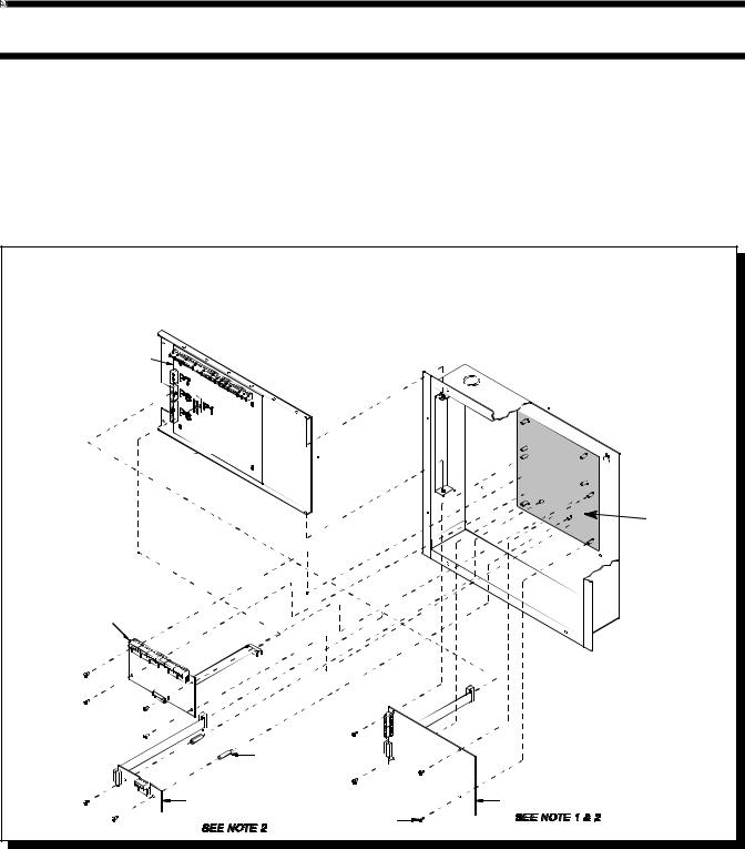
5.0 MODULE MOUNTING LOCATIONS
The FW-C2Z, FW-C4Z and FW-C4EZ fire alarms come pre-assembled with all components and boards, except for Adder Modules. Module installation locations are shown below.
Be sure to connect a solid Earth Ground (from building system ground / to a cold water pipe) to the Chassis Earth Ground Mounting Lug, and to connect the Earth Ground Wire Lugs from the Main Chassis to the ground screw on the Backbox.
Note that a CH-429 Accessory Mounting Plate is required for the FW-C2Z, or FW-C4Z if any Adder Module is to be used. Note that only one of FW-RB4, FW-RB8, FW-RPM, or FW-DACT Modules may be used. The CH-429 is installed so that the one Module being used is towards the bottom of the enclosure.
Fig.3: FW-C2Z, FW-C4Z Module Mounting Locations
NOTES:
1.THE CH-429 ACCESSORY MOUNTING PLATE MUST BE INSTALLED SO THAT THE MODULE BEING USED IS INSTALLED TOWARDS THE BOTTOM OF THE ENCLOSURE. THIS IS AS SHOWN FOR THE FW-DACT OR FW-RPM AND ROTATED 180 DEGREES FOR THE FW-RB4 OR FW-RB8.
2.ONLY ONE OF FW-DACT, FW-RPM, FW-RB4, OR FW-RB8 MAY BE INSTALLED
MAIN FIRE
ALARM MODULE
 BACKBOX
 DISPLAY PLATE
CH-429
ACC. MOUNTING
PLATE
RELAY MODULE (NOTE 1 & 2)
#6-32 x 7/8" |
|
M/F HEX SPACER |
|
POLARITY REVERSAL AND |
DIALER MODULE |
CITY TIE MODULE |
(MODEL FW-DACT) |
(MODEL FW-RPM) |
#6-32 x 1/4" |
SCREW
36

Fig.4: FW-C4EZ Module Mounting Locations
NOTES:
1.RELAY MODULE MAY BE FW-RB4 OR FW-4B8
2.ONLY ONE OF FW-DACT OR FW-RPM MAY BE INSTALLED
|
MAIN FIRE |
|
ALARM |
ZONE ADDER |
MODULE |
|
|
MODULE |
BACKBOX |
(FW-EZM4) |
|

 DISPLAY
PLATE
RELAY MODULE (NOTE 1)
#6-32 x 7/8" |
|
M/F HEX SPACER |
|
POLARITY REVERSAL AND |
DIALER MODULE |
CITY TIE MODULE |
(MODEL FW-DACT) |
(MODEL FW-RPM) |
#6-32 x 1/4" |
SCREW
Page 11 of 36
 Loading...