

Page 1

SERVICE MANUAL
SERVICE MANUAL
MODEL : M5 C/AH
© NAD 2006
NAD ELECTRONICS INTERNATIONAL
TORONTO
CD/SACD PLAYER
M5 C/AH
SERVICE MANUAL
M5 C/AH
M5 C/AH
CD/SACD PLAYER
CD/SACD PLAYER
Page 2
CONTENTS
SECTION 1 SUMMARY
SECTION 3 ELECTRICAL
SECTION 2 CABINET & MAIN CHASSIS
SECTION 4 MECHANISM
SECTION 5 REPLACEMENT PARTS LIST
SECTION 1 . . . .SUMMARY
SECTION 2 . . . .CABINET & MAIN CHASSIS
SECTION 3 . . . .ELECTRICAL
SECTION 4 . . . .MECHANISM
SECTION 5 . . . .REPLACEMENT PARTS LIST
Page 3

SECTION 1 SUMMARY
CONTENTS
PRODUCT SAFETY SERVICING GUIDELINES FOR AUDIO PRODUCTS
SERVICING PRECAUTIONS ........................................................................... 1-3
• General Servicing Precautions
• Insulation Checking Prodedure
• Electrostatically Sensitive Devices
SPECIFICATIONS
...........................................................................................
............. 1-2
1-4
1-1
Page 4
PRODUCT SAFETY SERVICING GUIDELINES FOR AUDIO PRODUCTS
CAUTION : DO NOT ATTEMPT TO MODIFY THIS
PRODUCT IN ANY WAY, NEVER PERFORM CUSTOMIZED INSTALLATIONS WITHOUT MANUFACTURER’S
APPROVAL. UNAUTHORIZED MODIFICATIONS WILL
NOT ONLY VOID THE WARRANTY, BUT MAY LEAD TO
YOUR BEING LIABLE FOR ANY RESULTING PROPERTY DAMAGE OR USER INJURY.
SERVICE WORK SHOULD BE PERFORMED ONLY
AFTER YOU ARE THOROUGHLY FAMILIAR WITH ALL
OF THE FOLLOWING SAFETY CHECKS AND SERVICING GUIDELINES. TO DO OTHERWISE,INCREASES
THE RISK OF POTENTIAL HAZARDS AND INJURY TO
THE USER.
WHILE SERVICING, USE AN ISOLATION TRANSFORMER FOR PROTECTION FROM A.C. LINESHOCK.
SAFETY CHECKS
AFTER THE ORIGINAL SERVICE PROBLEM HAS
BEEN CORRCTED. A CHECK SHOULD BE MADE OF
THE FOLLOWING.
SUBJECT : FIRE & SHOCK HAZARD
1.BE SURE THAT ALL COMPONENTS ARE POSI-
TIONED IN SUCH A WAY AS TO AVOID POSSIBILITY
OF ADJACENT COMPONENT SHORTS.THIS IS ESPECIALLY IMPORTANT ON THOSE MODULES WHICH
ARE TRANSPORTED TO AND FROM THE REPAIR
SHOP.
2. NEVER RELEASE A REPAIR UNLESS ALL PROTECTIVE DEVICES SUCH AS INSULATORS, BARRIERS,
COVERS, SHIELDS, STRAIN RELIEFS, POWER
SUPPLY CORDS, AND OTHER HARDWARE HAVEBEEN REINSTALLED PER ORIGINAL DESIGN. BE
SURE THAT THE SAFETY PURPOSE OF THE POLARIZED LINE PLUG HAS NOT BEEN DEFEATED.
3. SOLDERING MUST BE INSPECTED TO DISCOVER
POSSIBLE COLD SOLDER JOINTS, SOLDER
SPLASHES OR SHARP SOLDER POINTS. BE CERTAIN TO REMOVE ALL LOOSE FOREIGN PARTICLES.
4. CHECK FOR PHYSICAL EVIDENCE OF DAMAGE
OR DETERIORATION TO PARTS AND COMPONENTS.
FOR FRAYED LEADS, DAMAGED INSULATION
(INCLUDING A.C. CORD). AND REPLACE IF NECES-
5. NO LEAD OR COMPONENT SHOULD TOUCH A
RECIVING TUBE OR A RESISTOR RATED AT 1 WATT
OR MORE. LEAD TENSION AROUND PROTRUNING
METAL SURFACES MUST BE AVOIDED.
6. ALL CRITICAL COMPONENTS SUCH AS FUSES,
FLAMEPROOF RESISTORS, CAPACITORS, ETC.
MUST BE REPLACED WITH EXACT FACTORY TYPES,
DO NOT USE REPLACEMENT COMPONENTS OTHER
THAN THOSE SPECIFIED OR MAKE UNRECOMMENDED CIRCUIT MODIFICATIONS.
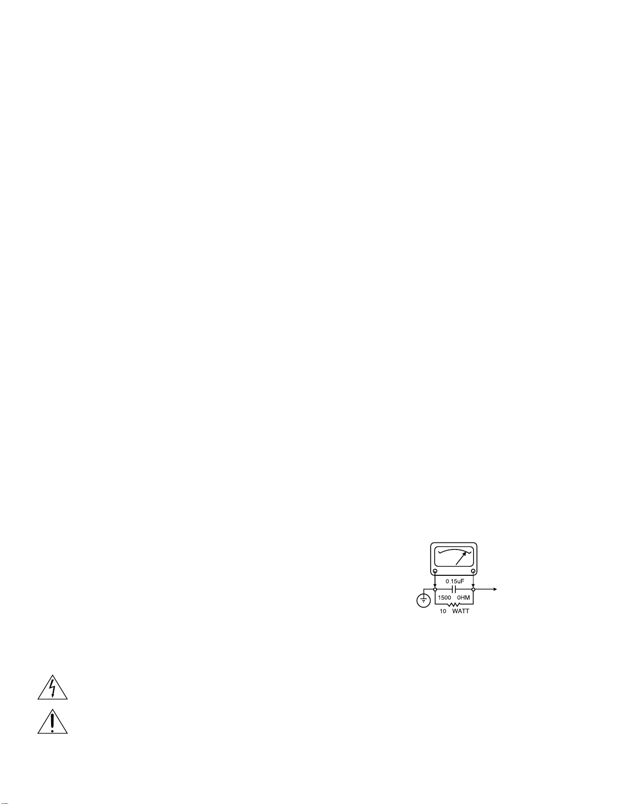
7. AFTER RE-ASSEMBLY OF THE SET ALWAYS PERFORM AN A.C. LEAKAGE TEST ON ALL EXPOSED
METALLIC PARTS OF THE CABINET, (THE CHANNEL
SELECTOR KNOB, ANTENNA TERMINALS. HANDLE
AND SCREWS) TO BE SURE THE SET IS SAFE TO
OPERATE WITHOUT DANGER OF ELECTRICAL
SHOCK. DO NOT USE A LINE ISOLATION TRANSFORMER DURING THIS TEST USE AN A.C. VOLTMETER, HAVING 5000 OHMS PER VOLT OR MORE SENSITIVITY, IN THE FOLLOWING MANNER; CONNECT A
1500 OHM 10 WATT RESISTOR, PARALLELED BY A
.15 MFD. 150.V A.C TYPE CAPACITOR BETWEEN A
KNOWN GOOD EARTH GROUND (WATER PIPE,
CONDUIT,ETC.) AND THE EXPOSED METALLIC
PARTS, ONE AT A TIME. MEASURE THE A.C. VOLTAGE ACROSS THE COMBINATION OF 1500OHM
RESISTOR AND .15 MFD CAPACITOR. REVERSE THE
A.C. PLUG AND REPEAT A.C. VOLTAGE MEASUREMENTS FOR EACH EXPOSED METALLIC PART. VOLTAGE MEASURED MUST NOT EXCEED 75 VOLTS
R.M.S. THIS CORRESPONDS TO 0.5 MILLIAMP A.C
ANY VALUE EXCEEDING THIS LIMIT CONSTITUTES A
POTENTIAL SHOCK HAZARD AND MUST BE CORRECTED IMMEDIATELY.
A.C. VOLTMETER
GOOD EARTH GROUND
SUCH AS THE WATER
PIPE. CONDUIT. ETC
PLACE THIS PROBE
ON EACH EXPOSED
METAL PART
SUBJECT: GRAPHIC SYMBOLS
THE LIGHTNING FLASH WITH APROWHEAD SYMBOL. WITHIN AN EQUILATERAL TRIANGLE, IS INTENDED
TO ALERT THE SERVICE PERSONNEL TO THE PRESENCE OF UNINSULATED “DANGEROUS VOLTAGE”
THAT MAY BE OF SUFFICIENT MAGNITUDE TO CONSTITUTE A RISK OF ELECTRIC SHOCK.
THE EXCLAMATION POINT WITHIN AN EQUILATERAL TRIANGLE IS INTENDED TO ALERT THE SERVICE
PERSONNEL TO THE PRESENCE OF IMPORTANT SAFETY INFORMATION IN SERVICE LITERATURE.
1-2
Page 5

SERVICING PRECAUTIONS
CAUTION
this service data and its supplements and addends, read and
follow the SAFETY PRECAUTIONS. NOTE: if unforeseen
circumstances create conflict between the following servicing
precautions and any of the safety precautions in this publication,
always follow the safety precautions.
Remember Safety First:
General Servicing Precautions
1. Always unplug the Stereo amplifier AC power cord from the
AC power source before:
(1) Removing or reinstalling any component, circuit board,
(2) Disconnecting or reconnecting any internal electrical
(3) Connecting a test substitute in parallel with an electrolytic
Caution: A wrong part substitute or incorrect polarity
2. Do not spray chemicals on or near this Stereo amplifier or
any of its assemblies.
3.Unless specified otherwise in this service data, clean
electrical contacts by applying an appropriate contact
cleaning solution to the contacts with a pipe cleaner,
cottontipped swab, or comparable soft applicator.
Unless specified otherwise in this service data, lubrication
of contacts is not required.
4. Do not defeat any plug/socket B+ voltage interlocks with
which instruments covered by this service manual might be
equipped.
5. Do not apply AC power to this Stereo amplifier and/or any
of its electrical assemblies unless all solid-state device heat
sinks are correctly installed.
6. Always connect test instrument ground lead to the
appropriate ground before connecting the test instrument
positive lead. Always remove the test instrument ground lead
last.
Insulation Checking Procedure
Disconnect the attachment plug from the AC outlet and turn the
power on. Connect an insulation resistance meter (500V) to the
blades of the attachment plug. The insulation resistance
between each blade of the attachment plug and accessible
conductive parts (Note 1) should be more than 1 M-ohm.
Note 1: Accessible Conductive Parts including Metal panels,
Input terminals, Earphone jacks, etc.
: Before servicing the Stereo amplifier covered by
module, or any other assembly.
plug or other electrical connection.
capacitor.
installation of electrolytic capacitors may result in an
explosion hazard.
Electrostatically Sensitive (ES) Devices
Some semiconductor (solid state) devices can be damaged
easily by static electricity. Such components commonly are
called Electrostatically Sensitive (ES) Devices. Examples of
typical Es devices are integrated circuits and some field effect
transistors and semiconductor chip components.
The following techniques should be used to help reduce the
incidence of component damage caused by static electricity.
1. Immediately before handing any semiconductor component
or semiconductor-equipped assembly, drain off any
electrostatic charge on your body by touching a known earth
ground. Alternatively, obtain and wear a commercially
available discharging wrist strap device, which should be
removed for potential shock reason prior to applying power to
the unit under test.
2. After removing an electrical assembly equipped with ES
devices, place the assembly on a conductive surface such as
aluminum foil, to prevent electrostatic charge buildup or
exposure of the assembly.
3. Use only a grounded-tip soldering iron to solder or unsolder
ES devices.
4. Use only an antistatic solder removal device. Some solder
removal devices not classified a “anti-static” can generate
electrical charges sufficient to damage ES devices.
5. Do not use freonpropelled chemicals. These can generate
electrical charge sufficient to damage ES devices.
6. Do not remove a replacement ES device from its protective
package until immediately before you are ready to install it.
(Most replacement ES devices are packaged with leads
electrically shorted together by conductive foam, aluminum
foil, or comparable conductive material).
7. Immediately before removing the protective material from the
leads of a replacement ES device, touch the protective
material to the chassis or circuit assembly into which the
device will be installed.
Caution: Be sure no power is applied to the chassis or circuit,
and observe all other safety precautions.
8.Minimize bodily motions when handing unpackaged
replacement ES devices. (Normally harmless motion such as
the brushing together of your clothes fabric or the lifting of
your foot from a carpeted floor can generate static electricity
sufficient to damage an ES device.)
1-3
Page 6

SPECIFICATIONS
•GENERAL
Power requirements: AC 100-240 V , 50/60 Hz
Power consumption: 45W
Dimensions (Approx.): 435 x 100 x 300 mm (W xHxD)without foot
Weight (Approx.): 8.6 kg
Operating temperature: 5 °C to 35 °C (41 °F to 95 °F)
Operating humidity: 5 % to 90 %
• OUTPUTS
VIDEO OUT: 1 Vp-p 75 sync negative, RCA jack x 1
AUDIO OUT: 2.0 Vrms (1 KHz, 0 dB),
60 &+8QEDODQFH%DODQFH
PXWL&+
RCA jack (L, R) x 1/ XLR jack (L, R) x 1/ RCA jack(6-ch) x 1
DIGITAL OUT (COAXIAL): 0.5 V (p-p), 75 RCA jack x 2SWLFDO[ 1,AES/EBU x 1
• System
Laser:
6LJQDO system:
Frequency response:
SLJQDO-to-noise ratio(A-W): More than 110 dB (2CH ANALOG OUT )
Harmonic distortion: Less than 0.005%
Dynamic range: More than
• Accessories
Video FDEOe (1), Audio FDEOe (1), Remote controO (1), Batteries (2)
Semiconductor ODVer, ZDYHOHQgth 650 nm
PAL / PAL 6 0 / NTSC
SACD:8Hzto50kHz
CD: 8 Hz to 20 kHz
More than 100 dB (muti-CH ANALOG OUT )
95dB (CD/SACD muti-ch)
More than 105dB (SACD 2-ch)
1-4
Page 7

SECTION 2 CABINET & MAIN CHASSIS
CONTENTS
EXPLODED VIEWS................................................................................................................ 2-2
1. Cabinet and Main Frame Section ................................................................................ 2-2,3
2. Exploded view parts list......
3. Packing accessory section............................................................................................2-5
.................................................................................................. 2-4
2-1
Page 8
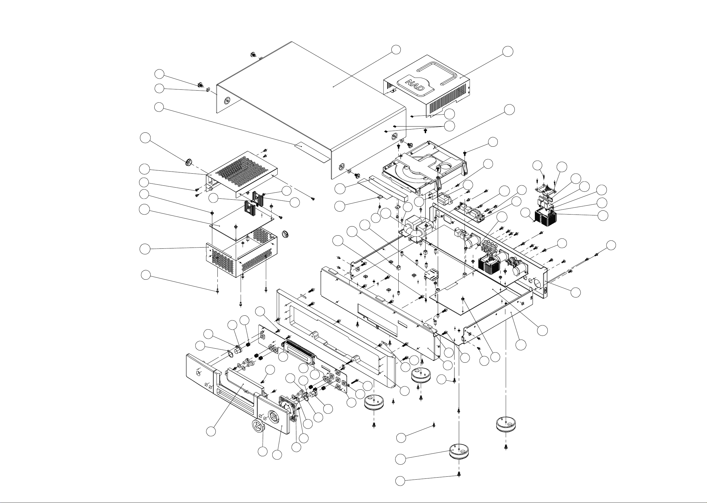
EXPLODED VIEWS
1.Cabinet and main frame section
S021
T003
T002
C009
C008
S013
S010
C007
C006
S012
S014
P001
C014
C013
C010
C011
C012
S015
C005
T001
S011
R003
C017
C016
R002
S019
S016
C004
C003
C016
C015
RS01
S008
S018
S017
A001
S020
A002
A003
A004
A003
A005
S008
S012
F007
F008
F003
F009
F010
S001
F002
S001
F001
FP01
F011
F004
FP02
F012
S002
F005
FP03
F006
F013
F014
S003
S004
S008
C016
F016
F015
S005
S008
F018
F017
S006
S007
R001
C002
C001
S010
2-2
S009
2-3
Page 9
2.EXPLODED VIEW PARTS LIST
REF.NO. PART NO. DESCRIPTION Qty. REF.NO. PART NO. DESCRIPTION Qty.
New PN 67-051002-1
C002 01-50501-00 Decode Board 1 T002 86-018002-1 Expanded Rubber 2
C003 01-50502-00 Audio Board 1 T003 76-046001-0 Screw Washer 4
C004 01-50505-00 RS232 Board 1
C005 18-55017-20 R Type Transformer(C Version) 1
18-55017-10 R Type Transformer(AH Version) 2tekcarB0-010010-6610SR1
C006 68-051002-1 Shielding Box(down) 1
C008 68-051001-1 Shielding Box(up) 1
C009 85-051001-0 Snap Bushing 2 A003 01-50506-01 Module Board 4
C010 85-051002-0 PCB Spacer 3 A004 78-048004-0 Insulated Cushion 8
C017 69-051004-0 Loader Clamp 2 2
C018 68-051003-0 Loader Cover 1
C019 83-043001-0 Foot Assembly 4
F003 76-051001-0
F004 77-051001-1 Cursor Holder 1 S005 61-224512-1 Hex Head Screw (M4X12) 6
F005 87-048002-0 Input Button Pad 4 S006 61-224508-1 Hex Head Screw (M4X8) 7
F006 87-048003-0 Power Button Pad 2 S007 61-063106-0 Self Taping Screw (STF3X6) 4
F007 86-046001-0 Led Lens Gum 1 S008 61-023106-2 Self Taping Screw (STB3X6) 17
F009 70-048013-0 Power Button 1
F010 92-048001-0 Spring for Button 6 S011 61-023506-1 Machine Screw(MB3×6-Ni) 4
F012 70-051006-1 Stop-Menu Button 2
F016 86-046002-0 Fascia Padding 2
F018 86-010004-0 3mm Rubber Pad 3 S019 61-073108-0 Self Taping Screw (STO3X8) 2
R001 67-051003-0 Rear Panel (C Version) 1 S021 61-246508-0 Machine Screw (MB6X8-Cr) 4
67-051005-0 Rear Panel (AH Version) 1
R003 11-01101-03 Rocker Switch 1
VFD window 1 S004 61-023616-0 Self Taping Screw (TBBT3×16) 2
A002 66-048001-0 Module Tr. Braccket 4
1pmalCeniL0-200150-57210C
1rooDDVD1-100150-07410C
FP03 75-051001-0 Display Bracket 1
S001 61-023206-1 Self Taping Screw (BTB3X6) 7
(rehsaW0-503011-36300S1rosruCgniR0-200150-07200F 3× 7×0.5 2
S010 61-373506-0 Machine Screw (MB3X6W.S-Ni) 11
S013 61-023106-1 Self Taping Screw (STB3X6-Ni) 6
S017 61-062206-1 Self Taping Screw (BTF2×6) 8
S020 61-023208-0 Self Taping Screw (BTB3X8) 11
1telnICA20-20070-71200R
1revoCpoT0-200150-76100T1sissahC0-200760-76100C
2revoCeludoM0-100840-07100A1draoBUSP00-30505-10700C
2esaBeludoM1-100760-07500A4recapS2-200150-96110C
2knistaeH0-500150-07100P2pmalCrooDDVD0-200150-66310C
1tekcarBRI0-110150-5610PF1redaoL00-63880-73510C
1DFV00-95555-3220PF41pmalCredaoL0-300150-96610C
2)iN-6X5.2BM(wercSenihcaM6-605220-16200S12aicsaF0-400150-07100F
4)8X4BTS(wercSgnipaTfleS1-801420-16900S1sneLdeL0-100800-67800F
6)8X3BM(wercSenihcaM0-805320-16210S2nottuBtupnI1-210840-07110F
2)3M(tuN2-203010-26410S1nottuBretnE0-700150-07310F
2)iN-4X3BM(wercSenihcaM1-405320-36510S1PPF00-40555-10410F
4)8X3WPTS(wercSgnipaTfleS0-801380-16610S11aicsaF1-300160-07510F
4)8×2FTS(wercSgnipaTfleS1-801260-16810S1aicsafbuS1-100150-76710F
2-4
Page 10
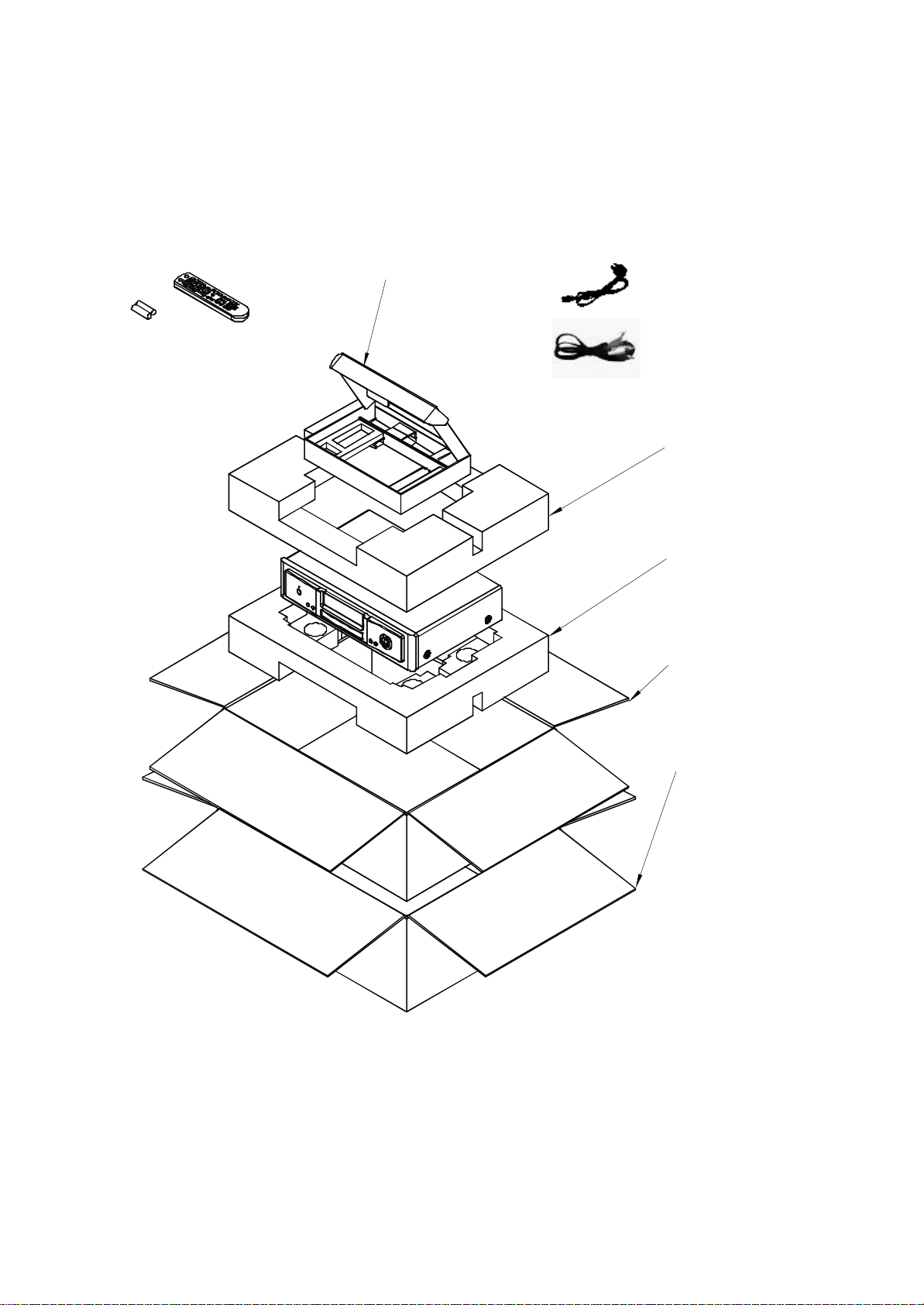
3.PACKING ACCESSORY SECTION
Batteries
REMOCON
Accessory Box
AC Cord
Audio and Video Cord
Polyfoam(up)
Polyfoam(down)
Gift Box
Shipping Box
2-5
Page 11

SECTION 3 ELECTRICAL
CONTENTS
ELECTRICAL TROUBLESHOOTING GUIDE
1. Power check flow………………………………………………………………………3-2
2. System operation flow…………………………………………………………………3-3
3. Test & debug flow……………………………………………………………………... 3-4,9
DETAILS AND WAVEFORMS ON SYSTEM TEST AND DEBUGING
1. System 27MHz clock,reset,flash R/W signal………………………………………..3-10
2. SDRAM clock…………………………………………………………………………..3-11
3. TRAY OPEN/CLOSE signal…………………………………………………………..3-11
4. SLED control related signal(NO disc control)……………………………………....3-12
5. LENS control related signal(NO disc control)……………………………………… 3-13
6. FOCUS control related signal(NO disc control)…………………………………… 3-14
7. SPINDLE control WAVEFORM……………………………………………………… 3-15
8. FOCUS ON WAVEFORM……………………………………………………………. 3-16
9. RF WAVEFORM…………………………………………………………….…………3-17
10. ES6168F Audio optical and coaxialoutput(SPDIF)………………………………. 3-17
11. ES6168F Video output to Audio DAC……………………………………….……..3-18
12. Audio output(1KHz odB)……………………………………………………….…… 3-18
BLOCK DIAGRAMS
1. Overall block diagram………………………………………………………………… 3-19
2. Power(SMPS) block diagram…………………………………………………………3-20
3. Servo block diagram………………………………………………………………….. 3-21
CIRCUIT DIAGRAMS
1. Power(SMPS) circuit diagram……………………………………………………….. 3-22
2. Decode board-ES6168 section……………………………………………………....3-23,24
3. Decode board-DSP section………………………………………………………......3-25,26
4. Decode board-H-POWER & DRIVER section……………………………………...
5. Decode board-RF section……………………………………………………………. 3-28
6. Decode board-CONNECT AND 232 section…………………………………........ 3-29
7. Audio board…………………………………………………………………............... 3-30,31
8. 232 AND AMP module board………………………………………………………...3-32
9. Front panel board…………………………………………………………………….....3-33
CIRCUIT VOLTAGE CHARGE
PRINT CIRCUIT BOARD DIAGRAM
1. Decode board………………………………………………………………….............3-42,43
2. Audio board………………………………………………………………………….....3-44,45
3. SMPS board………………………………………………………………………....... 3-46
4. Front panel board……………………………………………………………………...3-47,48
5. RS232 board……………………………………………………………………….......3-47,48
6. AMP module board…………………………………………………………………… 3-47,48
………………………………….…………………........3-34,41
3-27
3-1
Page 12
ELECTRICAL TROUBLESHOOTING GUIDE
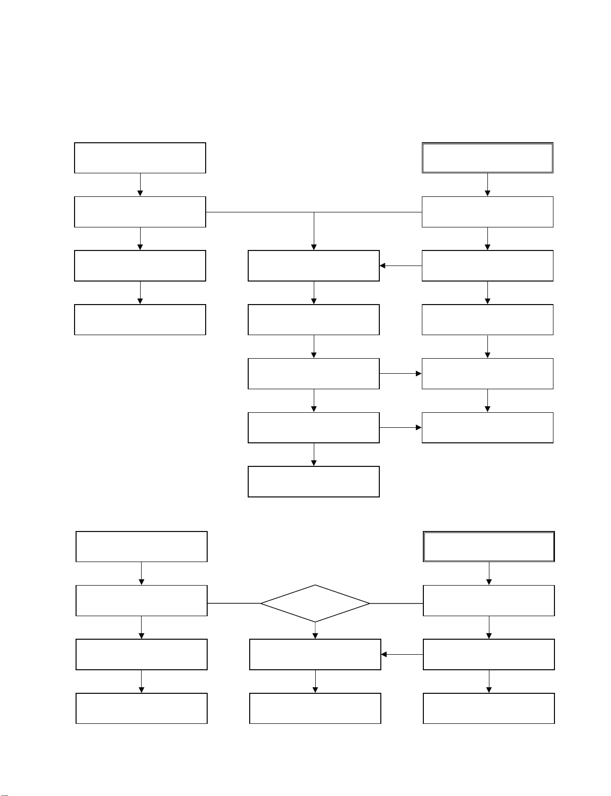
1.
Power check flow
Digital circuit supply
A.
No VF+
Is 5VD section working?
YES
Check D910
No
Replace D910
NO
No 5VD
Check FH900
Is there a AC voltage at
one terminal of RT900?
YES
Is there a DC voltage At
(+) terminal of B900?
YES
B.
No 5VS
NO
Is 5VD section working?
YES
NO
Is 5VD present at input
of U911?
YES
Replace U911.
YES
NO
NO
Replace RT900.
YES
Replace B900.
Analog circuit supply
A.
No +/-12V
Is +/-VCCA works well?
YES
Check U605 U606
Replace U605/U606
NO
Replace U900.
Is 5VD right
Yes
Check Q619 Q621 Q623
Yes
Check Transformer
3-2
B.
No 5VA
NO
Is VM works well
YES
NO
Check U658
YES
Replace U658.
Page 13
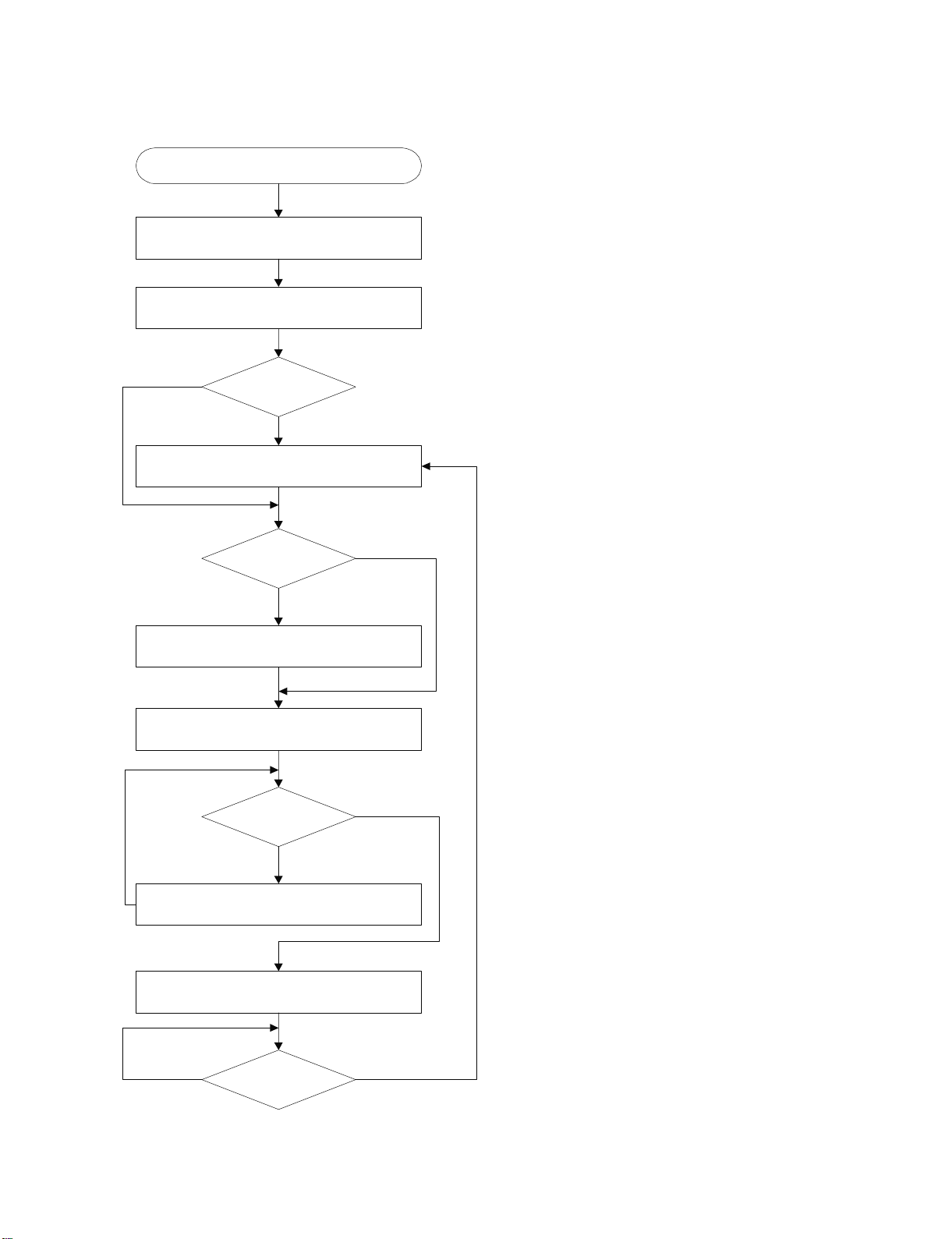
2. System operation flow
Power On
1. ES6168 initializes SERVO & the other DSPs
Show LOGO
YES
Tray Closed?
NO
Tray Close to Closed position
SLED at Inner
Side ?
NO
SLED Moves to Inner Positi on
1. Judge whether have disc and disc type
2. Jump to related disc reading procedure
Reci eve
OPEN/CLOSE
Key?
YES
YES
NO
1. Execute Pressed Key & IR Key
2. System operation Routine Loop
1. Stop Playback & Open Tray
2. Display tray open message & LOGO
NO
Receive
CLOSE Key?
YES
3-3
Page 14
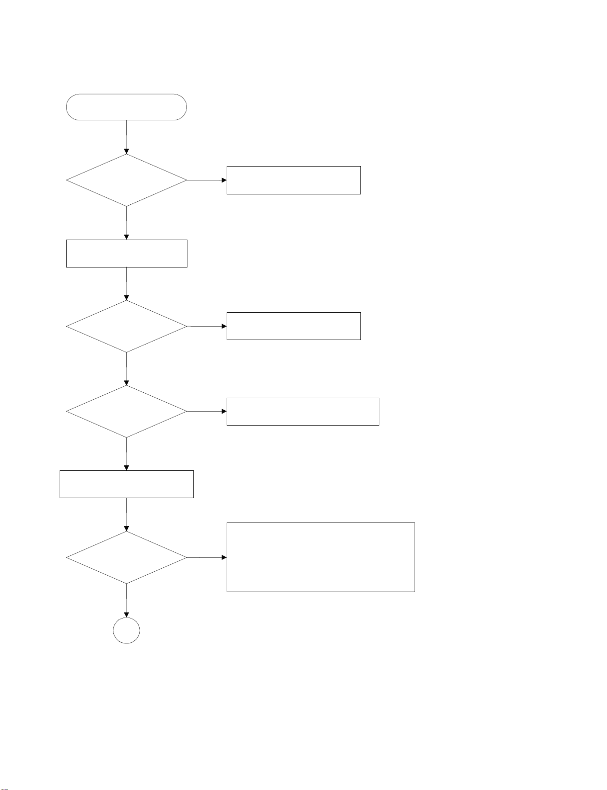
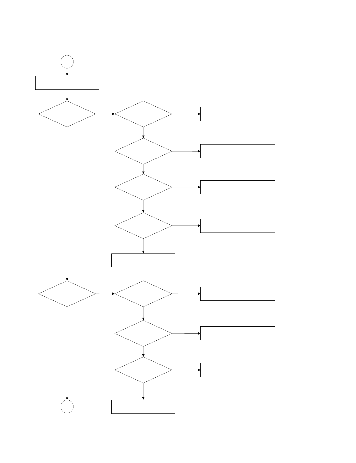
3. Test & debug flow
Switch on the Power switch
Check the AC Voltage on
Power PCB (110V or 220V)
YES
Press the power key on front panel
Is the DC Voltage
outputs OK?
(5V,3.3V,9V,±12V,5VA)
YES
Is 3.3V,1.8V and 2V DC
outputs normal on decode
PCB?
YES
NO
NO
NO
Check Fuse and connections
to AC inlet
Repair or Replace Power PCB
Replace R-core Transformer
Check the regulators or related diodes.
Insert the upgrade disc to update
the FLASH memory code.
Update FLASH
successfully?
YES
A
NO
1. Check 27MHz system clock.
2. Check system reset circuit.
3. Check FLASH R/W enable signal LOE#,WRLL.
4. Check servo related circuit.
5. Check FLASH Memory related circuit.
3-4
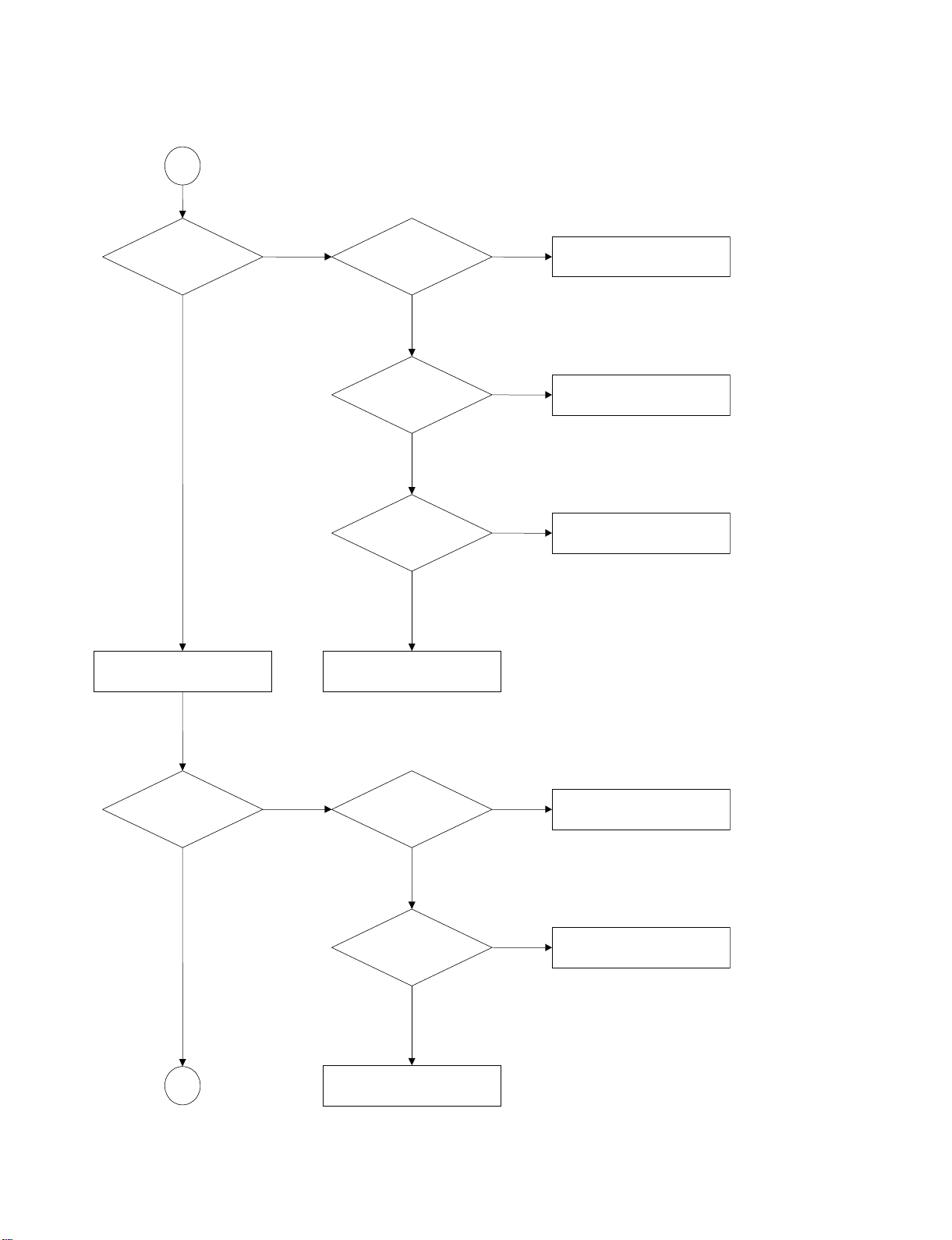
Page 15
A
RESET or Power On.
Show LOGO?
NO
Flash Memory operates
properly?
YESYES
SDRAM works properly?
YES
ES6168
Video PINs outputs
properly?
YES
Have TV signal output?
YES
Check AV cable connection
to TV set.
NO
NO
NO
NO
Check connection lines between FLASH
& ES6168 and the FLASH access time
whether is suitable or not.
Check connection lines between
SDRAM & ES6168 and the SDRAM
is damaged.
Check the related ICs
Check the filtering circuit of
TV signal.
Does Tray move
inside when it is not
at closed position?
YES
B
NO NO
Normal OPEN_SW&
CLOSE_SW signals?
YES
Normal LDM1 &
LDM2 signal?
YES
Normal EJ+ & EJ-
signal?
YES
Check the cable connection
between decode PCB and loader.
NO
NO
3-5
Check the load OPEN & CLOSE
switch
Check the Tray control IO pins on
CXD1885 & FAN8042.
Check the Tray control amplifying
circuit on Motor driver.
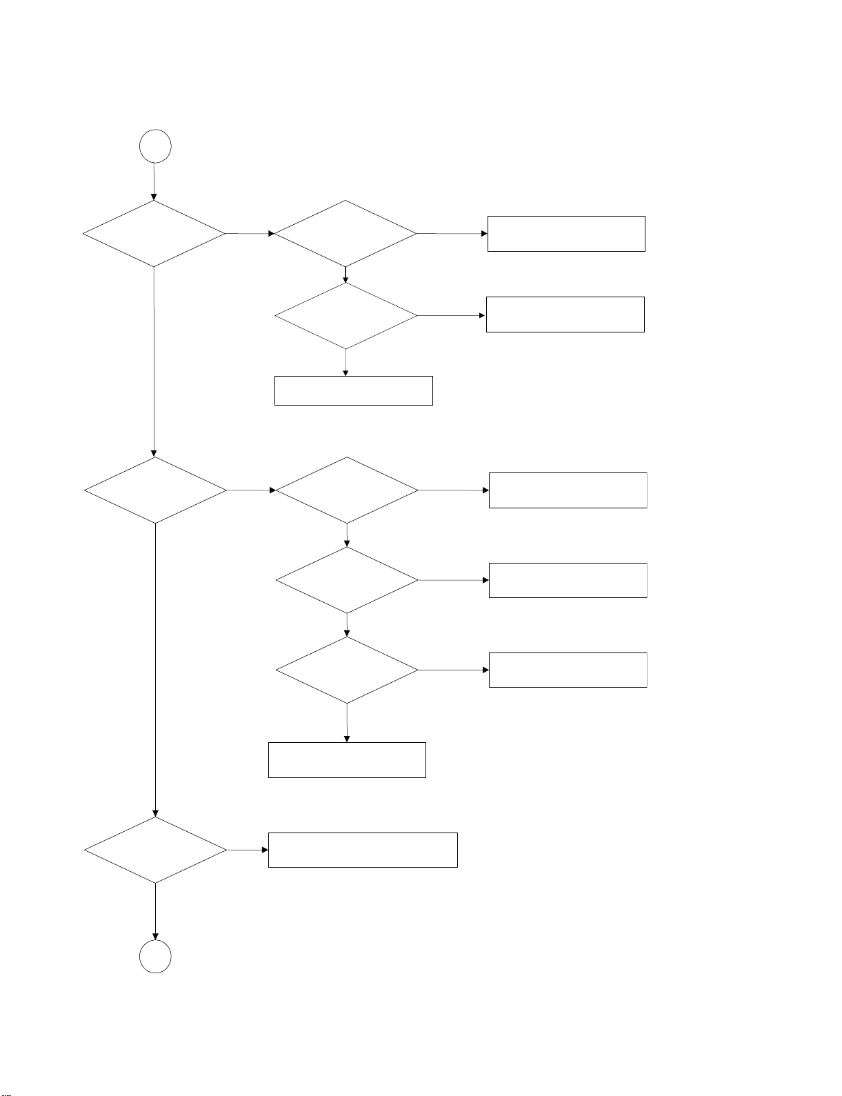
Page 16
B
Does
the SLED move
to inner side when it is at
outter position?
Do not put in disc and tray
close.
Motor Driver
XFTSMUTE
Pin is High?
SEYSEY
Is SLED DC Level lower
than 1.65V?
YES
SL+ and SL- output
properly?
YES
Check the cable connection with
MECHA.
NO
NO
ONON
Check the connection line of
XFTSMUTE signal.
Check the related circuit of
SLED.
Check the amp circuit on motor
driver.
Optical Lens has
movements for searching
Focus?
C
Proper FSCON outputs
to motor driver?
YESYES
Proper F+ & F- outputs?
YES
Check cable connect on with
pick-up head.
3-6
NO
ONON
Check FSCON connection on
CXD1885Q and motor dirver.
Check the amp circuit on motor
dirver.
Page 17

C
Laser turns on when
reading disc?
YES
YES
Disc ID is correct?
NO
NO
NO
DVDLD or CDLD
output properly?
YES
Collector voltage of
power transistor is OK?
YES
Check cable connection between
transistor ouput and pick-up
head.
fforesaL?nicsidtuP
Proper RFSIN signal
on CXD1881?
YES
NO
NO
NO
Check the laser power circuit
on CXD1881 and connecting to
power transistor.
Check the related circuit on
laser power transistor
Check the related circuit
on CXD1881 RFSIN signal.
YES
Does spindle rotate?
YES
D
NO
Check DVDLD & CDLD signal
Proper SPWM signal on
CXD1885Q
YES
SP+ & SP- output
properly?
YES
Check the cable connection
between spindle and main PCBA.
NO
NO
Check SPWM related
circuit on CXD1885Q.
Check the spindle control
amp circuit of motor
driver.
3-7
Page 18
D
YES
Focus ON OK?
YES
Track On OK?
YES
NO NO
NO
Proper signals on
A,B,C,D of CXD1881
YES
Check FEO signal
on CXD1881
YES
Check FSCON signal
on CXD1885Q
Normal TEO Signal on
CXD1881 ?
YES
Properly TSCON
signal on CXD1885Q?
YES
NO
NO
NO
Check connections between
CXD1881 and pick-up head.
Check the FSCON connection on
CXD1885Q and motor driver.
Check the related
circuit on CXD1881
Check the TSCON
connection on CXD1885Q
and motor dirver.
Disc is play ?
YES
E
NO
T+ & T- output
properly?
YES
Check cable connection on
pick-up head.
Check RF-OP & RFAC signal waveform.
NO
3-8
Check the tracking control
amp circuit on motor
driver.
Page 19

E
Normal Audio output
when disc playback?
YES
Normal IR.VFD & Front
pannel key functions?
YES
TEST END
NO NO
NO
Audio DAC received
correct data stream?
YES
Normal Audio DAC
out?
YES
Check Audio filter,amplify,mute
ES6168 is normally
Check the cable connection on
circuit.
Communications between
IR.VFD Front pane
Front pannel.
YES
lkey &
l
?
NO
NO
Check connection between ES6168
& CXD2753 & Audio DAC.
Check the related
circuit of Audio DAC.
Check communication lines on
ES6168.
3-9
Page 20

DETAILS AND WAVEFORMS ON SYSTEM
TEST AND DEBUGGING
1.SYSTEM 27MHz CLOCK, RESET, FLASH R/W SIGNAL.
1) ES6168F main clock is at 27MHz(pin49)
2) ES6168F( pin24) reset is low active.
FIG 1-1
Ch1 VCC
CH2 RESET
FI1-2
3-10
Page 21

2. SDRAM CLOCK
FIG 2-1
3. TRAY OPEN/CLOSE SIGNAL
CH1 EJ-
CH2 EJ+
FIG 3-1
3-11
Page 22

CH1 EJ-
CH2 EJ+
FIG 3-2
4. SLED CONTROL RELATED SIGNAL(NO DISC CONDITION)
SLED CONTROL
FIG 4-1
FIG 4-2
CH1 SL+
CH2 SL-
3-12
Page 23

5. LENS CONTROL RELATED SIGNAL(NO DISC CONDITION)
LDON
FIG 5-1
FIG 5-2
CH1 DVD_LD
CH2 CD_LD
3-13
Page 24

6. FOCUSE CONTROL RELATED SIGNAL(NO DISC CONDITION)
FSCON
FIG 6-1
CH1 FOCUS-
CH2 FOCUS+
FIG 6-2
3-14
Page 25

7. SPINDLE CONTROL WAVEFORM
CH1 SPWM2
CH2 SPWM1
FIG 7-1(DVD)
FIG 7-2(CD)
CH1 SPWM2
CH2 SPWM1
3-15
Page 26

8. FOCUS ON WAVEFORM(FSCON)
FIG 8-1(CD)
FIG 8-2 (SACD)
3-16
Page 27

9. RF WAVEFORM
),*&'
),*6$&'
10.ES6168F AUDIO OPTICAL AND COAXIAL OUTPUT (SPDIF)
),*
3-17
Page 28

11. ES6168F AUDIO OUTPUT TO AUDIO DAC
FIG 11-1
CHI1 BITCLOCK
CH2 LRCLOCK
12. AUDIO OUTPUT (1KHZ 0DB)
FIG 12-1
3-18
Page 29

RF AMP CXD1881
DVD SERVO CXD1885
DSD DECODER CXD2753
ESS 6168
IC 25 FAN8042
Motor Driver
IC18
IC21
IC25
IC16
Pick Up
M
M
M
DSIC
POWER
BOARD
AC 100V-240V
50Hz/60Hz
VF+
VF-
-22VA
-15V
+15V9V3.3VD
5VS
IC20
4Mbit EDO
X4
33.8688MHz
IC17
CPLD
Y3
27MHz
U13
U14
EEPROM
SCL, SDA
SDRAM
64M
DQM0,DQM1
DQ[0:15]
DCLK,WE,CAS,RAS
CS,DCKE,MA[0:11]
U6
FLASH MEMORY
(16M)
A[0:19]
PWR,PCE,PRD
AD[0:7]
U652
AUDIO DAC
5.1CH
AMP OPA2134UA
U653-U655
ML MR
FLFR
SL SR
CENTERSUB
MLMR
FL FR
SLSR
CENTER SUB
SPINDLE[+,-]
SLED[+,-]
LOAD[+,-]
IC15
M12L1616A-7T
DCKE
DCLK
A[0:11] DSD
T+,T-F+,F-
ABCDEF
LMT SW
OPN SW
CLS SW
LD M1
LD M2
RA[0:9]
RD[0:15]
VDT[0:7]
XSAK
SDEF
XSHD
PLCK
SDCK
DSAR
DSAL
DSALS
DSDASW
DSAC
DSARS
U10
DD[0:7]
RFAC
AMPSEN
AMPSDT
AMPSCK
DFCT
MIRR
RFAC
TEO
FEO
PI
U20
SC16C550IB18
RS232
Y3
1.8432MHz
AUX5
LA2
LA1
LA0
U21
MAX3221
HTXD
HRXD
RS232
JACK
P1
RXD
TXD
PT6311
U801
KEY INPUT
VFD DATA
VFD CLK
VFD CS
FLD DISPLAY
POWER CONTROL
U3
74HC86
IR PHONE
U802
HS0038B
IR IN
IR RECEIVER
COAXIAL
SPDIF
SW503
J501A
OFF
ON
TRIG O/F
+12V O/F
BLOCK DIAGRAM
1.OVERAL BLOCK DIAGRAM
IR
U604
AUDIO DAC
2CH
U601-U602
AND NAD AMP
MODULE
DSD ML MR
PCM ML MR
IICBUSS
IICBUSS
VIDEO OUT
VIDEO OUT
3-19
Page 30

2.POWER(SMPS)BLOCK DIAGRAM
POWER CONTROL
F+F--22VA
5VD
3.3VD
REG(3.3V)
LPF
+9VS
REG(9V)
LPF
5VS
REG(5V)
GND
LPF
RECTIFIER(FLD)
RECTIFIER(3.3V)
RECTIFIER(9.6V)
RECTIFIER(5.7V)
FEED.B
TRANS
SWITCHING IC
LINE FILTERRECTIFIER
AC 100-240V
3-20
Page 31

3.SERVO Block Diagram
DFCT
MIRR
IC21
IC20
RFAC
4MBit EDO
IC18
PI
FBO
TEO
RF AMP CXD1881
DVD SERVO CXD1885
LIMIT,TRIN,TROUT
IC17
CPLD
X4
33.8688MHz
IC16
DSD DECODER CXD2753
ADIN
STBY
FOSO,TRSO
DMSO,TROPEN,TRCLOSE
IC25
Motor Driver
IC 25 FAN8042
V20,PICKSEL
MDL1
F+,F-,T+,T-
LD01,LDO2,IOA
PICK UP
DVD:A,B,C,D,RFO
CD:A,B,C,D,E,F,RFO
3-21
SL+,SL-
SP+,SP-
M/D
LOAD+,LOAD-
Page 32

CIRCUIT DIAGRAMS
1.POWER(SMPS) BOARD
+15V
-15V
SGND
AGND
13
+VCCA
12
DGND
5VD
10
11
DGND
9
3.3VD
8
STB
5VS
7
5
6
+12V
-VCCA
14
15
J906
+9VS
4
-22V
VF+
VF-
1
2
3
CON15*2MM
+VCCA
+5VD
3.3VD
STB
+5VS
VF-
VF+
10K
R957
10K
R954
R956
10K
Q921
C1815
R955
10K
+5VD
10K
R944
Q907
A1015
+5VD
10K
10K
R942
R943
Q906
C1815
Q900
C1815
-22V
C949
47u/50V
5.6V
D911
D910
FR104
D912
FR205
10
12
11
+3.3VV
+3.3VV
2
3
g
Vd
Vo
U910
Vi
KA278R33
1
10k
R958
L906
22uH
C950
100u/50V
D913
SR340/SR360
14
15
16
13
+5VD
3.3VD
C964
0.1u
3.3VD
C956
2
3
100u/16V
g
Vd
Vo
R951
10K
4
Vi
1
R953
10K NA
U909
KA278R33
C955
470u/25V
C954
1000U/16V
D909
SR504
18
17
VF-
STB
VF+
-22V
+5VS
C944
100u/16V
4
R969
C957
+9VS
2
Vo
Vi
10k
1
L907
R933
270R
R934
3
22uH
D915
+5VD
STB
R970
470R
R967
4K7
22K
R968
Q923
C1815
R965
10K
0.1u
+5VS
+5VD
C959
100u/16V
g
Vd
4
U912
KA78R09
C958
470u/25V
FR205
1%
4K3
R935
C942
0.1u/50v
3K9
C945
100u/16V
2
3
+5VD
g
Vd
Vo
4
U911
Vi
KA78R05
1
R971
D916
1N4004
L904
22uH
C966
3K3
R937
6.9K
R936
U908
TL431
10k
C961
470u/25V
1000u/16V
1%
T900
BCK 08A10C
9
C943
3300P/250V
5
R930
56K 1W
C914
103/1KV
47K/1W
R900
C900
100u/400V
D908
B900
3
1
30R
R932
D900
FR104
R911
Ipk
Vstr
5
6
7
8
FR107
DB105
C935
RT900
NTC 5D-11
4
Vfb
Drain
3
Vcc
Drain
2
GND
Drain
1
100P/400V
C939
L900
0.1u/275V
100P/400V
C940
U907
PC817
ൟѸ⌕⬉ᆍ఼
Y1
ˉ14d- 2E4-332M -YA
---X1ˈ
C941
6.2K
U900
FSDM0365RNB
33n/50V
C933
47u/50V
48mH
R912
C934
MYG-05D301K
~AC IN
㉏
YA
CT81-400VAC
TOJ900
CT81-400VACˉ08d-2E4-101K-YA
FH900
0.1u/275V
1
FUSE_HOLDER1
2
2
1
J901
J900
AC SOCKET
SWITCH
3-22
Page 33

2. DECODE BOARD-ES6168 SECTION
R11 OPEN R62 0OHM
R60 0 OHM
R12 OPEN
R14 OPEN
R71 0R
U6
1
A15
2
A14
3
A13
4
A12
5
A11
6
A10
7
A9
8
A8
9
A19
10
NC
11
W
12
RP
13
VPP
14
DU/WP
15
NC
16
NC
17
A17
18
A7
19
A6
20
A5
21
A4
22
A3
23
A2
24
A1
MX29LV160ABTC-70
R15 OPEN
R61 0R
R64 open
R51 0R
4MBIT EPROM/FLASH
U11
8MBIT EPROM
13
LD0
D0
14
LD1
D1
15
LD2
D2
17
LD3
D3
18
LD4
D4
19
LD5
D5
20
LD6
D6
21
LD7
D7
VCC
32
VCC
16
GND
27C040/080-90 NA
LD[0..7]
U12
1
RST#
RESET
3
WE
ADDR/CE1
ROM EMULATOR SOCKET
4-PIN EXTENSION FOR ROM EMULATOR INTERFACE
DIRQ
DIRQ
DRST#
DRST#
DWR#
DWR#
DRD#
DRD#
DD[0..15]
DD0
DD1
DD2
DD3
DD4
DD5
DD6
DD7
DD8
DD9
R435
0R
EAUX40
EAUX33
EAUX44
EAUX34
EAUX37
EAUX36
DWRQ#
DWRQ#
DA0
DA1
DD0
DD1
DD2
DD3
DD4
DD5
DD6
DD7
DD8
DD9
DD10
DD11
DD12
DD13
DD14
DD15
DA0
DA1
DD0
DD1
DD2
DD3
DD4
DD5
DD6
DD7
DD8
DD9
DD10
DD11
DD12
DD13
DD14
DD15
21
GND DGND
GND_RF
A16
BYTE
GND
DQ15/A_1
DQ7
DQ14
DQ6
DQ13
DQ5
DQ12
DQ4
VCC
DQ11
MBM29LV160D
DQ3
DQ10
DQ2
DQ9
DQ1
DQ8
DQ0
G
GND
E
A0
A0
A1
A2
A3
A4
A5
A6
A7
A8
A9
A10
A11
A12
A13
A14
A15
A16
A17
A18
A19
CE
OE
CLK/CE1
1
2
3
4
R104 33R
R145 47R
1
2
3
4
1
2
3
4
1
2
3
4
1
2
3
4
1
2 7
3
4
1
2
3
4
48
47
46
45
44
43
42
41
40
39
38
37
36
35
34
33
32
31
30
29
28
27
26
25
12
11
10
9
8
7
6
5
27
26
23
25
4
28
29
3
2
30
31
R67
1
R68
for eprom
for eprom
22
24
R72 0R
R52 OPEN
2
4
RP15 47x4
RP16 47x4
RP7 33x4
RP8 33x4
RP9 33x4
RP10 33x4
RP11 33x4
VCC
C108
0.1U
LA17
LD7
LD14
LD6LA10
LD13
LD5
LD12
LD4
LD11
LD3
LD10
LD2
LD9
LD1
LD8
LD0
LOE#
LA1
FLASH: INSTALL R51 REMOVE R64
EPROM: INSTALL R64 REMOVE R51
LA0
LA1
LA2
LA3
LA4
LA5
LA6
LA7
LA8
LA9
LA10
LA11
LA12
LA13
LA14
LA15
LA16
LA17
LA[0..19]
LA18
LA19
LA20
LCS2#
LA21
8
7
6
5
8
HA2
7
6
5
8
7
6
5
8
HD0
7
HD1
6
HD2
5
HD3
8
HD4
7
HD5
6
HD6
5
HD7
8
HD8
HD9
6
HD10
5
HD11
8
HD12
7
HD13
6
HD14
5
HD15
VCC33
B30
0.1UF
VCC20
B4
0.1UF
VCC
U9
2
RST#
RST
3
Vcc
1
gnd
TCM809M
LCS1#
LCS2#
LCS3#
WRLL#
WRHL#
WRHL#
LOE#
LA0
LA1
LA2
LA3
LA4
LA5
LA6
LA7
LA8
LA9
LA10
LA11
LA12
LA13
LA14
LA15
LA16
LA17
LA18
LA19
LA20
LA21
LD0
LD1
LD2
LD3
LD4
LD5
LD6
LD7
LD8
LD9
LD10
LD11
LD12
LD13
LD14
B34
0.1UF
B27
0.1UF
LD15
SDRAM
HWR#
HRST#
HRD#
HWRQ#
HIORDY
HIOCS16#
HCS1#
HCS3#
HIRQ
HA0
HA1
HA2
B32
0.1UF
ES6168 DECOUPLING CAPACITORS
B26
0.1UF
B35
0.1UF
B28
0.1UF
27M
105
24
173
174
175
176
198
199
170
204
205
206
207
2
3
4
5
6
7
10
11
12
13
14
15
16
19
20
21
22
23
178
179
180
181
182
185
186
187
188
189
190
191
194
195
196
197
145
150
149
143
142
146
151
152
153
144
154
155
158
122
123
124
125
126
127
128
131
132
133
134
135
136
137
140
141
RST#
10UF/16V
VCC
R73
4.7K
R37
OPEN
(4.7K)
31
25
CLK
RESET
LCS0
LCS1
LCS2
LCS3
LWRLL
LWRHL
TDMTSC
TDMDX/RSEL
LOE
LA0
LA1
LA2
LA3
LA4
LA5
LA6
LA7
LA8
LA9
LA10
LA11
LA12
LA13
LA14
LA15
LA16
LA17
LA18
LA19
LA20
LA21
LD0
LD1
LD2
LD3
LD4
LD5
LD6
LD7
LD8
LD9
LD10
LD11
LD12
LD13
LD14
LD15
HRST/EAUX3[5]
HRD/DCI_ACK/EAUX4[6]
HWR/DCI_CLK/EAUX4[5]
HRDQ/EAUX4[0]/CAMYUV3
HWRQ/DCI_REQ/EAUX4[1]
HIORDY/EAUX3[3]
HIOCS16/CAMPCLK/EAUX3[4]
HCS1FX/EAUX3[7]
HCS3FX/EAUX3[6]
HIRQ/DCI_ERR/EAUX4[7]
HA0/EAUX4[2]
HA1/EAUX4[3]
HA2/EAUX4[4]
HD0/DCI[0]/EAUX1[0]
HD1/DCI[1]/EAUX1[1]
HD2/DCI[2]/EAUX1[2]
HD3/DCI[3]/EAUX1[3]
HD4/DCI[4]/EAUX1[4]
HD5/DCI[5]/EAUX1[5]
HD6/DCI[6]/EAUX1[6]
HD7/DCI[7]/EAUX1[7]
HD8/DCI_FDS/EAUX2[0]
HD9/EAUX2[1]
HD10/EAUX2[2]
HD11/EAUX2[3]
HD12/EAUX2[4]
HD13/EAUX2[5]
HD14/EAUX2[6]
HD15/EAUX2[7]
B58
B56
10UF/16V
B53
B29
10UF/16V
0.1UF
10UF/16V
R83 33R
R85 33R
R86 33R
28
30
29
TDMFS
TDMDR
TDMCLK
NC/CAMVS
42
B54
VCC33E
CAMYUV0
202
VCC33P
111
51
AVCC(PLL)
AVCC(VDAC)
CAMYUV1
203
112
VCC33
VCC
VCC33
PGND
LA0
LD15
LA16
LA15
LA14
LA13
LA12
LA11
LA9
LA20
RST#
LA19
LA18
LA8
LA7
LA6
LA5
LA4
LA3
LA2
WRHL#
WRLL#
LCS2#
LCS3#
DD10
DD11
DD12
DD13
DD14
DD15
NC
R19
VCC
R20
R17
TBCK1
0R
TBCK
NC
U13
LM1117MP-ADJ
VCC33
B3
10UF/16V
LD8
LD9
PCM/DSD
MC
LD10
23
A0
24
A1
25
A2
26
A3
29
A4
30
A5
31
A6
32
A7
33
A8
34
A9
22
A10
35
A11
38
CLK
37
CKE
19
CS
18
RAS
17
CAS
16
WE
15
DQML
39
DQMH
20
BA0
21
BA1
36
NC
40
NC
GLT5640L16(9ns)
32/64MBIT SDRAM
VCC33
3
VCC
VIN
R58
OPEN
R59
OPEN
1
2
3
4
5
6
7
8
9
C3
0.1U
(22PF)
U19
VOUT
VOUT
ADJ
U16
74HCT374
VCCQ
VCCQ
VCCQ
VCCQ
OE
Q0
D0
D1
Q1
Q2
D2
D3
Q3
GND10CP
DQ0
DQ1
DQ2
DQ3
DQ4
DQ5
DQ6
DQ7
DQ8
DQ9
DQ10
DQ11
DQ12
DQ13
DQ14
DQ15
VCC
VCC
VCC
VSSQ
VSSQ
VSSQ
VSSQ
VSS
VSS
VSS
VCC20
2
R505
4
121R 1%
1
R506
75R 1%
B1
10UF/16V
VCC
20
VCC
19
DAC_CS
Q7
18
LD15
D7
17
LD14
D6
16
VFD_CS
Q6
15
STANDBY
Q5
14
LD13
D5
13
21DL11DL
D4
12
LED_POWER
Q4
11
CP1#
DAC_CS
VFD_CS
STANDBY
LED_POWE R
VCC
B12
0.1UF
VCC33
2
DB0
4
DB1
5
DB2
7
DB3
8
DB4
10
DB5
11
DB6
13
DB7
42
DB8
44
DB9
45
DB10
47
DB11
48
DB12
50
DB13
51
DB14
53
DB15
1
14
27
3
9
43
49
6
12
46
52
28
41
54
VCC
EPROM
B2
B52
10UF/16V
0.1UF
B55
10UF/16V
VCC33P
B36
0.1UF
B57
10UF/16V
VCC
VCC33E
24C01
B31
0.1UF
B33
0.1UF
VCC33
1
FB2
FERB
FB3
FERB
VC33
TDM-DATA
TDM-FS
TDM-CLK
18
27
VC33
VC33
VCC33
VC3359VC3368VC3375VC3392VC33
VCC33
Q2
NC/8050
R143
0R
VCC20
9
35
83
121
139
172
99
104
130
148
157
159
164
183
193
VC33
VC33
VC33
VC33
VC33
VC33
VC33
44
201
VC25
VC25
VC25
VC25
VC25
VC33
VC25
VC33
VC25
R44
OPEN
R74
4.7K
U10
ES6168
MCLK
TBCK
TWS/SEL_PLL2
TSD0/SEL_PLL0
TSD1/SEL_PLL1
TSD2
TSD3
RSD
SPDIF/SEL_PLL3
PCLK2XSCN/CAMYUV4
PCLKQSCN/CAMYUV5/AUX3[2]
HSSCN/CAMYUV7/EAUX3[0]
VSSCN/CAMYUV6/EAUX3[1]
YUV0/UDAC
YUV1/VREF
YUV2/CDAC
YUV3/COMP
YUV4/RSET
YUV5/YDAC
YUV6/VDAC
YUV7/FDAC
DCS0
DCS1
DRAS0
DBANK0/DRAS1
DBANK1/DRAS2
DCAS
DWE
DSCK/DOE
DQM
ES6168
DSCK
DMA0
DMA1
DMA2
DMA3
DMA4
DMA5
DMA6
DMA7
DMA8
DMA9
DMA10
DMA11
DB10
DB11
DB12
DB13
DB14
DB15
AUX0
AUX1
AUX2
AUX3
AUX4
AUX5
AUX6
AUX7
DB0
DB1
DB2
DB3
DB4
DB5
DB6
DB7
DB8
DB9
XIN
VSS
VSS
VSS
VSS
VSS
VSS
AVSS(PLL)
AVSS(VDAC)
52
VSS
8
17
34
43
60
26
67
R22
68R
R21
2R2
5
GND
OUT
B11
0.1UF
8
Vcc
Y3
27MHz
NC
VSS
VSS
VSS
VSS
VSS
VSS
VSS
VSS
VSS
98
76
84
91
129
103
120
138
VSS
VSS
VSS
VSS
VSS
VSS
VSS
156
147
171
177
200
163
184
208
192
XIN
7
1
XOUT
CAMYUV2
VSS
48
C23
OPEN
(150PF)
VCC33
39
40
32
33
36
37
38
47
46
45
41
116
117
119
118
106
107
108
109
110
113
114
115
100
97
72
73
74
69
71
70
101
102
53
54
55
56
57
58
61
62
63
64
65
66
77
78
79
80
81
82
85
86
87
88
89
90
93
94
95
96
160
161
162
165
166
167
168
169
49
50
R75
OPEN
R48
4.7K
XIN
XOUT
YUV0
YUV1
YUV2
YUV3
YUV4
YUV5
YUV6
YUV7
DMA0
DMA1
DMA2
DMA3
DMA4
DMA5
DMA6
DMA7
DMA8
DMA9
DMA10
DMA11
DB0
DB1
DB2
DB3
DB4
DB5
DB6
DB7
DB8
DB9
DB10
DB11
DB12
DB13
DB14
DB15
AUX5
VCC33
R76
OPEN
(4.7K)
R49
4.7K
R5 390R
R18
0R
R89
R90
VCC VCC
mute
R87
33R
R91 33R
R92 0R
R93 0R
C1 0.1u
33R
33R
R107
R108
1K
1K
P/I SELECT
AUX5
VCC33
R77
OPEN
(4.7K)
R50
4.7K
MCLK
C20
OPEN
(15PF)
VCC33E
RP6 33x4
1 8
2
3 6
4 5
RP12 10x4
4 5
3 6
2 7
1 8
RP14 10x4
4 5
3
2 7
1 8
4 5
3 6
2 7
1
RP13 10x4
DB[0..15]
VCC
SCL
SDA
R95 33R
C2
0.1u
VCO
SERIAL EEPROM
U14
8
VCC
7
WC
6
SCL
5
SDA
24LC16A/MICCHIP
27M
TWS1
TSD31
R78
4.7K
TRIG_O/F
+12V_O/F
7
R103
MA0
MA1
MA2
MA3
MA4
6
MA5
MA6
MA7
MA8
MA9
MA10
8
MA11
S0
S1
S2
GND
-22V
VF+
VF-
FROM PSU BOARD
R88 33 OHM
C21
OPEN
(22PF)
TRIG_O/F
+12V_O/F
R94 33R
R69 0R
R55 OPEN
R70
10R
MA[0..11]
1
2
3
4
IR IN
R82 4.7K
R105 33R
VFD_CS
LED_POWER
-22V
VF+
VF-
TBCK1
SPDIF
C22
OPEN
(15PF)
TWS
TSD31
TSD3
0R
VCC
U21
1
PCM/DSD
S
2
TWS1
mute
J3
S12B-PH-SM3-TB
VFD+REMOTE INTERFACE
I0a
3
I1a
4
Za
5
I0b
6
I1b
7
Zb
GND8Zd
74AC257/NA
SC16C550 RESET
AUDIO DAC MODE CONTROL
VCC33
MUTE
R27
4.3K
R16
+5V
1
IR
2
GND
3
VFD-CS
4
VFD-CLK
5
VFD-DATA
6
LED_POW
7
GND
8
-22V
9
VF+
10
VF-
11
NC
12
16
Vcc
15
OE
14
I0c
13
I1c
12
Zc
11
I0d
10
I1d
9
0R
MA0
MA1
MA2
MA3
MA4
MA5
MA6
MA7
MA8
MA9
MA10
MA11
CLK
CKE
CS0#
RAS0#
CAS#
WE#
DQMX
BANK0
BANK1
VCC
R56
OPEN
R57
OPEN
3-23
3-24
Page 34

3.DECODE BOARD-DSP SECTION
To RF Block
AMPSEN AMPSEN
AMPSEN
AMPSDT AMPSDT
AMPSDT
AMPSCK AMPSCK
AMPSCK
DFCT DFCT
DFCT
MIRR
RFAC RFAC
RFAC
TEO
FEO
PI PI
PI
AMPMNT
CD/XDVD
CD/XDVD
LDON
LDON
A1.8V
A1.8V
L32
PCB Coil
D1.8V
D1.8V
D1.8V
D3.3V
D3.3V
D3.3V
DGND
DGND
VC16
VC16
AGND
DGND
TSCON
TSCON
SLED
SLED
FSCON
FSCON
SPWM1
SPWM1
SPWM2
SPWM2
LDRSPD
LDRSPD
SPEED_SP
SPEED_SP
XFTSMUTE
XSPMUTE
TSD-M
LDM1
LDM2
CLS_SW
OPN_SW
LMT_SW
To Power & Drivers Block
TE1
R426 10K
1
FE1
R427 10K
SPEED_SP SPEED_SP
A3.3V
A1.8V
A3.3V
A1.8V
12
12
C464
C465
22uF/6.3V
22uF/6.3V
DGND
1
R441 33K
C233
0.01uF
XLCAS
XUCAS
XMOE
0.1uF
G-LINK
RA[0..9]
XMOE
XUCAS
XLCAS
CD/XDVD
LDON
MIRR
XFTSMUTE
XSPMUTE
TSD-M
LDM1
LDM2
CLS_SW
OPN_SW
LMT_SW
2
R449
1.5K
2 1
VC16
RA3
RA2
RA1RA6
D3.3V
21
22
Vcc
Vss23A424A525A626A727A828A929OE
RA4
RA5
RA0
17
16
A018A119A220A3
NC
RA9
RA7
RA8
TSCON
SLED
FSCON
SPWM1
SPWM2
XLCAS
XUCAS
XMOE
RA9
RA8
RA7
RA6
RA5
RA4
RA3
RA2
RA1
RA0
XRAS
XMWR
D3.3V
14
15
13
NC
WE
RAS
IC20
M11L16161SA-45T
UCAS
LCAS32NC
30
33
31
DGND
XLCAS
XUCAS
XMOE
DGND
2
R440 33K
C471
0.047uF
A3.3V
RD7
RD6
RD5
RD4
RD3
RD2
RD1
RD0
RD15
RD14
RD13
RD12
RD11
RD10
RD9
RD8
21
C335 0.1uF
DGND
C336 0.1uF
C337 0.1uF
TSCON
SLED
FSCON
AGND
SPWM1
SPWM2
XLCAS
XUCAS
XMOE
DGND
RA9
RA8
RA7
RA6
RA5
D3.3V
RA4
RA3
RA2
RA1
D1.8V
RA0
XRAS
XMWR
RD7
RD6
DGND
RD5
RD4
RD3
RD2
RD1
RD0
RD15
RD14
RD13
RD12
RD11
RD10
RD9
D1.8V
DGND
DGND
RD[0..15]
D3.3V
C475
RD5
RD7
RD4
RD6
RD0
RD1
RD2
RD3
100uF/16V
1
C414 0.1uFC412
1
6
5
10
NC11NC12NC
34
Vcc
Vcc
DQ02DQ13DQ24DQ3
DQ47DQ58DQ69DQ7
Vss44DQ1543DQ1442DQ1341DQ1240Vss39DQ1138DQ1037DQ936DQ835NC
RD13
RD14
RD15
RD12
RD8
RD10
RD9
RD11
C405 0.1uF
C338 0.1uF
C339 0.1uF
C340 0.1uF
105
106
107
108
109
110
111
112
113
114
115
116
117
118
119
120
121
122
123
124
125
126
127
128
129
130
131
132
133
134
135
136
137
138
139
140
141
142
143
144
145
146
147
148
149
150
151
152
153
154
155
156
C407 0.1uF
C406 0.1uF
C415 0.1uF
C416 0.1uF
SE
A1.8V
VC16
A3.3V
A1.8V
A3.3V
AVDD33
TSCON(DA0)
SLED(DA1)
FSCON(DA2)
SLED2_TILT (DA3)
AVSS
FG
SPWM1
SPWM2
GPWM<0>
GPWM<1>
GPWM<2>
GPWM<3>
GPWM<4>
GPWM<5>
XLCAS
XUCAS
XMOE
RA<11>
RA<10>
DVSS
RA<9>
RA<8>
RA<7>
RA<6>
RA<5>
DVDD33
RA<4>
RA<3>
RA<2>
RA<1>
DVDD18
RA<0>
XRAS
XMWR
RD<7>
RD<6>
DVSS
RD<5>
RD<4>
RD<3>
RD<2>
RD<1>
RD<0>
RD<15>
RD<14>
RD<13>
RD<12>
RD<11>
RD<10>
RD<9>
DVDD18
D3.3V
D1.8V
DGND
VREFL
104
103
VREFL
AVDD18
RD<8>
DVDD33
157
158
21
2
AMPMNTAMPMNT
VC16
VREFH
102
VREFH
TEST<0>
159
C452 330pF
C453 330pF
JMOUT
101
99
100
RSV_AD1 (AD9)
RSV_AD0 (AD8)
TEST<1>
TEST<2>
160
161
162
PLCK
CDDAT
CDCLK
CDFRM
CDERR
DRVRDY
DGND
D1.8V
DRVRST
DRVIRQ
DCK0
XSHD0
VEFG0
XHAC0
HDRQ0
VDT0
VDT1
VDT2
VDT3
VDT4
VDT5
DGND
VDT6
VDT7
DGND
XTAL_O
XTAL_I
D1.8V
MCK0
XINT
XRDY
XRD
D3.3V
XWR
XCS1
DGND
D7
D6
DGND
D5
D4
D3
D2
D1
D0
A9
A8
A7
A6
A5
A4
A3
A2
A1
A0
D3.3V
C408 0.1uF
DRVCLK
DRVRX
DRVTX
DRVRST
DRVIRQ
R420 NM
1
2
I/O 26
I/O 25
NRST
TDO
GND
TMS
SEL
C466
22uF/6.3V
1
33
32
31
30
29
28
27
26
25
24
23
DGND
XSHD
XRST_PLD
TDO_PLD
DGND
XSRQ
TMS_PLD
HDRQ
DVD/SACD
SD7
XINT
XRDY
XRD
XWR
XCS1
D[0..7]
A[0..9]
XRST
R365
10K
D3.3V
SD7
DGND
2
XRST_PLD
D3.3V
2
R428 10K
4
1
2
D24
1SS355
XRST
1
1
D25
1SS355
5
DRVRST
2
IN_2
VCC
OUT
1
IN_1
GND
IC19
NM
3
DGND
RM14 10Kx4
567
8
RM13
10Kx4
123
4
4
21
R430 10K
5
C334 0.1uF
SDEF
XSAK
SDCK
DGND
XHAC0
XSHD0
DCK0
VEFG0
HDRQ0
42
43
44
36
38
40
41
34
35
37
39
Vcc
I/O 0
GND
DCK_COR
DCK_DEC
VEFG_DEC
VEFG_COR
XSHD_COR
XHAC_DEC
HDRQ_COR
VDT_COR_0
VDT_COR_1
VDT_COR_2
TDI
MCLKI
GND
TCK
VDT_COR_3
VDT_COR_4
VDT_COR_5
VDT_COR_6
2 1
R457 220R
21
5
8
D1.8V
FB5
2
IC17
PLD M4A3-64/32
VDT_DEC_0
VDT_COR_7
12
13
SD0
FERB
OUT
X4
33.8688MHz
R453
NM
XHAC_COR
VDT_DEC_1
14
SD1
SD2
DGND
GND
1
VDT_DEC_215VDT_DEC_3
Vcc16GND17VDT_DEC_4
C404
0.1uF
NC1Vcc
18
I/O 16
19
SD3
7
VDT_DEC_7
VDT_DEC_521VDT_DEC_6
22
20
SD4
SD5
SD6
R456 68R
2 1
2
R458
220R
XSHD_DEC
HDRQ_DEC
HDRQ_DVD
1
VDT0
2
VDT1
3
VDT2
4
TDI_PLD
5
MCK_PLD
6
DGND
7
TCK_PLD
8
VDT3
9
VDT4
10
VDT5
11
VDT6
VDT7
C402 0.1uF/NA
C403 0.1uF
VDT0
1
1
VDT1
VDT2
VDT3
VDT4
VDT5
2
VDT6
VDT7
R25
33R/NC
C410
0.1uF
C409 0.1uF
DGND
D1.8V
12
C467
22uF/6.3V
CN17
8
NC
7
TRST
6
GND
5
TMS
4
TCI
3
TCK
2
TDO
1
GND
8 pin 1mm pitchFFC Header/NA
DGND
2
R450 0R
Q1
A1015
DGND
12
DGND
R451 NM
R26
4K7
D3.3V
C468
22uF/6.3V
5V
2
R455 68R
R454
2.2R
1
C411
0.1uF
DGND
XINT
XRDY
XRD
XWR
XCS1
D[0..7]
A[0..9]
XRST
D3.3V
D3.3V
Vcc 5V
MIRRMIRR
TE1
DGND
C455 0.15uF
21
DGND
R431 1.8K
2
1
AMPMNT
SPEED_SP
AGND
SE
AGND
A3.3V
VC16
PI
95
92
97
90
91
96
94
98
93
88
89
AVSS
AVSS
AVDD33
SE (AD3)
TE (AD1)
FE (AD0)
JITT (AD7)
FSUM (AD2)
TILTIN (AD4)
VREFC (AD6)
AMPMNT (AD5)
TEST<3>
TEST<4>
TEST<5>
TEST<6>
TEST<7>
TEST<8>
TEST<9>
TEST<10>
TEST<11>
TEST<12>
TEST<13>
163
164
165
166
167
168
169
170
171
172
173
EDCNG
CLVLOCK
C456 100pF
R442
LPF2
RC
LPF287LPF1
TEST<14>
TEST<15>
174
SYNCLOCK
CD/XDVD
LDON
MIRR
XFTSMUTE
XSPMUTE
TSD-M
LDM1
LDM2
CLS_SW
OPN_SW
LMT_SW
2
1
22K
LPF1
86
85
IC18
CXD1885Q
MODSEL<0>
175
176
VCOI
MODSEL<1>
C459 0.022uF
R432 1.8K
JMOUT
A1.8V
84
AVDD18
DVSS
177
DGND
C332
0.1uF
2
HF
C457 100pF
R433 68K
1
C473 150pF
21
21
R445 47K
R446 47K
21
83
178
C461 0.022uF
RM12
1
JMOUT
C460 0.022uF
R443 100K
21
21
21
T
RFOKGH
LDM2 (GIO11/TC11)
A
CDD
CDERR
DGND
DGND
AMPSCK
AMPSEN
AMPSDT
CDCLK
68
67
SO
SCLKH
CLOSESW (GIO12/INT)
DVSS
194
193
CLS_SWCLS_SW
DRVRDYCDFRM
61
62
59
58
63
66
57
65
64
SI
CSL
BCK
C2OP
LRCK
DOTX60DADT
EXVCO
EXPLDT
DRVRDY
TSD-M (GIO15/INT)
TRST
OPENSW(GIO13/INT)
INNERSW( GIO14/INT)
RSV0(GIO17)
RSV1 (GIO18)
BUFEMP (GIO19)
TMS
TDI
FOK (GIO16)
196
204
198
195
199
203
197
202
200
201
TRST
BUFEMP
FOK
TDI
TMS
RSV1
OPN_SWOPN_SW
LMT_SWLMT_SW
RSV0
SV1
BUFEMP
FOK
R
RSV0
TMS
TRST
R447 470R
R448 150K
DGND
DGND
MIRR
DFCT
AGND
R444 47K
75
72
70
69
78
81
79
76
73
82
74
71
80
HF
ATC
DTC
CHG
VFBC
JMREF
JMOUT
MODSEL<2>
CD/XDVD (GIO0)
LDON (GIO1)
FTSMUTE (GIO2)
180
179
181
XFTSMUTE
CD/XDVD
LDON
HFD
IREF
TLC177TLC0
AVSS
AVDD33
MIRRORH
DVDD33
SPMUTE (GIO3)
MIRR(GIO4)
ST1 (GIO5)
ST2 (GIO6)
ST3(GIO7)
DVDD18
ST4 (GIO8/TC8)
XTSD-M (GIO9/TC9)
LDM1 (GIO10/TC10)
192
183
182
184
185
186
187
188
191
189
190
LDM1
TSD-M
XSPMUTE
LDM2
ST1
ST2
ST3
ST4
MIRR
TSD-M
8
2
7
3
6
4 5
10Kx4
D3.3V
DRVCLK
DRVTX
DRVRX
C401 0.1uF
56
55
53
54
DGND
DRVRX
DRVTX
DVDD33
DRVCLK
52
DVDD18
51
DRVRST
50
DRVIRQ
49
DCK
48
XSHD
47
VEFG
46
XHAC
45
HDRQ
44
VDT<0>
43
VDT<1>
42
VDT<2>
41
VDT<3>
40
VDT<4>
39
VDT<5>
38
DVSS
37
VDT<6>
36
VDT<7>
35
DVSS
34
XO
33
XI
32
DVDD18
31
SYSCK
30
MINT
29
MRDY
28
MRD
27
DVDD33
26
MWR
25
MCS
24
MALE
23
MD<7>
22
MD<6>
21
DVSS
20
MD<5>
19
MD<4>
18
MD<3>
17
MD<2>
16
MD<1>
15
MD<0>
14
TESTSEL
13
MA<8>
12
MA<7>
11
MA<6>
10
MA<5>
9
MA<4>
8
MA<3>
7
MA<2>
6
MA<1>
5
MA<0>
4
MSEL<1>
3
MSEL<0>
2
ALCR
1
DVDD33
TDO
TCK
VMCHG
DVDD18
206
205
207
208
C417 0.1uF
C418 0.1uF
VMCHG
TDO
TCK
VMCHG
D3.3V
R429
10K
2 1
TDO
TCKTDI
CDDAT
H_CDDAT
CDCLK
H_CDCLK
CDFRM
H_CDFRM
CDERR
H_CDERR
DRVRDY
H_DRVRDY
DRVCLK
H_DRVCLK
DRVRX
H_DRVRX
DRVTX
H_DRVTX
DRVRST
H_DRVRST
DRVIRQ
H_DRVIRQ
MUTE_DAC
H_MUTE
DVD/SACD
H_DVD/SACD
SMUTE
H_SMUTE
XRST
RST#
MSREADY
H_MSREADY
MSDATAO
H_MSDATAO
MSDATAI
H_MSDATAI
MSCK
H_MSCK
XMSLAT
H_XMSLAT
CDDAT
CDCLK
CDFRM
CDERR
XMSLAT
MSCK
MSDATAI
MSDATAO
MSREADY
XRST
SMUTE
MUTE_DAC
MCK
PLCK
XSRQ
SDCK
XSHD
SDEF
XSAK
SD[0..7]
SDCK
H_DSTB
XSHD
H_XSHD
SDEF
H_VERR
XSAK
H_XHAC
HDRQ
H_HDRQ
SD0
H_VDT0
SD1
H_VDT1
SD2
H_VDT2
SD3
H_VDT3
SD4
H_VDT4
SD5
H_VDT5
SD6
H_VDT6
SD7
H_VDT7
D3.3V
5
678
567
8
123
4
123
4
123
123
4
RM16
10Kx4
678
567
8
CN15
1
D3.3V
2
TDO_PLD
3
TDI_PLD
4
5
6
TMS_PLD
7
DGND
8
TCK_PLD
RM15
10Kx4
XINT
XRDY
XRD
XWR
XCS1
DGND
D7
D6
D5
D4
DGND
D3
D2
D1
D0
DGND
A9
A8
A7
A6
A5
DGND
A4
A3
A2
A1
A0
DGND
XRST
VMCHG
RM17
DGND
10Kx4
D3.3V
Falseta DSP BLOCK
VCC
TDO
TDI
XENABLE
NC
TMS
GND
TCK
CDDAT
CDCLK
CDFRM
CDERR
XMSLAT
MSCK
MSDATAI
MSDATAO
MSREADY
XRST
SMUTE
MUTE_DAC
MCK
PLCK
XSRQ
SDCK
XSHD
SDEF
XSAK
SD[0..7]
To DSD Block
CON8*2.54
3-25 3-26
Page 35

4.DECODE BOARD-H-POWER & DRIVER SECTION
C446
0.1uF
GND
C439
C441
P8V
P5V
0.1uF
3
IN
1
OUT
IC24
LM1117-MPX1.8
4
2
0.1uF
PGND
PGND
C445
0.1uF
C442
0.1uF
GND
1
TAB
IC26
LM1117-MPX2.5
C440
0.1uF
DGND
C448
0.1uF
3
IN
GND
1
OUT
TAB
2
4
C447
0.1uF
D3.3V
D2.5V
D2.5V
D3.3V
DGND
D1.8V
D1.8V
LDRSPD
DGND
D3.3V
A3.3V
FSCON
TSCON
SPWM2
SPWM1
SLED
VC16
To DSD Block
SLED
A3.3V
D3.3V
LDRSPD
SPWM2
TSCON
FSCON
SPWM1
VC16
A5V
A3.3V
D3.3V
A5V
D3.3V
A3.3V
PCB Coil
P5V
L34
3
IN
OUT
TAB
IC23
LM1117-MPX3.3
4
2
L33
PCB Coil
R498
VC16
SPWM1
SPWM2
VC16
R486 33K
R485 33K
LDRSPD
SPDL0
C462 0.022uF
R491 7.5K
C235
LDM2
LDM1
XSPMUTE
LDM2
LDM1
TSD-M
XFTSMUTE
P8V
0.01uF
R494 56K
R492 7.5K
SLD
C463 0.022uF
C479 0.001uF
R487 22K
11
10
9
12
PGND
13
14
15
16
17
18
19
20
21
22
23
24
AGND
IN3-
IN4+
OUT3
IN4-
OUT4
CTL
FWD
REV
GND
GND
SGND
MUTE123
MUTE4
TSD-M
PVCC2
DO5+
DO5-
DO4-
26
27
28
25
AGND
VC16
R495 56K
C458 100pF
R488 33K
2
5
4
3
8
IN3+
OUT2
FAIRCHILD
DO4+
DO3-
29
1
7
IN1-
IN2-
GND6GND
IN2+
OUT1
IC25
FAN8042
GND
DO1-
DO3+
DO2-33DO2+
GND
31
35
32
34
30
36
PGND
T-
F+
T+
VC16
R496 56K
C501 100pF
R493 39K
R466 100K
C243 0.01uF
22uF/6.3V
A5V
IN1+
OPIN+
48
OPIN-
47
OPOUT
46
SVCC
45
VREF
44
GND
43
GND
42
OPIN2+
41
OPIN2-
40
OPOUT2
39
PS
38
PVCC1
37
DO1+
P5V
F-
0.01uF
VC16
C239 0.01uF
C238
C237 0.01uF
C236 0.01uF
AGND
PGND
PGND
C470
12
0.01uF
R465100K
C240
2
R37110K
1
C503
1 2
C502
R370 10K
A3.3V
56K
R497 56K
SPEED_SP1
To DSP Block
SPEED_SP
LDM1
AGND
VC16 VC16
10uF/16V
10uF/16V
R368
SPEED_SP
R369
10K
10K
LDM2
CLS_SW
OPN_SW
TSD-M
XFTSMUTE
LMT_SW
XSPMUTE
OPN_SW
LMT_SW
CLS_SW
To RF Block
R346 10K
R366 10K
22K
R476
22K
R475
NC
R311
R478
R474
0R
R477
0R
NC
A:R311 R474
B:R477 R478
5
3
2
4
4
5
CN20
DGND
3
112
CON5
SP-
SP+
5
6
6
CN19
DGND
SL-
SL+
DGND
LMT_SW
4
2
3
112
5
3
4
CON6
R4
NC
R2
0R
R3
NC
R1
0R
A: R1R2
B:R3 R4
OPN_SW
CLS_SW
AGND
DGND
3-27
Page 36

5.DECODE BOARD-RF SECTION
A3.3V
AMPMNT
PI
VC16
FEO
AMPSEN
AMPSDT
AMPSCK
RFAC
CD/XDVD
TEO
D3.3V
To DSP Block
MIRR
DFCT
LDON
VC25
RFAC
A5V
Q43
31
R459
2SK3019
CD/XDVD
47K
To SACD Block
Q45
3
2
31
31
2
DTC144EUA
Q44
2SK3019
31
CD/XDVD
AMPMNT
D3.3V
AMPSCK
AMPSEN
AMPSDT
2
Q47
NM
2
Q46
NM
C228 NM
C229NM
C423 0.1uF
C422 0.1uF
47K
R460
1
2
A5V
GND_RF
C476 0.001uF
R468 12K +/- 1%
RX
49
GND_RF
RFAC
C420 0.1uF
C419 0.1uF
GND_RF
MEV
50
VNA
51
FNN
52
FNP
53
DIP
54
DIN
55
BYP
56
C421 0.1uF
57
VPA
58
AIP
59
AIN
60
61
62
63
64
C424 0.1uF
C234 0.01uF
C425 0.1uF
R462 820R
AMPSDT
AMPSCK
AMPSEN
46
48
47
SCLK
SDEN
SDATA
RFAC
ATON
ATOP
RFSIN
RFDC
DVDRFP1DVDRFN2A23B24C25D26CP7CN8D
DVDRFN
A_2
DVDRFP
C480 2200pF
C481 2200pF
B
A
R463
220R
D3.3V
LCP
44
45
V33
B_2
C_2
C482 2200pF
D
C472 0.047uF
LCN
43
LCP
D_2CPCN
C483 2200pF
C
AMPMNT
42
LCN
IC21
A5V
C488
D3.3V
R490
C494
33uF/6.3V
47R
32
47R
33uF/6.3V
C493
47R
32
47R
100uF/16V
C430
0.1uF
DGND
470R
C478
0.001uF
GND_RF
1
C500
10uF/16V
L36
47uH
10uF/16V
C499
1 2
Q48
2SB1132
R484
33k
D40
1SS355
12
R489
470R
1Q49
L35
2SB1132
1 2
GND_RF
To Power Supply & Driver Block
0.001uF
C477
C498
10uF/16V
47uH
C497
10uF/16V
R483
33k
F-
T-
F+
T+
T+
T-
F-
F+
C492
C4290.1uF
100uF/16V
C428 0.1uF
OETOET
VC16
A3.3V
PI
FEO
A3.3V
VC16
FEO
PI
CE
37
41
36
40
39
38
PI
FE
CE
TE
V25
MNTR
SONY
CXD1881AR
B
A
C
9
12
10
11
13
D
C
A
C454 330pF
100uF/16V
C486
C427
0.1uF
100uF/16V
0.1uF
MEVO
MIN
MLPF
MB
MP
MIRR
LDON
VNB
CDPD
DVDPD
CDLD
DVDLD
VC
VPB
CD_E
CD_F
MIRR
GND_RF
LINK
MIRR
C474 150p
C495 0.033uF
C484 1uF/10v
32
31
30
29
28
27
26
LDON
25
24
23
22
21
20
19
18
17
R4703.9K
R471 100R
R469 100K
GND_RF
VC25
0.1uF
C434
GND_RF
B101
NA
B100
NA
100R
R472
C485
C426
DFCT
TPH
DFCT
GND_RF
35
33
34
TPH
DFT
V125
LINK
CD_D
CD_C14CD_B15CD_A
16
C
B
A
LDON
A5V
0.1uF
C438
GND_RF
C496 0.033uF
VC25
CDLD
A5V
GND_RF GND_RF
LD-CD
R482
A5V
R481
DVDLD
R480
A5V
R479
GND_RF
D26
1SS355
12
GND_RF
R461 100R
R473 100R
T+T-F-
F+
1
2
3
FCS -
FCS +
CN18
B
VC25
F B
D
C
CD/XDVD
RF-OP
5
7
8
6
4
C / c
D /d
MSW
TRK -
TRK +
E
GND_RF
A D
A5V
13
11
12
15
14
9
10
16
F
RF
E
Vc
Vcc
A /a
B/b
GND
LD-DVD
VR-CD
LD-CD
GND_RF
VR-DVD
PD
23
17
18
19
21
20
24
22
PD
N/C
N / C
N / C
CD VR
CDLD
DVD LD
DVD VR
LD GND
C431 0.1uF
KHM-313
C490 100uF/16V
C432 0.1uF
C489 100uF/16V
A5V
3-28
Page 37

6.DECODE BOARD-CONNECT AND 232 SECTION
TO DSP BLOCK
VCCVCC33
P5VP8V
TO DSP BLOCK
H_VDT6
H_VDT4
H_VDT5
H_VDT4
H_VDT0
H_VDT1
H_VDT3
H_VDT2
H_VDT6
H_VDT5
H_VDT7
DD4
DD5
DD6
DD7
PGND
STB
-22V
VF+
5VD
GND
3.3VD
GND
J6
234
1
VF-
P5V
P8V
7
8
5
6
91011
VF-
VF+
-22V
STANDBY
B86
B85
B70
B84
B83
DD3
DD2
DD1
S11B-PH-SM3-TB
PGND
220UF/6.3V
220UF/6.3V
0.1UF
100UF/16V
PGND
100UF/16V
PGND
DD0
H_VERR
H_XSHD
H_XHAC
H_HDRQ
DD8
DIRQ
DRD#
DWRQ#
J1
H_VDT7
H_DSTB
DD7
DD4
DD6
DD5
DWR#
1
2
TXD
RXD
VCO
HRXD
HTXD
9
3
678
4
5
+12V_O/F
TRIG_O/F
IR IN
SPDIFA
H_DCLK
SPDIF
H_DCLK
TRIG_O/F
IR IN
VCO
+12V_O/F
TO DSP BLOCK
H_RST#
H_DRVRX
H_DRVCLK
H_DRVRDY
DA0
DD9
DD11
TO AUDIO BLOCK
6789101112
RSTA
RP20
RST#
H_MUTE
H_DRVTX
H_DRVRST
H_DRVIRQ
DA1
DD15
DD10
DRST#
H_DSMLA
H_DSMRA
273645
33RX4
H_DBCK
H_DSADMR
H_CDDAT
H_CDCLK
H_CDFRM
H_VDT0
H_VDT1
DD1
DAC_CSA
33RX4
RP18
13
33R
R10
DAC_CS
H_HDRQ
DD0
DWRQ#
141516
H_DBCKA
H-DSARSA
H_DBCK
H_DSTB
H_XHAC
H_XSHD
H_VERR
DD8
DIRQ
DRD#
DWR#
FROM ES6138
171819
H_DSARA
H_DSALSA
H_DSACA
H_DSASWA
45
18
273645
33RX4
NA
RP19
H_DSAC
H_DSALS
H_DSARS
H_DSASW
H_VDT3
H_VDT2
DD3
DD2
10
12
11
EAUX33A
MCA
33R
33R
R7
R8
EAUX33
MC
H_CDERR
DD12
TDM-FS
TDM-CLK
TDM-DATA
2
20
345
1
CON20
J2
H_DSALA
MUTEA
1
27
36
NA
8
MUTE
H_DSAL
H_DSAR
H_MSCK
H_SMUTE
H_XMSLAT
H_MSDATAI
H_MSREADY
H_MSDATAO
H_DVD/SACD
RST#
DD13
DD14
EAUX34
EAUX40
EAUX37
EAUX44
EAUX36
15
16
18
13
14
17
20
19
CON20
TSD3A
H_DBCKP
TWSA
TBCKA
MCLKA
SDA
SCL
18
182736
4
33R
33RX4
5
NA
RP21
H_DSADML
TWS
33R
R6
R9
NA
TSD3
TBCK
MCLK
SDA
SCL
FROM ESS6168
HRXD
HTXD
R168
0R
R167
0R
48
HTXD#
VCC
RD1#
WR1#
CP1#
Y3
Y2
Y5
Y1
Y4
Y0
U18
Vcc
A
LA16
B
LA17
G2A
G2B
C
Y7
GND Y6
G1
LA18
LCS1#
R172
4.7K
VCC
VCC
74HC138
U20
HRXD#
NC
1
D5
2
LD5
D6
3
LD6
D7
4
LD7
RCLK
5
NC
6
RX
7
TX
8
CS0
9
CS1
10
CS2
11
12
13
B15
22PF
Y1
R171
1M
1.8432MHZ
B14
56PF
LD3
LD4
47
D346D4
NC
BAUDOUT
XTAL114XTAL2
NC
15
R166
LD2
45
WR1#
1.5K
LD1
44
D1
D2
IOW16IOW
17
LD0
43
18
D0
VSS
VCC
42
VCC
SC16C550IB48
IOR
19
RD1#
41
RI
IOR20NC
38
37
40
39
NC
CTS
DSR
DCD
21
DDIS22TXRDY23AS
NC
36
MR
35
OUT1
34
DTR
33
RTS
32
OUT2
31
INT
30
RXRDY
29
A0
28
A1
27
A2
26
NC
25
24
234
1
J4
MRST
VCCVCC33
AUX5
LA0
LA1
LA2
STANDBY
XM4
CON4
XM3
XM2
XM1
C437
0.1U
1
MHOLE
C436
0.1U
1
MHOLE
C435
0.1U
1
MHOLE
C433
0.1U
1
MHOLE
3-29
Page 38

7. AUDIO BOARD
RST
MUTE0
H_DSASW
H_DSAL
H_DSAR
R740
10K
100N
FR-
R670
2K2
R682
1K8
R706
1K
R694
9K1
C673
130P
47uF/16V
10K
mute
2SC3326
R736
4K7
2SC3326
R747
4k7
R797
4K7
Q666
2SC1815
R748
100K
R751
4K7
Q664
8550
D652
IN4148
MUTE CIRCULT
H_DSAC
DIF0
C688
C655
2200P
C661
2700P
C679
R712
R734
4K7
Q660
Q661
H_DSALS
H_DSARS
25
26
27
28
29
30
31
32
33
34
35
36
5VA
FR+
R681
1K8
130P
5
6
OPA2134UA
7
150R
150R
FROUT
vmute
-12V
R749
100K
C725
2K2
1K
U655B
330N
R723
R724
220UF/25V
R669
9K1
C667
-12V
Eight channel D/A convert
H_DBCKA
DSDL1
DSDR1
DSDL2
DSDR2
DSDL3
DSDR3
DIF0
ROUT4ROUT4+
VREFH
AVDD
AVSS
R692
9K1
R705
C685
R735
4K7
2SC1815
47UF/6.3V
mute
AK4358
U652
R655B
R655A
R655C
0R
0R
0R
24
LOUT4+
ROUT3-
LOUT4-
38
37
FL-
R668
2K2
R680
1K8
R693
1K
130P
8 4
mute
R731
4K7
R750
4K7
Q603
Q663
2SC1815
C724
Q662
8550
DAC_CS
1 8
ROUT3+
40
39
R704
C671
+12V
47uF/16V
10K
2SC3326
2SC3326
NC
10k
2K2
100R
R711
R630
R633
LOUT3-
2200P
2700P
C678
Q656
Q659
IN4148
R738
EAUX33
2 7
41
VM
R739
LOUT3+
C654
C660
V+
D650
100N
100N
100N
100N
100N
100N
+12V
8
R620
750R
1UF
IR IN
C720
C710
C712
C715
C716
C722
2SC3324
R648
750R
C642
R640
C643
C615
R611
47R
C629
C641
R637
JP603
FROM DECORD BOARD
FROM SWITCH PSU BOARD
SPDIF
FB602(NC)
VCO
FROM DECODE BOARD
JP604
FERB
3.3VD
10R
12345
5VD
+5V
10R(NC)
R776
10UF/16V
C623
4
6
C634
10uF/25V
10uF/25V
C633
IN
U605
10UF/16V
2K1 1%
C646
R626
LM317
R624
240R 1%
U606
LM337
C647
-VCCA
10UF/16V
+VCCA
240R 1%
2K1 1%
R625
R627
+12V
C636
100N
10uF/16V
R777
C625
-12V-VCCA IN
VM
JP607
123
12345
5VD 3.3VD
STB
C719
22N/100V
12345
JP605
C718
22N/100V
C628
100N
C635
100N
10uF/16V
C624
+12V+VCCA
FROM SWITCH POWER BOARD
M5 R-TYPE
TRANSFORMER
C/AH
1 2
S2
POWER SUPLY
-
D611
DB104
+
S1
C627
100N
123456789
+12V_O/F
TRIG_O/F
VCO
TXD
RXD
+12V
Q626
S2
C626
2200U/25V
C610
+
Q623
+5V
1 2
74HCU04
Q621
-VCCA
10M
147
U656A
2200U/25V
R786
R788
1K
KSC2690
Q620
2SC1815
R782
0R
R791
10K
R792
10K
D619
1N4148
R752
2.2K
Q619
KSA1220
R787
9.1K
R789
33K
R790
4K7
R784
0R
Q622
2SA1015
+VCCA
5VD
VM
10UF/25V
AMS1117-5.0
C687
U658
3
IN
4
2
OUT
O
1
G
10UF/16V
C703
5VA
5VD
910
750R
R615
R638
DB104
-
D612
S1
C605
100N
1000U/10V
KSA1220
C609
R794
0R(NC)
33R
R600
2SC3326
R743
4K7
R793
4K7
Q624
R742
33R
100N
C695
C726
2N7
R799
10k
C697
100N
R803
47K
5VD
R758
1M
U659
UA9638C
VCC1A2A
GND
1Y1Z2Y
2Z
5VD
11 10
10UF/16V
C700
56R
R760
C705
47P
T650
DIGITAL SIGNAL TRANSFORMER
123
4 5
13 12
10UF/16V
C701
R759
56R
U656F
74HCU04
68R
R754
5VD
6
7
8
D615
12V
D617
12V
D616
D618
12V
12V
P609
LCH UNBAL OUTPUT
P654
AES/EBU
3
1
2
123
GND
VCC
VIN
TOP VIEW
P653
P652
SPDIF OUTPUT(OPTICAL)
Fiber Optic TX Modul e
SPDIF OUTPUT(COAXIAL)
DRIVER
IC
DIGITAL AUDIO OUTPUT
9 8
U656E
74HCU04
1
100N
4
C696
U656D
74HCU04
R755
330R
R756
91R
123
P651
OSD OUTPUT
D654
1N6263
75R
R775
C794
470P
C795
470P
4
123
D653
1N6263
FB603
2.4UH
OSD
FFC SMT
C792
D6022VD601
2V
10UF/16V
C781
10UF/16V
C621
C780
100N
C782
100N
C786
100N
C785
100N
C694
100N
100N
R757
1R
C730
100N
3.3VD
10UF/16V
C699
3.3VD
10UF/16V
C622
3.3VD
C704
100N
5VD 5VD 5VD
C702
100N
C787
100N
C788
100N
-12V
100N
C689
JP601
TO 232 BOARD
12345
R7950RR796
5VD
6
EXT IR
RXD1
TXD1
R745
330
R746
10k
C791
10N
R774
10K
Q665
2SC1815
C735
10UF/16V
2006-2-6
R634
16.5K
R764
15k
R765
10K
2SC1815
C733
100P
2SC1815
5VD
R744
47K
R636 10K
7
GND
3Y
6
2Y
3A
5
2B
3B
4
2A
4Y
3
1Y
4A
2
1B
4B
1
1A
VCC
U60774HC86
R778
MC
2 7
1 8
4 5
3 6
4 5
3 6
0R
R655D
0R
R651A
SDTI413SDTI114SDTI215SDTI316LRCK17I2C18CCLK/SCL19CDTI/SDA20CSN/CAD121DCLK22DSDL423DSDR4
DVSS
DVDD
MCLK
BICK
PDN
ACKSN
CAD0
DZF1
DZF2
DZF3
LOUT1+
ROUT2+
LOUT2+
ROUT1+
ROUT2-
ROUT1-
LOUT1-
LOUT2-
42
44
46
48
45
43
47
0R
R651B
0R
R651C
0R
R651D
100N
RST
H_DCLK
5VD
R650
0R
C784
12
11
10
9
8
7
R798
0R
6
5
4
3
2
1
100N
100N
232 AND IR INTERFACE
R7800RR779
MAX3221
ROUT9/INV10DIN11FCON12DOUT13GND14VCC15/FCOFF
RIN
C778
C777
10R
RXD
TXD
0R
100N
C774
0R
16
U83
C1+
C2+
/EN
C1-
C2-
V+
V-
4
6
1
3
2
5
8
7
100N
100N
C775
C776
IR IN
TRIG_O/F
+12V_O/F
R763
10K
R741
33R
5VD
R766
10k
Q667
R635
10K
Q668
5VD
8
9
C734
10
100N
11
12
13
14
-12V
100N
R659
R695
C663
V-
OPA2134UA
U653A
C674
mute
R714
P650
MULTICHANNEL OUTPUT
C690
100N
C692
R683
9K1
C709
100N
-12V
-12V
U602B
AD8672
4
10N
R603
750R
C608
1N5
C614
47UF/16V
R608
10K
C632
10N
C606
8N2
R632
220K
C638
220P
R673
8
4K7
R696
1K
C668
130P
+12V
330N
10K
R725
2SC3326
2SC3326
C770
220P
4
C680
R708
LS+
2K2
C650
2200P
R672
1K8
C656
2700P
1K
130P
3
2
V+
1
47uF/16V
150R
Q650
R715
150R
Q652
LSOUT
LSOUT
R770
220K
D658
12V
D664
12V
1
2
3
D663
1K8
150R
130P
6
220P
R671
C664
LS-
RS+
R660
2K2
R661
2K2
R684
1K8
9K1
R697
1K
R687
9K1
5
U653B
OPA2134UA
7
C681
330N
mute
R713
150R
R727
4K7
R716
RSOUT
RSOUT
R771
220K
C771
D657
12V
5
6
7
8
FL+
SW-
R666
2K2
R667
2K2
9K1
R703
1K
C666
130P
3
V-
U655A
OPA2134UA
R689
1K8
R691
9K1
-12V
R679
1K8
2
1
C684
330N
150R
R718
mute
R733
4K7
R722
150R
FLOUT
5VD
220K
0R
R629
R737
47K
IN4148
D651
C769
220P
12V
D665
12V
100N
R678
D659
4K7
R769
B653
1K
130P
R730
R702
C672
C677
47uF/16V
R709
10K
2SC3326
2SC3326
FROUT
2200P
2700P
Q655
Q658
C653
C659
1K8
150R
SW+
C-
R664
2K2
R665
2K2
C652
2200P
R676
1K8
R688
9K1
R677
R690
9K1
R701
1K
C665
130P
5
6
U654B
OPA2134UA
R675
1K8
C658
2700P
R700
1K
C670
130P
2
8 4
V+
+12V
7
C676
mute
47uF/16V
R710
10K
R729
4K7
Q654
2SC3326
R732
4K7
Q657
2SC3326
SUB
R721
150R
330N
C683
R719
FLOUT
R768
220K
C768
220P
D660
12V
D666
12V
B651
100N
XM653
R772
220K
C772
220P
D656
12V
D662
12V
B650
100N
XM650
1
CEN
SUB
C+
330N
150R
150R
R663
2K2
9K1
R699
1K
C662
130P
3
V-
OPA2134UA
C682
R717
R720
R685
12V
U654A
D661
XM652
9K1
220P
R686
-12V
C773
12V
mute
220K
D655
RS-
R662
2K2
2200P
C651
R674
1K8
C657
2700P
R698
1K
C669
130P
47uF/16V
C675
R707
10K
R726
4K7
Q651
2SC3326
R728
4K7
Q653
2SC3326
CEN
R773
12V
101112
9
C607
C691
100N
-12V
100N
C693
R654
121
Q631
2SC3324
2SC3324
10K
C649
22U/10V
+12V
6
5
7
R619
910R
2N7
R623
43k
R601
750R
R602
750R
+12V-12V
VCC
VEE
VO
V-
V+
C618
1UF
R614
47R
D614
12V
D613
12V
R+
1
RL601A
HFD3
3
2
P610
RCH UN BAL OUTPUT
CON20
5VA
SDA
SCL
MCLK
1011121314151617181920
H_DSAML
H_DBCKP
H_DSMR
TBCK
TWS
TSD3
5VA
5VA
3.3VD
SCL
SDA
RST
MCLK
H_DSMR
H_DBCKP
TWS
TSD3
TBCK
5VA
2 Channel A/D convert
100N
-12V
DSD1794
C708
U604
14
DSDL1DSDR2DBCK3PLRCK4PDATA5PBCK6SCK7DGND8VDD9ADR010ADR111SCL12SDA13RST
IOUTR+
AGND3R
IOUTR-
VCC2R
17
15
16
R628
10K
R658
121
Q629
2SC3324
IOUTL+
AGND3L
IOUTL-
VCOMR
VCOML
AGND1
AGND2
VCC2L
VCC1
IREF
23
20
21
2SC3324
26
24
22
25
27
Q630
100N
19
18
-12V
C648
22U/10V
R657
10K
5VA 5VA
+12V
+12V
+12V
Q632
R653
+12V
2
3
C729
-12V
4
U602A
AD8672
J604
M5 MODULE
2 AMP PER MODULE
GND
LOW NOISE DRIVER
V+
NAD
V-
+12V
8
1
R642
750R
C603
10N
R645
750R
C604
1N5
750R
R643
C728
2N7
R618
910
R622
43k
750R
1N5
VO
VEE
+12V-12V
VCCGND
C613
47UF/16V
R607
10K
47R
D609
12V
ESD protect
Low leakage diode
12V
D610
10N
8N2
R-
1UF
C601
C631
R613
C617
C616
47UF/16V
10K
R606
10N
8N2
+12V
4
RL601B
HFD3
6
5
P606
RCH BAL OUTPUT
3
1
2
1N4148
7 8
D604
RL601C
Q611
2SC1815
1N4148
D603
GNDR
Q610
2SC1815
C732
2N2
R617
9K1
R610
GNDR
C686
220P
2ch mute
Q609
2SC1815
47K
9K1
R605
H_DSAML
10UF/16V
28
5VA
C707
AD8672
C602
10N
R644
C644
1UF
C612
R612
47R
C630
C645
C698
2N2
R609
47K
RST
C619
121
U601B
750R
750R
+12V
R647
2SC3324
10U/10V
C640
R641
R639
123456789
MUTE0
JP606
H_DSAC
H_DSAR
H_DSAL
H_DSARS
H_DSALS
H_DSASW
C721
100N
H_DBCKA
EAUX33
DAC_CS
1011121314151617181920
H_DCLK
SPDIF
MC
-12V
C717
2SC3324
Q628
100N
100N
100N
100N
100N
100N
C714
C711
C713
C723
C706
120
2SC3324
R652
Q625
5VA
C620
10UF/16V
Q627
-12V
10K
C639
10K
R646
10U/10V
+12V
2
R621
ESD protect
RL602A
2
3
-12V
4
U601A
AD8672
+12V
1
43k
J603
M5 MODULE
2 AMP PER MODULE
10N
GND
V+
NAD
1N5
V-
VO
VEE
+12V-12V
VCC
C611
47UF/16V
R604
10K
D605
12V
10N
D606
12V
L-
3
1
2
8N2
4
RL602B
HFD3
6
5
R631
220K
P605
LCH BAL OUTPUT
C637
220P
6
5
C727
2N7
7
R616
910
43k
+12V-12V
VCC
LOW NOISE DRIVER
VEE
VO
V-
V+
GND
D608
12V
Low leakage diode
D607
12V
L+
1
7 8
HFD3
RL602C
3
+12V
ANALOG AUDIO OUTPUT
3-30 3-31
Page 39

8. 232 AND AMP MODULE BOARD
499R
RM36
2SA1312
RM20
100R
QM15
2SA1312
QM19
2SC3324
RM22
1K
QM13
RM32
270R
LM01
100uH
RM21
100R
2SA1312
CM14
270P
DM03
1N4148
QM20
2SC3324
499R
VCC
RM23
CM09
1K
100N
RM26
4.7K
QM16
RM37
VIA+VIA-
RM38
NC
PM01
DM04
1N4148
DM05
1N4148
6
5
M5 MODULE BOARD
TWO AMP PER ONE MODULE
CM15
270P
4
VEE
RM29
680R
QM24
2SC2983
CM13
100u
CM11
0.1u
VCC
RM30
10R
VOA
RM31
10R
QM25
2SA1225
RM28
QM17
2SC3324
QM18
2SC3324
RM40
NC
QM22
2SC3324
RM39
27R
QM14
2SA1312
VCC
680R
CM12
100u
QM23
2SC3324
RM24
1K
RM25
1K
CM10
RM27
0.1u
2
3
RM34
QM21
2SC3324
RM33
1
15R
270R
VOA
VEE
VCC
220R
CM16
47P
RM35
2K
CM17
2.2n
VEE
VCC
VOV-V+
GND
M5 RS232 AND IR BOARD
FROM AUDIO BOARD
JP602
1
2
3
4
5
6
J653
+12 TRIG IN
J652
PHONEJACK3
EXT IR IN
JP608
1
6
2
7
3
8
4
9
5
DB9
3-32
Page 40

9. FRONT PANEL BOARD
LED_CON
R806
10K
R805
470
5V
R800
270R
D800
POWER
Q802
Q801
R820
A1015
C1815
10K
GND
GND
D804
D803
D802
1N4148
1N4148
1N4148
S813
S814
S801
S803
S815
S807
up
S810
menu
S802
enter
power
play
S812
right
S800
stop
5V
down
left
open/cls
Seg8/KS8
21
Seg7/KS7
45
19
20
Seg6/KS6
LED447LED3
LED5
46
NC
4K7
R812
LED_CON
17
14
16
Seg4/KS418Seg5/KS5
Seg3/KS3
LED2
LED1
50
48
49
VDD
Seg1/KS115Seg2/KS2
VSS51OSC
52
5V
PT6311
KEY4
KEY3
KEY2
KEY1
STB
CLK
IC
Din
Dout
SW4
SW3
SW2
SW1
GND
R816
56k
13
12
11
10
9
8
7
6
5
4
3
2
1
5V
5V
5V
R811
10K
R810
10K
GND
R809
10K
R808
10K
GND
R817 22R
R818 22R
NC
R807
R814
R813
10k
NC
NC
(10K) (10K)
C807
C806
C805
NC
NC
(100P) (100P) (100P)
GND
C808
-22V
10UF/50v
GND
26
24
22
25
23
U801
Seg9/KS9
Seg13/KS13
Seg11/KS11
Seg12/KS12
VDD
Grid8
Grid7
Grid6
5V
Seg10/KS10
Seg14/KS14
Seg15/KS15
Seg16/KS16
Seg17/KS17
Seg18/KS18
Seg19/Grid10
Seg20/Grid9
Grid243Grid144VDD
Grid540Grid4
Grid3
41
42
27
28
29
30
31
32
33
5V
-22V
VEE
34
35
36
37
38
39
U800
P1P2P3P4P5P6P7P8P9
VF+
32
33
31
35
34
P1
F2
P2
F2
NP
5V
C803
100U/16V
R819
47R
LED_CON
GND
VF-
-22V
G10
P10
P11
P12
P13
25
27
30
26
28
24
P8
P6
P429P3
P7
P5
P14
23
22
20
P9
P1221P11
P10
G11
P15
P16
P17
16
18
17
P15
P16
P1419P13
11
12
14
13
15
P17
10
8G
9G
NC
11G
10G
G1G2G3G4G5G6G7G8G9
VF-
8
6
6G97G
4G75G
1
2
5
F1
F1
NP31G42G
3G
HNV-11SS59T
VF+
R815 4k7
11
12
10
J801
VF-
NC
-22V
VF+
GND
IR
DATA
STB
5V
GND
CLK
1
234
56789
CON12*2mm
IR
5V
GND
VFD-CS
VFD-CLK
LED_POW
VFD-DATA
IR
3
2
1
U802
IR Recei ver
HS0038B
C804
100UF/16v
5V
GND
GND
3-33
Page 41

CIRCUIT VOLTAGE CHART
YALPPOTSYALPPOTS
U10(ES6168)
1 3.17 3.16 54 1 0.6 107 0.88 0.88 160 2.8 3.6 1 1.78 1.92 1 NC NC 1 1.66 1.6
2 1.38 1.38 55 0.8 0.6 108 0.77 0.77 161 2.86 3.69 2 1.9 1.1 2 0.58 0.58 2 0 1.6
3 1.53 1.53 56 1.45 1.3 109 0.98 0.98 162 3.6 3.1 3 1.46 1.43 3 0.46 0.46 3 1.65 1.6
4 1.45 1.45 57 1.49 1.42 110 1.57 1.57 163 0 0 4 1.5 1.3 4 0.5 0.5 4 2.6 2.6
5 1.53 1.6 58 1.37 1.29 111 3.17 3.16 164 3.17 3.16 5 1.6 1.3 5 2.4 2.4 5 1.79 1.79
6 1.44 1.18 59 3.17 3.16 112 0 0 165 0 0 6 1.7 1.3 6 NC NC 6 0 0
7 1.56 1.5 60 0 0 113 0.93 0.93 166 0 0 7 1.97 1.5 7 4.8 4.8 7 2.6 2.6
8 0 0 61 1.3 1.42 114 1.1 1.1 167 4.3 4.3 8 1.56 1.5 8 4.84 4.84 8 1.6 1.6
9 2.33 2.33 62 1.2 1.24 115 0.99 0.99 168 3 1.24 9 1.6 0.28 9 4.87 4.87 9 0 1.6
10 1.97 1.5 63 1 1.33 116 NC NC 169 4.7 3.6 10 NC NC 10 4.87 4.87 10 0 1.6
11 1.7 1.3 64 0 0 117 0.71 0.58 170 3.13 3.13 11 3.11 3.07 11 0 0 11 0 1.6
12 1.6 1.3 65 0.1 0.1 118 4.35 4.35 171 0 0 12 4.02 4.02 12 2.4 2.4 12 1.65 1.6
13 1.5 1.3 66 0.1 0.1 119 0 0 172 2.33 2.33 13 3.16 3.15 13 NC NC 13 3.3 1.6
14 1.46 1.43 67 0 0 120 0 0 173 NC NC 14 3.16 3.15 14 1.55 1.55 14 0 1.6
15 1.9 1.1 68 3.17 3.16 121 2.33 2.33 174 3.12 3.12 15 NC NC 15 1.26 1.26 15 0 1.6
16 1.78 1.92 69 3.05 3.05 122 0 1.6 175 3.12 3.12 16 0.73 1.8 16 4.86 4.86 16 3.3 3.3
17 0 0 70 3.16 3.15 123 3.3 1.6 176 3.13 3.13 17 1.48 0.9 17 0 0 17 0 0
18 3.17 3.16 71 3.05 2.96 124 3.3 1.6 177 0 0 18 1.44 1.18 18 0 0 18 NC NC
19 0.6 0.35 72 3 2.95 125 0 1.6 178 0.4 0.5 19 1.53 1.6 19 4.86 4.86 19 3.3 1.6
20 1.48 0.9 73 0.13 0.16 126 0 1.6 179 0.36 0.56 20 1.45 1.45 20 0 0 20 3.3 1.6
21 0.73 1.8 74 0 0.18 127 0 1.6 180 0.43 0.55 21 1.53 1.53 21 NC NC 21 0 1.6
22 1.6 0.28 75 3.17 3.16 128 3.3 1.6 181 0.55 0.55 22 1.38 1.38 22 0 0 22 0 1.6
23 0 0 76 0 0 129 0 0 182 0.71 0.52 23 1.05 1.1 23 NC NC 23 3.3 1.6
24 4.02 4.02 77 0.7 1 130 3.17 3.16 183 3.17 3.16 24 1.66 1.68 24 0 0 24 0 0
25 0.02 0.02 78 0.68 1 131 0 1.6 184 0 0 25 0 0 25 NC NC 25 3.1 1.6
26 0 0 79 0.85 1.06 132 3.3 3.3 185 0.58 0.58 26 0 0 26 1.66 1.68 26 2.6 2.6
27 3.17 3.16 80 0.84 1.06 133 3.14 3.1 186 0.46 0.46 27 0 0 27 0 0 27 0 0
28 0 0 81 0.85 1.06 134 3.3 3.3 187 0.5 0.5 28 3.13 3.13 28 0 0 28 0 0
29 0 0 82 0.84 1.06 135 0 0 188 0.3 0.36 29 0.4 0.5 29 NC NC 29 2.6 2.6
30 0 0 83 2.33 2.33 136 3.3 3.3 189 0.26 0.35 30 0.3 0.36 30 4.3 4.3 30 3.3 3.3
31 NC NC 84 0 0 137 0 0 190 0.55 0.55 31 0.36 0.56 31 NC NC 31 NC NC
32 1.55 1.55 85 0.54 1 138 0 0 191 1.2 0.6 32 0.26 0.35 32 4.85 4.85 32 NC NC
33 0 1.15 86 0.8 1.1 139 2.33 2.33 192 0 0 33 0.43 0.55 33 4.85 4.85 33 3.3 3.3
34 0 0 87 0.6 0.9 140 3.14 3.14 193 3.17 3.16 34 0.55 0.55 34 NC NC 34 3.3 1.6
35 2.33 2.33 88 0.63 0.95 141 0 0 194 0.5 0.5 35 0.55 0.55 35 0 0 35 3.3 3.3
36 0 1.16 89 0.68 0.95 142 3.14 1.6 195 0.47 0.37 36 1.2 0.6 36 NC NC 36 1.6 1.6
37 0 1.15 90 0.82 0.99 143 3.13 3.13 196 0.71 0.56 37 3.16 3.15 37 NC NC 37 3.3 1.6
38 0 1.16 91 0 0 144 3.3 3.3 197 0.64 0.4 38 0.71 0.52 38 4.88 4.88 38 3.3 3.3
39
40 1.53 1.53 93 0.48 0.88 146 3.1 0.74 199 3.1 3.06 40 0.58 0.58 40 4.88 4.88 40 NC NC
41 1.52 1.51 94 0.64 0.75 147 0 0 200 0 0 41 0.47 0.37 41 4.88 4.88 41 3.3 3.3
42 NC NC 95 0.8 1.19 148 3.17 3.16 201 3.17 3.16 42 0.46 0.46 42 4.87 4.87 42 3.3 1.6
43 0 0 96 1 1.29 149 3.3 1.6 202 NC NC 43 0.71 0.56 43 0.4 0.5 43 3.3 3.3
44 2.33 2.33 97 NC NC 150 3.1 2 203 NC NC 44 0.5 0.5 44 0.36 0.56 44 1.6 1.6
45 NC NC 98 0 0 151 0.45 0.6 204 0 0 45 0 0 45 0.43 0.55
46 NC NC 99 3.17 3.16 152 3.13 3.13 205 0 0 46 0 0 46 0.55 0.55
47 NC NC 100 2.89 2.75 153 3.13 3.13 206 1.66 1.68 47 0 0 47 0.71 0.52
48 0.26 0.26 101 0.02 0.13 154 3.13 3.13 207 1.05 1.1 48 0.6 0.35 48 NC NC
49 1.58 1.58 102 1.59 1.59 155 0 0 208 0 0
50 1.66 1.66 103 0 0 156 0 0
51 3.16 3.17 104 3.17 3.16 157 3.17 3.16
52 0 0 105 1.58 1.58 158 3.3 3.3
1.37 1.37 92 3.17 3.16 145 3.13 3.13 198 3.11 3.07 39 0.5 0.5 39 4.88 4.88 39 0 0
53 0 0 106 0.86 0.86 159 3.17 3.16
U6(MX29LV160ABTC-70)
STOP PLAYPLAY STOP PLAY STOP
U20(SC16C550IB48)
STOP PLAY
EDOMEDOMEDOMEDOMEDOMEDOMEDOM
STOP PLAY
ONNIPONNIPONNIPONNIPONNIPONNIPONNIP
IC17(PLD M4A3-64/32)
3-34 3-35
Page 42

STOP PLAY STOP
IC18(CXD1885Q)
1 3.3 3.3 59 0 0 117 NC NC 175 0 0 21 0.1 1.6 31 0 0 37 3.3 3.3
2 4 4 60 NC NC 118 NC NC 176 0 0 22 3.3 3.3 32 2.2 2.2 38 1.43 1.43
3 3.3 3.3 61 3.3 3.3 119 0.04 0.04 177 0 0 23 0 0 33 2.26 2.26 39 1.43 1.43
4 0 0 62 0 0 120 3.2 1.6 178 0 0 24 0 1.6 34 2.25 2.23 40 1.64 1.64
5 3.3 3.3 63 0 0 121 3.3 1.6 179 0 0 25 0 1.6 35 2.21 2.21 41 NC NC
6 3.3 3.3 64 0 0 122 3.3 1.6 180 3.3 3.3 26 0 1.6 36 2.27 2.27 42 1.66 1.66
7 3.3 3.3 65 0 0 123 NC NC 181 3.3 3.3 27 0 1.6 37 4.9 4.9 43 3.8 3.8
8 3.3 3.3 66 3.31 3.31 124 NC NC 182 3.3 3.3 28 0 1.6 38 3.3 3.3 44 3.8 3.8
9 3.3 3.3 67 3.31 3.31 125 0 0 183 3.3 3.3 29 0 1.6 39 1.65 1.65 45 3.3 3.3
10 3.3 3.3 68 3.31 3.31 126 0.1 1.6 184 0.02 0.02 30 0 1.6 40 1.65 1.65 46 3.31 3.31
11 3.3 3.3 69 0 0 127 0.1 1.6 185 NC NC 31 0 1.6 41 1.65 1.65 47 3.31 3.31
12 3.3 3.3 70 0 0 128 0.1 1.6 186 NC NC 32 0 1.6 42 0 0 48 3.31 3.31
13 3.3 3.3 71 0.02 0.02 129 0.1 1.6 187 NC NC 33 NC NC 43 0 0 49 1.45 1.45
14 3.3 3.3 72 0 0 130 0.1 1.6 188 1.77 1.77 34 NC NC 44 1.65 1.65 50 2.97 2.97
15 3.3 3.3 73 0 0 131 0.1 1.6 189 NC NC 35 2.7 1.6 45 4.8 4.8 51 0 0
16 3.3 3.3 74 1.65 1.65 132 0.1 1.6 190 3.3 3.3 36 1.77 1.77 46 4.5 4.5 52 2.23 2.23
17 3.3 3.3 75 1.65 1.65 133 0.1 1.6 191 0 0 37 0 1.6 47 2.48 2.48 53 2.23 2.23
18 3.3 3.3 76 1.65 1.65 134 0.1 1.6 192 0 0 38 0 1.6 48 2.66 2.66 54 3.3 3.3
23
24 0 0 82 0.92 0.92 140 2.7 1.6 198 NC NC 44 0 0 2 3.13 3.13 60 4 4
29
30 3.3 3.3 88 0.67 0.67 146 2.7 1.6 204 3.3 3.3 2 1.65 1.65 8 3.4 3.4 MODE
31 1.78 1.78 89 0 0 147 2.7 1.6 205 3.3 3.3 3 1.65 1.65 9 3.4 3.4 PIN NO
32 1.77 1.77 90 0 0 148 2.7 1.6 206 0 0 4 1.65 1.65 10 2.4 2.4
33 1.6 1.6 91 1.65 1.65 149 0.1 1.6 207 0 0 5 1.65 1.65 11 2.4 2.4 1 0 0
34 1.6 1.6 92 1.65 1.65 150 0.1 1.6 208 1.8 1.8 6 0 0 12 2.4 2.4 2 0 0
39
40 0 1.6 98 1.65 1.65 156 1.77 1.77 2 2.7 1.6 12 1.77 1.77 18 2.4 2.4 8 4.77 4.77
41 1.6 1.6 99 1.3 1.3 157 3.3 3.3 3 2.7 1.6 13 1.77 1.77 19 4.8 4.8 9 0 0
42 1.65 1.6 100 1.65 1.65 158 2.7 1.6 4 2.7 1.6 14 1.9 1.9 20 2.4 2.4 10 4.78 4.78
43 0 1.6 101 1.65 1.65 159 NC NC 5 2.7 1.6 15 0 0 21 2.8 2.8 11 0 0
44 1.66 1.6 102 NC NC 160 0 0 6 2.7 1.6 16 0 0 22 0 0 12 4.78 4.78
45 3.3 1.6 103 NC NC 161 NC NC 7 2.7 1.6 17 0 0 23 0.14 0.14 13 4.79 4.79
46 3.3 1.6 104 1.77 1.77 162 NC NC 8 2.7 1.6 18 0 0 24 0.14 0.14 14 4.78 4.78
47 3.3 3.3 105 3.3 3.3 163 NC NC 9 2.7 1.6 19 0 0 25 0 0
48 3.3 3.3 106 1.66 1.66 164 NC NC 10 2.7 1.6 20 0 0 26 3.3 3.3 MODE
49 3.3 1.6 107 1.68 1.68 165 NC NC 11 NC NC 21 3.3 3.3 27 0 0 PIN NO
50 3.3 3.3 108 1.64 1.64 166 NC NC 12 NC NC 22 3.3 3.3 28 2.33 2.33
51 3.1 3.1 109 NC NC 167 NC NC 13 NC NC 23 3.3 3.3 29 2.29 2.29 1 10.8 10.8
52 1.77 1.77 110 0 0 168 NC NC 14 0 1.6 24 8.9 8.9 30 2.3 2.3 2 15 15
53 3.3 3.3 111 0 0 169 NC NC 15 0 1.6 25 1.2 1.2 31 2.3 2.3 3 12.1 12.1
54 0 0 112 1 1 170 NC NC 16 NC NC 26 1.2 1.2 32 2.2 2.2
55 3.13 3.13 113 2.2 2.2 171 NC NC 17 NC NC 27 3 3 33 0 0
56 3.14 3.1 114 NC NC 172 NC NC 18 0 1.6 28 5.5 5.5 34 0 0
57 0 0 115 NC NC 173 NC NC 19 0 1.6 29 2.3 2.3 35 2.9 2.9
3.3 3.3 81 1.3 1.3 139 0.1 1.6 197 NC NC 43 0 1.6 1 3.13 3.13 59 4 4
3.3 3.3 87 1.58 1.58 145 2.7 1.6 203 3.3 3.3 1 1.65 1.65 7 2.4 2.4
0 1.6 97 1.66 1.66 155 0.1 0.5 1 3.3 3.3 11 1.65 1.65 17 2.4 2.4 7 0 0
58 3.3 3.3 116 NC NC 174 NC NC 20 0.1 1.6 30 0 0 36 1.65 1.65
STOP
IC20(M11L16161SA)
PLAY
STOP
IC25(FAN8042)
PLAY
STOP PLAY
STOP PLAY
IC21(CXD1881AR)
EDOMEDOMEDOMEDOMEDOMEDOMEDOM
ONNIPONNIPONNIPONNIPONNIPONNIPONNIP
U607(74HC86)
U605(LM317)
POTSYALPYALPPOTSYALPYALPPOTS STOP
STOP PLAY
STOP PLAY
PLAY
00364.24.25ONNIPCNCN1026.17.234185.185.1583.33.372
0044.24.24156.156.18EDOM6.11.02513.33.3496.156.163
0054.24.25156.156.19ONNIP6.11.035166.166.1596.1073
3.33.35500933.33.33916.11.053156.156.1773.33.391
55.255.265EDOM6.10040049177.177.163157.057.0873.33.302
21.221.275ONNIP6.10142.12.15916.11.073113.313.3970012
8.48.4856.10243.33.36916.11.083160.360.3083.33.322
8.28.2164.24.23CNCN9916.17.214198.098.0383.33.352
8.28.2264.24.24EDOMCNCN0026.17.224177.177.1483.33.362
CNCN464.24.26002026.17.244185.185.1683.33.382
CNCN34.24.2310076.11.015134.134.1390053
CNCN64.24.26156.156.1016.11.04519.29.2690083
3-36 3-37
Page 43

EDOMEDOMEDOMEDOMEDOMEDOMEDOM
STOP PLAY
U652(AK4358)
1 2.5 2.5 1 2.4 2.4 9 4 4 67 3.35 3.35 125 2.5 2.5 1 3.3 3.3 1 0 0
2 2.5 2.5 2 2.37 2.37 10 3.17 3.17 68 NC NC 126 1.77 1.77 2 1.6 1.6 2 1.7 1.7
3 0 0 3 2.4 2.4 11 1.57 1.57 69 1.67 1.67 127 1 1 3 1.6 1.6 3 1.7 1.7
4 0 0 4 2.36 2.36 12 0 0 70 NC NC 128 0 0 4 0 0 4 -12 -12
5 0 0 5 2.36 2.36 13 1.66 1.66 71 1.68 1.68 129 0 0 5 1.6 1.6 5 1.7 1.7
6 0 0 6 0 0 14 NC NC 72 0 0 130 0 0 6 1.6 1.6 6 1.7 1.7
7 0 0 7 0 0 15 NC NC 73 NC NC 131 0.5 0.5 7 3.3 3.3 7 0 0
8 4.8 4.8 8 2.4 2.4 16 NC NC 74 1.67 1.67 132 0.5 0.5 8 1.6 1.6 8 12 12
9 0 0 9 2.38 2.38 17 3.35 3.35 75 NC NC 133 1.6 1.6 9 1.6 1.6
10 0 0 10 2.38 2.38 18 NC NC 76 1.67 1.67 134 1.6 1.6 10 0 0 MODE
11 4.9 4.8 11 2.38 2.38 19 NC NC 77 3.35 3.35 135 3.3 3.3 11 0.5 0.5 PIN NO
12 0 0 12 2.38 2.38 20 NC NC 78 NC NC 136 1.6 1.6 12 0.5 0.5
13 0 0 13 2.38 2.38 21 NC NC 79 NC NC 137 1.6 1.6 13 3.3 3.3 1 0 0
14 0 0 14 4.8 4.8 22 NC NC 80 0 0 138 1.6 1.6 14 0 0 2 1.7 1.7
1
19
20 3.2 3.2 2 4.8 4.8 28 0 0 86 0 0 144 3.3 3.3 20 0 0 8 12 12
21 4.8 4.8 3 4.8 4.8 29 NC NC 87 NC NC 145 0 0 21 3.3 1.6
22 0 0 4 0 0 30 NC NC 88 0 0 146 3.3 3.3 22 3.3 1.6 MODE
23 0 0 5 0 0 31 0 0 89 0 0 147 0 0 23 3.3 1.6 PIN NO
24 0 0 6 0 0 32 0 0 90 3.35 3.35 148 0 0 24 0 1.6
25 1.6 1.6 7 0 0 33 0 0 91 NC NC 149 0 0 25 3.3 3.3 1 0 0
26 1.6 1.6 8 0 0 34 0 0 92 NC NC 150 0 0 26 0 0 2 1.7 1.7
27 1.6 1.6 9 0 0 35 2.49 2.49 93 NC NC 151 0 0 27 0 1.6 3 1.7 1.7
28 1.6 1.6 10 0 0 36 NC NC 94 0 0 152 0 0 28 3.3 1.6 4 -12 -12
29 1.6 1.6 11 0 0 37 NC NC 95 2.49 2.49 153 2.5 2.5 29 3.3 1.6 5 1.7 1.7
30 1.6 1.6 12 0 0 38 NC NC 96 0 0 154 0 1.6 30 0 1.6 6 1.7 1.7
31 0 0 13 0 0 39 NC NC 97 2.49 2.49 155 3.3 1.6 31 0 0 7 0 0
32 2.5 2.5 14 0 0 40 NC NC 98 NC NC 156 3.3 1.6 32 0 0 8 12 12
33 2.5 2.5 15 4.8 4.8 41 NC NC 99 2.49 3.49 157 0 1.6 33 NC NC
34 5 5 16 4.8 4.8 42 0 0 100 0 0 158 0 0 34 3.3 3.3 MODE
39
40 2.5 2.5 2 ,-15 ,-15 48 NC NC 106 0 0 164 0 0 40 0 0 4 -12 -12
41 2.5 2.5 3 ,-12.1 ,-12.1 49 0 0 107 0 0 165 3.3 3.3 41 0 0 5 0 0
47
48 2.5 2.5 2 3.18 3.18 56 1.67 1.67 114 0 0 172 0 1.6 48 0 0
4.8 4.8 1 0 0 27 NC NC 85 NC NC 143 3.3 3.3 19 0 0 7 0 0
.25.283
2.5 2.5 1 ,-10.8 ,-10.8 47 NC NC 105 0 0 163 3.3 3.3 39 0 0 3 0 0
2.5 2.5 1 0 0 55 1.67 1.67 113 0 0 171 0 1.6 47 0 0 PIN NO
U656(74HCU04)
STOP PLAY
U83(MAX3221)
STOP PLAY
U606(LM337)
STOP PLAY
IC16(CXD2753R)
3 3.18 3.18 57 3.3 3.3 115 0 0 173 0 1.6 49 0 0 1 0 0
4 3.18 3.18 58 0 0 116 0 0 174 0 1.6 50 0 0 2 1.1 1.1
8 NC NC 66 1.67 1.67 124 2.5 2.5
86153.353.3011CNCN25EDOM5.25.244
62 NC NC 120 0 0 6 1.1 1.1
STOPSTOP PLAY STOP PLAYSTOP PLAY PLAY
00636.13.306100201CNCN44EDOM0063
00546.1096100111CNCN35ONNIP5.25.254
STOP PLAY
U9(TCM809M)
68.468.4300321CNCN56
STOPPLAY STOP PLAY
ONNIPONNIPONNIPONNIPONNIPONNIPONNIP
U653(OPA2134UA)IC15(M12L16161A)
STOP
U654(OPA2134UA)
STOP PLAY
U655(OPA2134UA)
STOP PLAY
ONNIP76.176.1536.1095100101CNCN345553
U601(AD8572)
EDOM00646.13.30710021194.294.2455.25.264
STOP
U602(OPA2134UA)
PLAY
001CNCN736.13.31610030153.353.354ONNIP5.25.273
00700342.23.376100901CNCN155.25.234
PLAY
0036.105710071100955.25.25
005ONNIP00911001643.343.37
00700194.294.2121CNCN36
7.17.133.33.3516.16.1931CNCN18CNCN320051
21-21-43.33.36100041CNCN28CNCN42EDOM0061
7.17.15007176.176.114194.294.238CNCN52ONNIP007
7.17.1600813.33.3241CNCN4800620081
1.11.123.33.3836.13.326100401CNCN645
1.11.1600246.16.166100801CNCN055.25.224
212183.33.3443.33.3
21-21-4EDOM6.106710081176.176.1067.07.06
2121820.420.420022176.176.146
3-38 3-39
Page 44

EDOMEDOMEDOMEDOMEDOMEDOM
STOP YALPYALPPOTS
U659(UA9638C)
1 4.8 4.8 1 0 0 1 2.3 2.3 E 0 0 E 0 0 E -11.4 -11.4 PIN NO
2 1.5 1.5 2 NC NC 2 2.3 2.3 C 0 0 C 0 0 C 0 0
3 1.2 1.2 3 0.3 0.36 3 1.6 1.6 B 0.7 -12 B 0.7 -12 B -10.8 -10.8 E 0 0
4 0 0 4 0.26 0.35 4 1.6 1.6 C 4.8 4.8
7
8 3.7 3.7 8 1.2 0.6 8 0 0 E 0 0 E 0 0 E -12 -12 PIN NO
STOP PLAY
U14(24LC16A)
2
3 0 0 15 0 0 15 5 5 E 0 0 E 0 0 E 0 0 MODE
4 0 0 16 3.3 3.3 16 0 0 C 0 0 C 0 0 C 0 0 PIN NO
5 0 0 17 0.71 0.56 17 0 0 B 0.7 -12 B 0.7 -12 B 4.8 4.8
6 0 0 18 0.64 0.4 18 0 0 100
STOP PLAY
U18(74HC138)
1 1.78 1.92 1 0 0 25 0 0
4 3.1 3.1 4 0.36 0.56 28 5 5 3 4.96 4.96
8
11 NC NC 11 4.87 4.87 B 4.8 4.8 2 3.3 3.3
15
4.86 4.86 15 NC NC MODE
PLAY
0.2 0.2 7 0.55 0.55 7 0 0 MODE
9 0 0 9 3.3 3.3 C 0 0.3 C 0 0 C -10.8 -10.8
0 0 14 0.47 0.37 14 4.8 4.8
0 0 8 0.55 0.55 PIN NO
18 0.5 0.5 B 2.9 2.9 100
STOP
U16(74HC374)
STOP PLAY
U17(74HC374)
PLAY
21
24
B
STOP PLAY
U604(DSD1794) Q651(2SC3326)
STOP
Q652(2SC1815)
001178.478.411ONNIP 222
STOP PLAY
Q653(2SC3326)
STOP PLAY
2.5 2.5 4 1.78 1.78
0 0 B 0.7 -12 B -11.4 -11.4 B 0 0 PIN NO
STOP PLAY
Q48(2SB1132)
STOP PLAY
Q49(2SB1132)
STOP PLAY
Q650(2SC3326)
0.7 -12
Q654(2SC3326)
STOP PLAY
Q655(2SC3326)
STOP PLAY
Q656(2SC3326)
STOP PLAY
Q657(2SC3326)
STOP PLAY
Q658(2SC3326)
E 0 0 E -12 -12 E 4.8 4.8
C 0 0 C -10.8 -10.8 C 4.8 -11.8
B 0.7 -12 B -11.4 -11.4 B 4.1 4.8
PLAY
STOP PLAY
Q659(2SC3326)
STOP PLAY
Q660(2SC3326)
STOP PLAY
Q661(2SC3326)
STOP PLAY
Q625(2SC3324)
STOP PLAY
Q626(2SC3324)
STOP PLAY
Q627(2SC3324)
STOP PLAY
Q628(2SC3324)
STOP PLAY
Q629(2SC3324)
STOP
ONNIPONNIPONNIPONNIPONNIPONNIP
Q630(2SC3324)
STOP
ONNIPONNIPONNIP6.16.160068.18.16
Q631(2SC3324)
STOP PLAY
Q43(2SK3019)
STOP PLAY
Q44(2SK3019)
STOP PLAY
Q2(8050)
EDOMEDOMEDOM68.468.4E5.45.49CNCN9
STOP
Q632(2SC3324)
STOP PLAY
ONNIPONNIPONNIP3.23.2C5.05.071
Q662(8550)
EDOMEDOMEDOM00E
STOP PLAY
ONNIPONNIPONNIP00C
Q664(8550)
PLAY
00E21-21-E00E5.25.222EDOMEDOM
61.361.3C00C00CEDOM8.48.461.31.36
PLAY
MODE
IC24(LM1117-MP*1.8)
IC26(LM1117-MP*2.5)
IC23(LM1117-MP*3.3)
4.11-4.11-B4.11-4.11-B21-7.0BONNIP4.07.04168.468.441
U658(LM1117-MP*5)
STOP PLAY
Q45(DTC114)
STOP PLAY
U19(LM1117-ADJ)
STOP
EDOM61.061.0C8.01-8.01-C00C5532ONNIPONNIP
STOP PLAY
EDOM61.361.3B8.01-8.01-B21-7.0BONNIP55.034.07CNCN7
STOP
STOP
ONNIPEDOMEDOMEDOM68.468.4ECNCN6168.468.461
00BEDOMEDOMEDOM00578.478.458.18.15
8.08.014.11-4.11-B21-7.0B07.0B00010001EDOM
3.33.33EDOMEDOMEDOM8.48.4210021
224ONNIPONNIPONNIP8.48.4315.05.031001
PLAY
87.187.12EDOMEDOMEDOM00918.48.491007
59.459.43ONNIPONNIPONNIP5.25.2028.48.4028.48.48
001EDOMEDOMEDOM00628.48.424.06.02
5.25.22ONNIPONNIPONNIP00725.04.039.08.13
5.25.243.23.2E4.11-4.11-E00E8.48.451.31.35
PLAY
001ONNIPONNIPONNIP00C0001CNCN01
59.459.4321-21-E21-21-E00E078.421CNCN21
3.33.348.01-8.01-C8.01-8.01-C00CEDOM55.055.03168.468.431
PLAY
55297.497.4E4.11-4.11-E00ECNCN91
7731.421-C00C00CEDOM8.48.402
5544.44.4B8.01-8.01-B21-7.0BONNIP
3-40
3-41
Page 45

PRINTED CIRCUIT DIAGRAMS
1.DECODE BOARD
TOP BOTTOM
DATANCLED
B58
B56
C436
XM3
RP14
RP12
B57
RP13
R61
R15
R67
R12
R60
C467
C410
C407
VF+
-22V
DGND
VF-
RP21
R21
Y3
R22
C21
R88
C20
R87
R49
R76
R78
R48
R20
R75
R50
R19
R77
U9
R68
R105
R82
R26
HS4-M5_B008-VM1.0-decode
R25
Q1
CN17
CN15
XM2
C435
B11
C3
U21
R172
R14
R71
R430
R429
B36
R37
R73
U18
RM16
C323
C418
C402
C417
C414
C416
C406
B70
R58
R56
R59
C22
R103
R90
FB3
B35
R95
C23
R74
B27
R44
B29
B2
U16
R11
R62
R72
FB5
RM17
RM15
IC20
B34
R454
C411
RM14RM13
C409
B4
B30
R86
R85
R420
C404
R457
R453
R450
R451
C440
C408
C1
C2
R5
B28
B26
R145
RP16
U14
B31
Q3
R23
B12
R83
R365
R428
C403
C401
R3
R4
IC19
C460
R446
R445
C337
C336
C457
R442
C471
C335
C338
C339
R440
C439
D24
C461
C332
R433
R443
C456
R426
C452
B14
R171
B15
RM12
D25
R24
C442
C405
R311
R474
C306
C330
R364
C331
C328
C322
C415
R371
C238
R370
R458
C430
C472
C426
C427
R366
R369
R346
R368
C237
C327
C326
R468
C340
C303
C324
C301
RM11
C334
C287
C288
Q47
Q46
C228
C229
C421
C434
C476
C431
C429
R459
C428
C495
C496
Q45
R481
R482
C239
R479
R480
C446
C235
R475
R476
C236
C445
C325
C307
C329
R424
C305
C285
R422
C284
C302
C304
R363
R423
R362
C447
C448
RM10
C286
C438
L34
C424
C425
C454
R469
R471
B100
R473
R460
C432
IC23
C482
C483
B101
R472
Q48
Q49
R435
D26
R483
R167
R168
J1
C437
RXD
VCO
XM4
J4
DGND
STANDBY
VCC33
VCC
TXD
R18
B86
C108
B85
MC
IR IN
SPDIF
DGND
DGND
H_DCLK
EAUX33
H_DBCK
H_DSAC
TRIG_O/F
+12V_O/F
DAC_CS
H_DSALS
H_DSARS
H_DSASW
R91
R7
R10
R8
RP19
RP18
GND
VCC
GND
3.3V
STB
5V
PGND
9V
-20V
VF+
VF-
J6
IC26
CN18
C489
D40
R484
C499
C497
XM1
SL-
SL+
IC16
C451
C490
C433
SW
DGND
C450
IC15
C466
C419
C420
R421
C423
C492
R462
R463
C480
C481
L36
L35
B83
B84
SP+
SP-
C232
C234
R470
IC21
Q43
R461
Q44
C478
C500
C477
C498
IC25
C470
CN19
J2
R9
RST
MUTE
DGND
H_DSAL
H_DSAR
RP20
IC24
C422
C488
R490
C494
C493
DGND
R17
R16
L31
C449
C441
C468
L33
C484
R489
C474
C502
C463
R492
R487
C479
R488
C458
R493
C501
C243
C240
R465
R466
R497
R498
DGND
DGND
DGND
DGND
DGND
H_DBCK
H_DSMR
H_DSML
Q2
R27
B55
R425
RP8
RP9
RP10
C485
C486
C464
C233
R441
R491
R478
CN20
R477
SDA
TWS
SCL
TSD3
TBCK
DGND
MCLK
DGND
R505
R506
B1
B3
R143
FB2
R93
R92
R104
RP11
RP15
RP7
B52
IC17
C465
C473
R449
C459
C455
C462
R427
R485
R486
R494
R495
R496
EJ-
OPN SW
DGND
CLS SW
EJ+
R6
U19
U13
R57
R55
R69
R89
B32
B54
B33
U10
B53
U20
Y1
R448
R447
R444
R432
R431
C453
C503
IC18
R1
R2
R94
R70
RP6
R64
R52
R108
R107
U12
R166
R51
U6
U11
X4
R456
R455
C475
C412
VCC
J3
CLK
IR
CS
GND
3-42
3-43
Page 46

2. AUDIO BOARD
TOP BOTTOM
D611
R784
U605
Q619
XM650
C718
JP605
C626
R786
R787
R624
Q622
R790
R791
B651
C610
R789
Q620
JP604
R788
Q621
R782
C624
C635
R626
C646
C634
C633
C719
D612
C609
D619
R776
R777
U606
R625
C621
FB602(NC)
P651
C795
C794
R775
R600
R794
R792
R799
Q624
R793
Q623
C687
C625
C636
R627
C647
P653
R755
FB603
R754
D654
C696
D653
C774
C777
R796
R795
C775
C776
C778
P652
P654
RS
LS
R756
R749 C725
C724
C668
C690
U653
T650
R778
R634
U83
C735
JP601
R745
C791
R746
R774
R763
Q665
R635
R766
Q667
R744
Q668
R636
U607
C733
C734
MS0122 C
R760
R764
C705
R765
R759
C700
C785
R752
R758
R741
R748
C695
R742
C786
R803
C697
R739
R633
R737
R738
Q662
R629
R630
Q666
Q603
Q663
Q664
R747
C701 R797
U656
U659
C663
R695
R696
R687
C664
R697
C656
R683
R672
R673
R684
R671
C650
R743
R662
R659
R661
R660
C COPYRIGHT NAD ELECTRONICS
M5 audio board VM1.0
D650
D651
R750
R698
R686
C662
R699
C657
R685
R675
R674
C651
R664
R663
D652
R751
R703
R704
R693
R700
R690
C665
C658
R676
R688
C652
R665
C667
R701
R702
R691
C666
R705
R706
R694
C660
C659
R678
R677
C653
R666
B650
C661
R692
R681
R682
R689
R679
R680
C655
C654
R670
R667
R668
R669
XM652
CC
C689
C670
C669
C692
U654
R798
C784
R650
R651R655
FL
SUB
C671
C691
C672
C694
C787
C703
U652
R740
P650
FR
Q650
Q652
Q653
Q654
Q651
Q657
Q655
Q658
Q656
Q659
Q660
Q661
C674
C675
C676
C677
C678
C679
C693
C673
U655
C623
U658
C704
C622
TRIG-O/F
H-DCLK
TXD
RXD
VCO
GND
STB
3.3V
5V
R780
R779
JP607
EAUX33
SPDIF
IR IN
DGND
DGND
MC
P605
RL602
C612C616
J603
H-DBCKA
DAC-CS
H-DSARS
H-DSASW
H-DSALS
H-DSAC
H-DSAR
H-DSAL
JP603
JP606
C615C611
R757
P609
R605
C686
Q609
R609
C619
C620
C614C618
U604
P610
P606
RL601
C617C613
J604
XM653
MUTE0
DGND
DGND
RST
H-DSMR
DGND
DGND
DGND
H_DBCKP
DGND
TWS
TBCK
TSD3
SCL
DGND
MCLK
SDA
DGND
B653
C780
C699
C714
C715
D603
C781
C688
C730
R628
C788
C643
R604
Q610
C698
R631
C637
C702
R653
R657
Q632
Q630
Q631
C721
C720
R614
R613
C632
C606
U602
Q629
D613
D614
R658
C708
C648
R622
C728
R618
C710
C711
C608
R617
C732
Q611
R610
C638
R632
C607
R654
R602
R601
C709
C649
R623
C729
R603
R619
R607
R608
D604
R642
R643
C601
C631
D610D609
C603
C604
R645
C717
C716
STB
3.3VD
GND
R648
R646
Q626
Q628
Q625
R639
R644
D607
D608
-12VA
Q627
C723
C722
R641
R647
C707
C640
R621
C727
R616
R611
R612
D606
D605
C642
R652
C706
U601
R637
R640
C639
R620
C726
R638
R615
R606
C602
C712
C792
D617
C627
C628
13VAC
13VAC
C605
C782
D602
5VAC
D615
D618
D616
C680
D601
R708
R714
R713
R716
R707
R710
R717
R715
R725
D658
D657
D655
C770
R770
C771
R771
C773
D664
R773
D663
D661
R720
R729
R732
R727
R726
R728
C681 C682
C683
C684
C685
R709
R719
D656D662
C713
C644
C641
C629
R721
R711
R718
R722
R730
R733
R731
D660
C772
R772
R768
C768
D666
C630
R712
R723
R724
C645
5VA
R735
R734
R736
D659
C769
R769
D665
GNDA
12VA
3-44
3-45
Page 47

3.SMPS P.C.BOARD
TOP BOTTOM
+VCCA
-VCCA
+12V
GNDA
C965
R939
R938
+VCCA
GND
J907
-VCCA
GND
+5VD
+3.3VD
C964
C956
HS-DVD_B008-VM3.0-PSU
R953
H901
+3.3V
+5VS
+5VD
DGND
DGND
C963
H902
R971
R951
D916
U910
C957
C961
C944
STB
U909
-22V
+9VS
SGND
VF+
VF-
C951
C954
C958
R957
R963
D911
Q922
U902
R948
C950
R947
R946
D912
D914
D913
D915
C966
J906
C901
C962
U901
C953
R964
R969
Q913
C945
R972
U911
R965
C959
R952
L906
U912
Q912
Q910
Q911
R949
R950
L905
C955
L907
L904
R956
Q921
R955
R968Q923
C900
R954
R944
R943
C949
Q907
Q906
R942
C943
U907 T900
C941
R937
C942
R934R933 R936 U908
C914
R900
R930
D908
R932
D900
J900
R967
R970
Q900
R958
D910
D909
R935
B900
C939
C940
RT900
C935
R911
L900
U900
C934
C933
T2A/250V
FH900
R912
J901
ebc
cbe
ecb
bce
bce
ecb
ecb
b
c
e
bce
bce
b
c
e
3-46
Page 48

4.FRONT PANEL BOARD
R806
R820
D800
S800
power
R800
HS4-M55_B008-VM1.0-FPP
DEC,01/2005
Q801
R805
Q802
S
8
0
7
o
p
st
o
p
e
n
/
cl
s
R808
S
8
U800
W805
W801
R811
R810
0
1
R819
C803
U802
D802
D803
D804
W804
W803
W806
W808
R816
R817
R818
R813
R814
W802
W807
C808
C807
C806
C805
W810
R812
R807
C804
W809
R815
R809
GND
STB
CLK
LED
GND
DATA
-22V
NC
VF+
+5V
IR
W811
W812
W813
2
0
8
S
VF-
J801
S814
0
left
1
8
S
y
a
l
p
u
n
e
m
S
8
0
3
u
p
S815
right
d
enter
o
wn
S812
S8
1
3
5.RS232 BOARD
TOP BOTTOM
J653
6.AMP MODULE BOARD
DOWN
DM03
RM20
RM21
CM14
QM16
J652
+12V-O/F
TRIG-O/F
IR IN
TXD
RXD
GND
JP602
JP608
M5 232/IR board VM1.0
C COPYRIGHT NAD ELECTRONICS
TOP BOTTOM
PM01
RM32
RM38
QM15
RM24
QM23
RM40
QM25
LM01
RM22
QM13
RM37
QM20
RM36
QM19
RM25
CM13
RM31
RM23
RM26
CM09
CM15
QM21
CM16
RM35
RM33
CM17
QM22
RM39
CM10
CM11
RM29
CM12
QM24
RM30
DM04
DM05
QM17
QM18
RM34
RM27
QM14
RM28
PM01
M5 module board vm1_0
DM03
RM21
CM14
QM16
RM32
RM38
QM15
RM24
QM23
RM40
LM01
M5 module board vm1_0
RM20
QM25
RM31
UP
RM22
QM13
RM37
QM20
RM36
QM19
RM25
CM13
RM23
RM26
CM09
CM15
QM21
CM16
RM35
RM33
CM17
QM22
RM39
CM10
CM11
RM29
CM12
QM24
RM30
DM04
DM05
QM18
QM17
RM34
RM27
QM14
RM28
3-47
3-48
Page 49

Page 50

SECTION 4 MECHANISM
Mechanism Assembly
Loader Clamp1
(69-051003-0)
Loader Clamp2
(69-051004-0)
Loader Gasket
(79-051002-0)
Loader WXD-8836B
Laser Pick Up
Rubber Damper
Screw
4-1
Page 51

SECTION 5 REPLACEMENT PARTS LIST
MODEL :M5 C/AH(NAD)
RUN DATE : HS4-M5_B013_VM1.0
.1
P/N:01-50501-00 PCB1 BOARD
Inductor
..2 2mm5=hctiP63L,53LK074-6060BGL,HU74rotcudnI00-07420-80
..2 KDT/AUHGNEF3BF-50805BF,3BF,2BF011U902102GBCdaeBpihC00-91140-80
DIODE
..2 ABIHSOT/MHOR45080D04D,62D,52D,42D253SS1/553SS1edoiDhctiwS10-25304-33
TRANSISTOR
..2 MHOR2A57-CS44Q,34Q9103KS2rotsisnarT10-91030-13
..2 MHOR/ABIHSOT226-CS94Q,84QQ2311BS2/Y1021AS2rotsisnarT10-10210-13
..2 IEWEK195-CS2QS0508rotsisnarT10-05080-13
..2 MHOR107-CS54QAUE441CTDrotsisnarT50-44100-13
..2 295-CS3Q,1Q5101AS2rotsisnarT10-51010-13
ICS
..2 03-29160-72 FLASH MEMORY
…3 03-29160-70 FLASH MEMORY
..2 YNOS1M46PFQ12CIRB1881DXCPMAFR10-18810-30
..2 YNOS1802PFQL81CIQ5881DXCPSDOVRES10-58810-30
..2 YNOS1671DAUQ61CIR3572DXCEDOCEDDCAS10-35720-30
..2 SSE1802PFQF01UFAF8616SEEDOCEDGEPM11-86160-30
..2 DLIHCRIAF184PFQ52CI2408NAFREVIRDOTOM10-24080-30
..2 03-00640-70
..2 03-16161-45 DRAM M11L16161SA-45T IC20
..2 03-16161-70 SDRAM M12L16161A-7T IC15
..2 ECITTAL144PFQT71CICV01-23/46-3A4MDLPC01-23460-30
..2 PIHCORCM18OS41UA61CL42MORPEE20-61420-30
..2 PIHCORCM1B32-TOS9UBNEM908MCTTESER20-90800-30
..2 SN1322TOS91UJDA-PM7111MLrotalugeR20-71110-30
..2 SMA/SN1322TOS42CI8.1-7111SMA/8.1-XPM7111MLrotalugeR81-71110-30
..2 SMA/SN1322TOS62CI5.2-7111SMA5.2-XPM7111MLrotalugeR52-71110-30
..2 SMA/SN1322TOS32CI3.3-7111SMA/3.3-XPM7111MLrotalugeR33-71110-30
..2 161CIOS12U752CA47rexelpitluMtupnI-2dauQ10-75200-30
..2 PRAHS161CIOS81UM831CH47MMredoceDeniL8-ot-320-83100-30
..2 MIXAM102CIOS61UM473TCH47DC,polF-pilFepyT-D10-47300-30
..2 03-16550-48
SDRAM
Universal Asynchronous
Receiver/Transmitter
MX29LV160ABTC-70/,
M29W160EB-70N6
MX29LV160ABTC-70/,
M29W160EB-70N6
GLT5640L16-7TS/,
IS42S16400B-7T/,
W986416DH-7
˄
DECODE
˅
TSOP44˄II˅
TSOP50˄II˅
No6 wireless
factory in
Changzhou China
G-LINK/
145POST31U
ISSI/
WINBOND
1 ESMT
1BB
FAIRCHILD/PHIL
IPS/ONSEMI
rerutcafunaMytQtnirptooFrotangiseDepyTtraPN/P
TS/CIXM184POST6U
TS/CIXM184POST6U
DLIHCRIAF184PFQL02U84BI055C61CS
Capacitor
..2 PMOCIHP/KDT1PAC-306051BOPN,%5±,V05,Fp22roticapaCpihCcimareC00-15022-62
..2 PMOCIHP/KDT1PAC-306041BOPN,%5±,V05,Fp65roticapaCpihCcimareC00-15065-62
..2 PMOCIHP/KDT5PAC-3060001B,105C,854C,754C,654COPN,%5±,V05,Fp001roticapaCpihCcimareC00-15101-62
..2 PMOCIHP/KDT2PAC-3060474C,374COPN,%5±,V05,Fp051roticapaCpihCcimareC00-15151-62
..2 PMOCIHP/KDT3PAC-3060454C,354C,254COPN,%5±,V05,Fp033roticapaCpihCcimareC00-15133-62
..2 PMOCIHP/KDT4PAC-3060674C,974C,874C,774COPN,%5±,V05,Fn1roticapaCpihCcimareC01-15201-62
..2 PMOCIHP/KDT4PAC-3060384C,284C,184C,084CR7X,%01±,V05,Fn2.2roticapaCpihCcimareC00-15222-62
..2 26-10351-00
..2 PMOCIHP/KDT1PAC-3060101BR7X,%01±,V52,Fu510.0roticapaCpihCcimareC00-12351-62
..2 PMOCIHP/KDT5PAC-3060364C,264C,164C,064C,954CR7X,%01±,V05,Fu220.0roticapaCpihCcimareC00-15322-62
..2 PMOCIHP/KDT2PAC-3060694C,594CR7X,%01±,V05,Fu330.0roticapaCpihCcimareC00-15333-62
..2 PMOCIHP/KDT2PAC-3060274C,174CR7X,%01±,V05,Fu740.0roticapaCpihCcimareC00-15374-62
Ceramic Chip Capacitor 0.01uF, 50V, ±10%, X7R
C232, C233, C234, C235, C236, C237, C238, C239,
C240, C243
5-1
0603-CAP 10 TDK/PHICOMP
Page 52

B2, B4, B11, B12, B26, B27, B28, B29, B30, B31, B32,
B33, B34, B35, B36, B70, C1, C2, C3, C108, C284,
C285, C286, C287, C288, C301, C302, C303, C304,
C305, C306, C307, C322, C323, C324, C325, C326,
C327, C328, C329, C330, C331, C332, C334, C335,
..2 26-10451-00 Ceramic Chip Capacitor 0.1uF, 50V, +80-20%, Y5V
..2 PMOCIHP/KDT1PAC-3060554CV5Y,%02-08+,V05,Fu51.0roticapaCpihCcimareC00-15451-62
..2 PMOCIHP/KDT1PAC-3060484CV5Y,%02-08+,V52,FU1roticapaCpihCcimareC00-12501-62
..2 06-10011-09
..2 06-22060-01
..2 06-33060-00
..2 06-10111-11
..2 06-22160-01
..2 06-10011-11
RESISTOR
..2 07-90000-00
..2 07-90229-00 Chip Resistor 2.2ȍ KDT/AUHGNEF23060454R,12R%5±,
..2 07-90229-01 Chip Resistor 2.2ȍ KDT/AUHGNEF15080424R%5±,
..2 07-90100-00 Chip Resistor 10ȍ KDT/AUHGNEF23060301R,524R%5±,
..2 07-90330-00
..2 07-90470-00 Chip Resistor 47ȍ KDT/AUHGNEF53060284R,184R,084R,974R,541R%5±,
..2 07-90680-00 Chip Resistor 68ȍ KDT/AUHGNEF33060654R,554R,22R%5±,
..2 07-97509-00
..2 07-90101-00 Chip Resistor 100ȍ KDT/AUHGNEF43060374R,164R%5±,
..2 07-91210-00 Chip Resistor
..2 07-90221-00 Chip Resistor 220ȍ KDT/AUHGNEF33060364R,854R,754R%5±,
..2 07-93900-00
..2 07-90471-00 Chip Resistor 470ȍ KDT/AUHGNEF33060094R,984R,744R%5±,
..2 07-90681-00 Chip Resistor 680ȍ KDT/AUHGNEF13060224R%5±,
..2 07-90821-00
..2 07-90102-00 Chip Resistor 1Kȍ KDT/AUHGNEF43060274R,174R,801R,701R%5±,
..2 07-90152-00 Chip Resistor 1.5Kȍ KDT/AUHGNEF23060661R,944R%5±,
..2 07-90182-00
..2 07-90392-00 Chip Resistor 3.9Kȍ KDT/AUHGNEF13060074R%5±,
..2 07-90432-00 Chip Resistor
..2 07-90472-00 Chip Resistor 4.7Kȍ, ±5% R24, R26, R48, R49, R50, R73, R74, R78, R82, R172 0603 10 FENGHUA/TDK
..2 07-90562-00 Chip Resistor 5.6Kȍ KDT/AUHGNEF13060324R%5±,
..2 07-90752-00
..2 07-90103-00 Chip Resistor 10Kȍ, ±5%
..2 07-91202-00 Chip Resistor 12Kȍ KDT/AUHGNEF13060864R%1±,
..2 07-90223-00 Chip Resistor 22Kȍ KDT/AUHGNEF43060784R,674R,574R,244R%5±,
..2 07-90333-00
..2 07-90393-00 Chip Resistor 39Kȍ KDT/AUHGNEF13060394R%5±,
..2 07-90473-00 Chip Resistor 47Kȍ KDT/AUHGNEF53060064R,954R,644R,544R,444R%5±,
..2 07-90563-00
..2 07-90683-00 Chip Resistor 68Kȍ KDT/AUHGNEF13060334R%5±,
..2 07-90104-00 Chip Resistor 100Kȍ KDT/AUHGNEF43060964R,664R,564R,344R%5±,
..2 07-90154-00
..2 07-90105-00 Chip Resistor 1Mȍ KDT/AUHGNEF13060171R%5±,
..2 07-90100-10 Chip Resistor Network 10ȍ KDT/AUHGNEF34×306041PR,31PR,21PR%5±,4×
..2 07-90330-10
..2 07-90470-10 Chip Resistor Network 47ȍ KDT/AUHGNEF24×306061PR,51PR%5±,4×
Chip Alu Electrolytic
Capacitor
Chip Alu Electrolytic
Capacitor
Chip Alu Electrolytic
Capacitor
Chip Alu Electrolytic
Capacitor
Chip Alu Electrolytic
Capacitor
Chip Tan Electrolytic
Capacitor
Chip Resistor
Chip Resistor 33ȍ, ±5%
Chip Resistor
Chip Resistor 390ȍ KDT/AUHGNEF130605R%1±,
Chip Resistor 820ȍ KDT/AUHGNEF13060264R%5±,
Chip Resistor 1.8Kȍ KDT/AUHGNEF23060234R,134R%5±,
Chip Resistor 7.5Kȍ KDT/AUHGNEF23060294R,194R%5±,
Chip Resistor 33Kȍ, ±5% R440, R441, R483, R484, R485, R486, R488 0603 7 FENGHUA/TDK
Chip Resistor 56Kȍ KDT/AUHGNEF53060894R,794R,694R,594R,494R%5±,
Chip Resistor 150Kȍ KDT/AUHGNEF13060844R%5±,
Chip Resistor Network 33ȍ×4, ±5%
VSS Series, 10uF, 16V, ±20%
VSS Series, 22UF, 6.3V, ±20%
VSS Series, 100uF, 16V, ±20%
0¡, ±5%
75¡, ±1%
121¡, ±1%
4.3K¡, ±5%
C336, C337, C338, C339, C340, C401, C403, C404,
C405, C406, C407, C408, C409, C410, C411, C412,
C414, C415, C416, C417, C418, C419, C420, C421,
C422, C423, C424, C425, C426, C427, C428, C429,
C430, C431, C432, C433, C434, C435, C436, C437,
C438, C439, C440, C441, C442, C445, C446, C447,
C448
B52, B53, B54, B55, B56, B57, B58, C497, C498,
C499, C500, C502, C503
C470, C449, C450, C451, C464, C465, C466, C467,
C468
B83, B84, C475, C485, C486, C488, C489, C490, C492 E6.3/5.4 9 SAMXON
R1, R2, R16, R18, R20, R60, R61, R62, R69, R70,
R51, R71, R72, R92, R93, R143, R167, R168, R421,
R435, R450, R477, R478
R6, R7, R8, R9, R10, R83, R85, R86, R87, R88, R89,
R90, R91, R94, R95, R104, R105
R362, R363, R364, R365, R366, R426, R427, R428,
R429, R430, R346, R368, R369, R370, R371
RP6, RP7, RP8, RP9, RP10, RP11, RP18, RP19,
RP20, RP21
0603-CAP 94 TDK/PHICOMP
E4/5.4
E4/5.4 9 SAMXON
0603 23 FENGHUA/TDK
0603 17 FENGHUA/TDK
0603 15 FENGHUA/TDK
0603×4 10 FENGHUA/TDK
13 SAMXON
NOXMAS24.5/5E494C,394C%02±,V3.6,Fu33,seireSSSV
NOXMAS24.5/3.6E68B,58B%02±,V3.6,Fu022,seireSSSV
4A621345B,35B,3C,1C%02±V01/Fu01
rerutcafunaMytQtnirptooFrotangiseDepyTtraPN/P
KDT/AUHGNEF13060605R
KDT/AUHGNEF13060505R
KDT/AUHGNEF1306072R
5-2
Page 53

..2 07-90103-10 Chip Resistor Network 10Kȍ×4, ±5%
CONNECTOR
..2 DISNOL/SJ1PID02NCROTCENNOCmm2*5NOC00-50022-31
..2 1PID91NCROTCENNOCmm2*6NOC00-60022-31
..2 1PID6JROTCENNOCmm2*21NOC00-21022-31
..2 1PID6JROTCENNOCmm2*21NOC00-11022-31
..2 1PID51NCROTCENNOCPID10-80521-31
..2 1mm5.0*42DMS81NCtcennocpoT,mm5.0,NIP42DMS00-42502-31
..2 2mm0.1*02DMS2J,1JBP02-9-0.1DMS10-02012-31
..2 1PID4JROTCENNOCmm2*4NOC00-40022-31
CRYSTAL
..2 12PID1YM2348.1LATSYRC00-14811-40
..2 04-22702-00
..2 14PID4XM8868.33LATSYRC00-28332-40
PCB
..2 16-50501-00
Quartz Oscillator
PCB
27.000MHZ, FL=50PPM,
CL=15pF
FR-4, 1.6mm 1 ounce double
side blue,gold plating, 182mm×
126mm
.1 P/N:01-50502-00 AUDIO BOARD
DIODE
..2 6FLEMINIM256D,156D,056D,916D,406D,306D8414LLDMSedoiDhctiwS11-84144-33
..2 2D6021206D,106DW2/1,V2edoiDreneZ01-90021-33
..2 2D6021456D,356DW2/1,2V6edoiDreneZ01-90261-33
..2 33-11200-11
..2 29X6EGDIRB216D,116D401BDegdirBreifitceR00-24103-33
Zener Diode 12V, 1/2W
RM10, RM11, RM12, RM13, RM14, RM15, RM16,
RM17
D605, D606, D607, D608, D609, D610, D613, D614,
D615, D616, D617, D618, D655, D656, D657, D658,
D659, D660, D661, D662, D663, D664, D665, D666
rerutcafunaMytQtnirptooFrotangiseDepyTtraPN/P
0603×4 8 FENGHUA/TDK
LONSID
LONSID
LONSID
LONSID
PUDI
18-PID3Y HLX
1
ZHONGBAO
ZHONGBAO
ZHONGBAO
1206D 24 ZHONGBAO
HONGYANG
TRANSISTORS
..2 295-CS466Q,266QS0558SNARTPNP10-05580-13
..2 195-CS,226Q5101AS2SNARTPNP10-51010-13
..2 31-01815-01 NPN TRANS 2SC1815
..2 31-03324-00 NPN TRANS 2SC3324GR Q625, Q626, Q627, Q628, Q629, Q630, Q631, Q632 SOT-23A 8 TOSHIBA
..2 31-03326-01 NPN TRANS 2SC3326A
..2 DLIHCRIAF2DOM621-OT326Q,916Q0221ASKrotsisnarT00-02210-13
..2 DLIHCRIAF1DOM621-OT126Q0962CSKrotsisnarT00-09620-13
Q603, Q609, Q610, Q611, Q620, Q663, Q665, Q666,
Q667
Q624, Q650, Q651, Q652, Q653, Q654, Q655, Q656,
Q657, Q658, Q659, Q660, Q661
SC-59 9
SC-59 13 TOSHIBA
ICS
..2 NWORB-RRUB38OS556U,456U,356UAU4312APOpmapO00-43120-30
..2 IDA28OS206U,106UZRA2768DApmapO10-27680-30
..2 SMA/SN1322-TOS856U0.5-7111SMA/0.5-XPM7111MLCIrotalugeR10-71110-30
..2 1A022-OT506U713MLCIrotalugeR00-71300-30
..2 1A022-OT606U733MLCIrotalugeR00-73300-30
..2 MIXAM/IT161POSS38U1223XAMREVIECER232SR20-12230-30
..2 NWORB-RRUB182POSS406U4971DSDCAD10-49710-30
..2 MKA184PFQL256U8534KACAD10-85340-30
..2 03-09638-01
..2 141CIOS656U40UCH47retrevni20-40000-30
..2 PRAHS16PID356PZT115AF1PGrettimsnarTcitpOrebiF00-11500-30
..2 03-07486-02
DIFFERENTIAL LINE
DRIVER
QUAD 2-INPUT
EXCLUSIVE-OR GATES
ST/NS/FC
ST/NS/FC
IT18-OS956UC8369AU
FAIRCHILD/PHIL
141CIOS706U68CH47
IPS/ONSEMI/TI
CAPACITORS
..2 pmocihP/KDT13060507C%5±,V05/Fp74roticapaCpihCcimareC00-15074-62
..2 26-13151-00 Ceramic Chip Capacitor 130pF/50V, ±5%
..2 pmocihP/KDT13060337C%5±,V05/Fp001roticapaCpihCcimareC00-15101-62
..2 26-22151-00
..2 pmocihP/KDT23060597C,497C%5±,V05/Fp074roticapaCpihCcimareC00-15174-62
..2 26-22251-10
..2 26-27251-10 Ceramic Chip Capacitor 2n7/50V, ±5% C656, C657, C658, C659, C660, C661, 0603 6 TDK/Phicomp
..2 pmocihP/KDT13060197C%01±,V05/n01roticapaCpihCcimareC00-15301-62
Ceramic Chip Capacitor 220pF/50V, ±5% C686, C768, C769, C770, C771, C772, C773 0603 7 TDK/Phicomp
Ceramic Chip Capacitor 2n2/50V, ±5% C650, C651, C652, C653, C654, C655, C698, C732 0603 8 TDK/Phicomp
C662, C663, C664, C665, C666, C667, C668, C669,
C670, C671, C672, C673
0603 12 TDK/Phicomp
5-3
Page 54

B650, B651, B653, C605, C627, C628, C635, C636,
C688, C689, C690, C691, C692, C693, C694, C695,
..2 26-10421-10 Ceramic Chip Capacitor 100nF/25V, ±10%
..2 26-33421-10 Ceramic Chip Capacitor 0.33uF/25V, ±10% C680, C681, C682, C683, C684, C685 0603 6 TDK/Phicomp
..2 pmocihP/KDT23060836C,736C%5±,V05,Fp022roticapaCpihCcimareC00-15122-62
..2 pmocihP/KDT45080446C,346C,806C,406C%5±,V05,5N1roticapaCpihCcimareC11-15251-62
..2 pmocihP/KDT45080927C,827C,727C,627C%5±,V05,7N2roticapaCpihCcimareC11-15272-62
..2 pmocihP/KDT46021606C,106C,546C,146C%5±,V05,2N8roticapaCpihCcimareC21-15228-62
..2 26-10351-12
..2 25-10561-02
..2 25-22312-06
..2 06-10011-11
..2 06-22060-02
..2 06-10011-09
..2 06-10021-06
..2 06-47060-01
..2 06-22121-05
..2 06-47011-08
..2 1MM5=HCTIP906CV01/FU0001roticapaCcitylortcelEulA40-11201-60 JIANGHAI
Ceramic Chip Capacitor 10N, 50V, ±5% C602, C603, C607, C629, C630, C631, C632, C642, 1206 8 TDK/Phicomp
Metallized Polyester Film
Capacitor
Metallized Polyester Film
Capacitor
Chip Tantalum
Electrolytic Capacitor
Chip Tantalum
Electrolytic Capacitor
Chip Alu Electrolytic
Capacitor
Chip Alu Electrolytic
Capacitor
Chip Alu Electrolytic
Capacitor
Chip Alu Electrolytic
Capacitor
Alu Electrolytic Capacitor 47UF/16V
10U/16V, ±20%
C696, C697, C702, C704, C706, C707, C708, C709,
C710, C711, C712, C713, C714, C715, C716, C717,
C720, C721, C722, C723, C730, C734, C774, C775,
C776, C777, C778, C780, C782, C784, C785, C786,
C787, C788, C792
C621, C622, C623, C624, C625, C646, C647, C700,
C701, C735
C611, C612, C613, C614, C674, C675, C676, C677,
C678, C679
0603 51 TDK/Phicomp
4mm5=hctiP816C,716C,616C,516C%5±,V36/FU1 FARA
2mm5=hctiP917C,817C%5±,V001/N22 FARA
XVA5A6123187C,307C,996C,026C,916C%02±,V01/Fu01
XVA4A6123946C,846C,046C,936C%02±,V3.6/Fu22
4×5.4
PITCH=2.5MM 10 JIANGHAI
10 SAMXON/Fujicon
SAMXON/Fujicon
34.5×4786C,436C,336C%02±,V52/Fu01
/LELON
rerutcafunaMytQtnirptooFrotangiseDepyTtraPN/P
nocijuF/NOXMAS14.5×5427C%02±,V3.6/Fu74
nocijuF/NOXMAS15.01×8527C%02±,V52/Fu022
..2 2MM5.7=HCTIP626C,016CV52/FU0022roticapaCcitylortcelEulA10-12222-60 JIANGHAI
RESISTORS
..2 07-90000-00 Chip Resistor
..2 07-90109-00 Chip Resistor
..2 07-90100-00 Chip Resistor 10ȍ pmocihP/oegaY13060877R%5±,
..2 07-90330-00 Chip Resistor 33ȍ pmocihP/oegaY33060347R,247R,147R%5±,
..2 07-90560-00
..2 07-90680-00 Chip Resistor 68ȍ pmocihP/oegaY13060457R%5±,
..2 07-90750-00 Chip Resistor 75ȍ pmocihP/oegaY13060577R%5±,
..2 07-90910-00 Chip Resistor 91ȍ pmocihP/oegaY13060657R%5±,
..2 07-90101-00
..2 07-90151-00 Chip Resistor 150ȍ, ±5%
..2 07-92400-00 Chip Resistor 240ȍ pmocihP/oegaY23060526R,426R%1±,
..2 07-93300-00 Chip Resistor 330ȍ pmocihP/oegaY23060557R,547R%1±,
..2 07-90102-00
..2 07-90182-00 Chip Resistor 1K8, ±5%
..2 pmocihP/oegaY23060726R,626R%1±,1K2rotsiseRpihC00-10129-70
..2 07-90222-00 Chip Resistor 2K2, ±5%
..2 07-90472-00 Chip Resistor 4K7, ±5%
..2 07-90912-00 Chip Resistor 9K1, ±5%
..2 07-90103-00 Chip Resistor 10K, ±5%
..2 pmocihP/oegaY13060436R%1±,K5.61rotsiseRpihC00-25619-70
..2 pmocihP/oegaY13060987R%5±,K33rotsiseRpihC00-33309-70
..2 pmocihP/oegaY53060906R,506R,308R,447R,737R%5±,K74rotsiseRpihC00-37409-70
..2 pmocihP/oegaY23060947R,847R%5±,K001rotsiseRpihC00-40109-70
..2 07-90224-00
..2 pmocihP/oegaY13060857R%5±,M1rotsiseRpihC00-50109-70
..2 pmocihP/oegaY13060257R%5±,M01rotsiseRpihC00-60109-70
..2 07-94709-01
..2 07-91210-00 Chip Resistor 121ȍ pmocihP/oegaY43060856R,456R,256R,746R%1±,
..2 07-97500-01
Chip Resistor
Chip Resistor 100ȍ pmocihP/oegaY13060937R%5±,
Chip Resistor 1Kȍ, ±5%
Chip Resistor 220K, ±5% R631, R632, R768, R769, R770, R771, R772, R773 0603 8 Yageo/Phicomp
Chip Resistor 47ȍ pmocihP/oegaY45080416R,316R,216R,116R%1±,
Chip Resistor 750ȍ, ±1%
0¡, ±5%
1¡, ±5%
56¡, ±5%
R629, R650, R779, R780, R795, R796, R798 0603 7 Yageo/Phicomp
R713, R714, R715, R716, R717, R718, R719, R720,
R721, R722, R723, R724
R695, R696, R697, R698, R699, R700, R701, R702,
R703, R704, R705, R706, R788
R671, R672, R673, R674, R675, R676, R677, R678,
R679, R680, R681, R682
R738, R659, R660, R661, R662, R663, R664, R665,
R666, R667, R668, R669, R670, R786,
R751, R725, R726, R727, R728, R729, R730, R731,
R732, R733, R734, R735, R736, R747, R750, R764,
R793, R794, R797, R790,
R610, R617, R683, R684, R685, R686, R687, R688,
R689, R690, R691, R692, R693, R694
R628, R633, R636, R707, R708, R709, R710, R711,
R712, R740, R746, R763, R765, R766, R774, R791,
R792, R799
R601, R602, R603, R637, R638, R639, R640, R641,
R642, R643, R644, R645
0603 12 Yageo/Phicomp
0603 13 Yageo/Phicomp
0603 12 Yageo/Phicomp
0603 14 Yageo/Phicomp
0603
0603 14 Yageo/Phicomp
0603 18 Yageo/Phicomp
0805 12 Yageo/Phicomp
20 Yageo/Phicomp
pmocihP/oegaY13060757R
pmocihP/oegaY23060,067R,957R
5-4
Page 55

..2 pmocihP/oegaY45080916R,816R,616R,516R%1±,R019rotsiseRpihC11-00199-70
..2 07-91002-01 Chip Resistor 10Kȍ, ±1% R604, R606, R607, R608, R646, R648, R653, R657 0805 8 Yageo/Phicomp
..2 pmocihP/oegaY45080326R,226R,126R,026R%1±,K34rotsiseRpihC11-20349-70
..2 pmocihP/oegaY15080787R%5±,1K9rotsiseRpihC10-21909-70
..2 pmocihP/oegaY16021677R%5±,R01rotsiseRpihC20-00109-70
..2 pmocihP/oegaY26021487R,287R%5±,R0rotsiseRpihC20-00009-70
..2 07-90000-10
Chip Resistor Network 0ȍ pmocihP/oegaY24×3060556R,156R%5±,4×
Inductor
..2 KDT/AUHGNEF2BF-5080306BF011U902102GBCdaeBpihC00-91140-80
rerutcafunaMytQtnirptooFrotangiseDepyTtraPN/P
TRANSFORMER
..2 1RTGID056T1040-C221OSMRTLATIGID10-40221-22
RELAY
..2 23DFH206LR,106LRLAMRONV213DFHYALERETUM60-20220-21
CONNECTORS
..2 2mm0.1*02DMS606PJ,306PJBP02-9-0.1DMSrotcennoCCPF10-02012-31
..2 1mm0.1*6DMS106PJBP6-9-0.1DMSrotcennoCCPF10-60012-31
..2 17-01006-03
..2 17-01001-14 RCA AV-8.4-14PB P652 1
..2 17-01001-24 RCA AV-8.4-14PB P651 1
..2 1MACR016PDER,ACRGNOSNAHACR61-10010-71
..2 1MACR906PETIHW,ACRGNOSNAHACR51-10010-71
..2 DISNOL1mm5.2=S706PJA4-A5.2DLrotcennoC00-40522-31
..2 DISNOL1mm5.2=S506PJA5-A5.2DLrotcennoC00-50522-31
..2 GNUYREUD3RLX456P,606P,506PG900A304EROTCENNOC40-30190-71
6RCA AV6-8.4-13 P650 1
PCB
..2 16-50502-00 AUDIO PCB
…3 16-50520-00 AUDIO PCB
MECHANICAL PARTS
..2 70-004001-0 Heat Sink F25 2
..2 2)2(52F6×3BTBswercSgnipaTfleS0-602320-16
..3
01-50506-01 MODULE BOARD
323mm×90mm 1OUNCE FR-4
DOUBLE SIDE
323mm×180mm 1OUNCE FR4 DOUBLE SIDE
DIODE
..4 4x3FLEMINIM50MD,40MD,30MD8414LLDMSedoiDhctiwS11-84144-33
SHICHUANG
HONGFA
JINGSHI
JINGSHI
TONGDA
TONGDA
TONGDA
XINGMING
XINGMING
DISNOL/SJPID)CN(406PJA6-A0.2HPtekcoSrotcennoC
1
0.5
2406J,306JELUDOMPMAERPpmAevirD/eniL00-60505-102..
ZHONGBAO
TRANSISTORS
..4 ABIHSOT4x432-TOS61MQ,51MQ,41MQ,31MQ2131AS2rotsisnarT00-21310-13
..4 ABIHSOT4x732-TOS32MQ,22MQ,12MQ,02MQ,91MQ,81MQ,71MQ4233CS2rotsisnarT00-42330-13
..4 ABIHSOT4x1A1B7-252MQY5221AS2rotsisnarT00-52210-13
..4 ABIHSOT4x1A1B7-242MQY3892CS2rotsisnarT00-38920-13
CAPACITORS
..4 pmocihP/KDT4x2306011MC,01MC%01±,V52/Fu1.0roticapaCpihCcimareC01-12401-62
..4 pmocihP/KDT4x1306071MC%5±,V05/2n2roticapaCpihCcimareC01-15222-62
..4 pmocihP/KDT4x1306061MC%5±,V05/Fp74roticapaCpihCcimareC00-15074-62
..4 pmocihP/KDT4x2306051MC,41MC%5±,V05/Fp072roticapaCpihCcimareC00-15172-62
..4 pmocihP/KDT4x1306090MCR7XV05Fn001roticapaCpihCcimareC01-15401-62
..4 06-10111-13
Chip Tantalum
Electrolytic Capacitor
RESISTORS
..4 07-91509-00 Chip Resistor 15ȍ pmocihP/oegaY4x1306043MR%1±,
..4 07-92709-00 Chip Resistor 27ȍ pmocihP/oegaY4x1306093MR%1±,
..4 07-91000-00 Chip Resistor 100ȍ pmocihP/oegaY4x2306012MR,02MR%1±,
..4 07-90221-00 Chip Resistor 220ȍ pmocihP/oegaY4x1306072MR%5±,
..4 07-90271-00
..4 07-94990-00 Chip Resistor 499ȍ pmocihP/oegaY4x2306073MR,63MR%1±,
..4 07-90681-00 Chip Resistor 680ȍ pmocihP/oegaY4x1306082MR%5±,
..4 07-90102-00
..4 07-90202-00 Chip Resistor 2Kȍ pmocihP/oegaY4x1306053MR%5±,
..4 07-94701-00
..4 pmocihP/oegaY4x2306004MR,83MRCNrotsiseRpihC
..4 07-90100-02 Chip Resistor 10ȍ pmocihP/oegaY4x2602113MR,03MR%5±,
..4 07-90681-02
Chip Resistor 270ȍ pmocihP/oegaY4x2306033MR,23MR%5±,
Chip Resistor 1Kȍ pmocihP/oegaY4x3306042MR,32MR,22MR%5±,
Chip Resistor 4.7Kȍ pmocihP/oegaY4x1306062MR%1±,
Chip Resistor 680ȍ pmocihP/oegaY4x1602192MR%5±,
XVA4x2C230631MC,21MC%02±,V01/Fu001
5-5
Page 56

..4 07-90102-02 Chip Resistor 1Kȍ pmocihP/oegaY4x1602152MR%5±,
rerutcafunaMytQtnirptooFrotangiseDepyTtraPN/P
INDUCTORS
..4 4x1012110MLHu001DMSrotcudnI10-10140-80
CONNECTORS
..4 4x16PIS10MP)mm51(NIP6,45.2ROTCENNOCNIP640-60521-31
PCB
..4 16-50506-00 MODULE PCB
..4 16-50560-00 MODULE PCB
MECHANICAL PARTS
..4 70-067001-1 Module Base 6063, T5 2
..4 70-048003-0 Module Cover 6063, T5 2
..4 66-048001-0 Tr. Bracket SECC N4 T=1.0 4
..4 8)8(SISSAHCELUDOM,6×2FTBswercSgnipaTfleS1-602260-16
..4 4)4(SISSAHCELUDOM,8×2FTSswercSgnipaTfleS1-801260-16
..4 78-048004-0
.1
P/N 01-55504-00 PCB1 BOARD
ALU Electrolytic
..2 06-10051-03 Alu Electrolytic Capacitor CD110, 10uF, 50V, ±20% C808
..2 06-10111-04 Alu Electrolytic Capacitor CD110, 100uF, 16V, ±20% C803, C804
RESISTOR
..2 07-10220-50 Carbon Film Resistor 22ȍ 2mm5.7=hctiP818R,718R%5±,W6/1,
..2 07-10470-50 Carbon Film Resistor 47ȍ 1mm5.7=hctiP918R%5±,W6/1,
..2 07-10201-50 Carbon Film Resistor 200ȍ 1mm5.7=hctiP008R%5±,W6/1,
..2 07-10471-50
..2 07-10472-50 Carbon Film Resistor 4K7ȍ 1mm5.7=hctiP518R%5±,W6/1,
..2 07-10103-50 Carbon Film Resistor 10Kȍ, 1/6W, ±5% R806, R807, R808, R809, R810, R811, R820 Pitch=7.5mm 7
..2 07-10563-50 Carbon Film Resistor 56Kȍ 1mm5.7=hctiP618R%5±,W6/1,
Insulated Cashion 10×15mm 8 BERGQUIST
Carbon Film Resistor 470ȍ 1mm5.7=hctiP508R%5±,W6/1,
36mm×24mm 1OUNCE FR-4
DOUBLE SIDE
36mm×24mm 1OUNCE FR-4
DOUBLE SIDE
˄
FPP
˅
Pitch=2.5mm 5×
11
Pitch=2.5mm 6.3
×11
FENGHUA
LITUOXING
1x4
0.5
ZHIXING
ZHIXING
SANMA
BANJING
BANJING
1 JIANGHAI
2 JIANGHAI
YONGXING
YONGXING
YONGXING
YONGXING
YONGXING
YONGXING
YONGXING
DIODE
..2 33-50565-01 LED
..2 3mm01=hctiP408D,308D,208D8414NIEDOID30-84144-33
…3 33-44148-00
VFD
..2 gnusmaS1NIP53DFV008UT95SS11-VNHDFV00-95555-32
ICS
..2 208UB8300SHrosneSRI00-83000-30 1
..2 CTP125PFQ108U1136TPREVIRDDFV10-11360-30
TRANSISTOR
..2 abihsoT129-OT108QRG-5181CS2ROTSISNART00-51810-13
..2 abihsoT129-OT208QRG-5101AS2ROTSISNART00-51010-13
SWITCH
..2 11-04101-08
CONNECTOR
..2 14-55512-00 Wire
Link
..2 mm01=LkniL00-10160-12
DIODE IN4148 DO-35 3 Fairchild/Philips
Tact Switch IT-1103AA-1160
¶5, BLUE AND ORANGE
LD2.0A-12Y plug, LD2.0A-12D
terminal, UL2468 26AWG Wire,
L=130±5mm
D800 1
S800, S801, S802, S803, S810, S807, S812, S813,
S814, S815
J801 1 LONSID
W801, W802, W803, W804, W805, W806, W807,
W808, W809, W810, W811, W812, W813
BAIHONG
VISHAY
10 JUNWEI
13
PCB
..2 16-55504-00
PCB FR-4, 1.6mm, 68mm×327mm 1
5-6
Page 57

…3 mm733×mm631,mm6.1,4-RF00-04555-61 0.5
METAL PARTS
..2 65-051011-0 IR Bracket TIN PLATE T=0.3mm 1
PASTIC PARTS
..2 75-051001-0 Display Bracket ABS BLACK 1
.1 01-50505-00 232 BOARD
CONNECTORS
..2 NIIPUO1F/9BD806PJ)tunhtiw(SF/232SR232SRtekcoS232SR00-90080-71
..2 1356J,256JP3-20-5.3-XKC/40-B323-TSkcajenohpmm5.340-10020-71
..2 1356J,256J10B0SX00P943JCSkcajenohpmm5.330-10020-71ro
..2 1Wmm0.1*6DMS206PJBWP6-9-0.1DMSrotcennoCCPF20-60012-31
PCB
..2 16-50505-00 RS232 PCB FR-4, 1.6mm, 90mm×22mm 1
..2 16-50550-00 RS232 PCB FR-4, 1.6mm, 90mm×88mm 0.25
rerutcafunaMytQtnirptooFrotangiseDepyTtraPN/P
SANLONG
XUQUAN
JINGSHI
Metal Parts
..2 66-010010-0 BRACKET 6 SECC-N4 T=1.00 2
..2 61-023106-0 Self Taping Screw STB3×6
bracket6(2
)
.1 P/N 01-50503-00 PSU BOARD
Capacitor
..2 05-82142-00
..2 05-10313-01
..2 05-33242-00
..2 05-10422-00
..2 25-33361-01
..2 25-10461-07
ALU Electrolytic
..2 06-47051-06
..2 06-10211-04 Alu Electrolytic Capacitor 1000uF, 16V, ±20% C954, C966
..2 06-10111-12 Alu Electrolytic Capacitor 100uF, 16V, ±20% C944, C945, C959
..2 06-10151-02 Alu Electrolytic Capacitor 100uF, 50V, ±20% C950
..2 06-47121-03 Alu Electrolytic Capacitor 470UF, 25V, ±20% C955, C958, C961
..2 06-10142-00 Alu Electrolytic Capacitor 100uF, 400V, ±20% C900
High Voltage Ceramic
Capacitor
High Voltage Ceramic
Capacitor
High Voltage Ceramic
Capacitor
High Voltage Ceramic
Capacitor
Metallized Polyester Film
Capacitor
Metallized Polyester Film
Capacitor
Alu Electrolytic Capacitor 47uF, 50V, ±20% C933, C949
820PF, 400V(X1), 250V(Y1), ±
20%
3300PF, 400V(X1), 250V(Y1), ±
20%
Pitch=2.5mm 6.3
×11
Pitch=5mm 10×
20
Pitch=2.5mm 6.3
×11
Pitch=3.5mm 8×
11.5
Pitch=5mm 10×
16
Pitch=10mm 22×
30
SANMA
BANJING
2
2mm01=hctiP049C,939C TONGHAO
1mm5=hctiP419C%02±,VK1,FU10.0 TONGHAO
1mm01=hctiP349C TONGHAO
ARKSI2mm51=hctiP539C,439C%5±,)2X(V572,Fu1.0
1mm5=hctiP149C%5±,V36,Fu330.0 FARA
2mm5=hctiP759C,249C%5±,V36,Fu1.0 FARA
2 JIANGHAI
2 JIANGHAI
3 JIANGHAI
1 JIANGHAI
3 JIANGHAI
1 JIANGHAI
RESISTOR
..2 07-10300-50 Carbon Film Resistor 30ȍ 1mm5=hctiP239R%5±,W6/1,
..2 07-10331-50 Carbon Film Resistor 330ȍ 1mm5=hctiP339R%5±,W6/1,
..2 07-10471-50 Carbon Film Resistor 470ȍ 1mm5=hctiP079R%5±,W6/1,
..2 07-10392-50
..2 07-10472-50 Carbon Film Resistor 4.7Kȍ 1mm5=hctiP769R%5±,W6/1,
..2 07-10622-50 Carbon Film Resistor 6.2Kȍ 1mm5=hctiP119R%5±,W6/1,
..2 07-10682-50 Carbon Film Resistor 6.8Kȍ 1mm5=hctiP639R%5±,W6/1,
..2 07-10103-50
..2 07-10223-50 Carbon Film Resistor 22Kȍ 1mm5=hctiP869R%5±,W6/1,
..2 07-20473-20 Metal Film Resistor 47Kȍ, 1W, ±5% R900
..2 07-20563-20 Metal Film Resistor 56Kȍ, 1W, ±5% R930
..2 07-23301-50 Metal Film Resistor 3.3Kȍ 1mm5=hctiP739R%1±,W6/1,
..2 07-24421-50
..2 07-70050-02 NTC NTC, 5D-11 RT900
..2 219RK174D7-LEH00-17407-70
DIODE
Carbon Film Resistor 3.9Kȍ 1mm5=hctiP439R%5±,W6/1,
Carbon Film Resistor 10Kȍ, 1/6W, ±5%
Metal Film Resistor
4.42K¡, 1/6W, ±1%
R942, R943, R944, R953, R954, R955, R956, R957,
R958, R965, R969, R971
5-7
YONGXING
YONGXING
YONGXING
YONGXING
YONGXING
YONGXING
YONGXING
Pitch=5mm 12 YONGXING
YONGXING
YONGXING
ゟᓣPitch=5mm
ゟᓣPitch=5mm
ゟᓣ
Pitch=7.5mm
ゟᓣ
Pitch=7.5mm
1
YONGXING
1
YONGXING
YONGXING
1mm5=hctiP539R
1 SEMITEC
HONGZHI
1
Page 58

..2 33-20104-00
..2 NORTCER2mm01=hctiP619D,809D701RFedoiDreifitceR00-70102-33
..2 33-20205-00
..2 33-20360-00
..2 33-20540-00
..2 1mm5.7=hctiP119DW5.0,V6.5reneZ00-90651-33
..2 1EGDIRB009B501BDegdirBreifitceR00-26103-33
Fast-Recovery Rectifier
Diode
Fast-Recovery Rectifier
Diode
Schottky Barrier Rectifier
Diode
Schottky Barrier Rectifier
Diode
rerutcafunaMytQtnirptooFrotangiseDepyTtraPN/P
NORTCER2mm01=hctiP019D,009D401RF
NORTCER2mm21=hctiP519D,219D502RF
NORTCER1mm21=hctiP319D063RS
NORTCER1mm21=hctiP909D045RS
HONGYANG
INDUCTOR
..2 22-00025-10
..2 3mm5=hctiP709L,609L,409LHu22,K022-0180S-BGLROTCUDNI10-02220-80
ICS
..2 DLIHCRIAF/IT129-OT809U134AK/134EA/134LTROTALUGER00-13400-30
..2 PRAHS14PID709UB718CPrelpuoCotohP00-71800-30
..2 DLIHCRIAF1L4-F022-OT119U50R87AKROTALUGER01-50870-30
..2 DLIHCRIAF1L4-F022-OT909U33R872AKROTALUGER00-33872-30
..2 DLIHCRIAF1L4-F022-OT219U90R87AKROTALUGER01-90870-30
..2 03-00365-00
TRANSISTOR
..2 ABIHSOT429-OT329Q,129Q,609Q,009QRG-5181CS2rotsisnarT00-51810-13
..2 ABIHSOT129-OT709QRG-5101AS2rotsisnarT00-51010-13
FUSE
..2 20-12202-00
..2 1009HF1-300-FHredloHesuF10-00002-02
TRANSFOMER
..2 009TremrofsnarT00-03505-81 1
CONNECTOR
..2 14-50511-00
..2 DISNOL2109J,009JA2-A5.7HVtekcoSrotcennoC10-30932-31
FILTER INDUCTOR 48mH,LCL-25A L900 1
Green Mode Fairchild
Power Switch
Fuse T2AL/250V 1
Wire
LD2.0A-11Y plug, LD2.0A-11D
terminal, UL2468 26AWG wire,
L=325±5mm
J906 ˄Power board to decode board˅
LISHUNDA
No6 wireless
factory in
Changzhou China
DLHCRIAF18PID009UNR5630MDSF
LITE
LINGLI
JUKE
1 LONSID
PCB
..2 16-55503-02 PCB
…3 16-55530-02 PCB
METAL PARTS
..2 70-051005-1 Heatsink 6063 T5, BLACK 1
..2 1)1(knistaeh8×3BMwercSenihcaM0-805320-16
..2 1)1(knistaeh3MtuN2-203010-26
VM3.0, FR-4, 1.6mm, , 147mm
×103mm
VM3.0, FR-4, 1.6mm, 294mm×
206mm
1
1/4
Mechanical Parts
.1 18-55017-10 R Type Transformer R-20(AH VERSION) AH:1
.1 18-55017-20 R Type Transformer R-20(C VERSION) C:1
.1 14-55501-00 WIRE
.1 14-55502-00 WIRE
.1 14-50504-00 WIRE
.1 14-55505-00 WIRE
one 250(8) terminal, one 187(8)
terminal, UL1672 20AWG
brown wire, L=90±5mm
LD3.96A-3Y plug, 187(8)
terminal, UL1672 20AWG
brown wire, L=250±5mm;Other
250(8) terminal, UL1672
20AWG blue wire, L=280±5mm
LD2.0A-4Y and LD25034-4Y
plugs, UL2468 26AWG wire,
L=60±5mm
LD2.0A-5Y plugs, UL2468
26AWG wire L=120±5mm
AC inlet to power switch
PSU board to AC inlet and Power switch 1
Decode board to Audio board 1
Mechanism to decode board 1
1
WUJING
BANJING
BIAOSHI
HUAYAO
HUAYAO
5-8
Page 59

.1 14-50506-01 WIRE
.1 14-50520-00 FFC
.1 14-50506-00 FFC
.1 14-50524-00 FFC
.1 17-07002-02 AC Inlet 6102-3300 1 SCHURTER
.1 15-10125-00 AC Cord(AH Version) 1
.1 15-10250-00 AC Cord(C Version) 1
.1 15-10250-03
POWER WIRE china
LD2.0A-6Y plugs, UL1007
26AWG wire white L=140±5mm
Same side, 20PIN, 1mm, 60±
3mm
Same side, 6PIN, 1mm, 55±
3mm
Same side, 24PIN, 0.5mm, 210
±3mm
X-CCC BC:1 VOLEX
Mechanism to decode board 1
Audio board to decode board
Audio board to 232 board
from laser pick up to decode board
2
1
1
rerutcafunaMytQtnirptooFrotangiseDepyTtraPN/P
SWITCHS
.1 11-01101-03 Rocker Switch RF-1003-BB2, TV-5 1
RONGFENG
LASER PICK UP
.1 37-00313-00 LASER PICK UP KHM313AAA(Q Version) 1 SONY
.1 37-08836-00 LOADER WXD-8836B 1
ASA
METAL PARTS
.1 S70-067002-0 Fascia1 6063 T5 1
.1 S70-067003-1 Fascia2
.1 67-051001-1 Subfascia SECC-N4 T=1.6mm 1
..2 65-051001-1 Subfascia SECC-N4 T=1.6mm 1
ƒ3 81-046008-0 SECC SECC-N4 1219×471×1.6 0.1111
.1 67-051002-0 Top Cover SECC-N4 T=2.0mm 1
.1 S67-067001-0 Rear Panel C SECC-N4 T=1.6mm C:1
.1 S67-067003-0 Rear Panel AH SECC-N4 T=1.6mm AH:1
.1 S67-067005-0 Rear Panel BC SECC-N4 T=1.6mm BC:1
..2 S80-067001-0 Rear Panel SECC-N4 T=1.6mm 1
ƒ3 S65-067001-0 Rear Panel SECC-N4 T=1.6mm 1
ƒ.4 81-051001-0 SECC SECC-N4 1219×456×1.6 C:0.1
.1 S67-067002-0 Chassis SECC-N4 T=1.0mm 1
..2 S65-067002-0 Chassis SECC-N4 T=1.0mm 1
ƒ3 81-001004-0 SECC SECC-N4 1219×530×1.0 0.25
.1 68-051001-1 Shielding Box(UP) Stainless Steel T=0.5mm 1
.1 68-051002-1 Shielding Box(DOWN) Stainless Steel T=0.5mm 1
.1 S68-051003-0 Loader Cover Stainless Steel T=0.5mm 1
.1 70-051001-1 DVD Door Aluminum 1
.1 66-051002-0 Clamper SECC-N4 T=0.8mm 2
.1 70-051002-0 Ring Cursor Kirksite 1
.1 S70-051006-1 Stop-Menu Button Kirksite 2
.1 70-048012-1 Input Button Kirksite 2
.1 70-048013-0 Power Button Kirksite 1
.1 70-051007-0 Enter Button Kirksite 1
.1 69-051002-2 Spacer Alu 4
.1 83-043001-0 Foot Assembly
.1 92-048001-0 Spring for Button
.1 92-051001-0 Spring for Cursor
.1 69-051003-0 Loader Clamp1 T2Y2 T=0.1mm 4
.1 69-051004-0 Loader Clamp2 T2Y2 T=0.1mm 2
Kirksite #5, painting&printing
NEW
CUSHION
Ni plating
Ni plating
1
4
6
4
ECHO
C&M
SANMA
SANMA
SANMA
SANMA
SANMA
SANMA
LIXING
SANMA
LIXING
LIXING
XINGMING
SANMA
SANMA
PLASTIC PARTS
.1 77-051001-2 Cursor Holder 1
.1 76-051001-0 VFD window PMMA BLUE 1
.1 76-008001-0 LED Lens 1
.1 86-046001-0
.1 85-051001-0 SNAP BUSHING NB-16A 2
.1 75-051002-0 Line Clamp FR-4, T=1.0mm 1
.1 85-051002-0 PCB Space RCA-3 3
LED Lens Gum
3M Double Side Adhesive 1
LIFENG
LIFENG
KANGYANG
FASTENERS
.1 61-373506-0 Machine Screw MB3×6-W.S-Ni
.1 4)4(REMROFSNARTEROCRiN-6×3BMwercSenihcaM1-605320-16 KANGHEJIA
.1 6)6(NEERCSUSPiN-6×3BTSwercSgnipaTfleS1-601320-16
.1 7)3(WODNIWDFV,)4(DRAOBPPF6×3BTBwercSgnipaTfleS0-602320-16
.1 4)4(REVOCPOT8X6BMwercSenihcaM0-805642-16 CUNYING
.1 2)2(TELNICA8×3OTSwercSgnipaTfleS0-801370-16 BANJING
.1
8×3BTBwercSgnipaTfleS0-802320-16
AUDUO BOARD(3), DECODE BOARD(4), PSU
BOARD(4)
)11(LENAPRAER
11 KANGHEJIA
BANJING
1
1
5-9
Page 60

.1 61-023106-0 Self Taping Screw STB3×6
.1 4)4(NEERCSUSP8×3BMwercSenihcaM0-805320-16 BANJING
.1 4)4(MSINAHCEM8×3WPTSwercSgnipaTfleS0-801380-16
.1 4)4(TOOF8×4BTSwercSgnipaTfleS0-801420-16
.1 4)4(TEKCARBTNORF6×3FTSwercSgnipaTfleS0-601360-16
.1 2)2(REDOLiN-4×3BMwercSenihcaM1-405320-16
.1 2)2(ESABYEKDNUOR61×3TBBTwercSgnipaTfleS0-616320-16 CUNYING
.1 61-224508-1
.1 61-224512-1 Machine Screw GB/T70.1, 4X12 FRONT PANEL 6
.1 61-022506-6 Machine Screw MB2.5×6-Ni KEYS 2
Machine Screw GB/T70.1, 4X8 FRONT PANEL 7
REAR PANEL(5), MECHANISM(4), CHASSIS(4),
RS232 BOARD(2)
15 BANJING
ACCESSARIES
.1 87-048002-0 Button Pad NWC White 4
.1 87-048003-0 Power pad NWC White 2
.1 84-001003-0 Cable Tie YJ-100 4 LITUOXING
.1 86-017010-0 Adhesive Bonded Fabric 8×90, 0.5mm 1
.1 86-051001-0 Adhesive Bonded Fabric 8×66, 0.5mm
.1 86-051002-0 Adhesive Bonded Fabric 8×22, 0.5mm
.1 86-010004-0 3mm Rubber Pad 10×25×3mm
.1 63-110305-0 Washer ij3×ij7×0.5 2
.1 86-018002-1 Expanded Rubber 110x25x0.5mm 2
.1 86-046002-0 Padding FR-4, 20×4×1mm
.1 76-046001-0 Screw Washer Teflon White, ĭ6×ĭ11.5×0.5
MECHANISM COVER
MECHANISM COVER
FRANT BRACKET
FRONT PANEL
TOP COVER
1
1
3
2
4
XINMING
XINMING
rerutcafunaMytQtnirptooFrotangiseDepyTtraPN/P
PACKING
.1 88-067001-0 Gift Box 585×475×227mm
.1 S88-067002-0 Shipping Box 610×500×257mm
.1 89-051001-0 EPE Polyfoam EPE, White 1
.1 89-051002-0 EPE Polyfoam EPE, White 1
.1 89-048003-0 M3 Little Polyfoam A EPE, WHITE, 28-30g 1 YUANJUN
.1 89-048004-0 M3 Little Polyfoam B EPE, WHITE, 28-30g 1 YUANJUN
.1 87-051001-0 Non-woven bag
.1 90-001001-0 Polybag 630×440mm 1
.1 88-043003-0 Accessories Box
.1 88-043004-0 Box Sheet
.1 90-001002-0 Manu Polybag 220×370mm 1
.1 90-001013-0 AC Cord Polybag 105×280mm 2
.1 S94-067001-0 Serial No. Label 53×10mm 6
.1 94-009004-0 FDA Label 30×7mm AH:1
.1 94-009005-0 Garentee Card AH:1
.1 S94-067003-0 Lable 53×10mm 1
NWC White,
L580xW310xH53(M71)
WHITE
YELLOW
.1 2mm551×711,NOISREVClebaLedocraB0-400760-49S KANGMA
.1 2mm551×711,NOISREVHAlebaLedocraB0-500760-49S KANGMA
.1 2mm551×711,NOISREVClebaLedocraB0-410760-49S KANGMA
.1 2mm551×711,NOISREVHAlebaLedocraB0-510760-49S KANGMA
.1 30-05000-00
Desiccant 50g 90×110 1
WHITE
YELLOW
1
1
1 PENGCHENG
PENGCHENG
PENGCHENG
1
1
PENGCHENG
PENGCHENG
GUANGMING
HANSONG
ACCESSORIES
.1 S30-45050-01 Instruction Manual 1 1
.1 S30-45050-02 Instruction Manual 2 1
.1 S30-15050-00 Remote Control M5 1
.1 30-22100-00 Batteries AA SIZE 2
.1 30-75600-00 Audio and Video Cord 1
HUIDA
HUIDA
5-10
 Loading...