

Page 1

SERVICE MANUAL
DVD/VIDEO CD/CD
PLAYER
L55
NAD ELECTRONICS INTERNATIONAL
LONDON
© NAD 2001
Page 2

SERVICE MANUAL
L55
DVD/VIDEO CD/CD
PLAYER
DVD/VIDEO CD/CD
PLAYER
Page 3
1-2
Page 4
1-3
PRODUCT SAFETY SERVICING GUIDELINES FOR VIDEO PRODUCTS
CAUTION : DO NOT ATTEMPT TO MODIFY THIS PRODUCT IN
ANY WAY. NEVER PERFORM CUSTOMIZED INSTALLATIONS
WITHOUT MANUFACTURER’S APPROVAL. UNAUTHORIZED
MODIFICATIONS WILL NOT ONLY VOID THE WARRANTY, BUT
MAY LEAD TO YOUR BEING LIABLE FOR ANY RESULTING
PROPERTY DAMAGE OR USER INJURY.
SERVICE WORK SHOULD BE PERFORMED ONLY AFTER YOU
ARE THOROUGHLY FAMILIAR WITH ALL OF THE FOLLOWING
SAFETY CHECKS AND SERVICING GUIDELINES. TO DO
OTHERWISE, INCREASES THE RISK OF POTENTIAL HAZARDS
AND INJURY TO THE USER.
WHILE SERVICING, USE AN ISOLATION TRANSFORMER FOR
PROTECTION FROM A.C. LINE SHOCK.
SAFETY CHECKS
AFTER THE ORIGINAL SERVICE PROBLEM HAS BEEN
CORRECTED. A CHECK SHOULD BE MADE OF THE
FOLLOWING.
SUBJECT : FIRE & SHOCK HAZARD
1. BE SURE THAT ALL COMPONENTS ARE POSITIONED IN
SUCH A WAY AS TO AVOID POSSIBILITY OF ADJACENT
COMPONENT SHORTS. THIS IS ESPECIALLY IMPORTANT
ON THOSE MODULES WHICH ARE TRANSPORTED TO AND
FROM THE REPAIR SHOP.
2. NEVER RELEASE A REPAIR UNLESS ALL PROTECTIVE
DEVICES SUCH AS INSULATORS, BARRIERS, COVERS,
SHIELDS, STRAIN RELIEFS, POWER SUPPLY CORDS, AND
OTHER HARDWARE HAVE BEEN REINSTALLED PER
ORIGINAL DESIGN. BE SURE THAT THE SAFETY PURPOSE
OF THE POLARIZED LINE PLUG HAS NOT BEEN DEFEATED.
3. SOLDERING MUST BE INSPECTED TO DISCOVER POSSIBLE
COLD SOLDER JOINTS, SOLDER SPLASHES OR SHARP
SOLDER POINTS. BE CERTAIN TO REMOVE ALL LOOSE
FOREIGN PARTICLES.
4. CHECK FOR PHYSICAL EVIDENCE OF DAMAGE OR
DETERIORATION TO PARTS AND COMPONENTS. FOR
FRAYED LEADS, DAMAGED INSULATION (INCLUDING A.C.
CORD). AND REPLACE IF NECESSARY FOLLOW ORIGINAL
LAYOUT, LEAD LENGTH AND DRESS.
5. NO LEAD OR COMPONENT SHOULD TOUCH A RECEIVING
TUBE OR A RESISTOR RATED AT 1 WATT OR MORE. LEAD
TENSION AROUND PROTRUDING METAL SURFACES MUST
BE AVOIDED.
6. ALL CRITICAL COMPONENTS SUCH AS FUSES,
FLAMEPROOF RESISTORS, CAPACITORS, ETC. MUST BE
REPLACED WITH EXACT FACTORY TYPES, DO NOT USE
REPLACEMENT COMPONENTS OTHER THAN THOSE
SPECIFIED OR MAKE UNRECOMMENDED CIRCUIT
MODIFICATIONS.
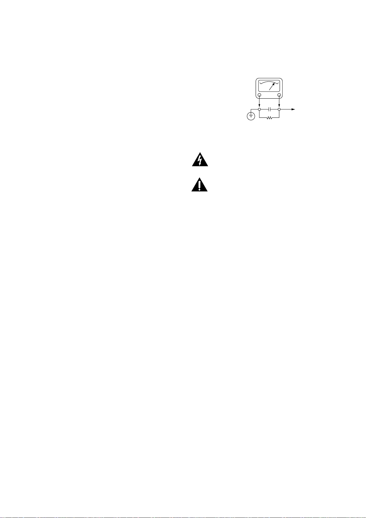
7. AFTER RE-ASSEMBLY OF THE SET ALWAYS PERFORM AN
A.C.LEAKAGE TEST ON ALL EXPOSED METALLIC PARTS OF
THE CABINET, (THE CHANNEL SELECTOR KNOB, ANTENNA
TERMINALS. HANDLE AND SCREWS) TO BE SURE THE SET
IS SAFETY TO OPERATE WITHOUT DANGER OF
ELECTRICAL SHOCK. DO NOT USE A LINE ISOLATION
TRANSFORMER DURING THIS TEST USE AN A.C.
VOLTMETER, HAVING 5000 OHMS PER VOLT OR MORE
SENSITIVITY, IN THE FOLLOWING MANNER; CONNECT A
1500 OHM 10 WATT RESISTOR, PARALLELED BY A .15 MFD,
150.V A.C TYPE CAPACITOR BETWEEN A KNOWN GOOD
EARTH GROUND (WATER PIPE, CONDUIT, ETC.) AND THE
EXPOSED METALLIC PARTS, ONE AT A TIME.
MEASURE THE A.C. VOLTAGE ACROSS THE COMBINATION
OF 1500 OHM RESISTOR AND .15 MFD CAPACITOR.
REVERSE THE A.C. PLUG AND REPEAT A.C. VOLTAGE
MEASUREMENTS FOR EACH EXPOSED METALLIC PART.
VOLTAGE MEASURE MUST NOT EXCEED 75 VOLTS R.M.S.
THIS CORRESPONDS TO 0.5 MILLIAMP A.C ANY VALUE
EXCEEDING THIS LIMIT CONSTITUTES A POTENTIAL
SHOCK HAZARD AND MUST BE CORRECTED IMMEDIATELY.
SUBJECT : GRAPHIC SYMBOLS
SUBJECT : TIPS ON PROPER INSTALLA TION
1. NEVER INSTALL ANY PRODUCT IN A CLOSED-IN RECESS,
CUBBYHOLE OR CLOSELY FITTING SHELF SPACE. OVER
OR CLOSE TO HEAT DUCT, OR IN THE PATH OF HEATED
AIR FLOW.
2. AVOID CONDITIONS OF HIGH HUMIDITY SUCH AS:
OUTDOOR PATIO INSTALLATIONS WHERE DEW IS A
FACTOR, NEAR STEAM RADIATORS WHERE STEAM
LEAKAGE IS A FACTOR, ETC.
3. AVOID PLACEMENT WHERE DRAPERIES MAY OBSTRUCT
REAR VENTING. THE CUSTOMER SHOULD ALSO AVOID THE
USE OF DECORATIVE SCARVES OR OTHER COVERINGS
WHICH MIGHT OBSTRUCT VENTILATION.
4. WALL AND SHELF MOUNTED INSTALLATIONS USING A
COMMERCAL MOUNTING KIT MUST FOLLOW THE FACTORY
APPROVED MOUNTING INSTRUCTIONS A PRODUCT
MOUNTED TO A SHELF OR PLATFORM MUST RETAIN ITS
ORIGINAL FEET (OR THE EQUIVALENT THICKNESS IN
SPACERS) TO PROVIDE ADEQUATE AIR FLOW ACROSS
THE BOTTOM, BOLTS OR SCREWS USED FOR FASTENERS
MUST NOT TOUCH ANY PARTS OR WIRING. PERFORM
LEAKAGE TEST ON CUSTOMIZED INSTALLATIONS.
5. CAUTION CUSTOMERS AGAINST THE MOUNTING OF A
PRODUCT ON SLOPING SHELF OR A TILTED POSITION,
UNLESS THE PRODUCT IS PROPERLY SECURED.
6. A PRODUCT ON A ROLL-ABOUT CART SHOULD BE STABLE
ON ITS MOUNTING TO THE CART. CAUTION THE
CUSTOMER ON THE HAZARDS OF TRYING TO ROLL A CART
WITH SMALL CASTERS ACROSS THRESHOLDS OR DEEP
PILE CARPETS.
7. CAUTION CUSTOMERS AGAINST THE USE OF A CART OR
STAND WHICH HAS NOT BEEN LISTED BY UNDERWRITERS
LABORATORIES, INC. FOR USE WITH THEIR SPECIFIC
MODEL OF TELEVISION RECEIVER OR GENERICALLY
APPROVED FOR USE WITH T.V.’S OF THE SAME OR
LARGER SCREEN SIZE.
8. CAUTION CUSTOMERS AGAINST THE USE OF EXTENSION
CORDS, EXPLAIN THAT A FOREST OF EXTENSIONS
SPROUTING FROM A SINGLE OUTLET CAN LEAD TO
DISASTROUS CONSEQUENCES TO HOME AND FAMILY.
THE LIGHTNING FLASH WITH ARROWHEAD SYMBOL, WITHIN AN
EQUILATERAL TRIANGLE, IS INTENDED TO ALERT THE USER TO THE
PRESENCE OF UNINSULATED “DANGEROUS VOLTAGE” WITHIN THE
PRODUCT’S ENCLOSURE THAT MAY BE OF SUFFICIENT MAGNITUDE TO
CONSTITUTE A RISK OF ELECTRIC SHOCK.
THE EXCLAMATION POINT WITHIN AN EQUILATERAL TRIANGLE IS
INTENDED TO ALERT THE USER TO THE PRESENCE OF IMPORTANT
OPERATING AND MAINTENANCE (SERVICING) INSTRUCTIONS IN THE
LITERATURE ACCOMPANYING THE APPLIANCE.
A.C. V OLTMETER
PLACE THIS PROBE
ON EACH EXPOSED
METAL PART
GOOD EARTH GROUND
SUCH AS THE WATER
PIPE. CONDUIT. ETC
10 WATT
1500 OHM
0.15uF
Page 5

1-4
SERVICING PRECAUTIONS
CAUTION : Before servicing the DVD player covered by this service
data and its supplements and addends, read and follow the SAFETY
PRECAUTIONS. NOTE : if unforeseen circumstances create conflict
between the following servicing precautions and any of the safety
precautions in this publication, always follow the safety precautions.
Remember Safety First:
General Servicing Precautions
1. Always unplug the DVD player's AC power cord from the AC
power source before:
(1) Removing or reinstalling any component, circuit board,
module, or any other assembly.
(2) Disconnecting or reconnecting any internal electrical plug or
other electrical connection.
(3)Connecting a test substitute in parallel with an electrolytic
capacitor.
Caution : A wrong part substitution or incorrect polarity installation
of electrolytic capacitors may result in an explosion hazard.
2. Do not spray chemicals on or near this DVD player or any of its
assemblies.
3. Unless specified otherwise in this service data, clean electrical
contacts by applying an appropriate contact cleaning solution to
the contacts with a pipe cleaner, cottontipped swab, or
comparable soft applicator.
Unless specified otherwise in this service data, lubrication of
contacts is not required.
4. Do not defeat any plug/socket B+ voltage interlocks with which
instruments covered by this service manual might be equipped.
5. Do not apply AC power to this DVD player and/or any of its
electrical assemblies unless all solid-state device heat sinks are
correctly installed.
6. Always connect test instrument ground lead to the appropriate
ground before connecting the test instrument positive lead. Always
remove the test instrument ground lead last.
Insulation Checking Procedure
Disconnect the attachment plug from the AC outlet and turn the
power on. Connect an insulation resistance meter(500V) to the
blades of the attachment plug. The insulation resistance between
each blade of the attachment plug and accessible conductive parts
(Note 1) should be more than 1M-ohm.
Note 1 : Accessible Conductive Parts including Metal panels, Input
terminals, Earphone jacks, etc.
Electrostatically Sensitive (ES) Devices
Some semiconductor (solid state) devices can be damaged easily by
static electricity. Such components commonly are called
Electrostatically Sensitive (ES) Devices. Examples of typical Es
devices are integrated circuits and some field effect transistors and
semiconductor chip components.
The following techniques should be used to help reduce the
incidence of component damage caused by static electricity.
1. Immediately before handling any semiconductor component or
semiconductor-equipped assembly, drain off any electrostatic
charge on your body by touching a known earth ground.
Alternatively, obtain and wear a commercially available
discharging wrist strap device, which should be removed for
potential shock reasons prior to applying power to the unit under
test.
2. After removing an electrical assembly equipped with ES devices,
place the assembly on a conductive surface such as aluminum
foil, to prevent electrostatic charge buildup or exposure of the
assembly.
3. Use only a grounded-tip soldering iron to solder or unsolder ES
devices.
4. Use only an antistatic solder removal device. Some solder
removal devices not classified a “anti-static” can generate
electrical charges sufficient to damage ES devices.
5. Do not use freonpropelled chemicals. These can generate
electrical charge sufficient to damage ES devices.
6. Do not remove a replacement ES device from its protective
package until immediately before you are ready to install it. (Most
replacement ES devices are packaged with leads electrically
shorted together by conductive foam, aluminum foil, or
comparable conductive material).
7. lmmediately before removing the protective material from the
leads of a replacement ES device, touch the protective material to
the chassis or circuit assembly into which the device will be
installed.
Caution : Be sure no power is applied to the chassis or circuit, and
observe all other safety precautions.
8. Minimize bodily motions when handing unpackaged replacement
ES devices. (Normally harmless motion such as the brushing
together of your clothes fabric or the lifting of your foot from a
carpeted floor can generate static electricity sufficient to damage
an ES device.)
Page 6
1-5
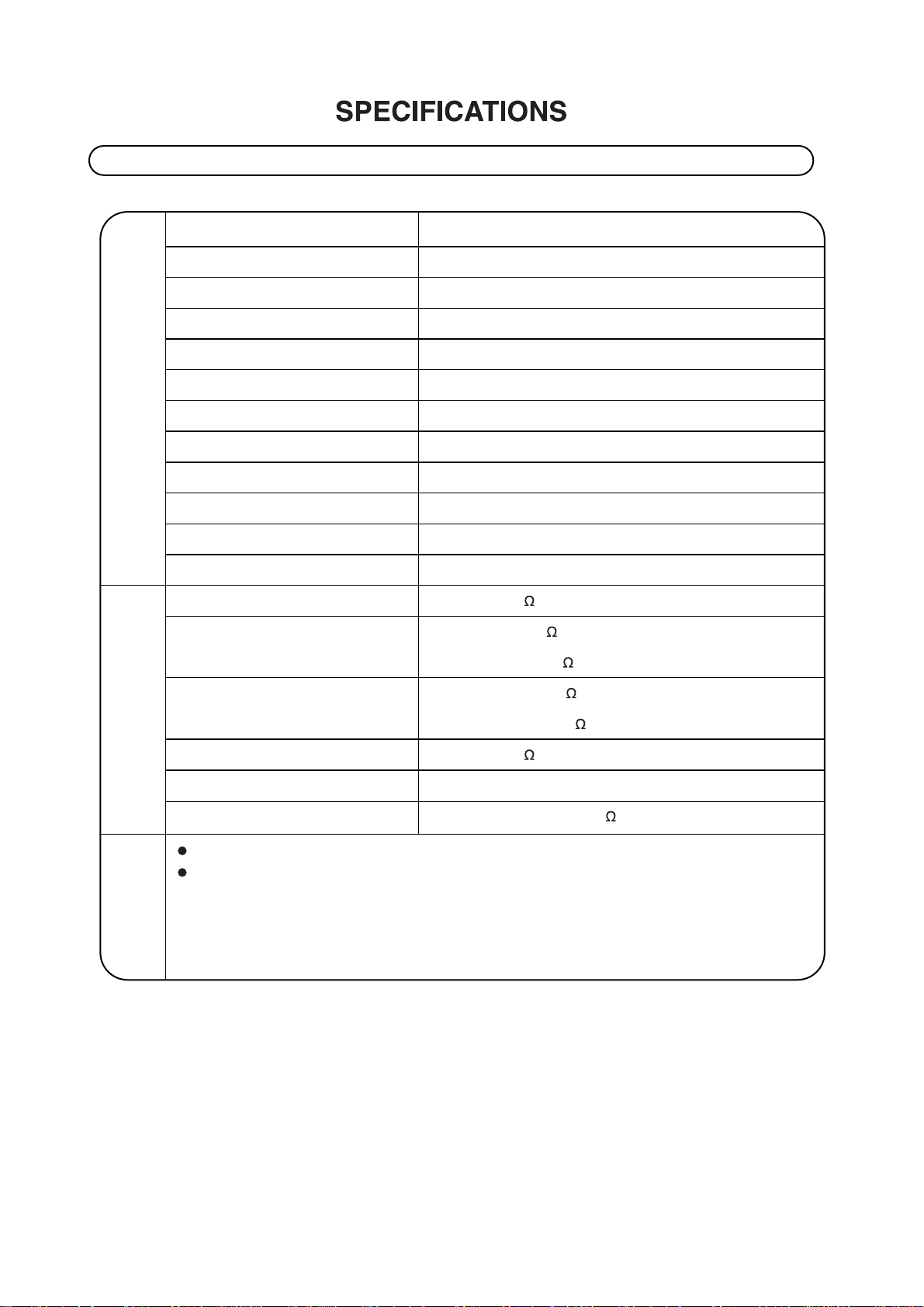
DVD player/Outputs/Supplied Accessories
[DVD player]
[Outputs]
[Supplied
Accessories]
Power supply AC 230V / 50 Hz (EUROPE), AC 110V/60Hz (USA / CANADA)
Power consumption 15 W
Mass 3.3 kg
External dimensions (W X H X D) 285 x 103x 291 mm
Signal system PAL (EUR) , NTSC (USA / CANADA)
Laser Semiconductor laser, wavelength 650 nm
Frequency range (audio) 4 Hz to 20 kHz
Signal-to-noise ratio (audio) More than 100 dB (EIAJ)
Dynamic range (audio) More than 95 dB (EIAJ)
Harmonic distortion (audio) 0.008 %
Wow and flutter
Below measurable level (less than + 0.001 % (W.PEAK)) (EIAJ)
Operating conditions Temperature: 41°F to 95°F, Operation status: Horizontal
Video output 1.0 V (p-p), 75 , negative sync., RCA jack x 1
S-video output (Y) 1.0 V (p-p), 75 , negative sync., Mini DIN 4-pin x 1
(C) 0.286 V (p-p), 75 ,
SCART video output CVBS 1.0 V (p-p), 75 , negative sync., RCA jack x 1
(RGB) 0.63 V (p-p), 75
Audio output (digital audio) 0.5 V (p-p), 75 , RCA jack x 1
Audio output (optical audio) Optical connector x 1
Audio output (analog audio) 2.0 Vrms(1 KHz, 0 dB), 330 , RCA jack (L, R) x 1
Video cable. . . . . . . . . . . . . . . . . . . . . . . . . . . . . . . 1
Audio cable. . . . . . . . . . . . . . . . . . . . . . . . . . . . . . . 1
* Designs and specifications are subject to change without notice.
Page 7
1-6
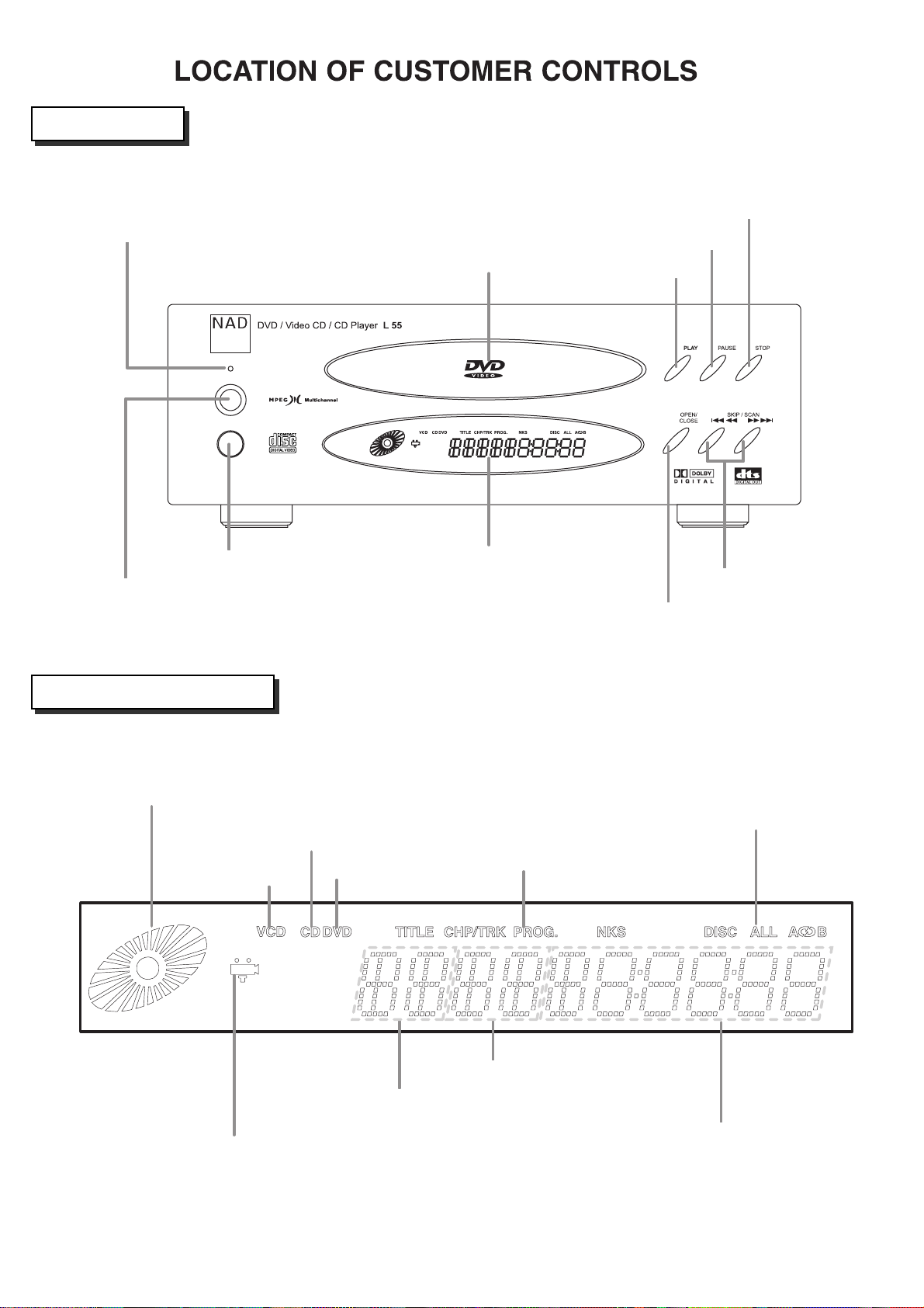
Front Panel
Display Window
POWER indicator
(Standby mode: Blue color)
POWER button
REMOTE SENSOR
DISPLAY WINDOW
OPEN/CLOSE button
SKIP/SCAN buttons
Disc tray
PLAY button
PAUSE/STEP button
STOP button
OPERATING STATUS indicator
CD indicator
VCD indicator
DVD indicator
PROGRAM indicator
Repeat playback
mode indicators
CHP/TRK NUMBER indicator
TOTAL PLAYING
TIME/ELAPSED TIME
indicator
TITLE NUMBER indicator
ANGLE ICON indicator
Page 8
1-7
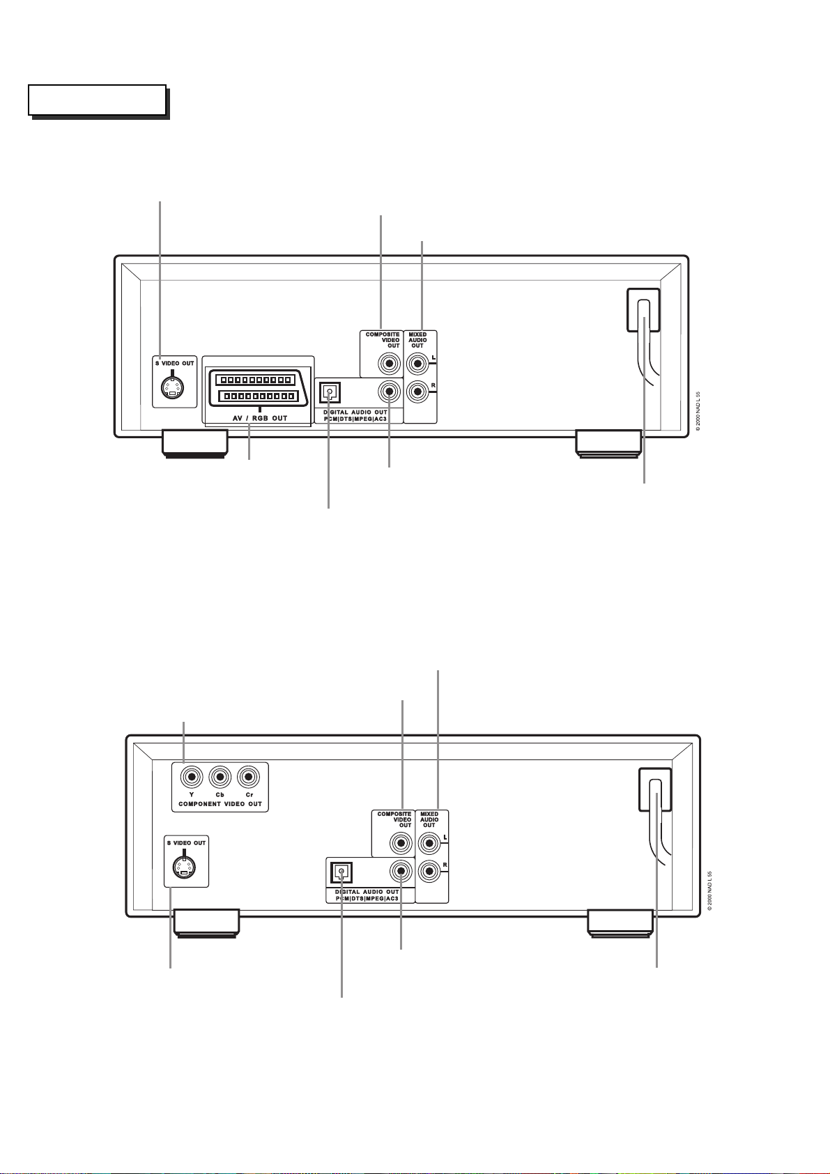
Rear Panel
COMPOSITE VIDEO OUT jack
COMPOSITE VIDEO OUT jack
COMPONENT VIDEO OUT jack
MIXED AUDIO OUT jacks
MIXED AUDIO OUT jacks
EURO AV-TV-VCR OUT jack
OPTICAL DIGITAL AUDIO OUT jack
DIGITAL AUDIO OUT jacks
(COAXIAL)
DIGITAL AUDIO OUT jacks
(COAXIAL)
POWER CORD
Connect to an AC 230V, 50Hz
outlet only.
POWER CORD
Connect to an AC 110V, 60Hz
outlet only.
S-VIDEO OUT jack
S-VIDEO OUT jack
*EUR VERSION
*USA/CANADA VERSION
OPTICAL DIGITAL AUDIO OUT jack
Page 9
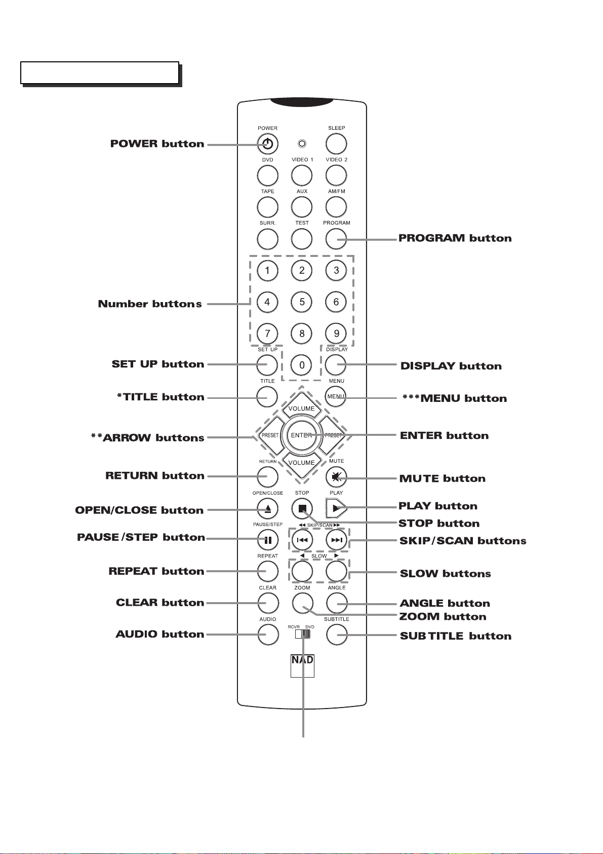
REMOTE CONTROL
****REMOTE SELECT
1-8
Page 10
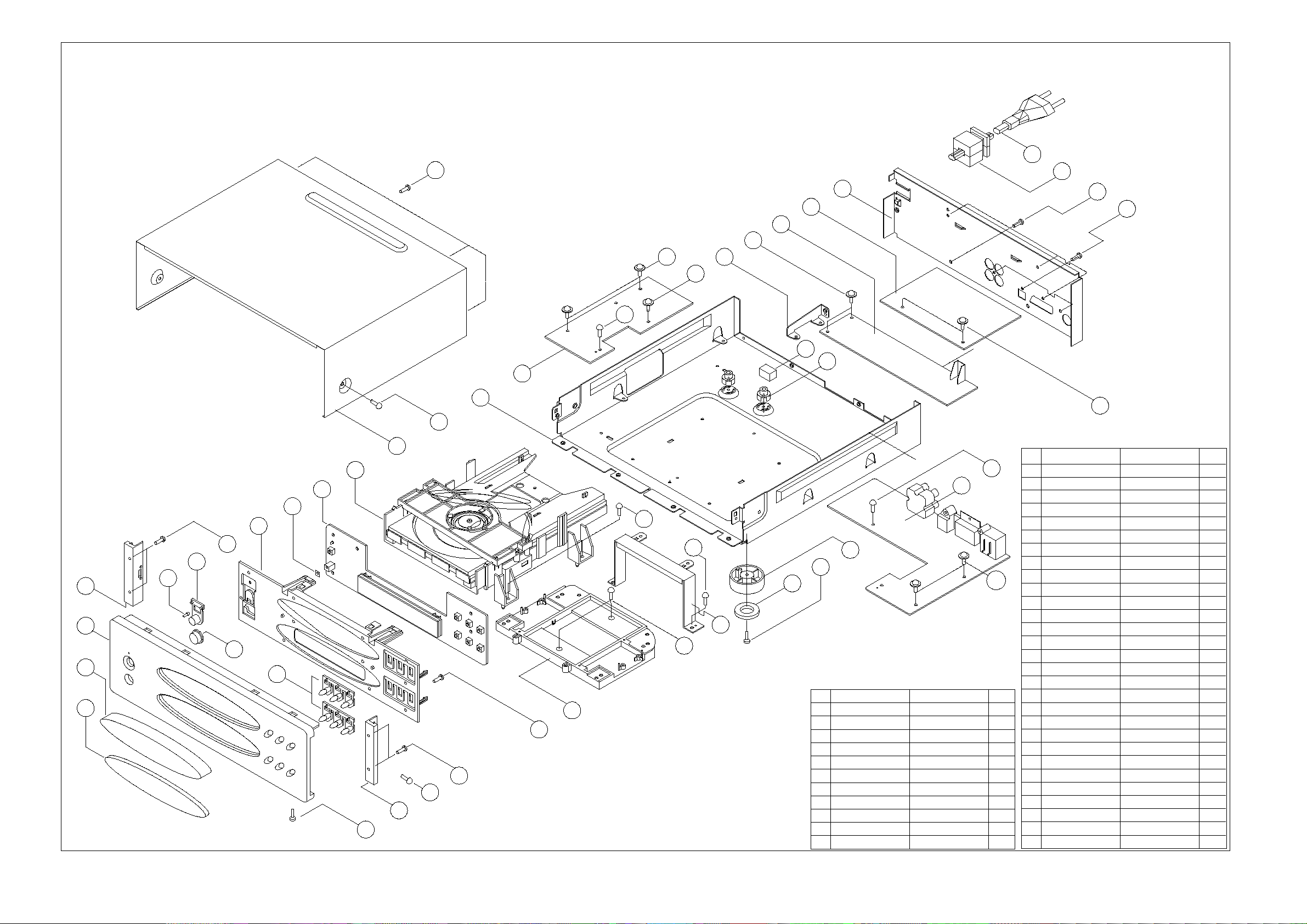
EXPLODED VIEW
S10
26
x4
16
24
25
S10
x5
S9
x3
23
S6
X2
S6
X2
22
S7
S5
18
17
X2
21
S11
11
X2
S6
x2
27
NO
15
10
S7
19
28
S5
9
S2
x2
7
4
5
1
6
2
3
8
14
S1
x11
S2
x2
S4
4
S3
x4
x4
S5
x2
13
x4
S6
12
x4
x4
20
S4
x2
NO
DESCRIPTION
S1
SCREW
S2
SCREW,SPECIAL
SCREW
S3
SCREW
S4
S5
SCREW
S6
SCREW
SCREW
S7
S8
SCREW
SCREW
S9
SCREW
S10
SCREW
S11
PARTS-NO
KTB3+6F
KHD1A016
KTS3+8J
KTB3+6J
KTB3+10G
KTW3+8J 12
KTW3+12J
KTB3+8J
KTB3+10GFZ
KTB3+6JFZ
S6
x2
QT`Y
9
4
4
4
6
2
2
3
9
2KTB4+6JFZ
DESCRIPTION
1
FRONT PANEL
DOOR ORNAMENT
2
3
FIP WINDOW
SIDE BAR
4
LED INDICATOR
5
6
SENSOR WINDOW
POWER KNOB
7
8
DISPLAY KNOB
9
SUB PANEL
10
FRONT PCB ASS'Y
11
BOTTOM CHASSIS
FOOT
12
13
FOOT CUSHION
MECHA. SUPPORT
14
MECHANISM,DVD
15
16
REAR PANEL
17
PCB HOLDER
18
CUSHION
19
AV PCB ASS'Y
20
PCB BRACKET
21
POWER PCB ASS'Y
22
PCB BRACKET
23
JACK,BOARD
24
MAIN PCB ASS'Y
AC CORD BUSHING
25
26
AC CORD
27
TOP CABINET
SHEET
28
29
PARTS-NO
KKM1A106ZC26
KGR1A214M7ZK102
KGU1A244A8
KKM1A051C26
KGL1A188
KGU1A245A10
KBT1A746M7K102
KBT1A745M7K102
KGW1A298
KUP11408C
KUA1A189
BKL1A060
BHG1A171
KMH1A113
BJDTVM502/1
KKF1A210Z
KHE170
KHG1A104
KUP11390Z
KMD1A413
KOP11401CSMPS
KMD1A420
KOP11408B
BVNTFCEIE311A
KHR1A028
BJA2B043Z
KKC3B076S33
KGX1A304
QT`Y
1
1
1
2
0.17
1
1
2
1
1
1
4
4
1
1
1
2
1
1
1
1
1
1
1
1
1
1
1
1-9 1-10
Page 11
2-1
SECTION 2
ELECTRICAL
CONTENTS
ELECTRICAL TROUBLESHOOTING GUIDE......................................................................2-2
1. Power (SMPS) Circuit ..............................................................................................................2-2
............................................................................................................................2-3
3. MPEG Circuit............................................................................................................................2-6
4. Front Circuit (Digitron & Key) ...............................................................................................2-7
5. RF/Servo Circuit ......................................................................................................................2-8
BLOCK DIAGRAMS..................................................................................................................2-12
1. Overall Block Diagram..........................................................................................................2-12
2. Power (SMPS) Block Diagram..............................................................................................2-13
3. RF/CD DSP/DVD DSP/DVD servo Block Diagram ..............................................................2-14
4. Audio Block Diagram............................................................................................................2-15
5. MPEG Block Diagram...........................................................................................................2-16
...........................................................................................................2-17
CIRCUIT DIAGRAMS................................................................................................................2-18
1. Power (SMPS) Circuit Diagram ............................................................................................2-18
2. DVD DSP Circuit Diagram.....................................................................................................2-20
3. Drive & RF Circuit Diagram ..................................................................................................2-22
4. MPEG Circuit Diagram ..........................................................................................................2-24
4-1. WAVEFORMS...................................................................................................................2-26
5. Audio DM & 5.1CH Circuit Diagram.....................................................................................2-28
....................................................................................................................2-30
7. DIGITRON & Key Circuit Diagram........................................................................................2-32
8. Jack Circuit Diagram.............................................................................................................2-34
PRINTED CIRCUIT DIAGRAMS............................................................................................2-36
1. MAIN P.C.BOARD...................................................................................................................2-36
2. POWER P.C.BOARD..............................................................................................................2-38
3. AV P.C.BOARD.......................................................................................................................2-40
4. FRONT P.C.BOARD
...............................................................................................................
2-42
Page 12
2-2
ELECTRICAL TROUBLESHOOTING GUIDE
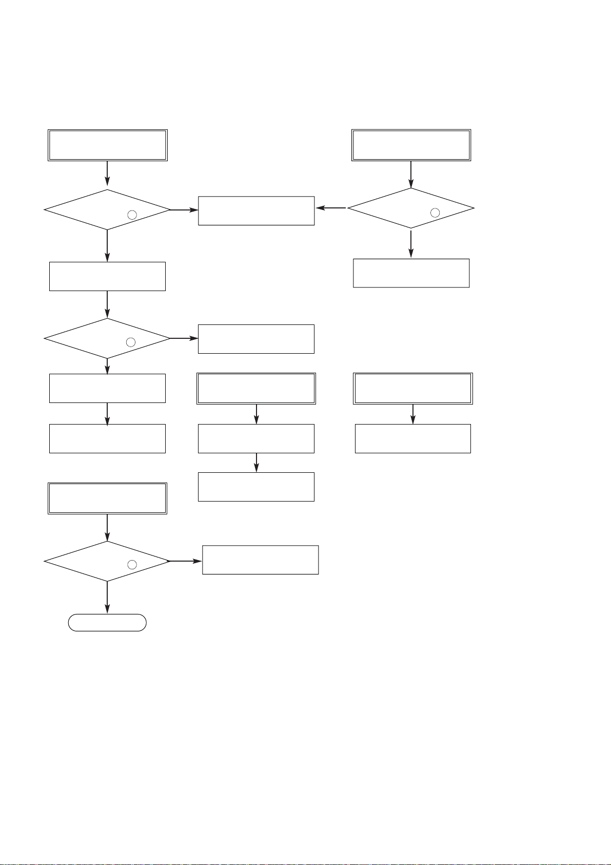
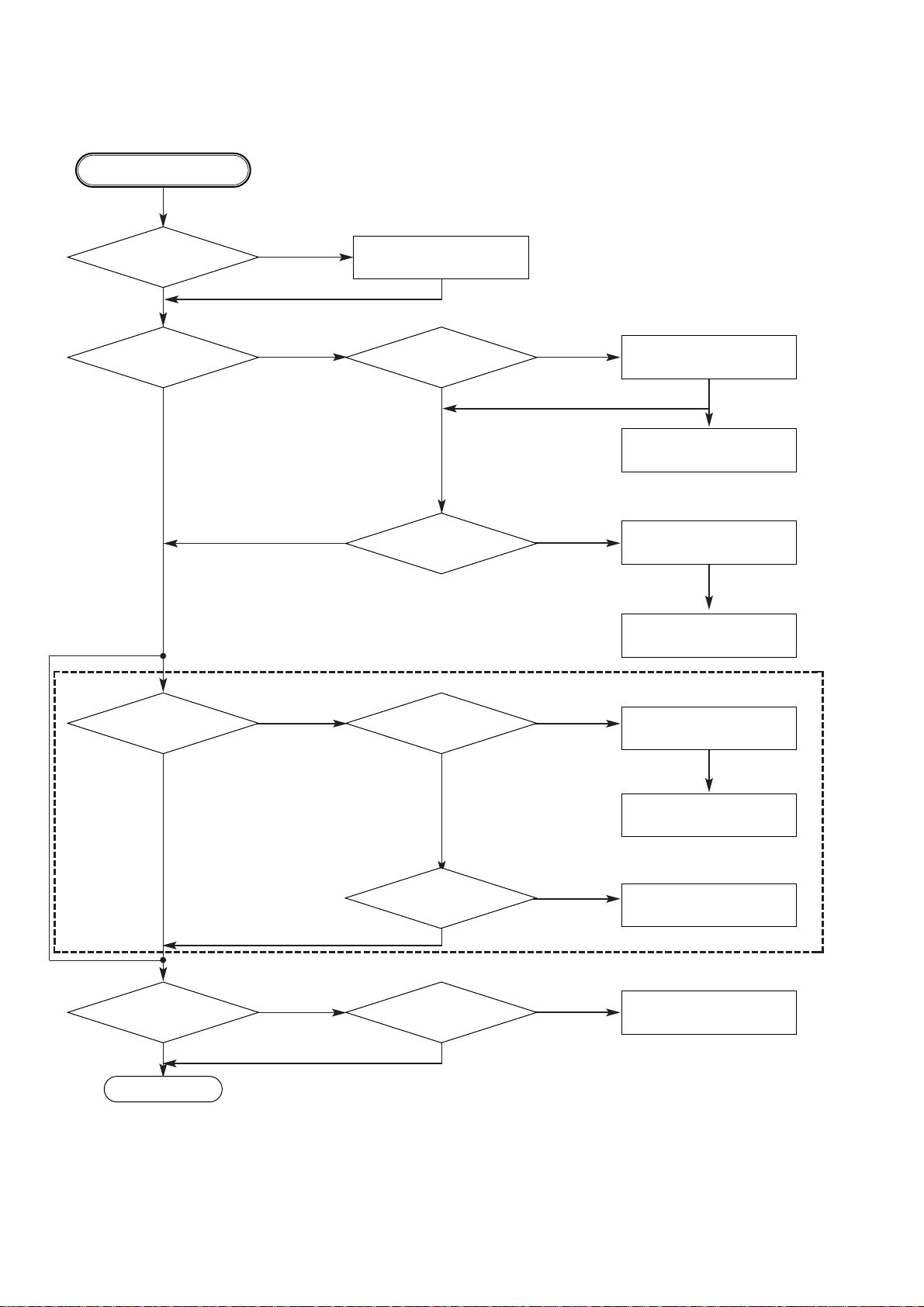
1. POWER (SMPS) Circuit
No LED
Is 5.2V applied
to CN62 Pin 5 ?
NO
Check R622, R623
Is 5.2V applied
to PT61 Pin 1 ?
NO
Check D601-D604
Check Q626, D609
YES
YES
Check FRONT Circuit
Check L620, R620
No 8V No 3.3V
Check Q622, Q623, R632
NO
No 5V_D, 5V_A
Is High State applied
to CN63 Pin 2 ?
YES
Check Q620, Q625, R625
Check IC67, R609
NO FLD
Is -24V applied
to CN62 Pin 3 ?
YES
END
NO
Check D625, IC62
Check IC64, D628, D621
Page 13
2-3
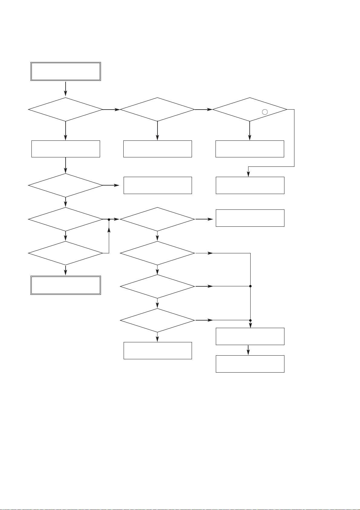
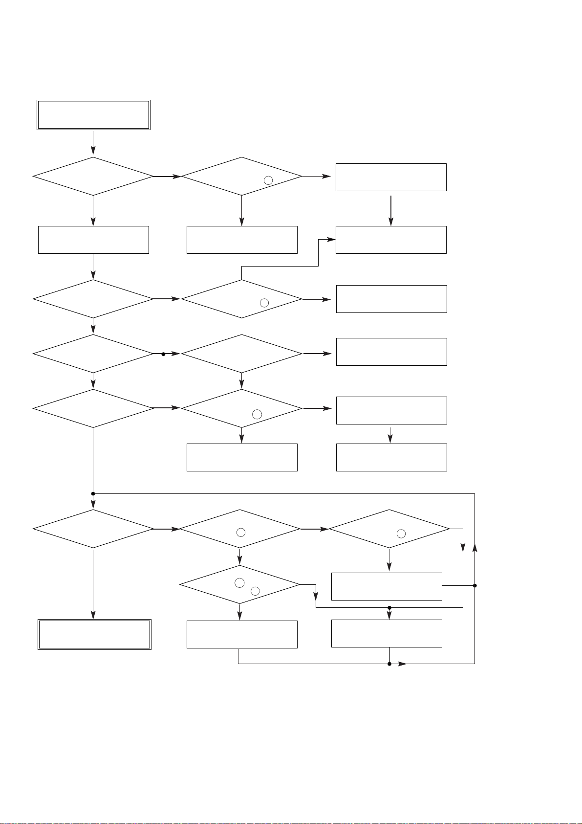
2. u-COM Circuit
A. NO Power
AC In
Is LED On?
YES
Power On Reconnect CN61
Is LED Off ?
YES
Does bar appear
on FLD ?
YES
Does logo appear
on the screen?
YES
NO
NO
NO
Is CN61 conneted
correctly?
NO
Check L620, R620 Check Power Circuit
Is oscillation of
X501 normal?
Are IC503 Pin 14, 28
and 29 normal?
YES
YES
YES
NO
NO
Is 5.2V applied
to CN61 Pin 12 ?
YES
Check FRONT Circuit
Check the oscillation
NO
OK
The waveform on
A[00:21] and D[00:15] of
IC501 normal?
YES
Are IC506 Pin 7, 8
normal?
YES
Replace Main B/D
NO
NO
Check short
YES
Replace IC501 or IC503
Page 14
2-4
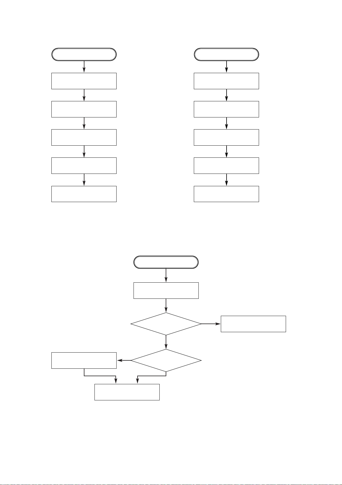
B. Audio abnormal
D. Open/Close abnormal
Check the
connection of P5901.
Check IC501 Pins 13, 14.
Check Audio jack.
YES (If OK)
YES
NO
NO
YES
YES (If OK)
YES
YES (If OK)
YES (If OK)
YES (If OK)
Check PLL FC of MPEG part.
Refer to Audio part.
Refer to MPEG part.
Replace B/D.
Check Front.
Reconnect it.
Refer to SERVO part.
Check the connection of MD.
AUDIO ABNORMAL
OPEN/CLOSE ABNORMAL
C. Video abnormal
Check Video jack.
YES (If OK)
YES (If OK)
YES (If OK)
YES (If OK)
Refer to Video part.
Refer to Encoder part.
Refer to MPEG part.
Replace B/D.
VIDEO ABNORMAL
Page 15
2-5
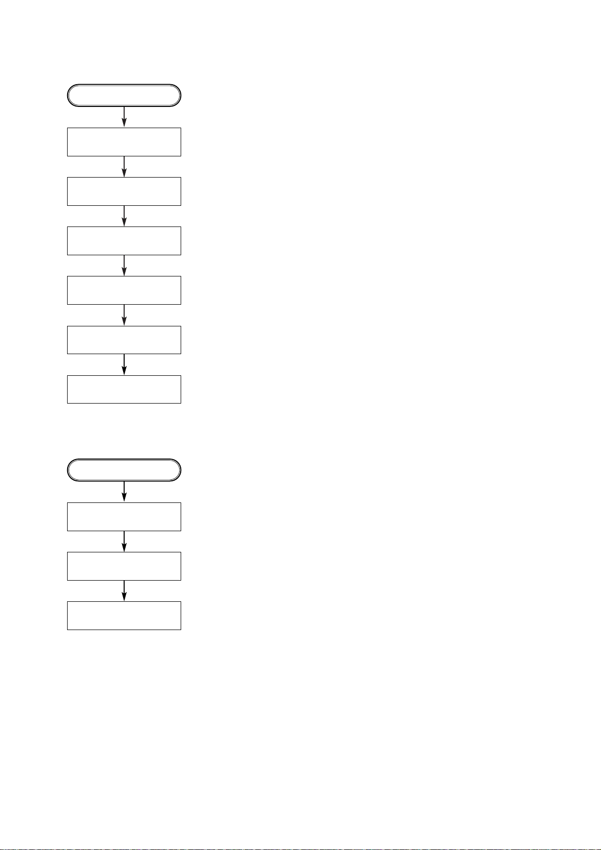
E. Picture abnormal
Check the disc.
If OK
YES (If OK)
YES (If OK)
Refer to Servo part
Check PLL IC of MPEG part
Check DSP
Check MPEG
YES (If OK)
Replace B/D
PICTURE ABNORMAL
F. Disc Error
Check Disc
YES (If OK)
YES (If OK)
Refer to Servo part
Replace B/D
DISC ERROR
Page 16
2-6
Power is on
Does LG Logo appear
on the screen?
Does the
moving picture of the DVD Disc
play on the screen
normally?
Is MPEG data signal normal?
Is error signal normal?
Is MPEG data signal normal?
Is Clock normal?
Does the audio
sound output from MPEG
decoder?
Does the
moving picture of the video
CD play on the screen
normally?
Does the audio sound
output normally?
END
Check power & clock.
Check CD/DVD DSP output
signal.
Check MPEG Decoder input
signal.
Check CD/DVD DSP output
signal.
Check MPEG Decoder input
signal.
Check CD/DVD DSP output
signal.
Check MPEG Decoder input
signal.
Check clock signal
Check clock signal
YES
YES
YES
YES
YES
YES
YES
YES
YES
YES
NO
NO
NO
OK
OK
OK
OK
NO
NO
NO
NO
NO
3. MPEG Circuit
OPTION
If included VCD function.
Page 17
2-7
4. Front Circuit (Digitron & Key)
START
Is LED On?
YES
Power On Check Power Circuit.
Is LED Off ?
YES
Does bar appear
on FLD ?
YES
Does all the buttons
work normally?
NO
NO NO
NO
NO
Is 5.2V applied
to CN61 Pin 12 ?
Is HIGH State appear
on IC91 Pin 2 ?
Does "Main Error"
appear on FLD?
Check waveform of
IC91 Pin 14
Check R904, 906, 909, 910,
R911, 916, 919, 924
NO
YES
YES
YES
YES
NO
NO
Check L901
Check Q901, Q904, D902
Check the oscillation of X901
and Replace IC91 or X901
Check Power Circuit
Check S902-S907, S909
Check Solder
YES
Does remote control
work normally?
YES
NO NO
Does waveform of
IC92 Pin 1 appear?
YES YES
Is IC91 Pin 24 connected
to IC92 Pin 1 ?
YES
Replace IC91OK
NO
Is 5V applied to
IC92 Pin 3 ?
Replace IC92
Check Solder
NO
Page 18

2-8
Does signal pulse
input to IC201 Pins 58, 59 when
the powe is on?
Does signal goes
"High" to IC201 Pin194 when the
power is on?
Does
TTL pulse output to
IC201 Pins 140, 142?
Does
33.8688MHz clock input
to IC201 Pin 63?
Is IC201
Pins 83, 84, 88, 89 voltage
about 2.2V?
Replace IC201
(IC206 soldering or IC defect).
Check power circuit.
Check "2.µ-COM Part".
Replace X301 or IC304
(30MHz clock defect)
CHECK POINT(General)
5. RF/Servo Circuit
A.
END
NO
NO
NO NO
NO
YES
YES
YESYES
YES
Page 19

2-9
Does tray open or close?
Does the pick-up
slide inner or outer
track?
Fig.1. SLED Driver waveform
Fig.2. Focus Driver waveform
Does
the voltage change
at PMD04 Pins 1, 2 more than
2V on the basis of
3.8V?
Pressing
the open/close key
repeatedly, check the voltage of IC2M1
Pins 13, 14 change
0V to 5V
Does
PMD03 Pin 7 change
high to low?
Does
the pick-up lens move up
and down?
Check Focus Driver output.
(IC201 Pin 83, IC2M1 Pins 37, 38)
Check SLED Driver output.
IC201 Pin 88 IC2M1 Pins 28, 29.
IC201 Pin 88 no output : IC201 is defective
IC2M1 Pin 18 no output : IC2M1 is defective
IC201 Pin 83 no output : IC201 is defective
IC2M1 Pins 1, 2 no output : IC2M1 is defective
DECK assembly is defective.
Slide the pick-up to
inner track.
.Power on
Check loading Part.
Push Pick-up to inner track to
the end by hand.
DECK assembly is defective.
(Limit sw)
check µ-COM Part.
Replace IC2M1.
No disc
B.
END
NO
NO
NO
NO
NO
NO
YES
YES
YES
YES
YES
YES
Page 20

2-10
FOCUS ON?
Check
the focus error moving the
lens up and down.
(IC2A1 Pin 42)
Does the
TTL level change at IC201
Pin 78 and 132 moving
the lens?
Does the disc turn?
IC201 Pin169 is "High"?
Is OK the track jump.
Does the signal
pulse appear at IC2A1 Pins
39, 29?
Does the screen appear?
OPEN/CLOSE
Replace µ-COM or IC201.
Replace IC201.
Check IC2A1 Pin 11,12,13,14
in DVD Mode
Fig.3. FOCUS ERROR waveform
IC201 no output : Pick-up is defective.
Check IC201 and IC2M1 when PMD03 Pin 6 is abnormal
Check IC2M1 Pin 21, PMD03
Pin 6 turn when the IC2M1
Pin 21 is less than 2.2V.
Check A
Video Part is defective.
Check "5.MPEG Circuit."
Check "7.OSD/Video Circuit."
Replace µ-COM part.
IC2A1 is defective.
DISC IN
C.
END
NO
NO
NO
NO NO
NO
NO
NO
YES
YES
YES
YES
YES
YES YES
YES
Page 21

2-11
Is the eye-pattern vivid?
Does the
sawtooth waveform emit
at IC2A1 Pin 41?
Does the 1.6V emit?
Check RF Eye-Pattern.
RF : 1.5-1.6V(IC2A1 Pin 57)
Fig.5. RF
waveform
Check IC2A1 Pins 5, 6, 7, 8.
No signal: Pick-up is defective
Replace IC201.
Check IC201 Pin84.
No signal at IC201 : IC201 is defective
• Check IC201 Pin 162.
• Check the clock at the IC201 Pins 28, 30.
• Both are normal : IC201 is defective
Replace IC2A1.
CHECK A
D.
END
NO
NO NO NO
YES
YES YES YES
Page 22

2-12
BLOCK DIAGRAM
Page 23

2-13
2. Power(SMPS) Block Diagram
RECTIFIER(FLD)
RECTIFIER LINE FILTER
SWITCHING TR
RECTIFIER(14V) LPF
REG(8V)
REG(3.3V)
REG(3.3V)
PWR ON/OFF
F+
F-
-24VA
12VA
8V
5.2VA
5V_D
5V_A
3.3V
3.3V_M
2.5V
LPF
RECTIFIER(9V)
RECTIFIER(5.2V)
TRANS
LPF
FEED B.
Page 24

2-14
IC2A1
33P3721
RF Signal
Processor
IC206
DVDSP-3301
CD/DVD DSP
DVD SERVO
DRAM
256K x 16bit
IC2M1
KA3032
SpindleMotor,LoadingMotor,
Actuator Driver
PICK
UP
DVD:A,B,C,D,
FE,TE,PI,SBADD
SENS,FOK,SLD_FG,
MSDATO,DEFECT,DSP_SENSE
SQSO,SQCK,SCOR
XLAT,S_CLK,S_DATA
DSP_CS,/WR,/RD
DO[0:7]
AO[0:5]
DVD_DATA[0:7]
MCK
UCOM
I/F
MPEG
I/F
UCOM
I/F
M/D
DVD/CD RF
MIRR,TZC
ICADDR[0:8]
ICDATA[00:15]
MON,MDP
FDO,TDO,FMO
Spindle
focus,tracking,loading,sled
SPINDLE_FG
Load open/close(loading control)
CD:A,B,C,D/E,F
4
4
5
3
3
3
8
6
8
8
2
4
9
16
3. RF/CD DSP/DVD DSP/DVD SERVO Block Diagram
Page 25

2-15
4. Audio Block Diagram
IC402
LPF &Buffer
NJM4580M
OP AMP
IC401
PCM1716
Audio DAC
IC451
PCM1600
Audio DAC
(5.1CH)
U-COM
I/F
DAC_RST
S_DATA
S_CLK
DAC_L0
DA_LRCK
DA_BCK
DA_XCK
DA_DATA0
DAC_RST
S_DATA
S_CLK
DAC_L1
DA_LRCK
DA_BCK
DA_XCK
DA_DATA[1:3]
MPEG
I/F
U-COM
I/F
MPEG
I/F
IC452
LPF &Buffer
NJM4580M
OP AMP
A/V
JACK
I/F
IC453
LPF &Buffer
NJM4580M
OP AMP
IC454
LPF &Buffer
NJM4580M
OP AMP
L
R
L
R
FL
FR
FL
FR
RL
RR
CENTER
WOOFER
CENTER
WOOFER
RL
RR
Page 26

2-16
5. MPEG Block Diagram
DSP
I/F
IC301
ZiVA-3
MPEG A/V
Decoder
IC303
1M x 16bit
SDRAM
IC302
GM72V1621
1M x 16bit
SDRAM
IC304
GENERATOR
27MHz
X-TAL
U-COM
I/F
DVD_DATA[0:7]
DAI_DATA
DA_DATA[0:3]
DA_BCK,DA_XCK,DA_LRCK
SPDIF
AUDIO
I/F
U-COM
I/F
SERVO
I/F
DA_XCK
MPEG_CLK
8
SDCLK1,ZISENB
REQZ1
2
2
A[00:02]
D[00:07]
MPEG_ERROR
MPEG_RST
DVD_SD_CS0,DVD_UDQM
DVD_MD[0:15]
DVD_MA[0:11]
DVD_SD_CAS
DVD_SD_RAS
DVD_SD_CLK
DVD_MWE
DVD_LDQM
DVD_SD_CS1
S_CLK,S_DATA<DPLL_L
MCK
8
4
4
21216
3
Page 27

2-17
6. -COM Block Diagram
AV JACK
I/F
IC506
XC9536
IC502
FLASH
ROM
FRONT
I/F
IC503
DRAM
IC505
74HC374
IC501
SH6417034
MPEG
I/F
SERVO
I/F
DSP
I/F
IC504
EEPROM
2402/2416
16:9,SYSTEM_SW
LD_ON,LOAD CLOSE,MIRR,ACT_MUTE
LOAD_OPEN,SPINDLE_FG,SLD_FG,
D[00:07],A[00:02],IIC_CLK,IIC_DATA,SCLK0, MPEG_RST
,MPEG_INT,V_MUTE,A_MUTE,DAC_RST,Y_SEL
MPEG_ERROR
,DAC_L0
,RF_LAT
,/DSP_CS
,/MPEG_CS
,/PP_CS 16:,
,Y_SEL
,,MPEG_RST
PWR_CTL
,SENS,LIMIT_SW
,MIC_ON,CLOSE_SW
,OPEN_SW,MPEG_WAIT
,16:9,,MPEG_RST
,M_RESET
M_RESET
,RXD0
,TXD0
,SCK0
,F_REQ
,MODE_SW
,M_REQ,
,ECHO
IIC_CLK
,IIC_DATA
SENS_MCOM
, MICOM_WAIT
/IOCS1,/WR
D[00:04]
A[19:21]
A[01:19]
D[00:15]
A[01:09]
D[00:15]
A[01:21]21 D[00:15]
D[00:07]
DAC_RST
,E_DR
,/S_XRST
,XLAT
,ACT_MUTE
,LOAD_OPEN
,LOAD CLOSE
,/PWR_RST
EXP_W2
,/PWR_CTL
2
2
2
88
8
10
2
2
2
19
16
9
16
16
21
D[00:07],A[00:05], ,E_SIN,E_CLK
LOAD_FR,F/R,LOCK,DEFECT,FOK
DSP_SENSE,
Page 28

CIRCUIT DIAGRAM
1. POWER (SMPS) CIRCUIT DIAGRAM
2-18 2-19
Page 29

2-20 2-21
2. DIAGRAMA DE CIRCUITO DE DVD DSP
5
56
TRACKING LOOP
FOCUS LOOP
SLED LOOP
SPINDLE LOOP
WAVEFORM
IC204 is defective.
Scratched CD Audio abnormal.
IC203 is defective.
AD Converter Error
- No tracking/Focus control
2. DVD DSP CIRCUIT DIAGRAM
Page 30

2-22 2-23
3. DRIVE & RF CIRCUIT DIAGRAM
4
1
1
6
2
3
TRACKING LOOP
FOCUS LOOP
SLED LOOP
SPINDLE LOOP
WAVEFORM
OPEN
OPEN
Q2M3 is defective.
Spindle rotates in high speed.
IC2A2 is defective.
No fucus & tracking control.
Q2A1, Q2A2 are defective.
CD/DVD LD will not be on.
Page 31

2-24 2-25
4. MPEG CIRCUIT DIAGRAM
• NO DVD SCREEN DISPLAY
• NO VCD SCREEN DISPLAY.
• NO CD SOUND OUT.
• NO 2CH AUDIO OUT
• NO 2CH AUDIO OUT
WAVEFORM
IC302, IC303 are defective.
A/V out bad.
X301 is defective.
No power on.
Q302, 303 are defective.
Component Y out defective.
Q301, 304 are defective.
Y/C out is defective.
IC307 is defective.
Component out bad.
Page 32

4-1.
Page 33

2-28 2-29
5. Audio DM & 5.1CH Circuit Diagram
2CH L SIGNAL
2CH R SIGNAL
'00 01.17 R10539B
DVD3351ND'S
Q401 is defective.
2CH Audio out bad.
IC404 is defective.
Audio bad
IC4M1 is defective.
Mic input bad.
IC403, Q404 are defective.
Digital data out bad.
IC402 is defective.
2CH Audio out bad.
IC401 is defective
2CH Audio out bad
Page 34

2-30 2-31
6. µ-com/ Expander
FLASH ROM DRAM
MAIN CPU
E
X
P
A
N
D
E
R
EEPROM
CPLD
OPEN
OPEN
'00 03. 28 R10537B
DVD3351ND'S
Audio output is unstable
Servo will not operate
X501 No Power on
Video output level is unstable
Open, Close Error
Servo will not operate
FLD Error
Page 35

7. DIGITRON & KEY CIRCUIT DIAGRAM
2-32 2-33
Page 36

8. JACK CIRCUIT DIAGRAM
2-34 2-35
Page 37

LOCATION GUIDE
(BOTTOM SIDE)
(TOP SIDE)
Page 38

2. POWER P.C.BOARD
2--38 2-39
Page 39

3. AV P.C.BOARD
2-40 2-41
Page 40

4. FRONT P.C.BOARD
2-42 2-43
Page 41

3-1
Numbering System of Resistor Numbering System of Capacitor
Example Example
KRD
Type25WattageFShapeJTolerance
101
Value
KCKT
Type1HVoltage
101
ValueKTolerance
B
Peculiarity
Resistor Type Wattage Tolerance
KRD: Carbon 20:1/5W F:= ±1%
KRG: Metal Oxide 25:1/4W J:= ±5%
50:1/2W K:= ±10%
1:1W
KRF:Metal Cement 2:2W
KRQ:Fusible 3:3W
Capacitor Type
Voltage
Tolerance
KCEA Type Others
KCB:Ceramic 0J:6.3V 1H:50V DC C: ±0.25pF
KCC:Ceramic 1A:10V 1:125V DC G: ±2%
KCK:Ceramic 1C:16V KC:400V AC J: ±5%
KCQI:Polyester 1E:25V 25 : 250V AC K: ±10%
KCQP:Polypropylene 1H:50V Z: +80%, –20%
KCQS:Polystyrol 1V:35V
KCEA:ELECT 2A:100V
KCFT:Semiconductor
Notes : • Part numbers are indicated for most mechanical parts.
Please use this part number for parts order.
• IMPORTANT SAFETY NOTICE.
Components identified by mark have special characteristics important for safety.
When replacing any of these components, use only manufacturer's specified parts.
• The unit of resistance is OHM(Ω)
K=1000(Ω), M=1000(KΩ)
• The unit of capacitance is MICROFARED(µF)
P=10
-6
µF
RESISTORS AND CAPACITORS
PARTS LIST
HOW TO USE THIS PARTS LIST
1. This Parts List lists those parts which are considered necessary for repairs. Other common parts, such as resistors and
capacitors, are listed in the “Common List for Service Parts” from which these parts should be selected and stocked.
2. Parts not shown in the Parts List and “Common List for Service Parts” will not in principle be supplied.
3. How to read the Parts List.
ATTENTION
1. When placing an order for parts, be sure to list the Part No., Model No, and the description of each part. Otherwise, the
non-delivery of the part or the delivery of a wrong part may result.
2. Please make sure that Part No. is correct when ordering.
If not, a part different from the one you ordered may be delivered.
3. Since the parts shown in Parts List of Preliminary Service Manual may have been the subject of changes, please use this
Parts List for all future reference.
WARNING
( ) INDICATES SAFETY CRITICAL COMPONENTS. FOR CONTINUED SAFETY, REPLACE SAFETY CRITICAL COMPONENTS
ONLY WITH MANUFACTURE’S RECOMMENDED PARTS.
AVERTISSEMENT
( ) IL INDIQUE LES COMPOSANTS CRITIQUES DE SÉCURITÉ. POUR MAINTENIR LE DEGRÉ DE SÉCURITÉDE L’APPAREIL, NE
REMPLACER QUE DES PIÉCES RECOMMANDEES PAR LÉ FABRICANT.
SECTION 3
Page 42

3-2
KOP11408C FRONT PCB ASS'Y DVDL55C
KIP11408C FRONT PCB AUTO ASS'Y
KUP11408Z PCB , FRONT 247*163
C901 KCEA1CKS470T CAP , ELECT 47UF 16V
C902 KCBS1H104ZFT CAP , CERAMIC 0.1UF 50V Z
C903 KCEA1CKS470T CAP , ELECT 47UF 16V
C904 KCEA1CKS100T CAP , ELECT 10UF 16V
C906 KCEA1HKS1R0T CAP , ELECT 1UF 50V
C908 KCBS1H102KBT CAP , CERAMIC 1000PF 50V K
C909 ~ C914 KCEA1CKS101T CAP , ELECT 100UF 16V
C919 , C920 KCBS1H104ZFT CAP , CERAMIC 0.1UF 50V Z
C921 KCEA1HKS1R0T CAP , ELECT 1UF 50V
D902 BVDSEL2E10CFT L.E.D , BLUE
D904 , D912 KVD1N4148MT DIODE 1N4148
D916 KVD1N4003ST DIODE 1N4003
IC91 BVIANAM1318DVD IC , MICOM LC866412A-5S47
L901 KLQ02C100KT COIL , AXIAL 10UH , K
Q901 , Q902 KVTKRC107MT T.R KRC107M
Q904 KVTKRC107MT T.R KRC107M
R901 KRD20TJ221T RES , CARBON 220 OHM 1/5W J
R902 , R904 KRD20TJ103T RES , CARBON 10K OHM 1/5W J
R906 KRD20TJ103T RES , CARBON 10K OHM 1/5W J
R909 KRD20TJ681T RES , CARBON 680 OHM 1/5W J
R910 KRD20TJ821T RES , CARBON 820 OHM 1/5W J
R911 KRD20TJ122T RES , CARBON 1.2K OHM 1/5W J
R912 KRD20TJ103T RES , CARBON 10K OHM 1/5W J
R916 KRD20TJ152T RES , CARBON 1.5K OHM 1/5W J
R919 KRD20TJ222T RES , CARBON 2.2K OHM 1/5W J
R922 KRD20TJ472T RES , CARBON 4.7K OHM 1/5W J
R924 KRD20TJ822T RES , CARBON 8.2K OHM 1/5W J
R925 , R926 KRD20TJ103T RES , CARBON 10K OHM 1/5W J
R927 KRD20TJ473T RES , CARBON 47K OHM 1/5W J
R929 KRD20TJ103T RES , CARBON 10K OHM 1/5W J
R931 KRD20TJ331T RES , CARBON 330 OHM 1/5W J
R936 KRD20TJ473T RES , CARBON 47K OHM 1/5W J
R938 KRD20TJ103T RES , CARBON 10K OHM 1/5W J
R940 KRD20TJ102T RES , CARBON 1K OHM 1/5W J
S902 ~ S907 KST1A012ZT SW , TACT SKHV10910G
S909 KST1A012ZT SW , TACT SKHV10910G
BK93 KMD1A387 BRACKET , PCB
BN68 KWB1D909120LM WIRE ASS'Y
CN61 KJP17GB113ZG WAFER , CARD CABLE"
CN63 , CN64 KJP21GA117ZG WAFER , CARD CABLE (21P 1M/ GF102-21S-TS
CN65 , CN66 KJP30HA129ZP CONNECTOR FLUG, FLOATING
F901 KFLHNV07SM08T FIP DISPLAY HNV-07SM08T
IC92 KRVHIM602H32 SENSOR , REMOCON
PB91 , PB92 KMD1A374 BRACKET , FLT
X901 BVFCST600MGW RESONATOR , CERAMIC CST6.00MGW
KWC1B2A17A150B CARD CABLE
KOP11390E SUB PCB ASS'Y DVD-L55C
KIP11390E SUB PCB AUTO ASS'Y DVD-L55C
KUP11390Z PCB , SUB 197 * 197
C501 , C502 KCEA1CH471T CAP , ELECT 470UF 16V
LOAD No. PART No. DESCRIPTION REMARKS
Page 43

3-3
C503 , C504 KCBS1H101KBT CAP , CERAMIC 100PF 50V K
C512 KCEA1CH470T CAP , ELECT 47UF 16V
C514 KCBS1H100JCT CAP , CERAMIC 10PF 50V J
C516 KCBS1H103ZFT CAP , CERAMIC 0.01UF 50V Z
C518 ~ C522 KCEA1CH471T CAP , ELECT 470UF 16V
C523 KCBS1H100JCT CAP , CERAMIC 10PF 50V J
C524 KCBS1C152MXT CAP , CERAMIC 1500PF 16V M
C525 , C526 KCBS1H681KBT CAP , CERAMIC 680PF 50V K
C527 KCBS1C152MXT CAP , CERAMIC 1500PF 16V M
C528 ~ C530 KCBS1H681KBT CAP , CERAMIC 680PF 50V K
D501 KVDMTZJ5.1BT DIODE , ZENER 5.1V 1/2W
L501 ~ L505 KLQ02C1R8KT COIL 1.8UH , K
L521 ~ L523 KLQ02C1R8KT COIL 1.8UH , K
Q501 KVTKRC107MT T.R KRC107M
Q502 KVTKTA1266YT T.R KTA1266Y
Q503 ~ Q506 KVTKTD1302T T.R KTD1302T
Q507 KVTKTA1266YT T.R KTA1266Y
Q512 KVTKTC3198YT T.R KTC3198Y
Q517 , Q518 KVTKTA1266YT T.R KTA1266Y
R501 KRD20TJ750T RES , CARBON 75 OHM 1/5W J
R502 KRD20TJ470T RES , CARBON 47 OHM 1/5W J
R503 KRD20TJ560T RES , CARBON 56 OHM 1/5W J
R507 , R510 KRD20TJ102T RES , CARBON 1K OHM 1/5W J
R512 , R515 KRD20TJ102T RES , CARBON 1K OHM 1/5W J
R520 KRD20TJ222T RES , CARBON 2.2K OHM 1/5W J
R521 KRD20TJ821T RES , CARBON 820 OHM 1/5W J
R525 KRD20TJ222T RES , CARBON 2.2K OHM 1/5W J
R527 , R528 KRD20TJ560T RES , CARBON 56 OHM 1/5W J
R531 , R532 KRD20TJ101T RES , CARBON 100 OHM 1/5W J
R533 , R534 KRD20TJ221T RES , CARBON 220 OHM 1/5W J
R535 , R536 KRD20TJ104T RES , CARBON 100K OHM 1/5W J
R537 KRD20TJ221T RES , CARBON 220 OHM 1/5W J
R538 KRD20TJ104T RES , CARBON 100K OHM 1/5W J
R539 KRD20TJ102T RES , CARBON 1K OHM 1/5W J
R540 KRD20TJ104T RES , CARBON 100K OHM 1/5W J
R541 KRD20TJ221T RES , CARBON 220 OHM 1/5W J
R542 KRD20TJ102T RES , CARBON 1K OHM 1/5W J
R545 , R546 KRD25TJ681T RES , CARBON 680 OHM 1/4W J
BN52 KWB2B905150GN WIRE ASS'Y
BN62 KWB1D905120LM WIRE ASS'Y
CN51 KJP17GA117ZG WAFER , CARD CABLE
CN53 , CN54 KJP21GA117ZG WAFER , CARD CABLE (21P 1M/ GF102-21S-TS
CN58 KJP08GA117ZG WAFER , CARD 8P 1M/M
CN62 KJP05GA47ZG WAFER GIL-S-5P-S2T2EF
CN68 KJP08GA117ZG WAFER , CARD 8P 1M/M
JK51 BJS9L001Z MODULE , OPTICAL (TX)
JK52 KJJ9M001Z JACK , S-VIDEO (1P/H)
JK53 KJP21GA118ZP SCART CONNECTOR
JK54 KJJ4P037Z JACK , BOARD
JW51 KWE7202120RV WIRE ASS'Y
KOP11394C MAIN PCB ASS'Y (LGE) 6881R-2200B
6870R2090AM PWB(PCB) SDMG311PDM ANAM EPOXY FR-4 2LA
LOAD No. PART No. DESCRIPTION REMARKS
Page 44

3-4
IC501 0IHI641703B IC , HITACHI HD6417034AFI20 112QFP BK MICOM
IC503 0IEB114162A IC , ELITE MEMORY TECH M11B416256A-35J ELITE 4M(256K
X501 6212S-AMLCB RESONATOR CSTCV20.00MXJ040-TC20 MURATA 2
L501 , L506 6200HJC102A FILTER(CIRC) , EMI HB-1M2012-102JT CERATECH TP 3K
R507 , R508 0RH0000C622 RESISTOR , CHIP 0 1/16W 5 D.R/TP
R573 0RH0000C622 RESISTOR , CHIP 0 1/16W 5 D.R/TP
R592 0RH0000D622 RESISTOR , CHIP 0 1/10W 5 D.R/TP
R5A6 , R5A7 0RH0000D622 RESISTOR , CHIP 0 1/10W 5 D.R/TP
R564 0RH1001C622 RESISTOR , METAL 1KOHM 1 / 16 W 1608 5.00% D
R535 ~ R537 0RH1002C622 RESISTOR , CHIP 10K 1/16W 5 D.R/TP
R569 , R583 0RH1201C622 RESISTOR , CHIP 1.2K 1/16W 5 D.R/TP
R584 , R588 0RH1201C622 RESISTOR , CHIP 1.2K 1/16W 5 D.R/TP
R593 0RH1201C622 RESISTOR , CHIP 1.2K 1/16W 5 D.R/TP
R571 0RH4702C622 RESISTOR , CHIP 47K 1/16W 5 D.R/TP
C515 , C517 0CH1225F944 CAPACITOR , FIXED CERA 2UF 16V 80%,-20% Y5V(F) 3216 R
C506 , C507 0CH1104K942 CAPACITOR , CHIP [CERAM 0.1UF 50V Z Y5V(F) 1508 R/TP
C514 0CH1104K942 CAPACITOR , CHIP [CERAM 0.1UF 50V Z Y5V(F) 1508 R/TP
C535 0CH1104K942 CAPACITOR , CHIP [CERAM 0.1UF 50V Z Y5V(F) 1508 R/TP
C523 , C525 0CH4221K412 CAPACITOR , CHIP [CERAM 220P 50V J COG 1.6X0.8 R/TP
C526 , C529 0CH4221K412 CAPACITOR , CHIP [CERAM 220P 50V J COG 1.6X0.8 R/TP
C531 , C532 0CH4221K412 CAPACITOR , CHIP [CERAM 220P 50V J COG 1.6X0.8 R/TP
PMD03 6630R-FB02H CONNECTOR (CIRC) , FFC 04-6232-108-008-800 ELCO 8PIN
IC2A1 0ITI333721A IC , TI
INSTRUMENT SSI33P3721(VER.2) 64 TQFP BK R
IC2A2 0IJR341400C IC , JRC NJM3414AM-TE1,3K/REEL. JRC
Q2A1 , Q2A2 0TR103709BB TRANSISTOR 2SA1037K-Q CHIP ROHM-J
D2A1 , D2A2 0DS202009CA DIODE , SWITCHING DAN202K TP ROHM KOREA SOT23 80
L204 6200HJC102A FILTER(CIRC) , EMI HB-1M2012-102JT CERATECH TP 3K
R217 0RH0102C622 RESISTOR , CHIP 10 1/16W 5 D.R/TP
R2B4 , R2B5 0RH0182C622 RESISTOR , CHIP 18 1/16W 5 D.R/TP
R2C8 , R2C9 0RH0182C622 RESISTOR , CHIP 18 1/16W 5 D.R/TP
R275 , R276 0RH9100C622 RESISTOR , CHIP 910 OHM 1 / 16 W 1608 5% D R/T
R230 ~ R237 0RH1000C622 RESISTOR , CHIP 100 1/16W 5 D.R/TP
R2C4 0RH1000C622 RESISTOR , CHIP 100 1/16W 5 D.R/TP
R277 0RH1500C622 RESISTOR , CHIP 150 1/16W 5 D.R/TP
R218 0RH4700C622 RESISTOR , CHIP 470 1/16W 5 D.R/TP
R274 0RH6200C622 RESISTOR , CHIP 620 OHM 1 / 16 W 1608 5% D R/T
R2P8 0RH1201C622 RESISTOR , CHIP 1.2K 1/16W 5 D.R/TP
R2A2 0RH1202C622 RESISTOR , CHIP 12K 1/16W 5 D.R/TP
R2P7 0RH2202C622 RESISTOR , CHIP 22K 1/16W 5 D.R/TP
R2C0 0RH3902C622 RESISTOR , CHIP 39K 1/16W J D.R/TP
R2C1 0RH3902C622 RESISTOR , CHIP 39K 1/16W J D.R/TP
R2B8 , R2B9 0RH1503C622 RESISTOR , CHIP 150K 1/16W 5 D.R/TP
C260 0CH4100K112 CHIP CAPA CERAMIC M/ 10P 50V D COG 1.6X0.8 R/TP
C2C8 , C2C9 0CH4330K412 CAPACITOR , CHIP [CERAM 33P 50V J COG 1.6X0.8 R/TP
C2B4 , C2B5 0CH4561K512 CAPACITOR , CHIP [CERAM 560PF 50V K NP0 1608 R/TP
C2N3 0CH1223K942 CAPACITOR , CHIP [CERAM 0.022UF 50V Z Y5V(F) 1508 R/TP
C2B3 0CHZS-0001F CAPACITOR , CHIP GRM39Y5V473Z25C500 PT266 MURAT
C2N4 0CH1225F944 CAPACITOR , FIXED CERA 2UF 16V 80%,-20% Y5V(F) 3216 R
C271 0CH7106C611 CAPA , CHIP TANTALUM 10UF 6.3V M 3216 TP(-)
C278 ~ C281 0CH7106C611 CAPA , CHIP TANTALUM 10UF 6.3V M 3216 TP(-)
C2D5 0CH7106C611 CAPA , CHIP TANTALUM 10UF 6.3V M 3216 TP(-)
C272 , C274 0CH8476C611 CAPACITOR , CHIP [AL. E 47UF 6.3V M 85STD(CYL) R/TP
C284 0CH8476C611 CAPACITOR , CHIP [AL. E 47UF 6.3V M 85STD(CYL) R/TP
C2D1 ~ C2D4 0CH8476C611 CAPACITOR , CHIP [AL. E 47UF 6.3V M 85STD(CYL) R/TP
LOAD No. PART No. DESCRIPTION REMARKS
Page 45

3-5
C2M1 0CH8107F611 CAPACITOR , CHIP [AL. E 100UF 16V M 85STD(CYL) R/TP
R2A1 , R2D6 0RH0912C622 RESISTOR , CHIP 91 OHM 1 / 16 W 1608 5% D R/TP
R2D7 0RH0472C622 RESISTOR , CHIP 47 1/16W 5 D.R/TP
R2A6 , R2B3 0RH1001C622 RESISTOR , METAL 1KOHM 1 / 16 W 1608 5.00% D
R2C2 , R2C3 0RH1001C622 RESISTOR , METAL 1KOHM 1 / 16 W 1608 5.00% D
R2D0 0RH1001C622 RESISTOR , METAL 1KOHM 1 / 16 W 1608 5.00% D
PMD04 6630R3S006F CONNECTOR (CIRC) GT200 LG CABLE 5PIN 2MM STRAIG
R201 ~ R204 0RH0000C622 RESISTOR , CHIP 0 1/16W 5 D.R/TP
R239 ~ R242 0RH0000C622 RESISTOR , CHIP 0 1/16W 5 D.R/TP
R244 , R278 0RH0000C622 RESISTOR , CHIP 0 1/16W 5 D.R/TP
R279 , R2A5 0RH0000C622 RESISTOR , CHIP 0 1/16W 5 D.R/TP
R2A9 , R2B2 0RH0000C622 RESISTOR , CHIP 0 1/16W 5 D.R/TP
R2C6 , R2C7 0RH0000C622 RESISTOR , CHIP 0 1/16W 5 D.R/TP
R2D1 , R2D4 0RH0000C622 RESISTOR , CHIP 0 1/16W 5 D.R/TP
R2D5 , R2E6 0RH0000C622 RESISTOR , CHIP 0 1/16W 5 D.R/TP
C240 , C2A2 0CH1222K562 CAPACITOR , CHIP [CERAM 2200PF 50V K X7R(X) 1608 R/TP
C2C1 ~ C2C3 0CH1222K562 CAPACITOR , CHIP [CERAM 2200PF 50V K X7R(X) 1608 R/TP
C201 , C224 0CH1104K942 CAPACITOR , CHIP [CERAM 0.1UF 50V Z Y5V(F) 1508 R/TP
C226 ~ C228 0CH1104K942 CAPACITOR , CHIP [CERAM 0.1UF 50V Z Y5V(F) 1508 R/TP
C238 , C239 0CH1104K942 CAPACITOR , CHIP [CERAM 0.1UF 50V Z Y5V(F) 1508 R/TP
C242 , C245 0CH1104K942 CAPACITOR , CHIP [CERAM 0.1UF 50V Z Y5V(F) 1508 R/TP
C255 , C2A0 0CH1104K942 CAPACITOR , CHIP [CERAM 0.1UF 50V Z Y5V(F) 1508 R/TP
C2A1 , C2A3 0CH1104K942 CAPACITOR , CHIP [CERAM 0.1UF 50V Z Y5V(F) 1508 R/TP
C2A5 , C2A8 0CH1104K942 CAPACITOR , CHIP [CERAM 0.1UF 50V Z Y5V(F) 1508 R/TP
C2B8 , C2B9 0CH1104K942 CAPACITOR , CHIP [CERAM 0.1UF 50V Z Y5V(F) 1508 R/TP
C2C5 , C2D0 0CH1104K942 CAPACITOR , CHIP [CERAM 0.1UF 50V Z Y5V(F) 1508 R/TP
C2D6 , C2D7 0CH1104K942 CAPACITOR , CHIP [CERAM 0.1UF 50V Z Y5V(F) 1508 R/TP
C2M8 0CH1104K942 CAPACITOR , CHIP [CERAM 0.1UF 50V Z Y5V(F) 1508 R/TP
R219 , R220 0RH1002C622 RESISTOR , CHIP 10K 1/16W 5 D.R/TP
R2A0 , R2N8 0RH1002C622 RESISTOR , CHIP 10K 1/16W 5 D.R/TP
R2Q1 0RH1002C622 RESISTOR , CHIP 10K 1/16W 5 D.R/TP
IC201 0IHY258010C IC , HYUNDAI GDC25D801D 208 QFP BK DSP+SERV
PMD02 6630R-FB02W CONNECTOR (CIRC) , FFC 04-6232-123-008-800 ELCO 23PIN
IC301 0ICU410000A IC , C-CUBE ZIVA4.1 QFP BK MPEG DECORDER
IC302 0IGS721616C IC , LG SEMICONDUCTOR GM72V161621ET-7 50TSOP TP 16MS
IC371 0ISH205000A IC , SHARP PQ20WZ5U 20WZ51 TP REGULATOR V
X301 6202R-BL01A CRYSTAL , SMD -49/SM5H KONY CHIP 27MHZ 20P
L306 6200HJC102A FILTER(CIRC) , EMI HB-1M2012-102JT CERATECH TP 3K
R351 0RH0000C622 RESISTOR , CHIP 0 1/16W 5 D.R/TP
R3K1 0RH0000C622 RESISTOR , CHIP 0 1/16W 5 D.R/TP
R315 ~ R322 0RH0332C622 RESISTOR , CHIP 33 1/16W 5 D.R/TP
R326 0RH0332C622 RESISTOR , CHIP 33 1/16W 5 D.R/TP
R334 , R335 0RH1000C622 RESISTOR , CHIP 100 1/16W 5 D.R/TP
R302 0RH1001C622 RESISTOR , METAL 1KOHM 1 / 16 W 1608 5.00% D
R306 , R307 0RH1002C622 RESISTOR , CHIP 10K 1/16W 5 D.R/TP
R309 , R311 0RH1002C622 RESISTOR , CHIP 10K 1/16W 5 D.R/TP
R313 , R371 0RH1002C622 RESISTOR , CHIP 10K 1/16W 5 D.R/TP
R340 0RH1181C422 RESISTOR , CHIP 1.18K OHM 1 / 16 W 1608 1% D R
R373 0RH3901C622 RESISTOR , CHIP 3.9K 1/16W 5 D.R/TP
R303 0RH4701C622 RESISTOR , CHIP 4.7K 1/16W 5 D.R/TP
R372 0RH7501C622 RESISTOR , CHIP 7.5K 1/16W 5 D.R/TP
C335 , C336 0CH1104K942 CAPACITOR , CHIP [CERAM 0.1UF 50V Z Y5V(F) 1508 R/TP
C371 , C380 0CH1104K942 CAPACITOR , CHIP [CERAM 0.1UF 50V Z Y5V(F) 1508 R/TP
C375 0CH8107F611 CAPACITOR , CHIP [AL. E 100UF 16V M 85STD(CYL) R/TP
LOAD No. PART No. DESCRIPTION REMARKS
Page 46

3-6
C343 , C344 0CH4220K412 CAPA , CHIP CERAMIC M/ 22P 50V J COG 1.6X0.8 R/TP
C382 ~ C384 0CH8476C611 CAPACITOR , CHIP [AL. E 47UF 6.3V M 85STD(CYL) R/TP
IC402 0IBB213400A IC , BURR BROWN OPA2134 8P SOP R/TP OP AMP
IC404 0ISH205000A IC , SHARP PQ20WZ5U 20WZ51 TP REGULATOR V
IC403 GITO704000F IC , TOSHIBA TC7W04FU
Q404 0TR100009BM TRANSISTOR UMZ1N TL UM6 3K TP ROHM
Q401 0TR150509AD TRANSISTOR KTA1505S-Y -T1 TP KEC SOT23
R419 0RH1000C622 RESISTOR , CHIP 100 1/16W 5 D.R/TP
R418 0RH1001C622 RESISTOR , METAL 1KOHM 1 / 16 W 1608 5.00% D
R439 0RH1002C622 RESISTOR , CHIP 10K 1/16W 5 D.R/TP
R429 0RH0562C622 RESISTOR , CHIP 56 1/16W 5 D.R/TP
R413 , R416 0RH1502C622 RESISTOR , CHIP 15K 1/16W 5 D.R/TP
R426 , R428 0RH2200C622 RESISTOR , CHIP 220 1/16W 5 D.R/TP
R408 , R437 0RH2201C622 RESISTOR , CHIP 2.2K 1/16W 5 D.R/TP
R425 , R427 0RH3300C622 RESISTOR , CHIP 330 1/16W 5 D.R/TP
R403 ~ R406 0RH4700C622 RESISTOR , CHIP 470 1/16W 5 D.R/TP
R415 0RH4701C622 RESISTOR , CHIP 4.7K 1/16W 5 D.R/TP
R414 0RH5601C622 RESISTOR , CHIP 5.6K 1/16W 5 D.R/TP
R412 , R417 0RH6801C622 RESISTOR , CHIP 6.8K 1/16W 5 D.R/TP
R438 0RH7501C622 RESISTOR , CHIP 7.5K 1/16W 5 D.R/TP
C524 , C527 0CH4221K412 CAPACITOR , CHIP [CERAM 220P 50V J COG 1.6X0.8 R/TP
L502 , L503 6200HJC102A FILTER(CIRC) , EMI HB-1M2012-102JT CERATECH TP 3K
L505 , L507 6200HJC102A FILTER(CIRC) , EMI HB-1M2012-102JT CERATECH TP 3K
R596 0RH0000D622 RESISTOR , CHIP 0 1/10W 5 D.R/TP
R5A1 ~ R5A5 0RH0000D622 RESISTOR , CHIP 0 1/10W 5 D.R/TP
R5A8 0RH0000D622 RESISTOR , CHIP 0 1/10W 5 D.R/TP
R503 , R565 0RH4702C622 RESISTOR , CHIP 47K 1/16W 5 D.R/TP
R576 , R577 0RH4702C622 RESISTOR , CHIP 47K 1/16W 5 D.R/TP
IC504 0ISS241610B IC , SAMSUNG
ELECTRONI KS24L161CS 8P SOP TP EEPROM 16
C536 0CH7106F621 CAPACITOR , CHIP [TANTA 10UF 16V M 3528MM TP(-)
R505 0RH6802C622 RESISTOR , CHIP 68K 1/16W 5 D.R/TP
C505 0CH7106C611 CAPA , CHIP TANTALUM 10UF 6.3V M 3216 TP(-)
IC204 DITO453000C IC , TOSHIBA TC4W53FU SSOP 8PIN
Q2M1 ~ Q2M3 0TR103009AA TRANSISTOR CHIP KRC103S-T1(NC)22-22 KEC
R271 , R273 0RH0000C622 RESISTOR , CHIP 0 1/16W 5 D.R/TP
R280 0RH0000C622 RESISTOR , CHIP 0 1/16W 5 D.R/TP
R294 , R296 0RH1500C622 RESISTOR , CHIP 150 1/16W 5 D.R/TP
R292 , R297 0RH1201C622 RESISTOR , CHIP 1.2K 1/16W 5 D.R/TP
R293 , R295 0RH2001C622 RESISTOR , CHIP 2K OHM 1 / 16 W 1608 5% D R/TP
R2M7 , R2N2 0RH5601C622 RESISTOR , CHIP 5.6K 1/16W 5 D.R/TP
R2N0 , R2N5 0RH1202C622 RESISTOR , CHIP 12K 1/16W 5 D.R/TP
R2N4 0RH1502C622 RESISTOR , CHIP 15K 1/16W 5 D.R/TP
C2C0 0CH4221K412 CAPACITOR , CHIP [CERAM 220P 50V J COG 1.6X0.8 R/TP
C2C4 0CH1222K562 CAPACITOR , CHIP [CERAM 2200PF 50V K X7R(X) 1608 R/TP
C2M3 0CH1472K562 CAPACITOR , CHIP [CERAM 4700PF 50V K X7R(X) 1608 R/TP
C2M2 0CH1682K562 CAPACITOR , CHIP [CERAM 6800P 50V K X7R 1.6X0.8 R/TP
C2N2 0CHZS-0001B CAPACITOR , CHIP GRM39X7R103K50C500 PT266 MURAT
C2B6 0CH1333K562 CAPACITOR , CHIP [CERAM 0.033UF 50V K X7R(X) 1508 R/TP
C2B7 0CH1333K562 CAPACITOR , CHIP [CERAM 0.033UF 50V K X7R(X) 1508 R/TP
C270 , C273 0CH1225F944 CAPACITOR , FIXED CERA 2UF 16V 80%,-20% Y5V(F) 3216 R
C277 0CH1225F944 CAPACITOR , FIXED CERA 2UF 16V 80%,-20% Y5V(F) 3216 R
C232 , C275 0CH7106C611 CAPA , CHIP TANTALUM 10UF 6.3V M 3216 TP(-)
C276 0CH7106C611 CAPA , CHIP TANTALUM 10UF 6.3V M 3216 TP(-)
IC2M1 0IFA303200A IC , FAIRCHILD KA3032 48QFP BK 5CH MOTOR DRIV
LOAD No. PART No. DESCRIPTION REMARKS
Page 47

3-7
R2P4 0RH1802C622 RESISTOR , CHIP 18K 1/16W 5 D.R/TP
R2M1 , R2M5 0RH1001C622 RESISTOR , METAL 1KOHM 1 / 16 W 1608 5.00% D
R2M8 , R2N1 0RH1001C622 RESISTOR , METAL 1KOHM 1 / 16 W 1608 5.00% D
R2N6 , R2N7 0RH1001C622 RESISTOR , METAL 1KOHM 1 / 16 W 1608 5.00% D
R2P6 0RH1001C622 RESISTOR , METAL 1KOHM 1 / 16 W 1608 5.00% D
R281 0RH2201C622 RESISTOR , CHIP 2.2K 1/16W 5 D.R/TP
IC203 0IJR341400C IC , JRC NJM3414AM-TE1,3K/REEL. JRC
IC205 0IGL440164C IC , G-LINK GLT440L16-40J4 40P SOJ TP 4M(2
C2E1 0CH1392K562 CAPACITOR , CHIP [CERAM 3900PF 50V K Z5U(E) 1608 R/TP
L201 ~ L203 6200HJC102A FILTER(CIRC) , EMI HB-1M2012-102JT CERATECH TP 3K
L207 , L208 6200HJC102A FILTER(CIRC) , EMI HB-1M2012-102JT CERATECH TP 3K
L211 , L2A1 6200HJC102A FILTER(CIRC) , EMI HB-1M2012-102JT CERATECH TP 3K
L2A2 6200HJC102A FILTER(CIRC) , EMI HB-1M2012-102JT CERATECH TP 3K
R221 0RH1002C622 RESISTOR , CHIP 10K 1/16W 5 D.R/TP
R2B6 0RH1002C622 RESISTOR , CHIP 10K 1/16W 5 D.R/TP
R2M2 , R2M6 0RH1002C622 RESISTOR , CHIP 10K 1/16W 5 D.R/TP
R2M9 , R2N3 0RH1002C622 RESISTOR , CHIP 10K 1/16W 5 D.R/TP
R2N9 , R2P1 0RH1002C622 RESISTOR , CHIP 10K 1/16W 5 D.R/TP
R2P2 , R2P3 0RH1002C622 RESISTOR , CHIP 10K 1/16W 5 D.R/TP
R2P5 0RH1002C622 RESISTOR , CHIP 10K 1/16W 5 D.R/TP
C203 0CH1104K942 CAPACITOR , CHIP [CERAM 0.1UF 50V Z Y5V(F) 1508 R/TP
C205 ~ C207 0CH1104K942 CAPACITOR , CHIP [CERAM 0.1UF 50V Z Y5V(F) 1508 R/TP
C210 , C221 0CH1104K942 CAPACITOR , CHIP [CERAM 0.1UF 50V Z Y5V(F) 1508 R/TP
C223 , C229 0CH1104K942 CAPACITOR , CHIP [CERAM 0.1UF 50V Z Y5V(F) 1508 R/TP
C237 , C241 0CH1104K942 CAPACITOR , CHIP [CERAM 0.1UF 50V Z Y5V(F) 1508 R/TP
C250 0CH1104K942 CAPACITOR , CHIP [CERAM 0.1UF 50V Z Y5V(F) 1508 R/TP
C256 ~ C258 0CH1104K942 CAPACITOR , CHIP [CERAM 0.1UF 50V Z Y5V(F) 1508 R/TP
C285 , C2A4 0CH1104K942 CAPACITOR , CHIP [CERAM 0.1UF 50V Z Y5V(F) 1508 R/TP
C2A6 , C2A7 0CH1104K942 CAPACITOR , CHIP [CERAM 0.1UF 50V Z Y5V(F) 1508 R/TP
C2A9 0CH1104K942 CAPACITOR , CHIP [CERAM 0.1UF 50V Z Y5V(F) 1508 R/TP
C2B0 ~ C2B2 0CH1104K942 CAPACITOR , CHIP [CERAM 0.1UF 50V Z Y5V(F) 1508 R/TP
C2D9 0CH1104K942 CAPACITOR , CHIP [CERAM 0.1UF 50V Z Y5V(F) 1508 R/TP
C2M4 ~ C2M7 0CH1104K942 CAPACITOR , CHIP [CERAM 0.1UF 50V Z Y5V(F) 1508 R/TP
C2M9 0CH1104K942 CAPACITOR , CHIP [CERAM 0.1UF 50V Z Y5V(F) 1508 R/TP
C2N1 0CH1104K942 CAPACITOR , CHIP [CERAM 0.1UF 50V Z Y5V(F) 1508 R/TP
R2M3 0RH7501C622 RESISTOR , CHIP 7.5K 1/16W 5 D.R/TP
R2B7 , R2E7 0RH3301C622 RESISTOR , CHIP 3.3K 1/16W 5 D.R/TP
IC304 0IBB170000A IC , BURR BROWN PLL1700E 20P SSOP TP PHASE LOC
IC303 0IGS721616C IC , LG SEMICONDUCTOR GM72V161621ET-7 50TSOP TP 16MS
IC372 0ISA713500A IC , SANYO LA7135A SOP24 TP S/W
P3901 6630R-BE034 CONNECTOR (CIRC) , BOA 2254-30S-T ILSSAN 30PIN 2.0MM
Q301 ~ Q305 0TR150409BF TRANSISTOR KTA1504S-Y TP (RTK:3K/REEL).KE
Q371 0TR387509AC TRANSISTOR CHIP KTC3875S-GR-T1(ALG) KEC
Q372 0TR387509AC TRANSISTOR CHIP KTC3875S-GR-T1(ALG) KEC
Q373 0TR387509AC TRANSISTOR CHIP KTC3875S-GR-T1(ALG) KEC
L301 ~ L308 6200HJC102A FILTER(CIRC) , EMI HB-1M2012-102JT CERATECH TP 3K
L371 6200HJC102A FILTER(CIRC) , EMI HB-1M2012-102JT CERATECH TP 3K
R350 0RH0000C622 RESISTOR , CHIP 0 1/16W 5 D.R/TP
R323 ~ R333 0RH0332C622 RESISTOR , CHIP 33 1/16W 5 D.R/TP
R336 ~ R339 0RH0752C622 RESISTOR , CHIP 75 1/16W 5 D.R/TP
R342 ~ R349 0RH1000C622 RESISTOR , CHIP 100 1/16W 5 D.R/TP
R341 , R353 0RH1001C622 RESISTOR , METAL 1KOHM 1 / 16 W 1608 5.00% D
R356 ~ R358 0RH1001C622 RESISTOR , METAL 1KOHM 1 / 16 W 1608 5.00% D
R377 ~ R379 0RH1001C622 RESISTOR , METAL 1KOHM 1 / 16 W 1608 5.00% D
LOAD No. PART No. DESCRIPTION REMARKS
Page 48

3-8
R301 , R308 0RH1002C622 RESISTOR , CHIP 10K 1/16W 5 D.R/TP
R310 , R312 0RH1002C622 RESISTOR , CHIP 10K 1/16W 5 D.R/TP
R314 , R355 0RH1002C622 RESISTOR , CHIP 10K 1/16W 5 D.R/TP
R354 0RH2201C622 RESISTOR , CHIP 2.2K 1/16W 5 D.R/TP
C303 ~ C324 0CH1104K942 CAPACITOR , CHIP [CERAM 0.1UF 50V Z Y5V(F) 1508 R/TP
C326 , C329 0CH1104K942 CAPACITOR , CHIP [CERAM 0.1UF 50V Z Y5V(F) 1508 R/TP
C330 ~ C334 0CH1104K942 CAPACITOR , CHIP [CERAM 0.1UF 50V Z Y5V(F) 1508 R/TP
C337 ~ C339 0CH1104K942 CAPACITOR , CHIP [CERAM 0.1UF 50V Z Y5V(F) 1508 R/TP
C341 , C342 0CH1104K942 CAPACITOR , CHIP [CERAM 0.1UF 50V Z Y5V(F) 1508 R/TP
C376 , C378 0CH1104K942 CAPACITOR , CHIP [CERAM 0.1UF 50V Z Y5V(F) 1508 R/TP
C301 , C302 0CH1225F944 CAPACITOR , FIXED CERA 2UF 16V 80%,-20% Y5V(F) 3216 R
C325 , C327 0CH1225F944 CAPACITOR , FIXED CERA 2UF 16V 80%,-20% Y5V(F) 3216 R
C328 , C346 0CH1225F944 CAPACITOR , FIXED CERA 2UF 16V 80%,-20% Y5V(F) 3216 R
C340 0CH7106C611 CAPA , CHIP TANRALUM 10UF 6.3V M 3216 TP(-)
R374 ~ R376 0RJ0622C677 RESISTOR , METAL 62OHM 1/16 W 5% 1608 R/TP
IC401 0IBB171600A IC , BURR BROWN PCM1716E 28P SSOP TP DAC 2K/R
L401 , L402 6200HJC102A FILTER(CIRC) , EMI HB-1M2012-102JT CERATECH TP 3K
R420 0RH1000C622 RESISTOR , CHIP 100 1/16W 5 D.R/TP
R402 0RH4701C622 RESISTOR , CHIP 4.7K 1/16W 5 D.R/TP
R407 0RH6801C622 RESISTOR , CHIP 6.8K 1/16W 5 D.R/TP
C401 , C408 0CH1104K942 CAPACITOR , CHIP [CERAM 0.1UF 50V Z Y5V(F) 1508 R/TP
C428 0CH1104K942 CAPACITOR , CHIP [CERAM 0.1UF 50V Z Y5V(F) 1508 R/TP
C402 , C413 0CH1225F944 CAPACITOR , FIXED CERA 2UF 16V 80%,-20% Y5V(F) 3216 R
C415 0CH1225F944 CAPACITOR , FIXED CERA 2UF 16V 80%,-20% Y5V(F) 3216 R
C420 0CH1392K562 CAPACITOR , CHIP [CERAM 3900PF 50V K Z5U(E) 1608 R/TP
R401 0RH0331C622 RESISTOR , CHIP 3.3 1/16W 5 D.R/TP
C403 , C404 0CH7106C611 CAPA , CHIP TANTALUM 10UF 6.3V M 3216 TP(-)
R409 , R411 0RH8201C622 RESISTOR , CHIP 8.2K 1/16W 5 D.R/TP
KOP11401CSMPS POWER PCB SMPS ASS'Y DVD-L55 ETC
KWC1B2A08A170A CARD CABLE
KWC1B2A21A120B CARD CABLE
JW61 KWEH202120PR WIRE ASS'Y 120MM
KQXDVDL55C INSTRUCTION MANUAL ASS'Y
KJS4M011Y CORD , PHONE KJS4M011Z
KJS4N001Y CORD , PIN
KQX1A646Z MANUAL , INSTRUCTION DVD-L55C
LOAD No. PART No. DESCRIPTION REMARKS
Page 49

4-1
Page 50

4-2
Page 51

4-3 4-4
Page 52

Page 53

4-5
Page 54

4-6
Page 55

4-7
A01 4931R-0037A HOLDER ASSY CLAMP
A02 3041R-0014A BASE ASSY TRAY (DPM1)
A03 3041R-0015A BASE ASSY SLED-DAMPER
A04 3041R-0016A BASE ASSY MAIN
001 3300R-0547A PLATE CLAMP
002 5016H-1016B MAGNET CLAMP(LDM-R608,10*5,1*1.5T)
003 4860R-0009A CLAMP UPPER
004 4930R-0197A HOLDER CLAMP
008 4470R-0047A GEAR ASSY RACK
009 4470R-0053A GEAR MIDDLE
011 3210R-0041A FRAME UP/DOWN
012 5040R-0047D RUBBER DAMPER(HARDNESS=30) , DARKGREEN
013 6871R-3029A PWB(PCB) ASSY , TOTAL DPM1 JUNCTION
014 5040R-0047A RUBBER REAR(E2,5040H-1054A) , YAMAUCHI
016 4470R-0050A GEAR ASSY FEED
020 4470R-0073A GEAR WHEEL TRAY
021 4470R-0074A GEAR TRAY
022 6871R-3024A PWB(PCB) ASSY , TOTAL DPM1 TRAY
023 4580R-0006A ROLLER BASE TRAY
024 4681R-0010A MOTOR ASSY TRAY
025 3040R-0032A BASE TRAY (DPM1)
026 3390R-0008A TRAY DISC (DPM1)
030 3040R-0031A BASE MAIN (DPM1)
031 4470R-0069A GEAR SLIDER
032 4470R-0067A GEAR MAIN
033 4470R-0070A GEAR EXCHANGE
034 4470R-0068A GEAR UP/DOWN
035 4470R-0071A GEAR LOADING
036 4681R-0012A MOTOR ASSY MAIN
037 4470R-0072A GEAR WHEEL MAIN
038 6871R-3026A PWB(PCB) ASSY , TOTAL DPM1 MAIN-MODE
413 4000R-0006A SCREW TAPTITE 3*8 (353-025B)
414 4000R-0006B SCREW TAPTITE 3X10 FBK (353-025C)
416 4404R-0017A MECHANISM 3*12*12 (88H-0004)
430 1SZZH-1003A SCREW + D2.0 6MM SWRCH16A/NIY 4.5MM
432 1SZZR-0011A SCREW MACHINE
LOAD No. PART No. DESCRIPTION REMARKS
PARTS LIST
 Loading...