

MV Agusta Brutale Oro-S, F4 Brutale 750 ORO, 750 S, 910 S Workshop Manual

Motorcycle Workshop - Manual
MV AGUSTA BRUTALE ORO - S
- 2 -
Statement
This manual, to be used by the MV Agusta authorised workshops has been realised with the
purpose of assisting authorised personnel in maintenance and repairs operations of the
motorcycle. The knowledge of technical data herein noted, determines the complete professional training of the technician.
With purpose of making the reading of this manual immediately comprehensible, the paragraphs have been aligned with detailed illustrations that highlight the argument dealt with.
Useful advice
To prevent any problems and to reach an excellent final result, MV Agusta recommends
keeping to the following guidelines:
- In the case of an eventual repair, evaluate the client’s impressions who states that there
is an abnormal functioning of the motorcycle and to formulate the right questions to
clarify the symptoms of the problem.
- Clearly diagnose the cause of the abnormality. The basic fundamental theories can be
absorbed by reading this manual that must necessarily be integrated to the personal
experience and the participation of training courses that are periodically organised by
MV Agusta.
- Rationally plan the repair to avoid slack periods, e.g. the collection of spare parts, the
preparation of tools and equipment, etc.
- To reach the part to be repaired limiting the work to the essential operations.
With regards to this, a valid help would be to consult this manual with regards to the
sequences of removal demonstrated in this manual.
Informative note
MV Agusta S.p.A. is committed to a policy of continuous improvement of their products. For
this reason, there could be slight differences between that which is written here and the
motorcycle on which repairs and/or maintenance are about to be carried out. MV Agusta
models are exported to many countries where different norms in relation to the highway
code and homologation procedures are valid. Hoping that you will comprehend these problems, MV Agusta S.p.A. reserves the right to make modifications to its products and technical documentation at any moment and without prior announcement.
Respect and defend the environment
Everything that we do has repercussions on the entire planet and its resources.
MV Agusta, wanting to protect the interest of the people, would like to make the client and
the technicians of the technical assistance centres aware and to adopt modalities of use of
the motorcycle and the disposure of its parts in full respect of the norms in force in terms of
environmental pollution, disposal and the recycling of waste.

Freni
- 3 -
General Index
GENERAL DESCRIPTION........................................................................................
MAINTENANCE ........................................................................................................
BODYWORK ............................................................................................................
AIR INTAKE INJECTION SYSTEM ..........................................................................
ELECTRICAL SYSTEM ............................................................................................
SUSPENSION AND WHEELS ..................................................................................
FRAME ......................................................................................................................
BRAKES....................................................................................................................
COOLING SYSTEM AND LUBRICATION SYSTEM ................................................
SPECIAL TOOLS ......................................................................................................
TORQUE PRESSURES ............................................................................................
DIAGNOSTICS..........................................................................................................
ANALYTICAL INDEX ................................................................................................
A
Rev. 0
B
Rev. 1
C
Rev. 0
D
Rev. 0
E
Rev. 0
F
Rev. 1
G
Rev. 0
H
Rev. 0
L
Rev. 0
M
Rev. 0
N
Rev. 0
O
Rev. 0
P
Rev. 0

- 1 -
General description
A
SECTION A
Revision 0

- 2 -
General description
A
SUMMARY
HOW TO CONSULT THIS MANUAL .........................................................................................................PAGE 3
PURPOSE OF THE MANUAL....................................................................................................................PAGE 3
GLOSSARY AND SYMBOLS.....................................................................................................................PAGE 4
RIGHT HAND AND LEFT HAND STANDARD ..........................................................................................PAGE 5
SAFETY .....................................................................................................................................................PAGE 6
WARNING ..................................................................................................................................................PAGE 8
INDEX..........................................................................................................................................................PAGE 8
OPERATIVE TECHNICAL SPECIFICATIONS ...........................................................................................PAGE 9

General description
HOW T
O CONSULT THIS MANUAL
Order of the subjects
This manual is divided into chapters that deal with the
sub-groups of the motorcycle.
To quickly find the chapter required, the pages of each
chapter are marked with a reference mark aligned to
the relative item in the general index.
- 3 -
A
EXAMPLE
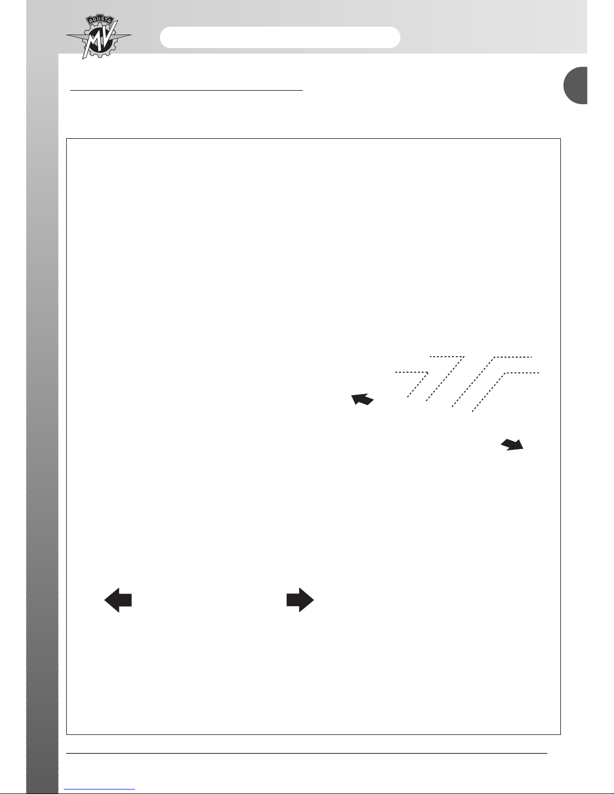
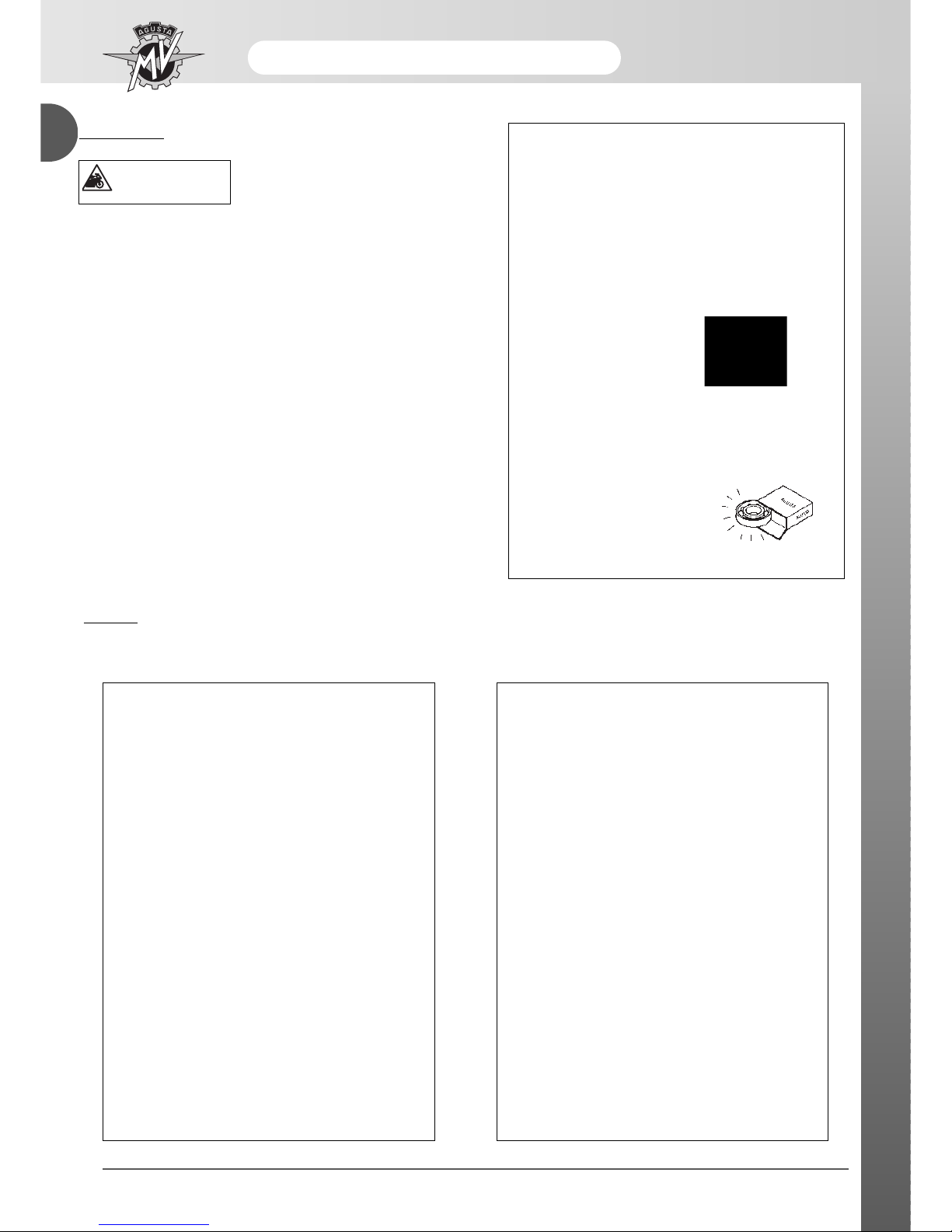
Steering pin tightening
Screw in the steering pin flange ring, without tightening.
This operation must be done manually.
Check that the steering base is at the end of its travel,
to the right.
Using the special tool tighten the ring (1) by rotating it
10° calculated approximately as one third of the
movement between the two holes of the ring (2) of the
steering head (see the figure).
Specific tool N. 800091645
Display of the operations
The operations of disassembly , assembly, removal and control are presented with the help of illustrations (designs and
photographs).
The illustrations contain symbols that indicate the procedure, special tools and other information. See the symbols lists
for their significance.
The procedures are described step after step.
PURPOSE OF THE MANUAL
Principally, this manual has been written for MV Agusta dealers and qualified mechanics.
It is not possible to document all the knowledge necessary for a mechanic in a manual. Those who utilise it must have a
basic knowledge of mechanical concepts and the inherent procedures in the techniques of repairing motorcycles. Without
this knowledge, The maintenance and repair operations can render the motorcycle unsafe for use.
Updates
MV Agusta S.p.A. is committed to a policy of continuous updating of the models produced. The modifications and
significant changes to the specifications and the procedures will be communicated to the official dealers and will
appear in future editions of this manual.
All information, instructions and technical data included in this manual are based upon information on the product
updated at the moment of going to print. MV Agusta S.p.A. reserves the right to carry out changes at any moment
without prior notice and without incurring any obligation.
- 4 -
General description
A
This signifies that the lack of
or the incomplete observance of this advice can be gravely dangerous for your
safety and for the safety of
other persons.
ATTENTION
This signifies that the lack of
observance of these instructions can bring the risk of
damage to the motorcycle
and the equipment.
Supplies key information for the best fulfilment of the operation.
N.B.
Utilise a specific tool or equipment for
the correct carrying out of the operation
described.
Tighten to the specified torque.
Tolerance or limit of use.
Utilise the tester.
Use the recommended oil.
Use the recommended grease.
Use the recommended brake fluid
Use the recommended suspension fluid.
Use the recommended coolant.
Use the recommended thread-locking
fluid.
Use the recommended sealant.
Use the recommended adhesive.
Carry out accurate cleaning.
Use new components.
Substitute the component.
Do not leave litter about.
The information marked with this symbol
refer to the F4 Brutale model series ORO.
GLOSSAR
Y AND SYMBOLS
WARNING
★
General description
- 5 -
Lato DX
Cilindro 4
Lato SX
Lato DX
Lato SX
Cilindro 3
Cilindro 1
Cilindro 2
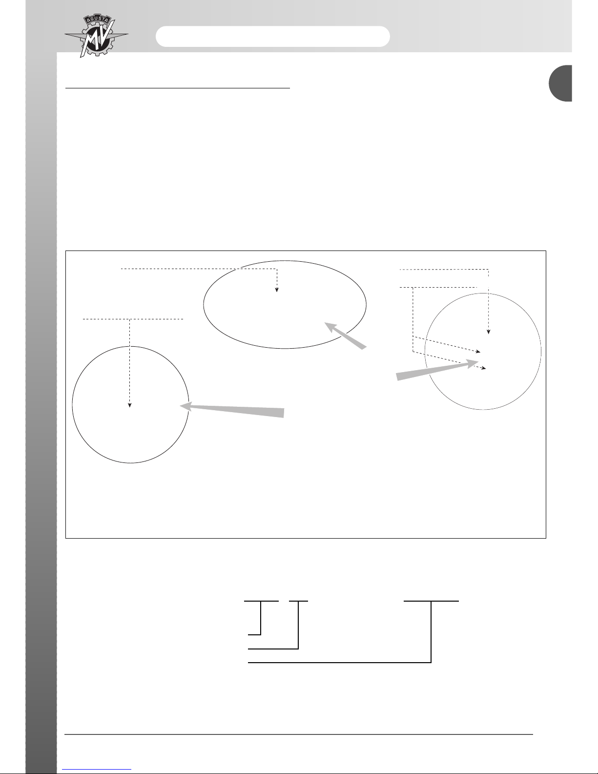
RIGHT HAND
AND LEFT HAND STANDARD
In order to specify the right/left convention used within the chapters of this manual, see the following motorcycle
and engine scheme where all sides which refer to are reported.
A
Cylinder 4
Cylinder 3
Cylinder 1
Cylinder 2
Right side
Left side
Right side
Left side
- 6 -
General description
A
SAFETY
Carbon Monoxide
• Exhaust gases contain carbon monoxide (CO) that is poisonous. Carbon monoxide can cause the loss of consciousness and death.
• If it is necessary to switch on the engine, check that the environment is well ventilated. Never switch on the engine
in an enclosed environment.
• Switching on the engine can only be carried out in an enclosed environment when there are the appropriate devices
for the evacuation of exhaust gases.
Petrol
• Petrol is extremely inflammable and under certain conditions can be explosive.
• Keep sources of heat, sparks and flames away from the work area.
• Always work in a well-ventilated area.
• Never use petrol as a cleaning solvent. Generally, avoid handling it unless it is absolutely necessary.
• Do not use petrol for cleaning components by using compressed air.
• Keep petrol out of reach of children.
Engine oil
• Engine oil can cause skin illnesses if in constant and long contact with the skin.
• If the skin comes into contact with engine oil, wash the parts affected as soon as possible with soap and water.
• If engine oil comes into contact with the eyes, abundantly rinse with water and consult a doctor immediately.
• If engine oil is swallowed, do not provocate vomiting to avoid the aspiration of the product into the lungs. Transport
the injured person immediately to hospital.
• Used oil contains dangerous substances and poisonous for the environment. To substitute oil, it is recommended to
go to an authorised MV Agusta dealer who is equipped to deal with the collection of used oil in respect of the norms
in force.
• Do not dispose of used oil in the environment.
• Keep used oil out of the reach of children.
Engine coolant
• Under certain situations, the ethylene glycol contained in the engine coolant is inflammable and its flame is invisible.
Ethylene glycol would cause serious burns if ignited because it is invisible.
• Avoid bringing the engine coolant into contact with hot parts. Such parts could be sufficiently hot to ignite the coolant.
• The engine coolant (ethylene glycol) can cause irritation of the skin and is poisonous if swallowed.
• If the engine coolant comes into contact with the skin, immediately remove any contaminated clothing and wash with
soap and water. If it comes into contact with the eyes, abundantly rinse with clean water and immediately consult a
doctor. If swallowed, do not provocate vomiting to avoid the aspiration of the product into the lungs. Administer clean
water and transport the injured person immediately to hospital and show the product to the doctor.
• If exposed to high concentrations of vapour, transport the injured person to a non-poisonous atmosphere and if
necessary call a doctor.
• Do not remove the radiator cap when the engine is still hot. Being under pressure, the engine coolant can be violently ejected and therefore provocate burns.
• The engine coolant contains dangerous and poisonous substances and is therefore dangerous for the environment.
To substitute used engine coolant, it is advisable to go to the authorised MV Agusta dealer who is equipped to deal
with the collection of used engine coolant in respect of the norms in force.
• Do not dispose of engine coolant in the environment.
• Keep engine coolant out of reach of children.
ATTENTION
The information contained in this paragraph is fundamental so that the operations carried
out on the motorcycle can be conducted with minimum risk to the mechanic.

General description
- 7 -
A
Brake fluid
• Brake fluid is extremely corrosive.
• Avoid any contacts with the eyes, skin and the mucous membrane.
• If brake liquid comes into contact with the skin, remove all contaminated clothing and wash immediately with soap
and water.
• If brake fluid comes into contact with the eyes, abundantly rinse with water and call a doctor.
• If swallowed, do not provocate vomiting to avoid aspiration of the product into the lungs. Immediately call a doctor.
• Take the injured person immediately to hospital, if he has breathed brake fluid into the lungs.
• In the case of exposure to high concentrations of vapour, move the injured person to a non-poisonous atmosphere
and if necessary call a doctor.
• In the case of accidental contact, rinse abundantly with water and call a doctor.
• Keep brake fluid out of reach of children.
Thread-locking fluid
• As it is not classified as dangerous, the prolonged contact with the skin, particularly with regards to abrasions can
provocate sensitiveness and dermatitis. In the case of contact with the skin, rinse abundantly with running water.
• Move the injured person into the open air and call a doctor if the injured person feels ill after having breathed in the
product.
• In the case of contact with the eyes, rinse abundantly with water for at least 15 minutes.
• If the thread-locking fluid has been swallowed, drink an abundant quantity of water or milk. Do not provocate vomiting to avoid the aspiration of the product into the lungs. Immediately call a doctor.
• Keep out of reach of children.
Nitrogen - rear shock absorber
• The rear shock absorber contains nitrogen under pressure.
• Before disposing of used shock absorbers, discharge the nitrogen via the depressurising valve.
• Utilise only nitrogen to pressurise the shock absorber. The use of unstable gases can cause explosions that could
cause burns.
• Do not place the shock absorber near to flames or sources of heat as this could cause explosions with consequent
burns.
• Keep out of reach of children.
Battery
• The battery produces explosive gases. Keep it away from sparks, flames or cigarettes. During recharging, adequately ventilate the environment.
• The battery contains a solution of sulphuric acid (electrolyte).
• Sulphuric acid is corrosive and it destroys many materials and clothing. On contact with small quantities of water it
generates a violent reaction that manifests itself by creating large quantity of heat and spurts of hot acid. Sulphuric
acid attacks many metals thereby liberating hydrogen: an inflammable gas that forms an explosive mixture when
mixed with air.
• Contact with sulphuric acid can cause burns. In the case of contact, remove immediately all contaminated clothing
and wash the skin with abundant quantities of water. Take the injured person to hospital if necessary.
• In the case of contact with the eyes, rinse immediately with abundant water. Call a doctor and continue with the treatment until the doctor arrives.
• If the electrolyte is swallowed, rinse the mouth with water without swallowing. Take the injured person immediately
to hospital and explain to the doctor there what the injured person has swallowed.
• The battery contains dangerous substances that are poisonous for the environment. It is advisable to substitute it at
an MV Agusta dealer that is equipped to dispose of this product in respect of the norms in force.
• Do not dispose of used batteries in the environment.
• Keep out of reach of children.
Hot parts
• The engine and the exhaust system become very hot and maintain this temperature for some time after the engine
has been switched off. Wait for these parts to cool down before handling them or working on the motorcycle near to
them. Use protective gloves.
- 8 -
General description
A
GENERAL INDEX
SUMMARY OF EACH CHAPTER
INDEX
WARNING
The information contained in this
paragraph is important so that the
operations carried out on the
motorcycle can be conducted without damaging the motorcycle.
• Thoroughly clean the motorcycle before disassembling it.
• During disassembly, clean all parts and place them in containers respecting exactly the order of disassembly.
• Always use the special utensils where necessary and
each time where prescribed.
• Always use adhesives, sealants and lubricants where prescribed. Respect the instructions about their technical
characteristics.
• Always substitute parts such as gaskets, O-rings, security
washers with new parts.
• Loosening and tightening nuts or screws, always start
from the bigger ones or the centre. Always comply with the
torque wrench settings.
• Utilise only MV Agusta spare parts.
WARNING
General description
- 9 -
A
OPERA
TIVE TECHNICAL SPECIFICATIONS
MOTORCYCLE IDENTIFICATION
1) Frame registration number
2) Engine registration number
3) Homologation date
4) "Limited series" number
★
The registration number of the motorcycle is stamped on the right side of the steering head.
The engine part number is stamped on the top half casing near the fork.
2) numero di matricola motore
4) numero "serie limitata"
1) numero di matricola telaio
3) dati di omologazione
★ Only for the F4 BRUTALE series ORO: the pre-
sence of the nameplate indicates that the motorcycle has been constructed on a limited series basis.
Each example is identified by a progressive number stamped on a nameplate in 24 carat gold.
ZCG F4 01 AA Y V 000000
Manufacturer identification
Vehicle model
Progressive frame number
Below is an example of the designation of the frame registration number:
1) Frame registration number
2) Engine registration number
4) "Limited series" number ★
3) Homologation date

- 10 -
General description
A

B
- 1 -
Maintenance
SECTION B
Revision 0

- 2 -
Maintenance
B
SUMMAR
Y
TECHNICAL INFORMATION....................................................................................................................PAGE 3
TECHNICAL DATA ..................................................................................................................................PAGE 3
COMPONENTS IN CARBON FIBRE (F4 BRUTALE ORO) ....................................................................PAGE 6
MAGNESIUM COMPONENTS (F4 BRUTALE ORO) ..............................................................................PAGE 7
PERIODICAL MAINTENANCE SCHEDULE ............................................................................................PAGE 9
MAINTENANCE AND TUNING OPERATIONS........................................................................................PAGE 11
ENGINE OIL AND OIL FILTER.................................................................................................................PAGE 11
ENGINE COOLANT..................................................................................................................................PAGE 19
ELECTRIC COOLING FAN.......................................................................................................................PAGE 21
VALVE MECHANISM ADJUSTMENT ......................................................................................................PAGE 22
SPARK PLUGS.........................................................................................................................................PAGE 33
FUEL FILTERS..........................................................................................................................................PAGE 34
FUEL PUMPASSEMBLY.........................................................................................................................PAGE 44
FUEL UNION TUBES...............................................................................................................................PAGE 47
FUEL TUBES ASSEMBLY .......................................................................................................................PAGE 47
THROTTLE BODY ADJUSTMENT AND TUNING ..................................................................................PAGE 50
AIR FILTER...............................................................................................................................................PAGE 57
BRAKES AND CLUTCH...........................................................................................................................PAGE 60
BRAKE/CLUTCH/GEARCHANGE COMMANDS CHECK............................................................................PAGE 63
BRAKE PADS...........................................................................................................................................PAGE 65
ACCELERATOR CONTROL.....................................................................................................................PAGE 65
LOCKS .....................................................................................................................................................PAGE 67
STEERING ................................................................................................................................................PAGE 69
TRANSMISSION CHAIN............................................................................................................................PAGE 69
TYRES ......................................................................................................................................................PAGE 72
FRONT WHEEL BEARINGS....................................................................................................................PAGE 72
WHEELS ...................................................................................................................................................PAGE 73
REAR WHEEL HUB..................................................................................................................................PAGE 74
OSCILLA TING ARM BEARINGS .............................................................................................................PAGE 74
REAR SHOCK ABSORBER .....................................................................................................................PAGE 74
SIDE STAND.............................................................................................................................................PAGE 75
FRONT FORK...........................................................................................................................................PAGE 76
SCREWS AND NUTS ...............................................................................................................................PAGE 76
TUBE BAND FASTENERS.......................................................................................................................PAGE 76
ELECTRICAL SYSTEM .............................................................................................................................PAGE 77
BA TTER Y...................................................................................................................................................PAGE 77
INSTRUMENTS AND WARNING LIGHTS...............................................................................................PAGE 80
LIGHTS......................................................................................................................................................PAGE 85
FRONT HEADLAMP.................................................................................................................................PAGE 92
B
Maintenance
- 3 -
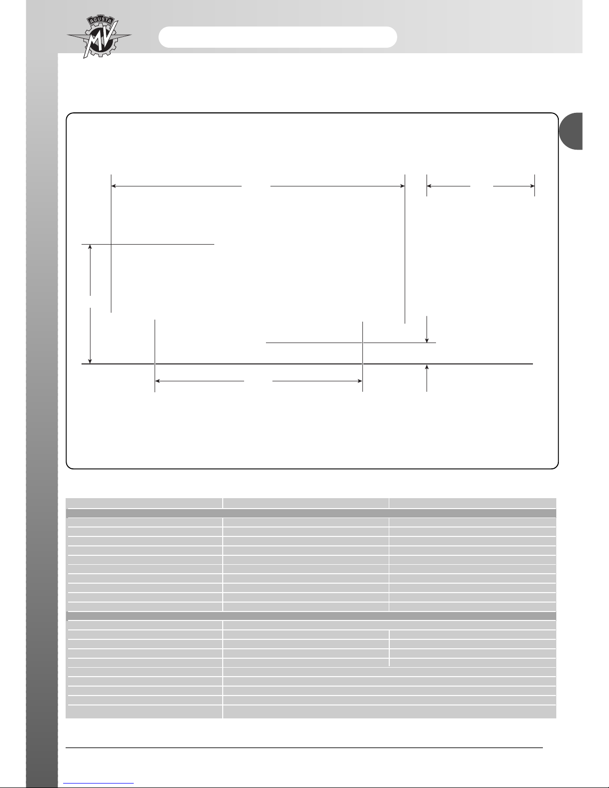
2020
1410
135
805
760
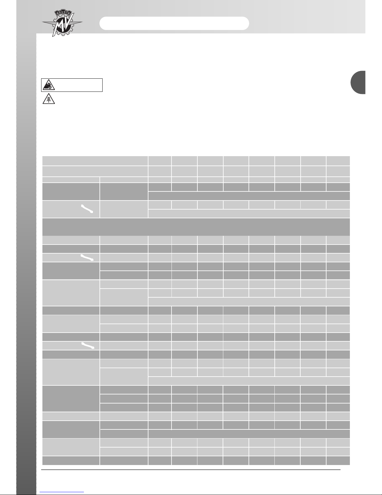
TECHNICAL INFORMATION
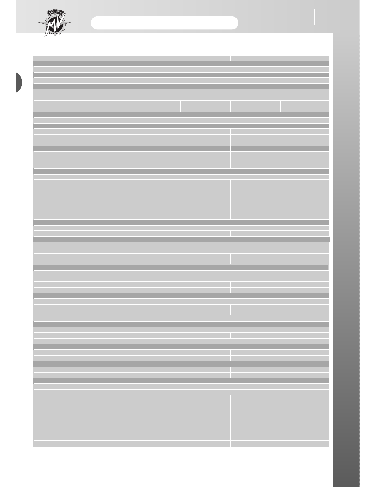
TECHNICAL DATA
Description BRUTALE ORO BRUTALE S
CHARACTERISTICS
Wheelbase (mm) (*) 1410 1410
Total length (mm) (*) 2020 2020
Maximum width (mm) 760 760
Seat height (mm) (*) 805 805
Ground clearance (mm) (*) 135 135
Trail (mm) (*) 101.5 101.5
Dry weight (kg) 179 185
Fuel tank capacity (litres) (**) 19 19
Fuel reserve (litres) (**) 4 4
Sump oil quantity (kg) 3.5 3.5
ENGINE
Type 4 Stroke four cylinder, 16 valves
Bore (mm) 73.8 73.8
Stroke (mm) 43.8 43.8
Displacement (cm3) 749.4 749.4
Compression ratio 12 : 1 12 : 1
Starter system Electrical
Cooling Liquid with oil cooler
Engine casing and covers Die-cast
Cylinder head and cylinders Chill-cast
Valves Bi-metal/mono-metal
* : I The data declared are not binding. They are susceptible to variations due to riding conditions.
**: I The data declared are not binding. They are susceptible to variations due to external temperature, engine temperature and the evaporation point of the petrol used.
Maintenance
TECHNICAL DATA
- 4 -
Description BRUTALE ORO BRUTALE S
TIMING
Type D.O.H.C. radial valves
LUBRICATION
Type Wet sump
IGNITION – FUEL FEED SYSTEM
Type Weber-Marelli ignition/injection 1.6 M integrated system
Inductive charge electronic ignition, Multipoint electronic injection
Spark plugs (alternatively) NGK CR9 EB Champion G59c NGK CR9 EB Champion G59c
Spark gap (mm) 0.7 ÷ 0.8 0.6 ÷ 0.7 0.7 ÷ 0.8 0.6 ÷ 0.7
CLUTCH
Type Wet multi-plate
PRIMARY TRANSMISSION
N° teeth - engine crankshaft gear Z = 47 Z = 47
N° teeth - clutch gear Z = 81 Z = 81
Transmission ratio 1.72 1.72
SECONDARY TRANSMISSION
N° teeth – pinion wheel Z = 14 Z = 14
N° teeth – crown wheel Z = 41 Z = 41
Transmission ratio 2.93 2.93
GEAR CHANGE
Type Extractable six speed, with gearing always inserted
Gear ratios (total ratios)
1
st
2.92 (14.71) 2.92 (14.71)
2
nd
2.21 (11.14) 2.21 (11.14)
3
rd
1.78 (8.97) 1.78 (8.97)
4
th
1.50 (7.56) 1.50 (7.56)
5
th
1.32 (6.65) 1.32 (6.65)
6
th
1.21 (6.10) 1.21 (6.10)
FRAME
Type Tubular framework in wire-drawn steel tubes 25 CrMo (TIG welding)
Fork fulcrum plates Magnesium alloy Aluminium alloy
FRONT SUSPENSION
Type
Hydraulic telescopic forks with the stems positioned upside down, equipped with
a system of external adjustment for extension, compression and spring preload
Ø stems (mm) 50 with titanium nitride treatment 50
Telescopic movement (mm) 128 128
REAR SUSPENSION
Type
Progressive, single-steering damper adjustable in extension, in compression
(high/low speed), and in spring-preloading
Mono-arm fork Magnesium alloy Aluminium alloy
Wheel travel (mm) 120 120
FRONT BRAKE
Type Floating double disk with the braking area in steel
Ø Discs (mm) 310 310
Disc flanges Aluminium Steel
Pincers (Ø pistons mm) 6 pistons (Ø 22.65; Ø 25.4; Ø 30.23)
REAR BRAKE
Type Disc type in steel
Ø Discs (mm) 210 210
Pincers (Ø pistons mm) 4 pistons (Ø 25.4)
FRONT WHEEL
Material Magnesium alloy Aluminium alloy
Dimensions 3.50” x 17” 3.50” x 17”
REAR WHEEL
Material Magnesium alloy Aluminium alloy
Dimensions 6.00” x 17” 6.00” x 17”
TYRES
Front 120/65-ZR 17 (56 W)
Rear 190/50-ZR 17 (73 W) o 180/55-ZR 17 (73 W)
Brand and type PIRELLI - Dragon Evo MTR 21 Corsa (Ant.)
PIRELLI - Dragon Evo MTR 22 Corsa (Post.)
DUNLOP - Sport Max D 207 PIRELLI - Diablo Corsa
Race Replica MICHELIN - Pilot Sport
MICHELIN - Pilot Power
DUNLOP - Sport Max D 207 Race Replica
Tyre pressures (*)
Front 2.3 bar (33 psi) 2.3 bar (33 psi)
Rear 2.3 bar (33 psi) 2.3 bar (33 psi)
* : In the event of different make tyres being used as opposed to those advised, refer to the pressure values marked on the side of the tyre by the manufacturer.
Maintenance
- 5 -
TECHNICAL DATA
Description BRUTALE ORO BRUTALE S
ELECTRICAL SYSTEM
Voltage 12V 12V
Front dipped beam light bulb 12V 55W 12V 55W
Front main beam light bulb 12V 60W 12V 60W
Front sidelight bulb 12V 5W 12V 5W
Rear light bulb 12V 5W 12V 5W
Rear stop light bulb 12V 21W 12V 21W
Direction indicators 12V 10W 12V 10W
Battery 12V - 9Ah 12V - 9Ah
Alternator 650W a 5000 r.p.m. 650W a 5000 r.p.m.
BODYWORK
Tank Thermo-plastic material Thermo-plastic material
Air filter compartment conveyors Carbon fibre Thermo-plastic material
Tank side panel Carbon fibre Thermo-plastic material
Tail unit rear side panel Carbon fibre Thermo-plastic material
Tail unit Carbon fibre Thermo-plastic material
Instrumentation protection Carbon fibre Thermo-plastic material
Ignition switch cover Carbon fibre Thermo-plastic material
Exhaust tube protection Carbon fibre Thermo-plastic material
Chain guard Carbon fibre Thermo-plastic material
Oil cooler protection Carbon fibre Thermo-plastic material
Number plate carrier Thermo-plastic material Thermo-plastic material
Rear-view mirrors Thermo-plastic material Thermo-plastic material
Protezione tubo scarico Aluminium Aluminium
- 6 -
Maintenance
B
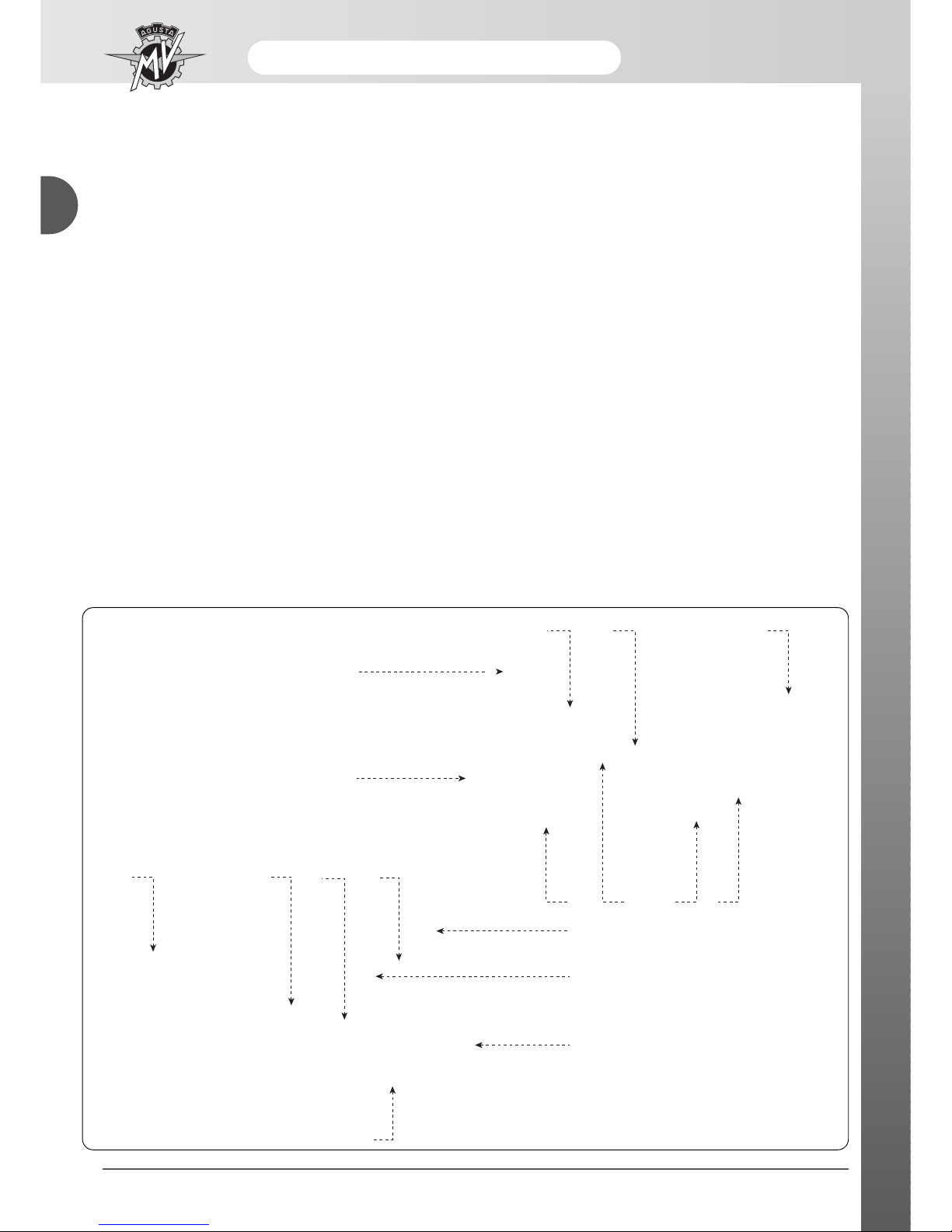
★ COMPONENTS IN CARBON FIBRE (F4 BRUTALE ORO)
9
3
2 94
58
7
1
10
13
10
7
1213 6 11
8 - Ignition switch cover
9 - Tail unit
10 - Front mudguard
11 - Top chain protection
12 - Lower chain protection
13 - Oil cooler protection
1 - Right air filter compartment side panel
2 - Left air filter compartment side panel
3 - Right tank side panel
4 - Left tank side panel
5 - Right cylinder cover
6 - Left cylinder cover
7 - Instrument panel protection
Maintenance
- 7 -
B
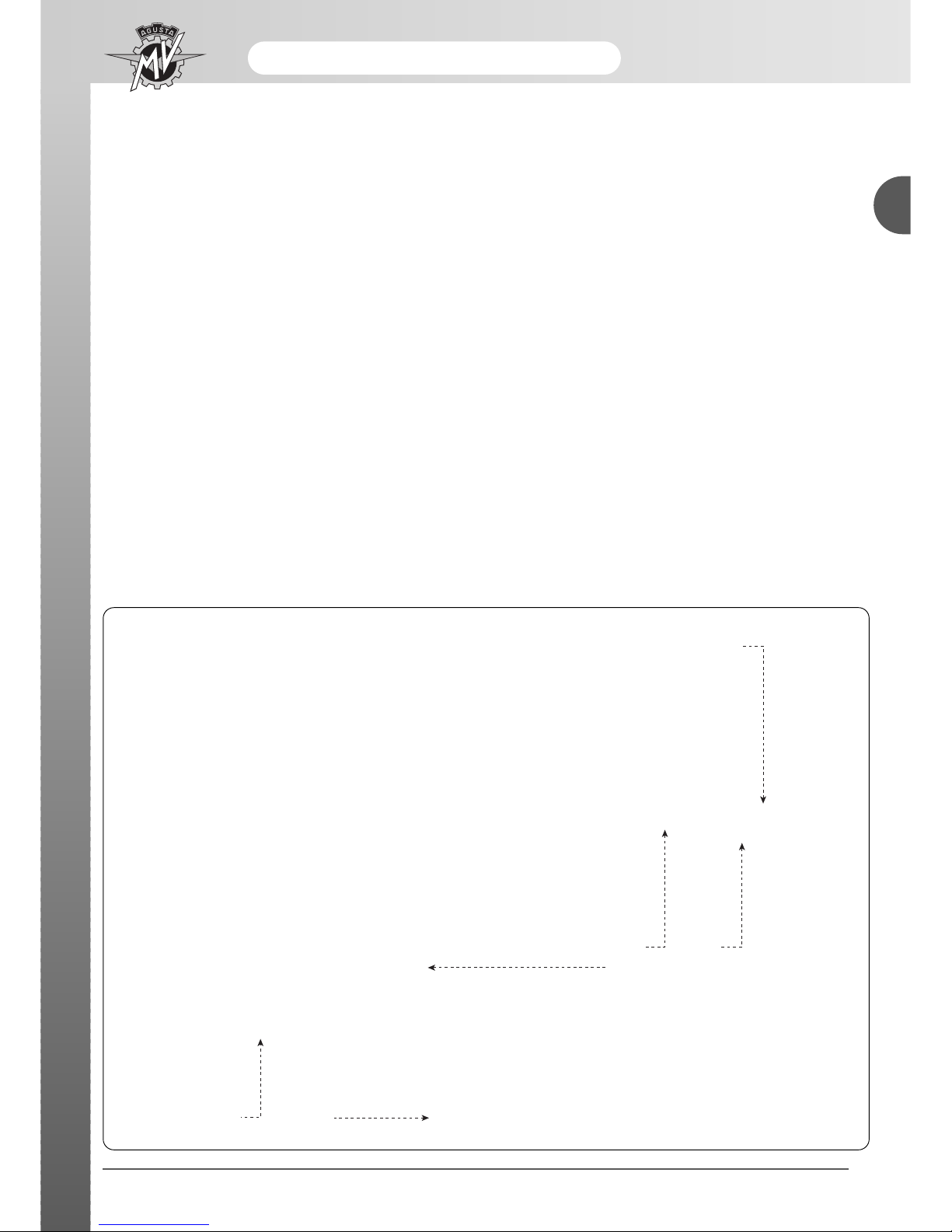
★ MAGNESIUM COMPONENTS (F4 BRUTALE ORO)
1 - Steering base
2 - Frame side plate
3 - Front wheel rim
4 - Rear wheel rim
5 - Mono-arm fork
4
1
23
2 5

- 8 -
Maintenance
B
Manutenzione
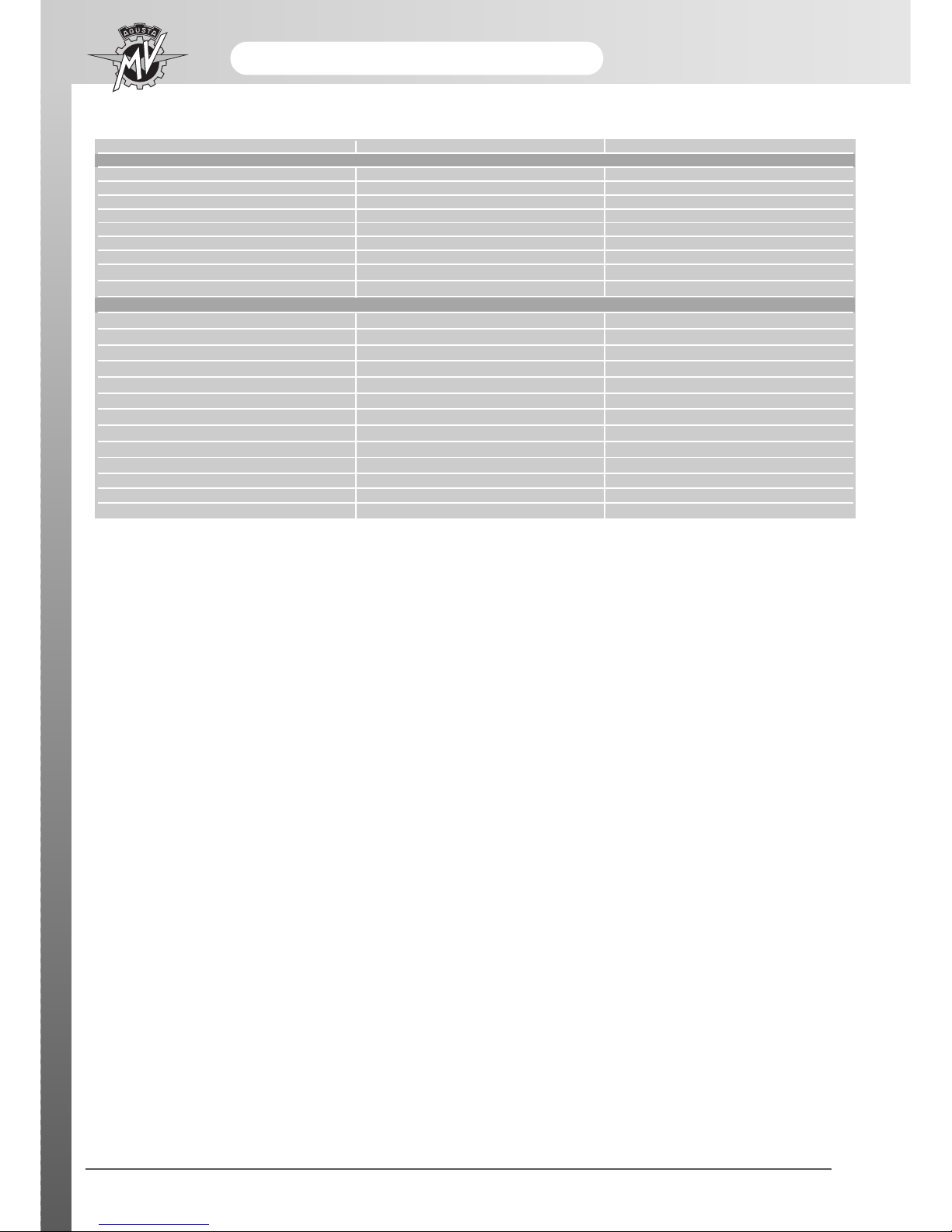
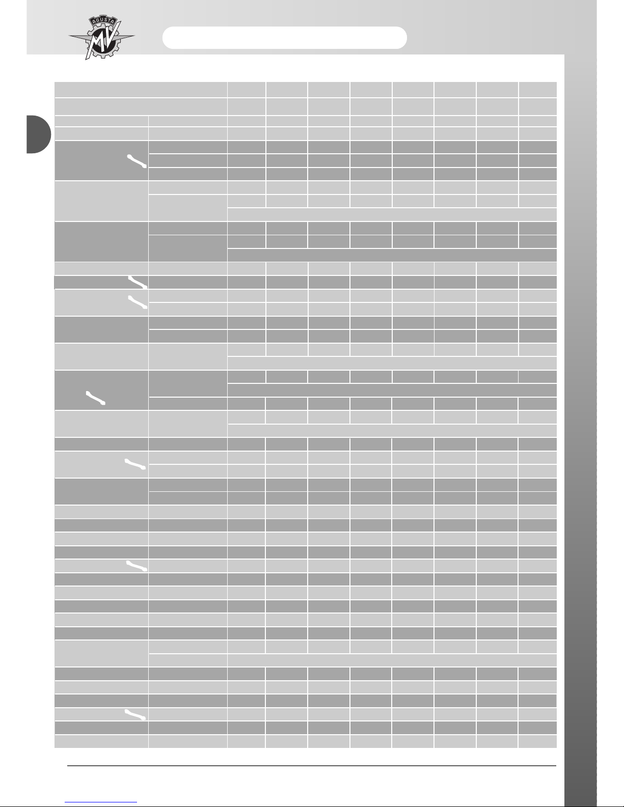
PERIODICAL MAINTENANCE SCHEDULE
The following table shows the recommended intervals for the interventions of periodical maintenance. Periodical
maintenance is necessary to keep the motorcycle in an optimum condition. The intervals are expressed in kilometres.
For motorcycles used in particularly severe conditions, maintenance operations must be
carried out more frequently.
We respect and defend the environment.
Everything that we do has repercussions on the whole planet and on its resources.
MV Agusta, to protect the interests of the everyone, ask clients and technical assistance operators to use
the motorcycle and dispose of its used parts with respect to the norms in force in terms of environmental
pollution, disposal and recycling of refuse.
★ The information marked with this symbol refers only to the F4 BRUTALE model
series ORO.
WARNING
Maintenance
- 9 -
B
0 1000 6000 12000 18000 24000 30000 36000
(600) (3800) (7500) (11200) (14900) (18600) (22400)
Pre-
delivery
Description Operation
Km (mi) covered
Service
AB C DE F G
Programmed maintenance schedule
Substitution
(Utilise only originali MV
Agusta oil filters)
Cleaning of contact lever /
pump piston area
( front and rear )
Engine oil Substitution
●●●●●●●
At least once a year
Engine oil filter
●●●●●●●
At every substitution of engine oil
Engine coolant
Check level and top-up
●●●●●●●●
Substitution At least every two years
Cooling system Check for leakages ●●●●●●●●
Electric fan Check functioning ●●●●●●●●
Valves Check / adjustment ●●●●
Timing chain
Check ●●●
Substitution ●
Pattino mobile distribuzione
Check / Substitution ●●●
Substitution
●
At least every substitution of the timing chain
Timing chain tensioner Check / Substitution ●●●
Spark plugs
Check / Substitution ●●●●
Substitution ●●●
Fuel filter Check / Substitution ●●●
Throttle body Check and adjust ●●●●●●●
Air filter Check / Substitution ●●●●●●
Fluido freni e frizione
Check level ●●●●● ●●
Substitution
●
At least every two years
Check functioning ●●●●●●●●
Brakes and clutch Check circuit ●●●●●●●●
●●●●●●●●
Brake pads
Check / Substitution ●●●●●●●
Fuel tubes
●●●●●●●
Substitution At least every three years
Accelerator control
Check functioning ●●●●●●●●
Check/adjust play ●●●●●●●●
Starter control Check functioning ●●●●●●●●
Mobile timing chain guide
Brake and clutch fluid
Check for defects and
leakages
- 10 -
Maintenance
B
Manutenzione
Programmed maintenance schedule
Frequenza Km (mi)
Tagliando
AB C DE F G
lubricate roller
bearings and
guides
lubricate roller
bearings and
guide
0 1000 6000 12000 18000 24000 30000 36000
(600) (3800) (7500) (11200) (14900) (18600) (22400)
Pre-
delivery
Description Operation
Cleaning of contact lever
area with side stand
Transmission and flexible controls Check / Adjust ●●●●●●●●
Check / Adjust ●●●●●●●●
Transmission chain Lubricate ●●●●
Substitution
★★
● ★★● ★★●
Check ●●●●
Pinion wheel/stop washer
Substitution
★★● ★★
● ★★●
At least at each substitution of the transmission chain
Check ●●●●
Crown wheel
Substitution
★★● ★★● ★★●
At least at each substitution of the transmission chain
Crown wheel tension regulator Check
★★● ★★● ★★●
Steering head flange ring Check / Adjust ●●●●
Steering bearings
Check / Adjust ●●●●
Lubricate ●
Tyres
Check for pressure ●●●●●●●●
Check for wear ●●●●●●●
Wheel rims Visual check
●●●●●●●
Every tyre substitution
Check
●●●●●
Front wheel bearings
Every tyre substitution
Substitution ●
Parts in magnesium
Visual check for knocks
★ ★ ★ ★ ★ ★ ★
and scratches
★ At least every six months
Side stand Check functioning ●●●●●●●●
Side
Check functioning ●●●●●●●●
stand switch
●●●●●●●●
Rear wheel hub
Check / ●●
Substitution /
●
Rear fork bearings Check / lubricate ●
Rear fork chain guide Check / substitution ●●●●●●●
Chain guide frame plate Check / substitution ●●●●●●●
Rear shock absorber Check / Adjust ●●●●
Front fork oil Substitution ●
Battery connections Check and clean ●●●●●●●
Electrical system Check functioning ●●●●●●●●
Instrument Check functioning ●●●●●●●●
Lights/visual signals Check functioning ●●●●●●●●
Horn Check functioning ●●●●●●●●
Front headlight
Check functioning ●●●●●●●●
Adjust At every variation of the riding set-up of the motorcycle
IIgnition switch Check functioning ●●●●●●●●
Locks Check functioning ●●●●●●●●
Torque settings – nuts and bolt Check / tightness ●●●●●●●●
Tube band fasteners Check / tightness ●●●●●●●●
General lubrication ●●●●●●●●
General check ●●●●●●●●
Km (mi) covered
Service
Maintenance
MAINTENANCE AND TUNING OPERATIONS
Each operation of periodical maintenance is described
in this chapter.
ENGINE OIL AND OIL FILTER
Engine oil
Substitute:→ at the first 1000 kilometres and then
every 6000 kilometres
Oil filter
Substitute:→ at the first 1000 kilometres and then
every 6000 kilometres (or at least
every oil change)
To accede to the oil filter and the discharge and filling
holes of the engine oil, it is necessary to carry out certain operations beforehand:
n Place the motorcycle on the rear stand.
The substitution of the engine oil must
be done with a hot engine as opposed to
the oil-check that is done with a cold
engine.
Place a container underneath the engine to collect the
used oil.
Remove the oil discharge plug (1).
Recover the oil in an appropriate container.
Do not scatter the drainage oil into the environment.
- 11 -
B
N.B.
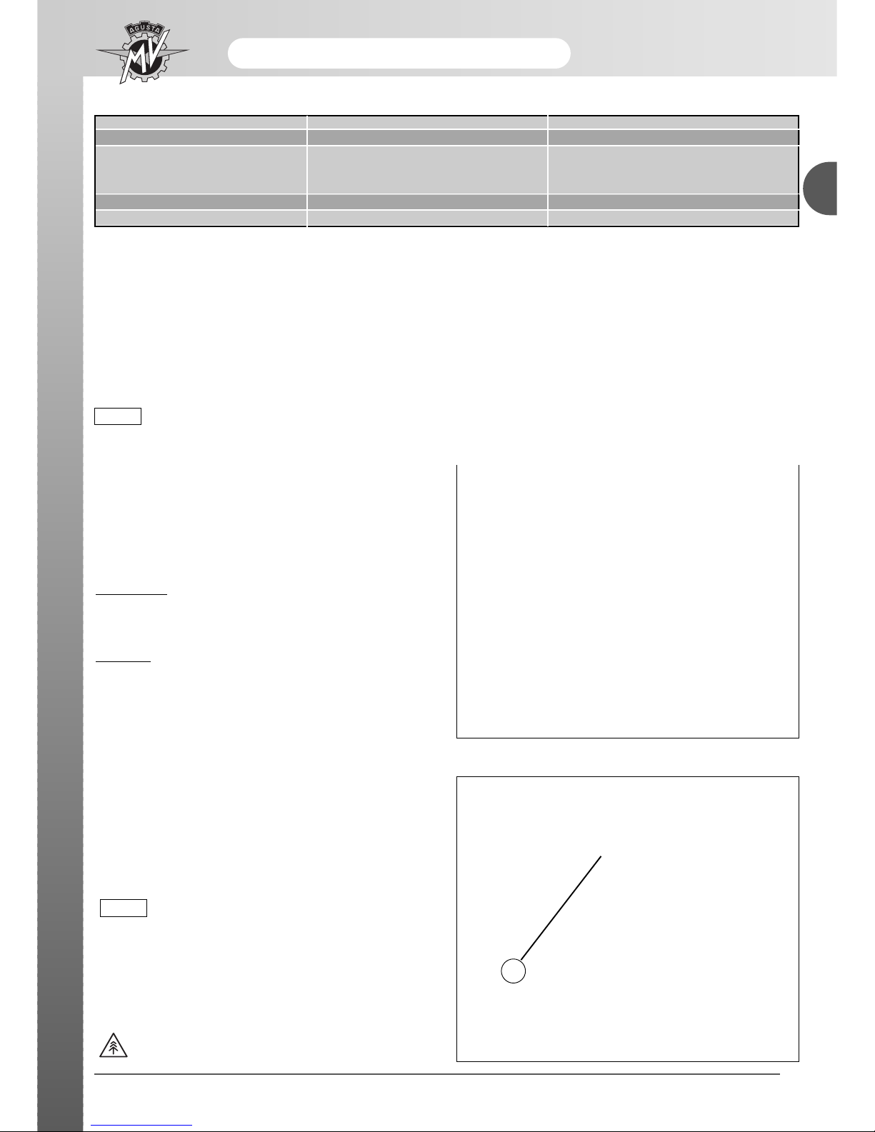
Description Recommended product Specification
Engine oil AGIP RACING 4T 10W/60 (*) SAE 10W/60 - API SJ
Ethylene-glycol
Engine coolant AGIP ECO - PERMANENT diluited with 40%
distilled water
Brake and clutch fluid AGIP BRAKE FLUID DOT4 DOT4
Chain lubrication oil MOTUL CHAIN LUBE PLUS –
Table of lubricants and fluids
*
: To find the recommended product, MV Agusta suggests going directly to the authorised MV Agusta dealers.
AGIP Racing 4T 10W/60 has been manufactured for the F4 engine. If the described oil is not available, MV
Agusta suggests using completely synthetic oils with characteristics that
conform or exceed the following norms:
– Conforming to API SJ
– Conforming to ACEAA3
– Conforming to JASO MA
– Grade SAE 20 W-50 o 10 W-60
The above specifications indicated are marked either on their
own or together with others on the container of the lubricating
oil.
Engine oil
SAE 10 W-60
API SJ
ACEA A3
JASO MA
N.B.
1

- 12 -
Maintenance
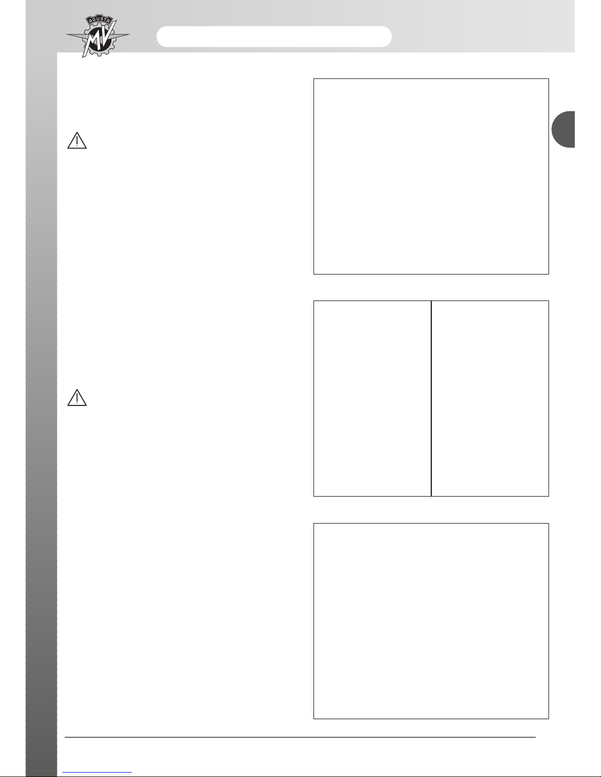
B
1
Remove the oil filler plug (1) on the right side of the
motorcycle so that it facilitates the discharge of the
used oil.
Wait until the lubrication system is completely empty of
used engine oil.
Substitution of the oil filter
In order to proceed to replace the oil filter you should
remove the exhaust manifolds of the cylinders 3 and 4.
Release the two side clamps of the oil cooler.
Unscrew the lower fixing screws of the oil cooler protection on the lower basis of the water radiator.
Remove the oil cooler protection.

Maintenance
Slightly move the coolers towards the front area of the
motorcycle, then unscrew the nut on the fixing flange of
the exhaust manifilds of the cylinder group.
During this operation pay attention to the
exhaust pipes in order to avoid from scorching.
Release the union spring between compensator and
manifolds of cylinders 3 and 4.
- 13 -
B
20÷22 N•m
Remove the manifold of cylinders 3 and 4.
In order to facilitate the reassembly of the
manifolds you should place the fixing flange on the manifolds before these
manifolds are pleced on the engine.
Insert the flange in the manifolds and then
turn it.
Place the flange-manifolds assembly on
the fixing stud, then tighten the check nut
to the torque wrench shown.
Torque wrench of exhaust manifold check
nut: 20÷22 Nm
N.B.

- 14 -
Maintenance
B
Loosen the safety clamp and remove it.
Unscrew the oil filter by an appropriate wrench.
In the event of a filter branded TOYO ROKI use the
wrench for oil filter:
TOYO ROKI
FACOM D. 139 tool
Part code 8000A4317
In the event of a filter branded Champion use the wrench for oil filter:
Champion
Part code N° 800099010
Clean accurately any oily parts.
Using a clean cloth to clean accurately the area and
the filter face.
Take out the oil filter from the new engine oil filter kit.
- Toyo Roki oil filter kit: Part code 8000A3702
- Champion oil filter kit: Part code 8000A1428
Only use original components of MV Agusta.
If you use an oil filter Toyo Roki (Part code
8000A3702), you should the following preliminary operation.
Take out the gasket from the engine oil filter kit of new
equipment and insert on the filter as shown in the figure on the left.
Only use a new gasket.
Slide the gasket up to bring in contact with the oil filter
back ring (see figure on the right).
Lubricate the gasket on the filter with engine oil.
Maintenance
- 15 -
B
- 16 -
Maintenance
B
Insert the filter in its seat.
Turn the filter manually until the gasket is into slight
contact with the machined surface.
Tighten the filter using the appropriate tool and a torque wrench.
- TOYO ROKI oil filter:
FACOM D. 139 tool
Part code 8000A4317
Oil filter torque wrench:
24 N·m
- Champion oil filter:
Tool code 800099010
Oil filter torque wrench:
15 N·m
After having tightened the filter, take out the clamp for
engine oil filter and its screw from the new oil filter kit.
Only use a new clamp.
Insert the clamp and slide it until it brings in contact
with the oil filter back ring.
TOYO ROKI:
24 N•m
Champion:
15 N•m
 Loading...