

Mtd OEM-190-841 owners guide

Operator’s Manual
Mulch Kit
For Garden Tractors with a 54-inch Deck
Model
OEM-190-841
MTD LLC, P.O. BOX 361131 CLEVELAND, OHIO 44136-0019
PRINTED IN U.S.A.
FORM NO.
770-10591.fm
(1/02)
CALLING CUSTOMER SUPPORT
If you have difficulty assembling this product or have any questions regarding the controls, operation or
maintenance of this unit, please call the Customer Support Department.
Call 1- (330) 220-4MTD (4683) or 1- (800)-800-7310 to reach a Customer Support representative.
Please have your unit’s model number and serial number ready when you call. See previous section
to locate this information. You will be asked to enter the serial number in order to process your call.
For more details about this unit, visit our website at www.mtdproducts.com
CONTENTS OF CARTON
Before beginning installation, remove all parts from the
carton to make sure everything is present. Carton
contents are listed below. Part numbers are shown in
parentheses.
SECTION 1: INSTALLATION
NOTE: References to LEFT and RIGHT indicate the left
and right sides of the tractor when facing forward in the
operator’s position. Reference to the FRONT indicates
the grille end; to the REAR the drawbar end.
WARNING: Before beginning installation,
place the tractor on a firm and level
surface. Place the PTO in the disengaged
(OFF) position, stop the tractor engine and
set the parking brake.
WARNING: Cutting blades are sharp.
Always protect hands by wearing heavy
leather work gloves to grasp blades.
Mounting The Mulching Blades
• Remove the cutting deck from beneath the tractor,
(refer to DECK REMOVAL in the MAINTENANCE
section of your tractor’s Operator’s Manual for
detailed instructions) then gently flip the deck over
to expose its underside.
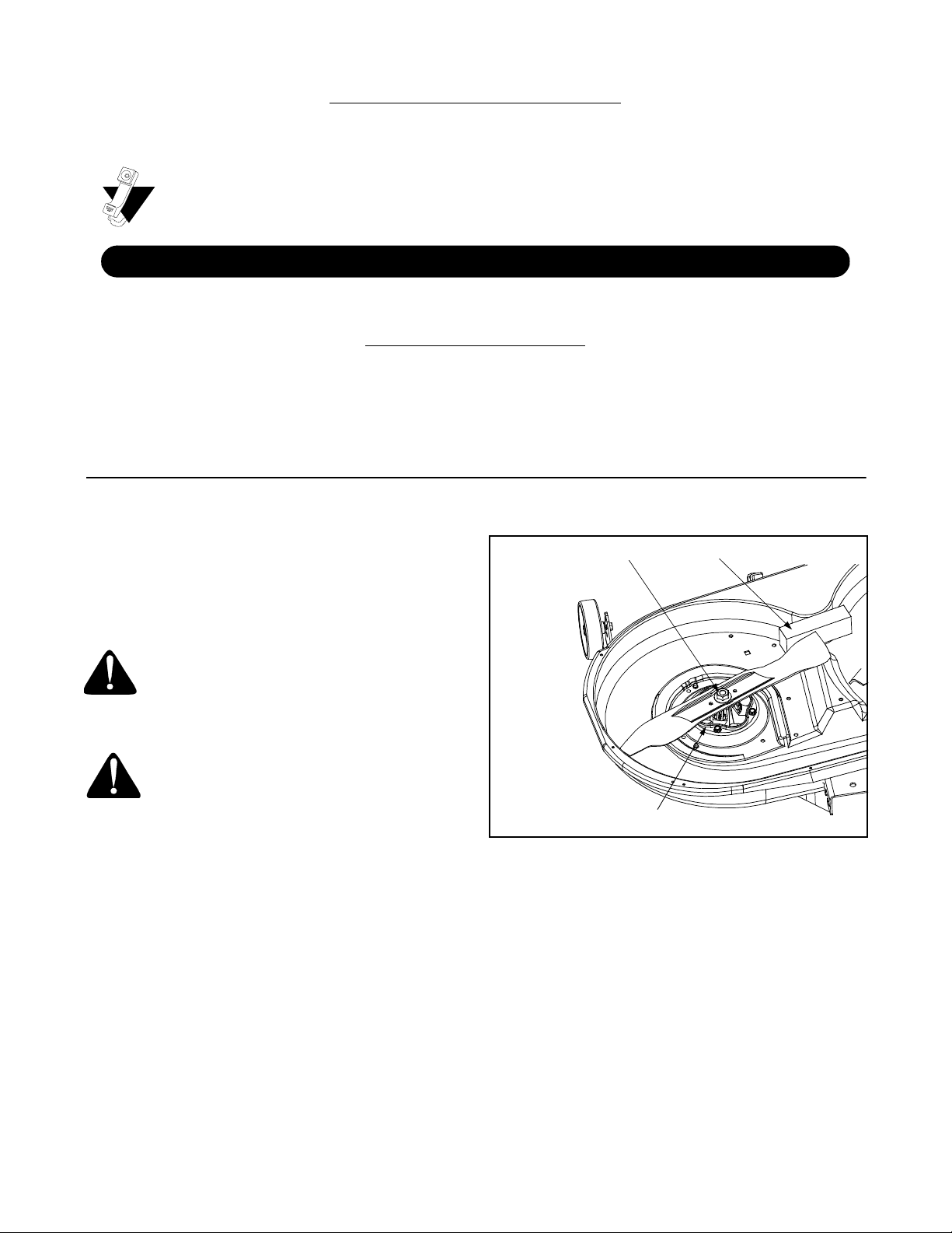
• Place a block of wood between the center deck
housing baffle and the cutting blade to act as a
stabilizer. See Figure 1.
• Use a 15/16" wrench to remove the hex flange nut
that secures the blade to the spindle assembly.
NOTE: The hex flange nut has a right-handed thread
pattern. Do NOT attempt to force the nut in the incorrect
direction. Doing so may damage the nut and create a
safety hazard.
One Mulching Baffle (603-0396)
Three 18.50” Mulching Blades (742-0678)
Three 3/8-16 Flange Lock Nut (712-0431)
Two 3/8-16 x 2.75 Hex Cap Screw (710-3022)
One 3/8-16 x 1.75 Hex Cap Screw (710-0347)
Hex Flange Nut
Spindle Assembly
• Install the new blades packed with the mulcher. Be
sure to install the blade with the side of the blade
marked ‘‘Bottom’’ (or with a part number stamped in
it) facing the ground when the mower is in the
operating position.
IMPORTANT:
spindle hex flange nut to between 70 foot-pounds and
90 foot-pounds.
• Remount the cutting deck.
Use a torque wrench to tighten the blade
Wood Block
Figure 1
Inserting The Mulch Plug
• After mounting the new blades, remove the chute
deflector and insert the mulching baffle into the
discharge opening.
2
 Loading...