

Page 1

To The Owner • Carton Contents • Assembly • Parts Lists • Warranty
Assembly Instructions
Rear Mount Weight Kit
READ SAFETY RULES AND INSTRUCTIONS CAREFULLY BEFORE OPERATION
PRINTED IN U.S.A.
Model 218
IMPORTANT
MTD LLC, P.O. BOX 361131 CLEVELAND, OHIO 44136-0019
FORM NO. 769-03184
07/02/2007
Page 2

These Installation instructions are an important part of your new rear mount weight kit. This infor-
mation will help you assemble, prepare and maintain the unit for best performance. Please read
and understand this material prior to using this equipment.
TABLE OF CONTENTS
1. Rider Model Identification ................................ Page 3
2. Carton Contents .............................................. Page 4
3. Bracket Assembly & Attachment ..................... Page 6
4. Parts List.......................................................... Page 7
Warranty Information
For warranty information regarding this product, refer to your tractor owner’s manual.
Customer Support
Please do
purchased, without first contacting Customer Support.
If you have difficulty assembling this product or have any questions regarding the controls, operation, or maintenance of this
unit, you can seek help from the experts. Choose from the options below:
• Visit
• Phone a Customer Support Representative at 1-800-800-7310.
• Please have your unit’s model number and serial number ready when you call. See previous section to locate this information.
mtdproducts.com. Click on the Service & Support menu option.
You will be asked to enter the serial number in order to process your call.
NOT
return the unit to the retailer from which it was
2
Page 3

Model Plate
Rear Mount Weight Kit
The Model 218 Rear Mount Weight Kit is designed for
use on all MTD Step-thru™ series tractors.
NOTE: An adapter kit (753-05585) is available for
installation of this weight kit on 700 series riders. Call
1
6
3
0
3
13
8
1
1
4
6
4
1
3
4
6
H
7
-
-
O
3
C
,
0
0
L
D
X
2
N
L
0
O
A
2
8
B
L
-
-
E
D
.
V
0
T
0
O
E
3
.
L
0
M
P
C
3
8
m
s
t
o
c
c
.
u
d
o
r
p
d
t
m
w
.
w
w
Customer Support at (800) 800-7310. Have your model
number and serial number available when you call.
The instructions in this manual are divided into sections.
Rider Model
Identification
Carefully read all sections and study the illustrations to
ensure proper installation and usage of this attachment.
NOTE: References to LEFT and RIGHT indicate the left
and right sides of the tractor when facing forward in the
operator’s position. Reference to the FRONT indicates
the grille end; to the REAR, the rear end of the tractor.
1
Figure 1-1
Sample Model Number
1 3 A M 6 1 9 G 0 0 0
Indicates Model Series 600
Figure 1-2
Determine The Model
of Your Rider
Since this manual is designed for installation of this
weight kit system on several different rider units, it is
important for you to determine which model of rider you
have. Therefore you will know which set of instructions in
the following pages to follow.
To determine which model of rider you have, you will
need to locate the rider’s model plate, located under the
seat. Simply flip the seat up and locate the model plate,
which will consist of an 11 digit/letter model number
and a serial number. For ease in this installation and
for future use, copy your rider’s model number & serial
number below now:
Rider Model Number:__ __ __ __ __ __ __ __ __ __ __
Rider Serial Number:__ __ ___________ __________
The 5th, 6th & 7th numbers from the left in your model
number determine your rider’s model series. See Fig.
1- 2.
NOTE:
References to LEFT
and RIGHT indicate
the left and right
sides of the tractor
when facing forward
in the operator’s
position. Reference to
the FRONT indicates
the grille end; to the
REAR, the rear end of
the tractor.
When you fill in your model number in the space above,
the actual model series number should fall into the gray
shaded area.
Now that you have determined what model rider you are
attaching this grass bag collection system to, follow the
instructions on the following pages according to your
model of rider.
3
Page 4
2
Carton
Contents
If you are missing any
parts, please do not
contact the retailer
where you purchased
this unit, call MTD
directly at 1-330-220-
4MTD or toll free at
1-800-800-7310.
CONTENTS OF CARTON
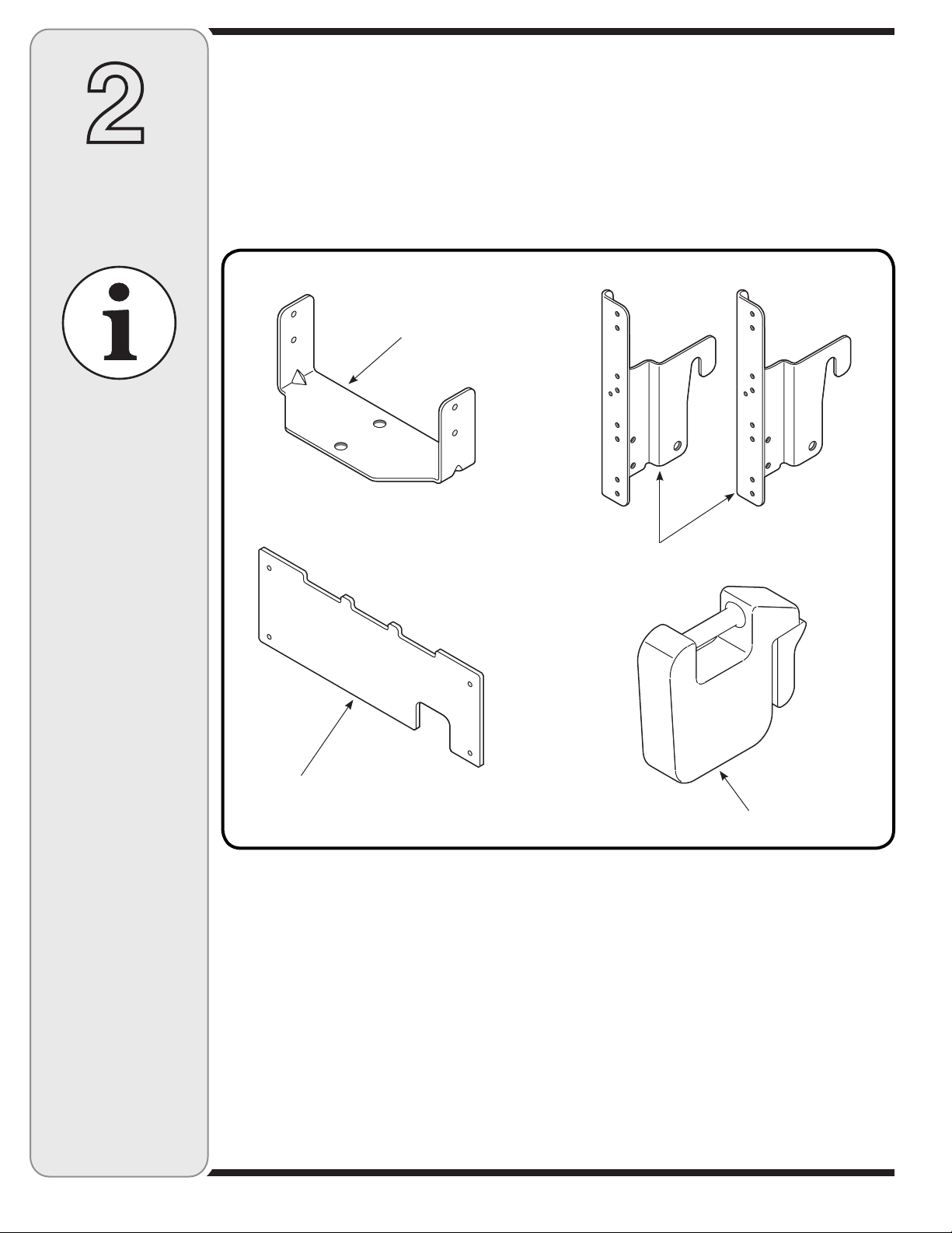
Before beginning installation, remove all parts from the carton to make sure everything is present. Carton
contents are listed below and shown in Fig. 2-1.
One Cross Support Bracket
One Rear Weight Plate
One Suitcase Weight
Cross Support Bracket
Two Catcher Support Brackets
Catcher Support Brackets
Rear Weight Plate
Suitcase Weight
Figure 2-1
4
Page 5
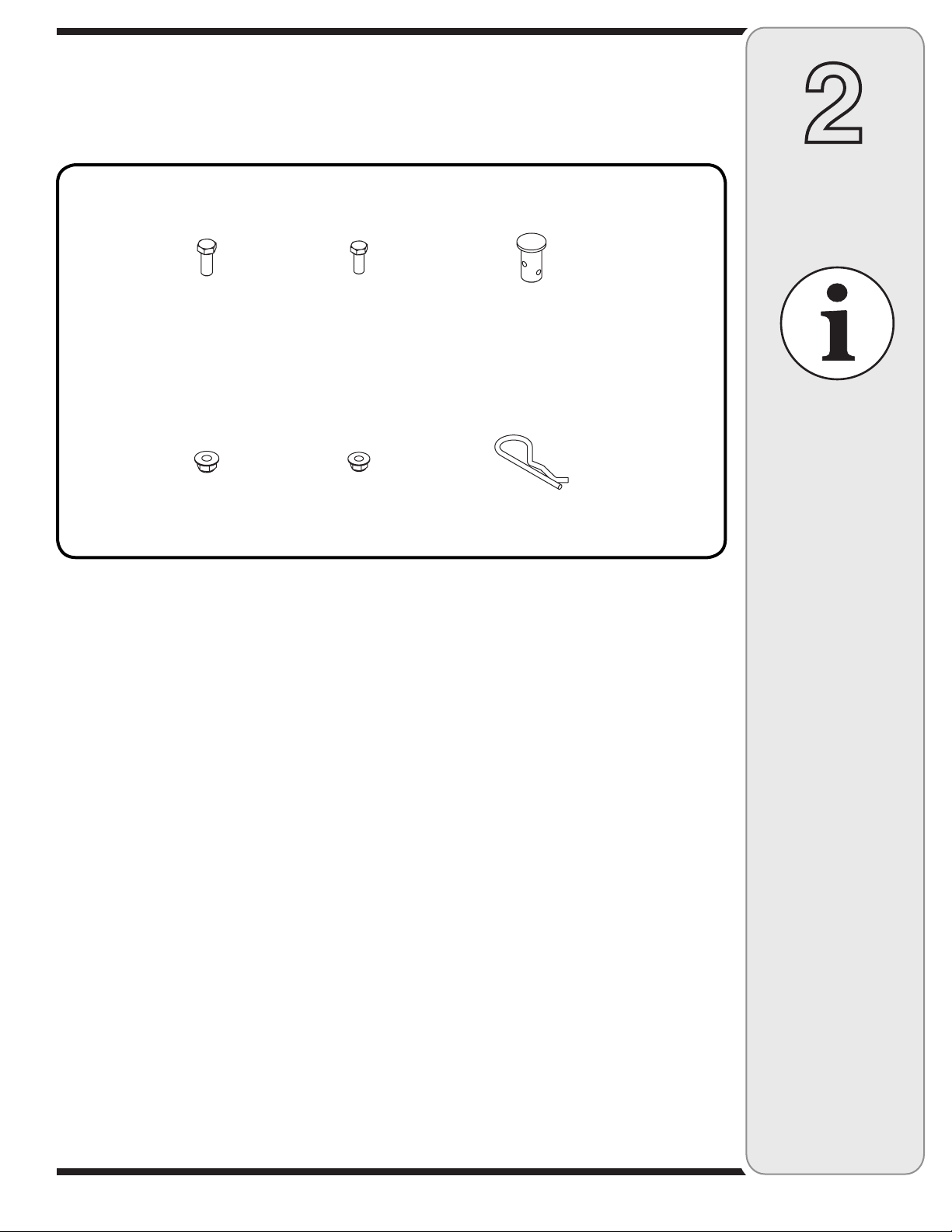
CONTENTS OF HARDWARE PACK
This weight kit is shipped with a hardware pack enclosed. Please check your hardware pack against the
illustration below.
2
Carton
A1
(4)
A2
(4)
NOTE: Each item has been identified above for ease of assembly, and the letter code assigned here is maintained in
assembly instructions.
B1
(4)
B2
(4)
Figure 2-2
C1
(1)
C2
(1)
(#) = Quantity
Contents
If you are missing any
parts, please do not
contact the retailer
where you purchased
this unit, call MTD
directly at 1-330-220-
4MTD or toll free at
1-800-800-7310.
NOTE:
Each item has
been identified in
above for ease of
assembly, and the
letter code assigned
here is maintained
in assembly
instructions.
(#) = Quantity
5
Page 6
Assembling & Attaching
3
Assembling
& Attaching
The Support
Assembly
IMPORTANT:
Before assembly,
place the tractor on
a firm, level surface,
disengage the PTO,
stop the tractor
engine and set the
parking brake.
NOTE:
If assembling this
weight kit for use on
an 800 Series hydrostatic garden tractor,
attach the weight
mounting plate with
the cutout on the left
hand side.
The Support Assembly
IMPORTANT: Before assembly, place the tractor on
a firm, level surface, disengage the PTO, stop the
tractor engine and set the parking brake.
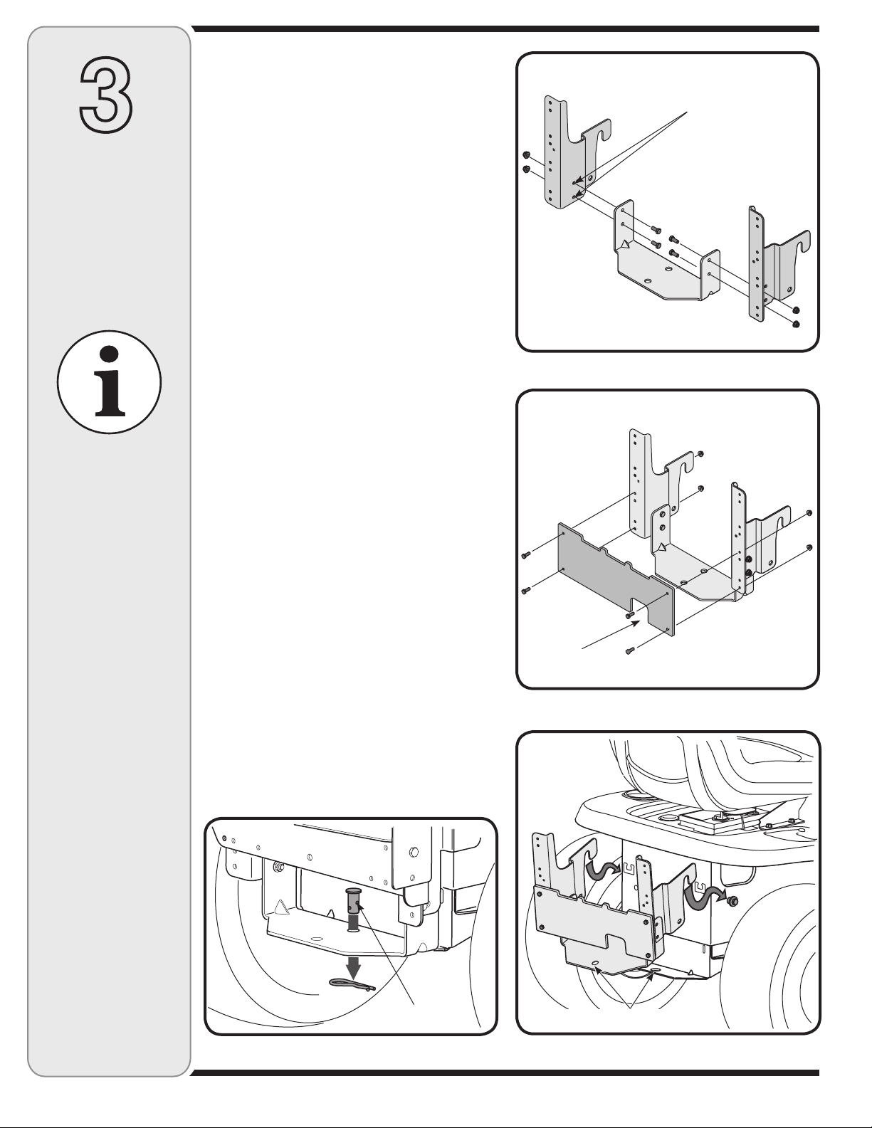
1. Secure the left and right hand catcher support brackets, to the cross support bracket using four 5/16-18
hex head screws (A1 in Figure 2-2) and four 5/16-18
flange lock nuts (A2 in Figure 2-2). Be sure to attach
the catcher supports using the two rear holes on the
catcher support brackets. Insert the hex screws from
the inside out. See Fig. 3-1 for reference.
2. Attach the weight mounting plate to the cross support
assembly with the cutout on the right hand side, as
seen in Fig. 3-2, using four 1/4-20 hex screws (B1
from Fig. 2-2) and secure with four 1/4-20 flange lock
nuts (B2 from Fig. 2-2).
NOTE: If assembling this weight kit for use on an 800
Series garden tractor, attach the weight mounting plate
with the cutout on the left hand side.
3. To attach the bracket assembly to the tractor, position the hooked ends of the bracket assembly over
the shoulder bolts on the tractor. Align the hole in
the cross support bracket with the hole on the hitch
plate. See Fig. 3-3.
4. Insert the clevis pin (C1 from Fig. 2-2) through the
aligned holes in both the bracket assembly and the
hitch plate and secure with the hairpin clip (C2 from
Fig. 2-2). Refer to Figure 3-4.
NOTE: There are two holes in the clevis pin. Be sure
to insert the hairpin clip in the upper hole to properly
secure the bracket assembly to the hitch plate.
5. Hang the suitcase weight on the rear weight plate,
refer to the cover image for reference. If only using
the included weight, hang it in the center of the rear
weight plate. If more weight is needed, up to two
more weights may be added to the left and right side
of the center weight.
Two Rear Holes
Figure 3-1
Cut-out
Figure 3-2
NOTE:
There are two holes
in the clevis pin.
Be sure to insert
the hairpin clip in
the upper hole to
properly secure the
bracket assembly to
the hitch plate.
Figure 3- 4
Upper Hole
Align These Two Holes
Figure 3-3
6
Page 7
4
10
Rear Mount
Weight Kit
Parts List
11
1
8
2
2
7
9
3
1
For parts and/or
accessories
please call
4
1-800-800-7310
or log onto
www.mtdproducts.com
6
5
REF
NO.
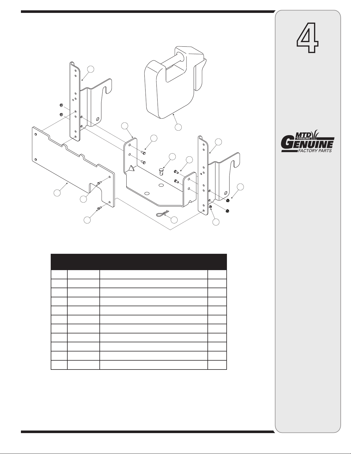
1 710-3008 Hex Head Screw, 5/16-18 x .75” 4
2 710-3015 Hex Head Screw, 1/4-20 x .75 4
3 711-0309A Clevis Pin, .62 Dia. 1
4 712-04063 Flange Lock Nut, 5 /16-18 4
5 712-04064 Flange Lock Nut, 1/4-20 4
6 714-0117 Internal Cotter Pin, .148 x 3.00 1
7 759-3389 Suitcase Weight, 45 lbs. 1
8 783-05244 Rear Weight Plate 1
9 783-0673B Catcher Support Bracket, Right Hand 1
10 783-0764B Catcher Support Bracket, Left Hand 1
11 783-0765 Cross Support Bracket 1
PART
NUMBER
DESCRIPTION Qty.
7
Page 8

MTD LLC, P.O. BOX 361131 CLEVELAND, OHIO 44136-0019
 Loading...