

Mtd OEM-190-182 owners guide
Operator’s Manual
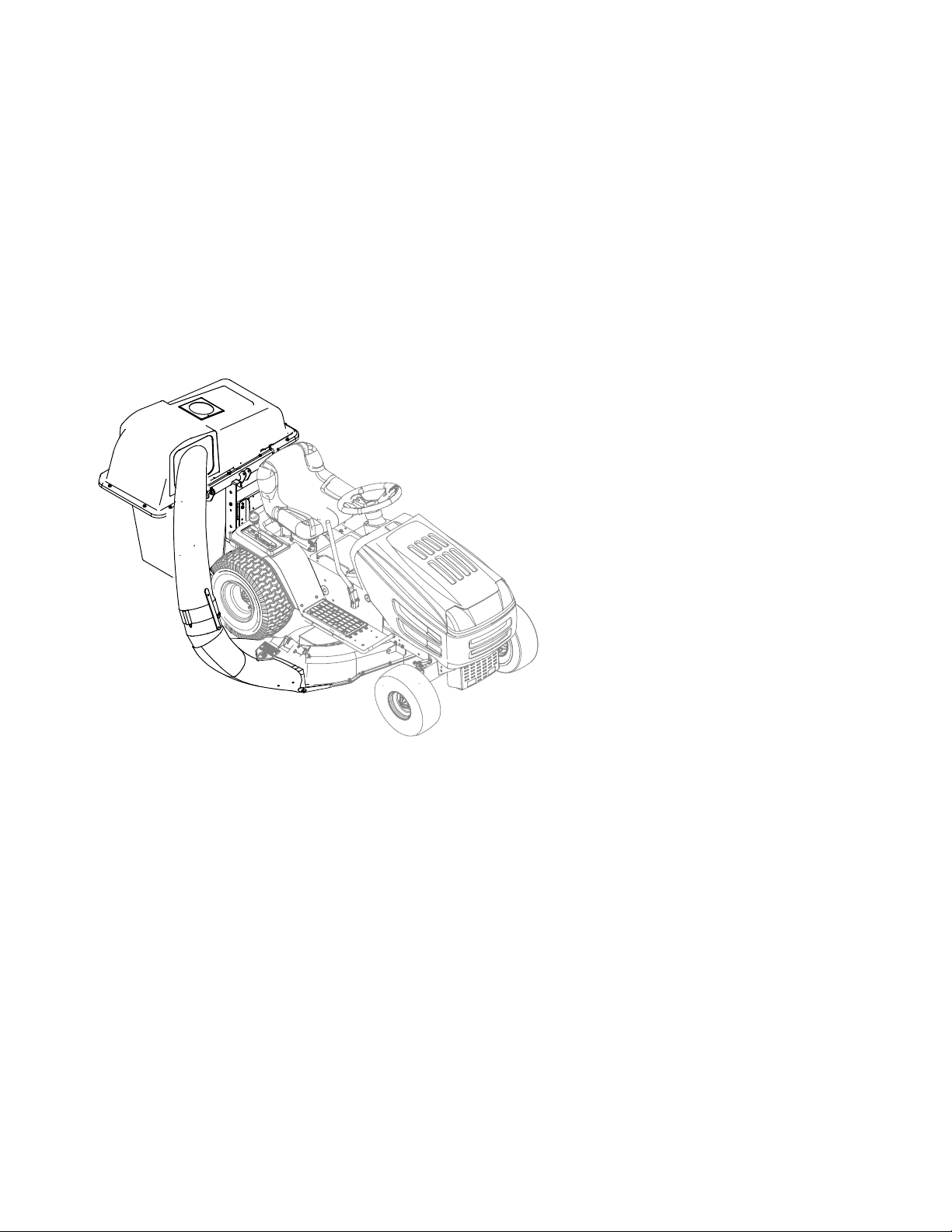
Twin Rear Bagger Kit
Models OEM-190-180
OEM-190-182
&
IMPORTANT: Read safety rules and instructions carefully before operating equipment.
Warning: This unit is equipped with an internal combustion engine and should not be used on or near any unimproved forest-
covered, brush-covered or grass-covered land unless the engine’s exhaust system is equipped with a spark arrester meeting
applicable local or state laws (if any). If a spark arrester is used, it should be maintained in effective working order by the operator.
In the State of California the above is required by law (Section 4442 of the California Public Resources Code). Other states may have
similar laws. Federal laws apply on federal lands. A spark arrester for the muffler is available through your nearest engine authorized
service dealer or contact the service department, P.O. Box 361131 Cleveland, Ohio 44136-0019.
MTD LLC, P.O. BOX 361131 CLEVELAND, OHIO 44136-0019
PRINTED IN U.S.A.
FORM NO.
770-10253D.fm
(11/2003)
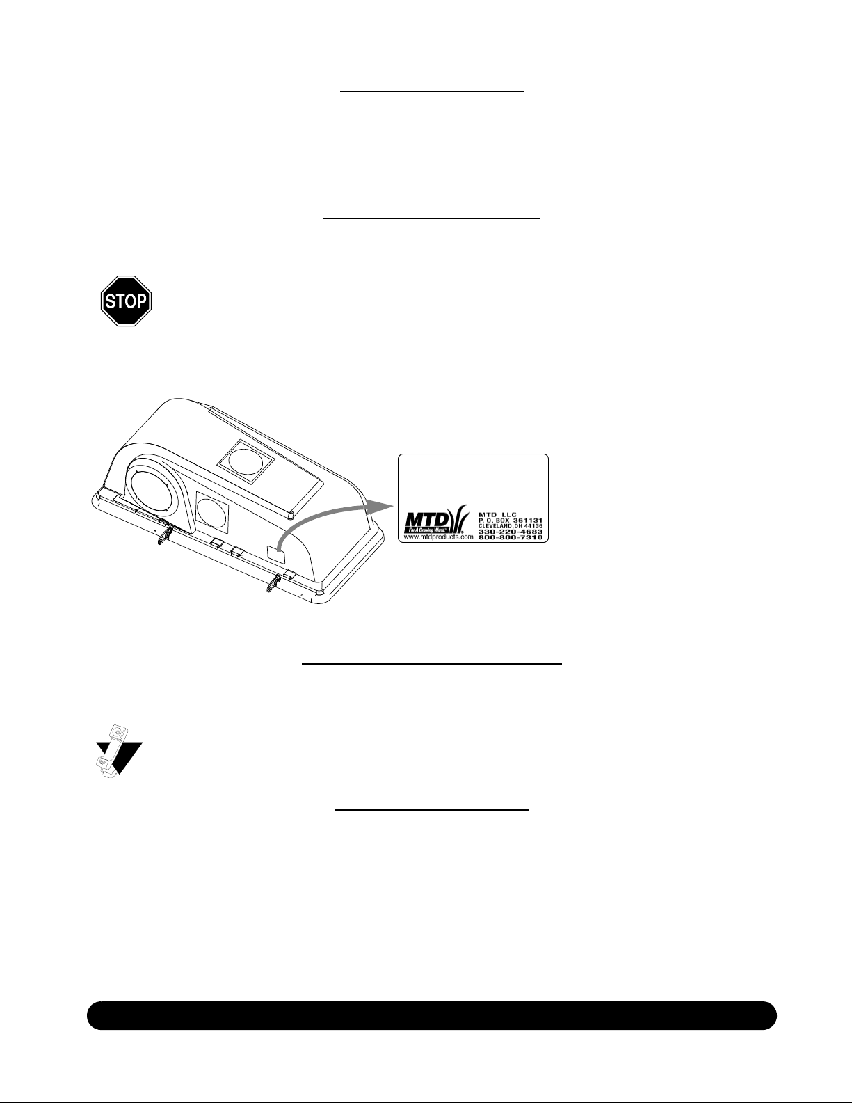
TABLE OF CONTENTS
Content Page
Loose Parts........................................................................................................3
Assembly & Operation .......................................................................................4
Parts List............................................................................................................10
FINDING MODEL NUMBER
This Operator’s Manual is an important part of your new lawn tractor. It will help you assemble, prepare and
maintain the unit for best performance. Please read and understand what it says.
Before you start assembling your new equipment, please locate the model pla te on the
equipment and copy the information from it in the space provided below. The information on the
model plate is very important if you need help from our Customer Support Department or an
authorized dealer.
• You can locate the model number in the front, left portion of the plastic grass catcher cover. A sample model
plate is explained below. For future reference, please copy model number and serial number of the tractor
accessoryin the space below.
Copy the model number here:
Copy the serial number here:
CALLING CUSTOMER SUPPORT
If you have difficulty assembling this product or have any questions regarding the controls, operatio n or
maintenance of this unit, please call the Customer Support Depa rtment.
Call 1- (330) 220- 4MTD (4683) or 1- (80 0)-800-7310 to reach a Customer Support representative.
Please have your unit’s model number and serial number ready when you call. See previous section
to locate this information. You will be asked to enter the serial number in order to process your call.
YOUR RESPONSIBILITY
Restrict the use of this accessory and the tractor to persons who read, under stand and follow the warnings and
instructions in this manual and on the machine.
NOTE: Model 180 and Model 182 Twin Rear Bagger Kits are grass collection systems designed for use on 600
Series Lawn Tractors equipped with either a 3 8- o r 42-i nch cutting de ck (Model 180) or a 800 Se ries Tractor wit h
46-inch cutting deck (Model 182) only.These will NOT mount, nor operate safely or properly on any other tractor
regardless of the tractor’s compatibility with similar accessories.
For more details about your unit, visit our website at www.mtdproducts.com
2
SECTION 1: LOOSE PARTS
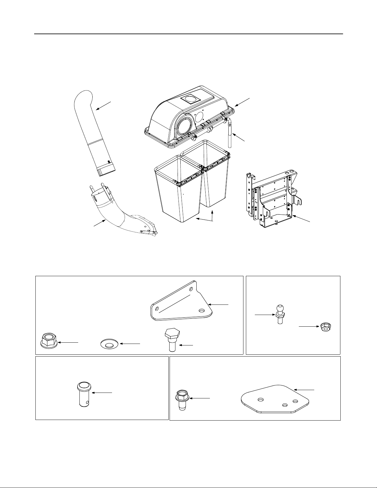
The grass catcher kit is shipped with following loose parts in the carton. Please remove all loose parts, including the
hardware pack, from the carton before discarding it . Compare with Figure 1 to check that all part s were included.
Note that the kit and the hardware pack contain extra items wh ich are not used on your unit.
Chute Tube
Discharge Chute
Assembly
Contents of Hardware Pack
Figure 1
Bag Assemblies
Grasscatcher Cover
Assembly
Support Tube
(attached to cover)
Mounting
Bracket
For all Model Series 600 tractors only
A
D
NOTE: Each item has been identified in Figure 2 for ease of assembly, and the letter code assigned here is
maintained in assembly instructions. However, the hardware pack contains more than one of some items.
B
For all Model Series 800 tractors only For older Model Series 600 tractors only
(Available in Bagger Kit 190-182 only)
Figure 2
C
E
For decks with grasscatcher
pin not pre-installed
F1
G
H
F2
3
SECTION 2: ASSEMBLY & OPERATION
NOTE: References to LEF T, RIGHT , FRONT and
REAR of the tractor are from the operator’s posit ion.
• Before assembly, place the tractor on a firm, level
surface, disengage the PTO, stop the tractor
engine and set the parking brake.
Tractor Model Series 660 through 690
Assembling Support Brackets
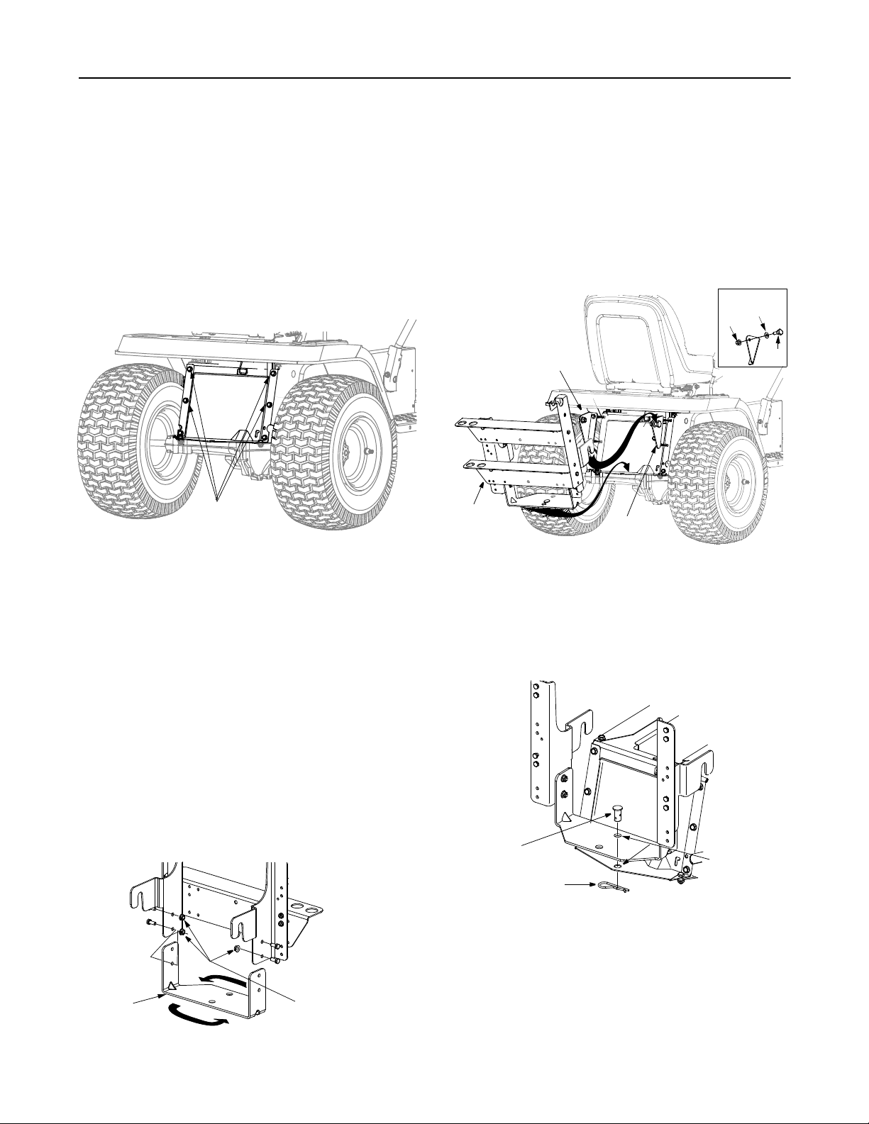
• Remove the top four self-tapping screws from the
rear of the lawn tractor. See Figure 3.
Remove these
screws
Figure 3
• Place the right hand grass catcher support bracket
(F1 from Figure 2) in position as shown in Figure 5.
• Secure the support bracket to the tractor fram e with
two self-tapping screws earlier removed. Refer to
Figure 3. Repeat on the other side.
NOTE: If the grass collection system is removed for any
reason, it is not necessary to remove the support
brackets from the tractor.
• Re-insert the four bolts through mounting bracket
and hitchplate frame and secure with nuts removed
earlier. Refer to Figure 4.
• Remove the hairpin clip and clevis pin from the
hitch plate. Save the hardware.
• Position the hooked ends of the mounting bracke t
assembly to the outside of the support bracket an d
over the shoulder bolts on both sides as shown in
Figure 5.
Bell
Washer
Nut
Bolt
Mounting
Bracket
Assembly
Catcher
Support
Bracket
Catcher
Support
Bracket
Figure 5
• Align the hole at the lower end of the mounting
bracket assembly to the hole on the hitch plate and
insert the clevis pin, mentioned earlier, thr ough
these two holes. Secure the clevis pin with the
hairpin clip. See Figure 6.
• Insert a shoulder bolt (C in Figure 2) t hrough a bell
washer,(B in Figure 2) and insert the bolt through
the hole on the support bracket. Secure with a nut
(A in Figure 2). See Figure 5 inset for details.
Repeat on other side.
• Remove two nuts on each side of the mounting
bracket holding the hitch plate. Rotate the hitch
plate 180° from its original position. See Figure 4.
Hitch
Plate
Remove these nuts
(Only 3 shown here)
Figure 4
Clevis
Pin
Hairpin Clip
Align these
holes
Figure 6
NOTE: For some tractor models, this clevis pin is too
large. Use a smaller clevis pin (D in Figure 2) in its
place with the same hairpin clip.
• Slide the support tube, attached to the grass bag
cover, down through the hole on the left side of the
mounting brackets. See Figure 7. Make sure the
tube passes through both holes of the bracket.
4
 Loading...