

MSI MS-7082 User Manual
i
G52-M7082X3
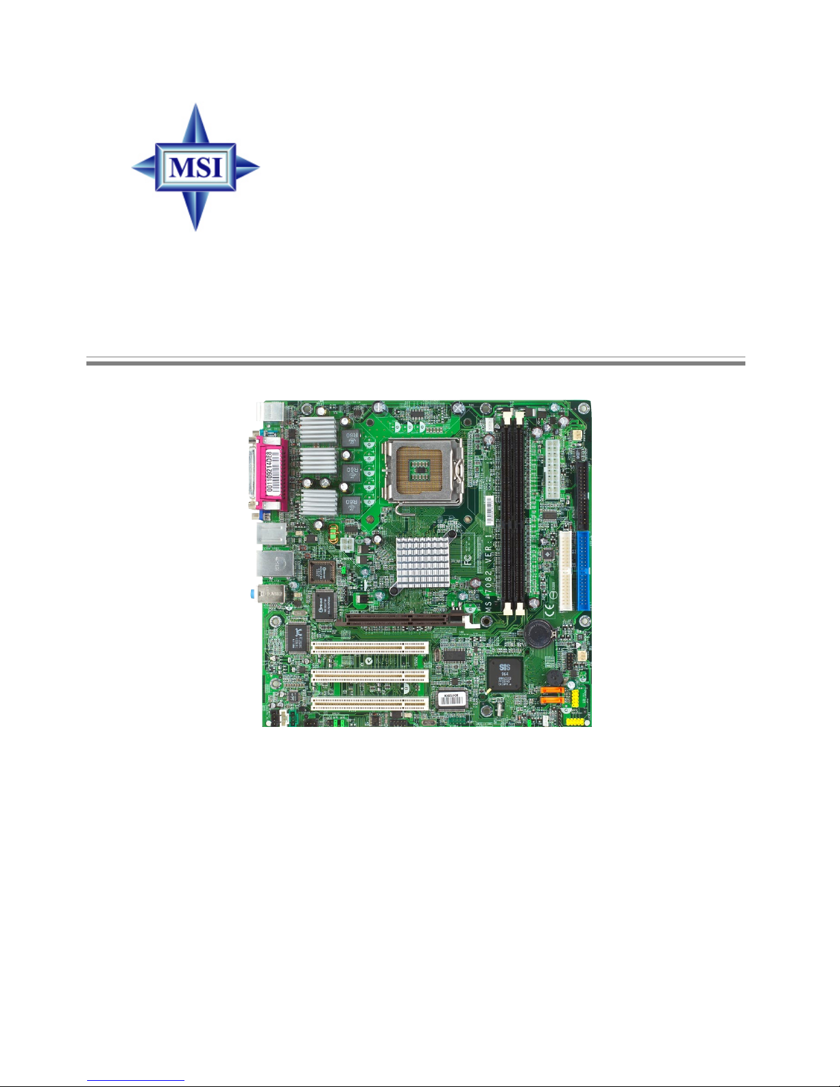
661FM3 Series
MS-7082 (v1.X) Micro ATX Mainboard
ii
Manual Rev: 1.1
Release Date: September 2004
FCC-B Radio Frequency Interference Statement
This equipment has been tested and found to comply with the limits for a class
B digital device, pursuant to part 15 of the FCC rules. These limits are designed
to provide reasonable protection against harmful interference when the equipment is operated in a commercial environment. This equipment generates, uses
and can radiate radio frequency energy and, if not installed and used in accordance with the instruction manual, may cause harmful interference to radio
communications. Operation of this equipment in a residential area is likely to
cause harmful interference, in which case the user will be required to correct
the interference at his own expense.
Notice 1
The changes or modifications not expressly approved by the party responsible for compliance could void the user’s authority to operate the equipment.
Notice 2
Shielded interface cables and A.C. power cord, if any, must be used in order to
comply with the emission limits.
VOIR LA NOTICE D’INSTALLATION AVANT DE RACCORDER AU
RESEAU.
Micro-Star International
MS-7082

iii
Copyright Notice
The material in this document is the intellectual property of MICRO-STAR
INTERNATIONAL. We take every care in the preparation of this document,
but no guarantee is given as to the correctness of its contents. Our products
are under continual improvement and we reserve the right to make changes
without notice.
Trademarks
All trademarks are the properties of their respective owners.
AMD, Athlon™, Athlon™ XP, Thoroughbred™, and Duron™ are registered
trademarks of AMD Corporation.
Intel® and Pentium® are registered trademarks of Intel Corporation.
PS/2 and OS®/2 are registered trademarks of International Business Machines
Corporation.
Microsoft is a registered trademark of Microsoft Corporation. Windows® 98/
2000/NT/XP are registered trademarks of Microsoft Corporation.
NVIDIA, the NVIDIA logo, DualNet, and nForce are registered trademarks or
trademarks of NVIDIA Corporation in the United States and/or other countries.
Netware® is a registered trademark of Novell, Inc.
Award® is a registered trademark of Phoenix Technologies Ltd.
AMI® is a registered trademark of American Megatrends Inc.
Kensington and MicroSaver are registered trademarks of the Kensington Technology Group.
PCMCIA and CardBus are registered trademarks of the Personal Computer
Memory Card International Association.
Revision History
Revision Revision History Date
V1.0 First release for PCB 1.x with August 2004
chipsets SiS661FX / 648FX
& SiS964 / 964L
V1.1 Manual cover updates September 2004

iv
1. Always read the safety instructions carefully.
2. Keep this User’s Manual for future reference.
3. Keep this equipment away from humidity.
4. Lay this equipment on a reliable flat surface before setting it up.
5. The openings on the enclosure are for air convection hence protects the
equipment from overheating. Do not cover the openings.
6. Make sure the voltage of the power source and adjust properly 110/220V
before connecting the equipment to the power inlet.
7. Place the power cord such a way that people can not step on it. Do not
place anything over the power cord.
8. Always Unplug the Power Cord before inserting any add-on card or module.
9. All cautions and warnings on the equipment should be noted.
10. Never pour any liquid into the opening that could damage or cause electrical
shock.
11. If any of the following situations arises, get the equipment checked by a
service personnel:
h The power cord or plug is damaged.
h Liquid has penetrated into the equipment.
h The equipment has been exposed to moisture.
h The equipment has not work well or you can not get it work according
to User’s Manual.
h The equipment has dropped and damaged.
h The equipment has obvious sign of breakage.
12. Do not leave this equipment in an environment unconditioned, storage
temperature above 600 C (1400F), it may damage the equipment.
Safety Instructions
CAUTION: Danger of explosion if battery is incorrectly replaced.
Replace only with the same or equivalent type recommended by the
manufacturer.

v
CONTENTS
FCC-B Radio Frequency Interference Statement ........................................... ii
Copyright Notice .......................................................................................... iii
Revision History ........................................................................................... iii
Safety Instructions ....................................................................................... iv
Chapter 1. Getting Started ........................................................................ 1-1
Mainboard Specifications .................................................................... 1-2
Mainboard Layout ............................................................................... 1-4
Chapter 2. Hardware Setup ....................................................................... 2-1
Quick Components Guide .................................................................... 2-2
Central Processing Unit: CPU .............................................................. 2-3
Memory ................................................................................................ 2-7
Introduction to DDR SDRAM ....................................................... 2-7
DDR Module Combination ............................................................ 2-8
Installing DDR Modules ............................................................... 2-8
Power Supply ....................................................................................... 2-9
ATX 20-Pin Power Connector: CONN1 ......................................... 2-9
ATX 12V Power Connector: JPW2000 ........................................... 2-9
Back Panel .......................................................................................... 2-10
Mouse Connector ....................................................................... 2-10
Keyboard Connector ................................................................... 2-11
USB Connectors .......................................................................... 2-11
Serial Port Connector ................................................................... 2-12
VGA Connector ........................................................................... 2-12
IEEE 1394 Port (Optional) ............................................................ 2-12
RJ-45 LAN Jack ........................................................................... 2-13
Audio Port Connectors ............................................................... 2-14
Parallel Port Connector: LPT1 ...................................................... 2-15
Connectors ............................................................................................... 2-15
Floppy Disk Drive Connector: FDD1 ........................................... 2-16

vi
Fan Power Connectors: CPUFAN2 & POWFAN1& CHSFAN1... 2-16
Hard Disk Connectors: IDE1 & IDE2 ........................................... 2-17
Serial ATA HDD Connectors: SATA1 & SATA2 ......................... 2-18
IEEE 1394 Connector: J1394_1 (Optional) .................................... 2-19
Serial Port Connector: JCOM1 ..................................................... 2-19
Front Panel Connectors: JFP1 ..................................................... 2-20
Aux Line-In Connector: AUX_IN1 .............................................. 2-20
CD-In Connector: CD_IN1 .......................................................... 2-21
Front Panel Audio Connector: JAUD1 ........................................ 2-21
Front USB Connectors: JUSB1 & JUSB2 ..................................... 2-22
SPDIF Connector: JSP1 ............................................................... 2-22
IrDA Infrared Modele Header: IR1 .............................................. 2-23
Wake On LAN Connector: JWOL ............................................... 2-23
Wake Up On Modem Connector: JMR1 ...................................... 2-23
Jumpers .............................................................................................. 2-22
Clear CMOS Jumper: JBAT1 ........................................................ 2-24
BIOS Flash Jumper: BIOS_WP1 .................................................. 2-24
Slots ................................................................................................... 2-25
AGP (Accelerated Graphics Port) Slot ......................................... 2-25
PCI (Peripheral Component Interconnect) Slots .......................... 2-25
PCI Interrupt Request Routing .................................................... 2-25

1-1
Hardware Setup
Chapter 1. Getting
Started
Thank you for purchasing 661FM3 Series (MS-7082 v1.X) Micro ATX
mainboard. The 661FM3 Series (MS-7082 v1.X) is based on SiS
®
661FX / 648FX & SiS® 964 / 964L chipsets for optimal system
efficiency. Designed to fit the advanced Intel® Pentium 4/Celeron
DTM (LGA775) processor, the 661FM3 Series (MS-7082 v1.X) delivers
a high performance and professional desktop platform solution.
Getting Started

1-2
MS-7082 Micro ATX Mainboard
Mainboard Specifications
CPU
h Supports Intel® Pentium 4 / Celeron-D in the 775-land package
h Supports 533MHz, 800MHz FSB
h Supports 2004 Performance FMB CPU VR Design
h Supports 3/4 pin CPU Fan Pin-Header with Fan Speed Control
(For the latest information about CPU, please visit http://www.msi.com.tw/program/
products/mainboard/mbd/pro_mbd_cpu_support.php )
Chipset
h SiS ® 661FX / 648FX Chipset
- Integrated graphic controller (661FX only)
- Support DDR333/400 SDRAM
h SiS® 964 / 964L Chipset
- High Definition Audio interface
- 8 USB 2.0/1.1 ports
- 2 channel Ultra ATA66/100/133 Bus Master IDE controller
- 2 serial ATA Host Controllers (964 only)
Main Memory
h Supports 64-bit wide DDR
h Available bandwidth up to 3.2GB/s (DDR 400)
h Supports 128Mb, 256Mb or 512Mb DDR technologies
(For the updated supporting memory modules, please visit http://www.msi.com.tw/
program/products/mainboard/mbd/pro_mbd_trp_list.php )
Slots
h One AGP Slot
h Three PCI Slots (32-bit v2.3 Master PCI bus, supports 3.3/5v PCI bus interface)
On-Board IDE
h An IDE controller on the 964/964L chipset provides IDE HDD/CD-ROM with PIO,
Bus Master and Ultra DMA66/100/133 operation modes.
h Support 2 Serial ATA 150 ports.
On-Board Peripherals
h On-Board Peripherals include:
- 1 floppy port supports 1 FDD with 360K, 720K, 1.2M, 1.44M and 2.88Mbytes.
- 2 serial port, Com1 on Rear IO, Com2 via pin header(IO bracket is optional)
- 1 parallel port supports SPP/EPP/ECP mode
- 8 USB 2.0/1.1 ports (Rear * 4 / Front * 4)
- 1 Line-In/Line-Out/Mic
- 1 RJ45 connector (Optional)
- 2 IEEE1394 connectors (Rear x1 and Front x 1)(Optional)
- 1 VGA port (661FX only)

1-3
Hardware Setup
Audio
h High Definition link controller integrated in 964/964L
h 6 channels (HDA) audio codec
- Meet PC2001 audio performance requirement
- Can support SPDIF Out via bracket only
On-Board LAN (Optional)
h RealtekR 8100C / 81 10S (optional)
- Integrated Fast Ethernet MAC and PHY in one chip.
- Supports 10Mb/s, 100Mb/s and 1000Mb/s (1000Mb/s for 8110S
only).
- Compliance with PCI 2.2.
- Supports ACPI Power Management
1394 (optional)
h Supports up to 2 * 1394 ports, one 6-pin 1394 connector on rear I/O, the other is
supported by onboard pinheader. Transfer rate is up
to 400Mbps.
h Controlled by VIA 6307 chipset.
BIOS
h 4MB Award BIOS
h Provides DMI 2.0, WFM 2.0, WOL, WOR and SMBus for system management.
Dimension
h Micro-ATX Form Factor: 24.4 cm (L) x 24.4 cm (W)
Mounting
h 8 mounting holes
1-4
MS-7082 Micro ATX Mainboard
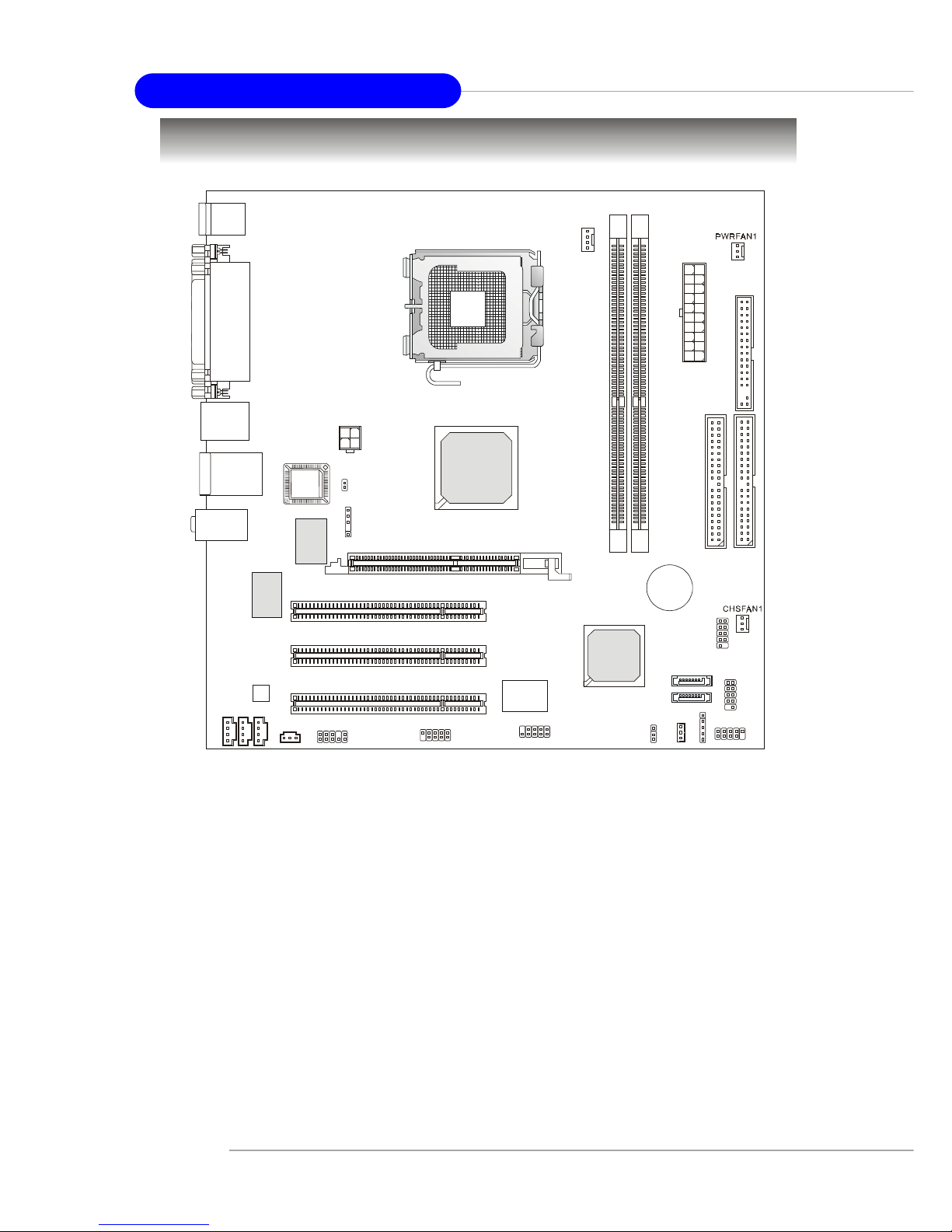
Mainboard Layout
MS-7082 v1.X Micro ATX Mainboard
C
P
U
F
A
N
2
JPW2000
SATA1
SATA2
C
D
_
I
N
1
T:
M:
B:
Line-In
Line-Out
Mic
Winbond
W83687THF
SiS
964/964L
SiS
661FX/648FX
BATT
+
D
I
M
M
1
D
I
M
M
2
PCI 3
PCI 2
PCI 1
I
D
E
1
F
D
D
1
I
D
E
2
JFP1
JUSB2
JUSB1
JBAT1
JCOM1
J1394_1(Optional)
VIA
VT6307
JAUD1
JSP1
IR1
BIOS_WP1
Top : mouse
Bottom: keyboard
T:IEEE 1394 (Optional)
B:USB ports
C
O
N
N
1
BIOS
T: LA N jack
B: USB ports
(Optional)
Top : Para llel Port
Bottom:
COM 1
VGA Port (661FX only)
RTL8100C/
8110S
Codec
AGP Slot
JWOL
JMR1
AUX_IN1
M
D
M
_
I
N
1

2-1
Hardware Setup
Chapter 2. Hardware
Setup
This chapter tells you how to install the CPU, memory modules, and expansion
cards, as well as how to setup the jumpers on the mainboard. It also provides the
instructions on connecting the peripheral devices, such as the mouse, keyboard,
etc.
While doing the installation, be careful in holding the components and follow the
installation procedures.
Hardware Setup
 Loading...