

MSI 865PE Neo3-F, 865PE Neo3-FS, 865PE Neo3-V, MS-6728, 865PE/G Neo3 User Manual
i
865PE/G Neo3
G52-M6728XX
MS-6728 (v3.X) A TX Mainboard
ii
Manual Rev: 3.1
Release Date: October 2004
FCC-B Radio Frequency Interference Statement
This equipment has been tested and found to comply with the limits for a class B
digital device, pursuant to part 15 of the FCC rules. These limits are designed to
provide reasonable protection against harmful interference when the equipment is
operated in a commercial environment. This equipment generates, uses and can
radiate radio frequency energy and, if not installed and used in accordance with the
instruction manual, may cause harmful interference to radio communications. Operation
of this equipment in a residential area is likely to cause harmful interference, in which
case the user will be required to correct the interference at his own expense.
Notice 1
The changes or modifications not expressly approved by the party responsible for
compliance could void the user’s authority to operate the equipment.
Notice 2
Shielded interface cables and A.C. power cord, if any, must be used in order to
comply with the emission limits.
VOIR LA NOTICE D’INST ALLATION AVANT DE RACCORDER AU RESEAU.
Micro-Star International
MS-6728
This device complies with Part 15 of the FCC Rules. Operation is subject to the
following two conditions:
(1) this device may not cause harmful interference, and
(2) this device must accept any interference received, including interference that
may cause undesired operation

iii
Copyright Notice
The material in this document is the intellectual property of MICRO-STAR
INTERNATIONAL. We take every care in the preparation of this document, but no
guarantee is given as to the correctness of its contents. Our products are under
continual improvement and we reserve the right to make changes without notice.
Trademarks
All trademarks are the properties of their respective owners.
AMD, Athlon™, Athlon™ XP, Thoroughbred™, and Duron™ are registered
trademarks of AMD Corporation.
Intel® and Pentium® are registered trademarks of Intel Corporation.
PS/2 and OS®/2 are registered trademarks of International Business Machines
Corporation.
Microsoft is a registered trademark of Microsoft Corporation. Windows® 98/2000/NT/
XP are registered trademarks of Microsoft Corporation.
NVIDIA, the NVIDIA logo, DualNet, and nForce are registered trademarks or trademarks of NVIDIA Corporation in the United States and/or other countries.
Netware® is a registered trademark of Novell, Inc.
Award® is a registered trademark of Phoenix Technologies Ltd.
AMI® is a registered trademark of American Megatrends Inc.
Kensington and MicroSaver are registered trademarks of the Kensington Technology
Group.
PCMCIA and CardBus are registered trademarks of the Personal Computer Memory
Card International Association.
Revision History
Revision Revision History Date
V3.0 First release of PCB 3.0 with chipsets August 2004
Intel® 865PE/G & Intel® ICH5/ICH5R
V3.1 First release for PCB 3.0 October 2004
English/French/German version

iv
1. Always read the safety instructions carefully.
2. Keep this User’s Manual for future reference.
3. Keep this equipment away from humidity.
4. Lay this equipment on a reliable flat surface before setting it up.
5. The openings on the enclosure are for air convection hence protects the equipment from overheating. Do not cover the openings.
6. Make sure the voltage of the power source and adjust properly 110/220V before connecting the equipment to the power inlet.
7. Place the power cord such a way that people can not step on it. Do not place
anything over the power cord.
8. Always Unplug the Power Cord before inserting any add-on card or module.
9. All cautions and warnings on the equipment should be noted.
10. Never pour any liquid into the opening that could damage or cause electrical
shock.
11. If any of the following situations arises, get the equipment checked by a service
personnel:
h The power cord or plug is damaged.
h Liquid has penetrated into the equipment.
h The equipment has been exposed to moisture.
h The equipment has not work well or you can not get it work according to
User’s Manual.
h The equipment has dropped and damaged.
h The equipment has obvious sign of breakage.
12. Do not leave this equipment in an environment unconditioned, storage
temperature above 600 C (1400F), it may damage the equipment.
Safety Instructions
CAUTION: Danger of explosion if battery is incorrectly replaced.
Replace only with the same or equivalent type recommended by the
manufacturer.
Technical Support
If a problem arises with your system and no solution can be obtained from the user’s
manual, please contact your place of purchase or local distributor. Alternatively,
please try the following help resources for further guidance.
h Visit the MSI homepage & FAQ site for technical guide, BIOS updates, driver
updates, and other information: http://www.msi.com.tw & http://www.msi.
com.tw/program/service/faq/faq/esc_faq_list.php
h Contact our technical staff at: support@msi.com.tw

v
CONTENTS
FCC-B Radio Frequency Interference Statement ........................................................ ii
Copyright Notice ........................................................................................................... iii
Revision History............................................................................................................ iii
Safety Instructions ...................................................................................................... iv
Technical Support ........................................................................................................ iv
English version .................................................................................................. E-1-1
1. Getting Started ............................................................................................ E-1-3
2. Hardware Setup.......................................................................................... E-2-1
3. BIOS Setup .................................................................................................. E-3-1
4. Introduction to DigiCell................................................................................. E-4-1
French version .......................................................................................................F-1
German version .................................................................................................... G-1

E-1-1
Getting Started
865PE/G Neo3
User’s Guide
English

E-1-2
MS-6728 ATX Mainboard

E-1-3
Getting Started
Chapter 1. Getting
Started
Getting Started
Thank you for choosing the 865PE/G Neo3 (MS-6728) v3.X ATX
mainboard. The 865PE/G Neo3 is based on Intel® 865PE/G &
ICH5/5R chipsets for optimal system efficiency. Designed to fit
the advanced Intel® Pentium 4 Prescott LGA775 processor,
the 865PE/G Neo3 delivers a high performance and professional
desktop platform solution.

E-1-4
MS-6728 ATX Mainboard
Mainboard Specifications
CPU
h Supports Intel® Pentium 4 Prescott LGA775 processors in LGA775 package.
h Supports up to Pentium 4 3XX, 5XX, 6XX & P4EE (Intel Pentium 4 Processor with
HT Technology Extreme Edition) sequence processor or higher speed.
(For the latest information about CPU, please visit http://www.msi.com.tw/program/
products/mainboard/mbd/pro_mbd_cpu_support.php)
Chipset
h Intel® 865PE/G chipset
- Supports FSB 800/533MHz.
- Supports AGP 8X interface.
- Supports DDR 400/333/266 memory interface.
- Integrated graphics controller (for 865G only).
h Intel® ICH5/ICH5R chipset
- Hi-Speed USB (USB2.0) controller, 480Mb/sec, 8 ports.
- 2 Serial ATA/150 ports.
- 2 channel Ultra ATA 100 bus Master IDE controller.
- PCI Master v2.3, I/O APIC.
- Supports both ACPI and legacy APM power management.
- Serial ATA/150 RAID 0 and RAID 1 (Optional).
Main Memory
h Supports four unbuffered DIMM of 2.5 Volt DDR SDRAM.
hh
hh
h Supports up to 4GB memory size without ECC.
hh
hh
h Supports Dual channel DDR266/333/400 MHz.
Slots
h One AGP slot supports 8x/4x.
h Five 32-bit v2.3 Master PCI bus slots (support 3.3v/5v PCI bus interface).
On-Board IDE
h Dual Ultra DMA 66/100 IDE controllers integrated in ICH5/ICH5R.
- Supports PIO, Bus Master operation modes.
- Can connect up to four Ultra ATA drives.
h Serial ATA/150 controller integrated in ICH5/ICH5R.
- Up to 150MB/sec transfer speeds.
- Can connect up to two Serial ATA drives.
- Supports SATA RAID 0/RAID 1 (Optional).

E-1-5
Getting Started
On-Board Peripherals
h On-Board Peripherals include:
- 1 floppy port supports 1 FDD with 360K, 720K, 1.2M, 1.44M and 2.88Mbytes
- 1 serial port COMA
- 1 VGA port (for 865G only)
- 1 parallel port supports SPP/EPP/ECP mode
- 8 USB 2.0 ports (Rear * 4/ Front * 4)
- 1 Line-In / Line-Out / Mic-In / Real Speaker Out / Center-Subwoofer Speaker Out
/ SPDIF Out-Optical audio port
- 1 RJ45 LAN jack (Optional)
- 2 IEEE 1394 pinheaders (Optional)
Audio
h AC97 link controller integrated in Intel® ICH5/ICH5R chipset.
h 8-channel audio codec Realtek ALC850.
- Compliance with AC97 v2.3 Spec.
- Meet PC2001 audio performance requirement.
LAN
h Realtek® 8100C / 8110S (Optional)
- Integrated Fast Ethernet MAC and PHY in one chip.
- Supports 10Mb/s, 100Mb/s and 1000Mb/s (1000Mb/s for 8110S only).
- Compliance with PCI 2.2.
- Supports ACPI Power Management.
BIOS
h The mainboard BIOS provides “Plug & Play” BIOS which detects the peripheral
devices and expansion cards of the board automatically.
h The mainboard provides a Desktop Management Interface (DMI) function which
records your mainboard specifications.
Dimension
h ATX Form Factor: 30.5 cm (L) x 24.5 cm (W).
Mounting
h 9 mounting holes.
E-1-6
MS-6728 ATX Mainboard
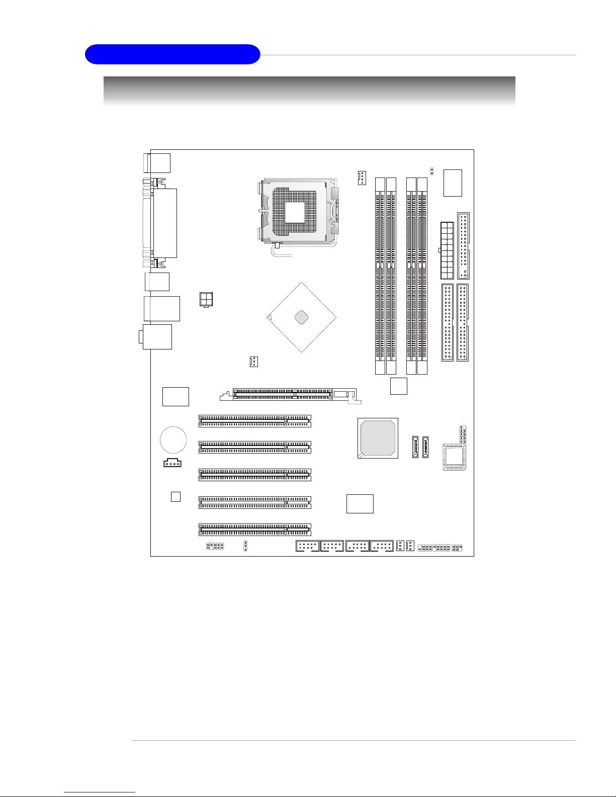
Mainboard Layout
865PE/G Neo3 (MS-6728) v3.X ATX Mainboard
ICH5/
ICH5R
D
I
M
M
1
D
I
M
M
3
D
I
M
M
2
D
I
M
M
4
JAUD1
J1394_1 J1394_2
JUSB1
A
T
X
P
o
w
e
r
S
u
p
p
l
y
CPUFAN1
NBFAN1
S
F
A
N
1
S
F
A
N
2
SATA1
SATA2
JFP1JFP2
JIR1
Codec
Winbond
W83627HF
Realtek
8100C/8110S
(Optional)
VIA
VT6307
BIOS
PCI Slot 5
PCI Slot 4
PCI Slot 3
PCI Slot 2
PCI Slot 1
I
D
E
1
I
D
E
2
JPW1
Top : mouse
Bottom: ke yboar d
T: LAN jack
(Optional)
B: USB ports
JCD1
F
D
D
1
AGP Slot
T:
M:
B:
Line-In
Line-Out
Mic
JBAT1
JCI1
JDB1
JUSB2
Top : Parallel Port
Bottom:
COM A
VGA Port (Optional)
BATT
+
Intel
865PE/G
T: SPDIF O ut
B: USB ports
T:R S- Out
M:CS-Out
B:SPDIF Out
(All optional)
CoreCell

E-2-1
Hardware Setup
Chapter 2. Hardware Setup
This chapter tells you how to install the CPU, memory modules,
and expansion cards, as well as how to setup the jumpers on the
mainboard. Also, it provides the instructions on connecting the
peripheral devices, such as the mouse, keyboard, etc.
While doing the installation, be careful in holding the components
and follow the installation procedures.
Hardware Setup
E-2-2
MS-6728 ATX Mainboard
BIOS
BATT
+
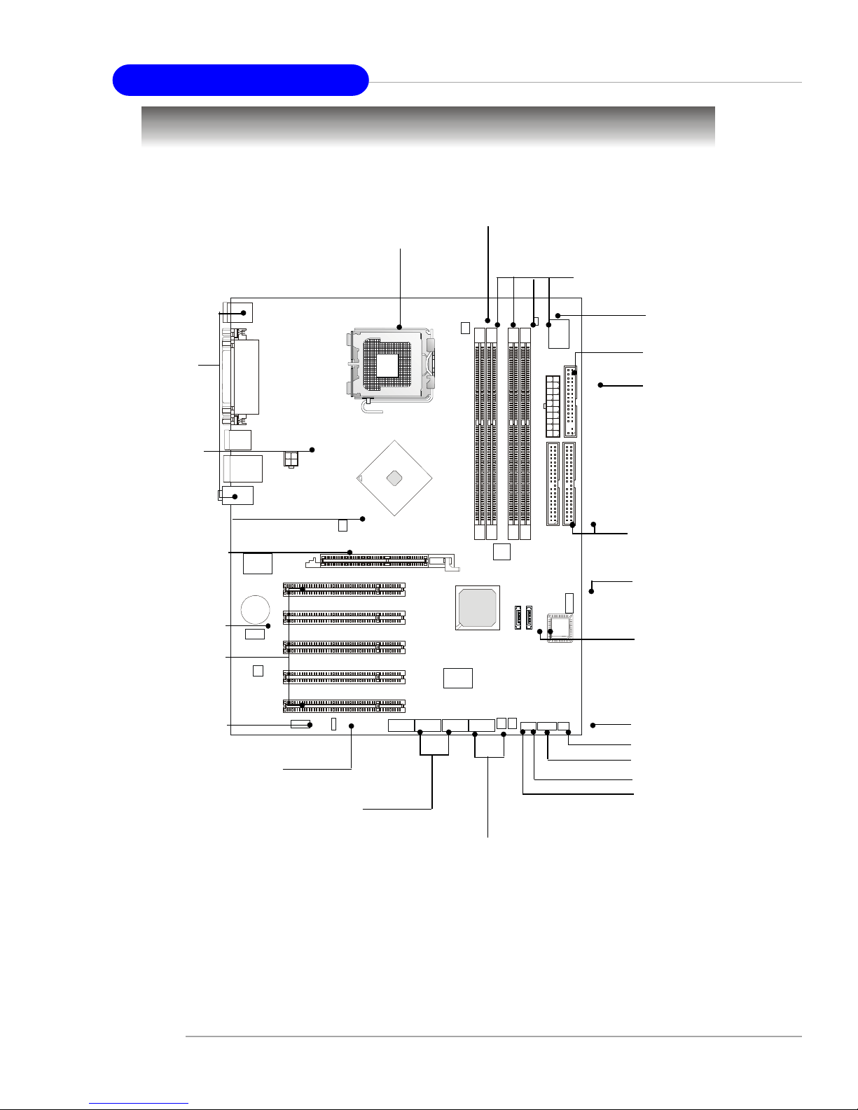
Quick Components Guide
DDR DIMMs, p.2-7
CPU, p.2-3
Back Panel
I/O, p.2-10
FDD1, p.2-14
NBFAN1,p.2-15
JUSB1, JUSB2,
p.2-24
JAUD1, p.2-23
JFP1, p.2-18
AGP Slot,
p.2-26
PCI Slots,
p.2-26
IDE1, IDE2,
p.2-16
JIR1, p.2-23
SATA1, SATA2,
p.2-17
ATX1, p.2-9
JBAT1, p.2-25
CPUFAN1, p.2-15
JCD1, p.2-24
JCI1, p.2-23
JDB1, p.2-19
JFP2, p.2-18
SFAN2, p.2-15
JPW1,
p.2-9
SFAN1, p.2-15
J1394_1, J1394_2,
p.2-22
E-2-3
Hardware Setup
Central Processing Unit: CPU
The mainboard supports Intel® Pentium 4 Prescott processor. The mainboard
uses a CPU socket called LGA775. When you are installing the CPU, make sure to
install the cooler to prevent overheating. If you do not have the CPU cooler,
contact your dealer to purchase and install them before turning on the computer.
For the latest information about CPU, please visit http://www.msi.com.tw/
program/products/mainboard/mbd/pro_mbd_cpu_support.php.
MSI Reminds You...
Overheating
Overheating will seriously damage the CPU and system, always make
sure the cooling fan can work properly to protect the CPU from
overheating.
Replacing the CPU
While replacing the CPU, always turn off the ATX power supply or
unplug the power supply’s power cord from grounded outlet first to
ensure the safety of CPU.
Overclocking
This motherboard is designed to support overclocking. However, please
make sure your components are able to tolerate such abnormal setting,
while doing overclocking. Any attempt to operate beyond product specifications is not recommended. We do not guarantee the damages
or risks caused by inadequate operation or beyond product
specifications.
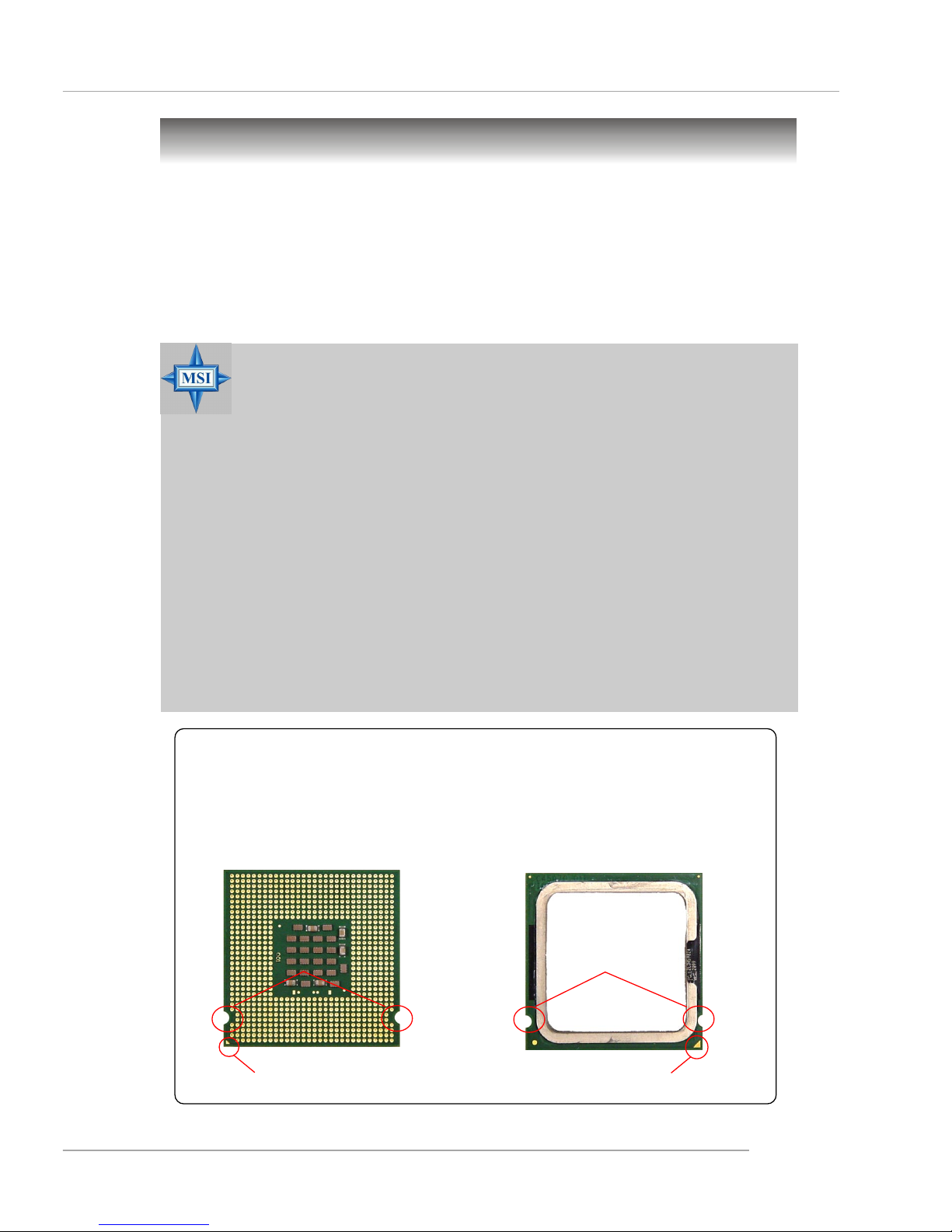
Introduction to LGA 775 CPU
The surface of LGA 775 CPU.
Remember to apply some silicone heat transfer compound on
it for better heat dispersion.
Y ellow triangle is the Pin 1 indicator
The pin-pad side of LGA 775
CPU.
Y ellow triangle is the Pin 1 indicator
Alignment Key Alignment Key
E-2-4
MS-6728 ATX Mainboard
CPU & Cooler Installation
When you are installing the CPU, make sure the CPU has a cooler at-
tached on the top to prevent overheating. If you do not have the cooler, contact
your dealer to purchase and install them before turning on the computer. Meanwhile,
do not forget to apply some silicon heat transfer compound on CPU before installing
the heat sink/cooler fan for better heat dispersion.
Follow the steps below to install the CPU & cooler correctly. Wrong installation
will cause the damage of your CPU & mainboard.
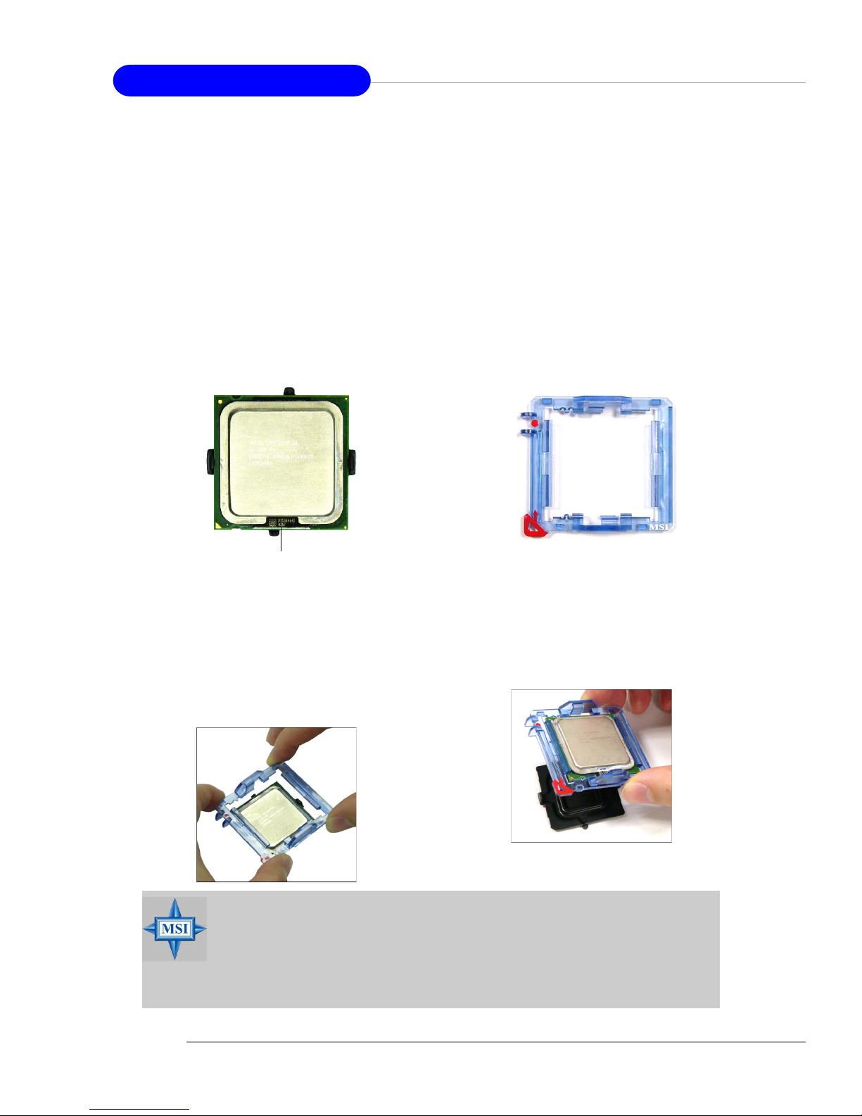
1. The CPU has a land side cover on the
bottom to protect the CPU contact from
damage. Rotate it to make the pin 1
indicator (yellow triangle) in the rightbottom corner.
2. T ake out the accompanying CPU Clip
and rotate it for the same direction
as the CPU (Pin 1 indicator, the red
triangle is in the left-bottom corner).
3. Align the 3 points (the Pin 1 indicator
and the two alignment keys) of both
the CPU and the CPU Clip, and use your
4 fingers to push the CPU Clip down to
clip them (the CPU clip is up and the
CPU is down) together.
4. The land side cover now is
removed.
land side cover
MSI Reminds You...
1. Confirm if your CPU cooler is firmly installed before turning on your
system.
2. Do not touch the CPU socket pins to avoid damaging.
3. The availability of the CPU land side cover depends on your CPU
packing.
E-2-5
Hardware Setup
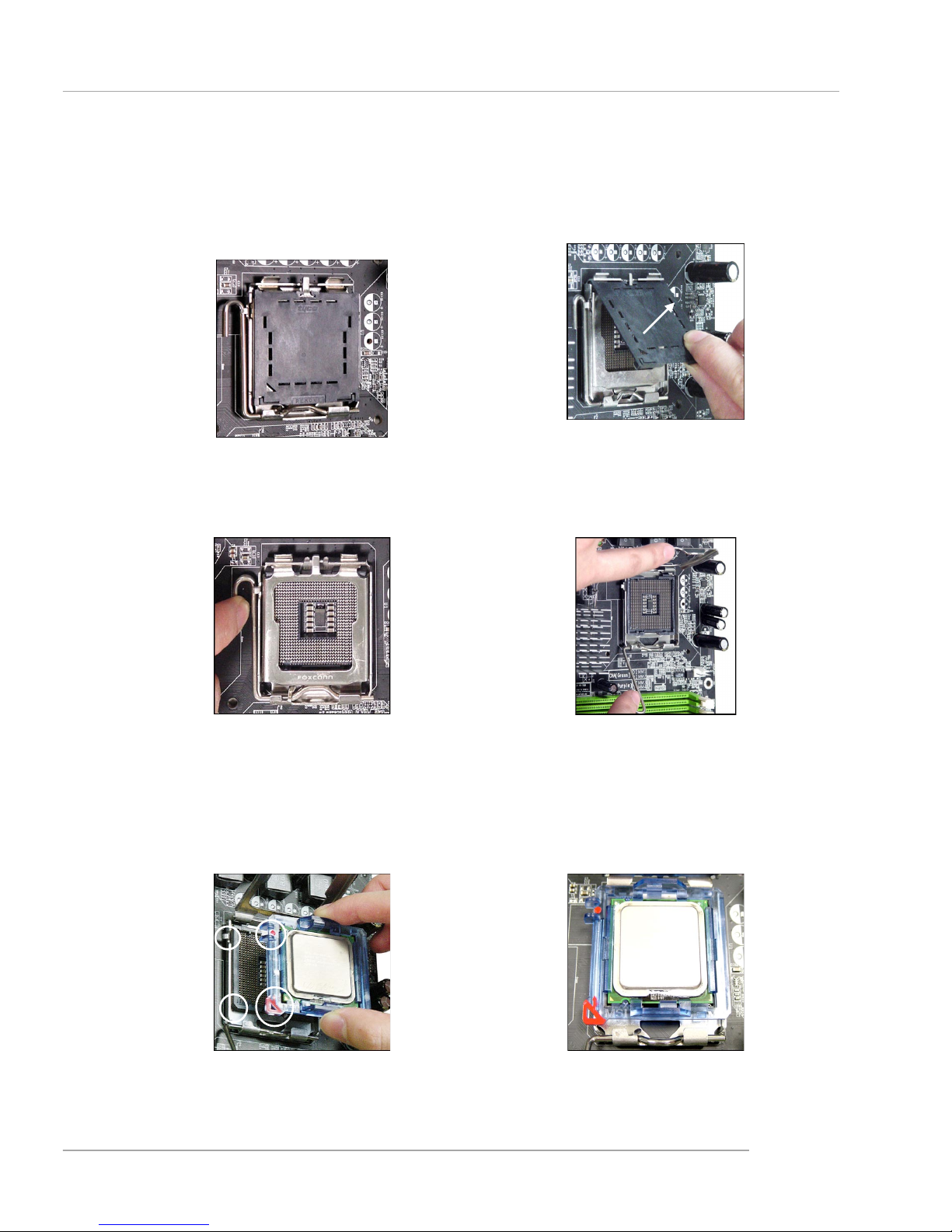
5. The CPU has a plastic cap on it to
protect the contact from damage.
Before you have installed the CPU,
always cover it to protect the socket
pin.
6. Remove the cap from lever hinge side
(as the arrow shows).
7. The pins of socket reveal. Then lift
up the load lever.
8. Lift the load lever up and open the
load plate.
9. Correctly align the red triangle of
CPU clip with the CPU chamfer, the
red arrow with the left-side socket
edge, and the red spot to the hook
of the socket.
10.Put the whole module onto the CPU
socket.
E-2-6
MS-6728 ATX Mainboard
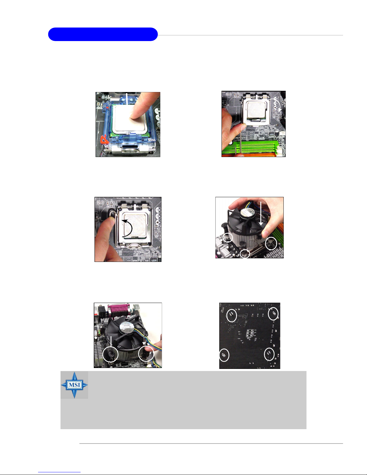
11.Push down the CPU hard to install
the CPU into the socket housing
frame.
12.Visually inspect if the CPU is seated
well into the socket, then remove the
CPU Clip with 2 fingers. Then cover
the load plate onto the package.
13. Press down the load lever lightly
onto the load plate, and then secure the lever with the hook under
retention tab.
14. Align the holes on the mainboard with
the cooler. Push down the cooler until
its four clips get wedged into the holes
of the mainboard.
16. Turn over the mainboard to confirm
that the clip-ends are correctly
inserted.
15. Press the four hooks down to fasten the cooler. Then rotate the locking switch (refer to the correct direction marked on it) to lock the
hooks.
locking
switch
MSI Reminds You...
1.Check the information in PC Health Status in BIOS (refer to p.3-25 for
details) for the CPU temperature.
2. Whenever CPU is not installed, always protect your CPU socket pin
with the plastic cap covered (shown in Figure 1) to avoid damaging.
3. Please note that the mating/unmating durability of the CPU is 20 cycles.
Therefore we suggest you do not plug/unplug the CPU too often.
E-2-7
Hardware Setup
Memory
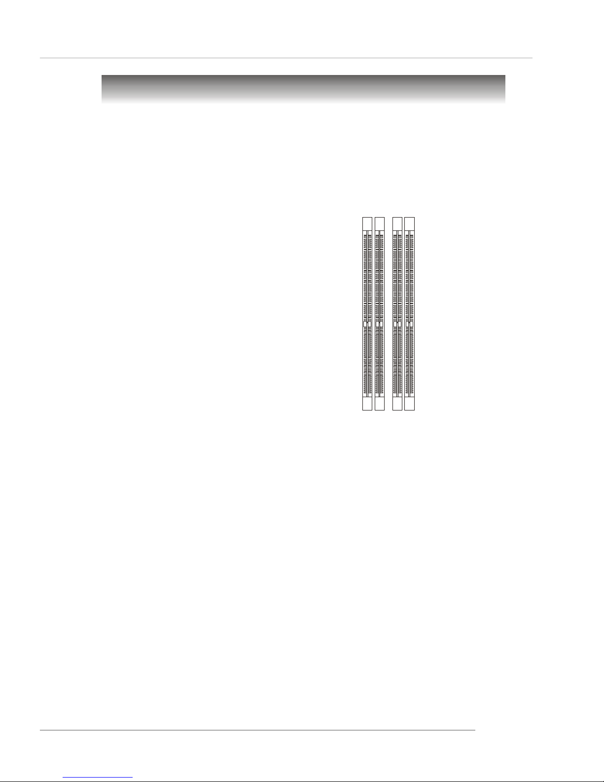
DDR DIMM Slots
(DIMM 1~4, from left to right)
Channel A: DIMM1 & DIMM2 (green)
Channel B: DIMM3 & DIMM4 (purple)
The mainboard provides 4 slots for 184-pin, 2.5V DDR DIMM with 8 memory
banks. You can install DDR266 / DDR333 / DDR400 / DDR433 / DDR466 / DDR500 /
DDR533 SDRAM modules on the DDR DIMM slots (DIMM 1~4). To operate properly, at
least one DIMM module must be installed. Please note that DDR433 / DDR466 /
DDR500 / DDR533 are for overclocking spec.
Introduction to DDR SDRAM
DDR (Double Data Rate) SDRAM is similar to conventional SDRAM, but doubles the rate by transferring data twice per cycle. It uses 2.5 volts as opposed to 3.
3 volts used in SDR SDRAM, and requires 184-pin DIMM modules rather than 168-pin
DIMM modules used by SDR SDRAM. Please note that the DDR SDRAM does not
support ECC (error correcting code) and registered DIMM.
DDR Population Rules
Install at least one DIMM module on the slots. Each DIMM slot supports up to a
maximum size of 1GB. Users can install either single- or double-sided modules to
meet their own needs. Please note that each DIMM can work respectively for
single-channel DDR, but there are some rules while using dual-channel
DDR (Please refer to the suggested DDR population table on p.2-8). Users may install
memory modules of different type and density on different-channel DDR DIMMs.
However, the same type and density memory modules are necessary while
using dual-channel DDR, or instability may happen.
E-2-8
MS-6728 ATX Mainboard
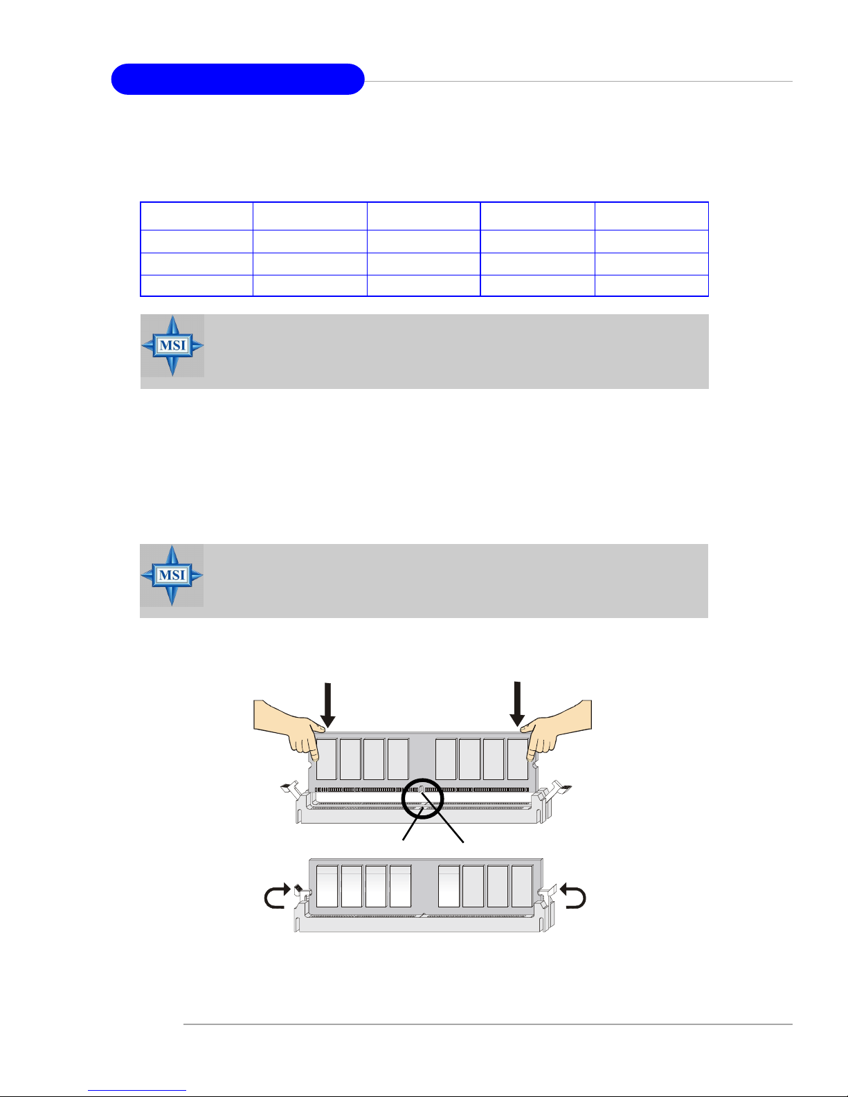
Installing DDR Modules
1. The DDR DIMM has only one notch on the center of module. The module will only
fit in the right orientation.
2. Insert the DIMM memory module vertically into the DIMM slot. Then push it in until the
golden finger on the memory module is deeply inserted in the socket.
3. The plastic clip at each side of the DIMM slot will automatically close.
Volt
Notch
MSI Reminds You...
Dual-channel DDR works ONLY in the 3 combinations listed in the
table above.
DIMM1 (Ch A) DIMM2 (Ch A) DIMM3 (Ch B) DIMM4 (Ch B) System Density
128MB~1GB 128MB~1GB 256MB~2GB
128MB~1GB 128MB~1GB 256MB~2GB
128MB~1GB 128MB~1GB 128MB~1GB 128MB~1GB 512MB~4GB
Please refer to the following table for detailed dual-channel DDR. Other combination not listed below will function as single-channel DDR.
MSI Reminds You...
You can barely see the golden finger if the module is properly inserted
in the socket.
E-2-9
Hardware Setup
Power Supply
The mainboard supports ATX power supply for the power system. Before
inserting the power supply connector, always make sure that all components are
installed properly to ensure that no damage will be caused.
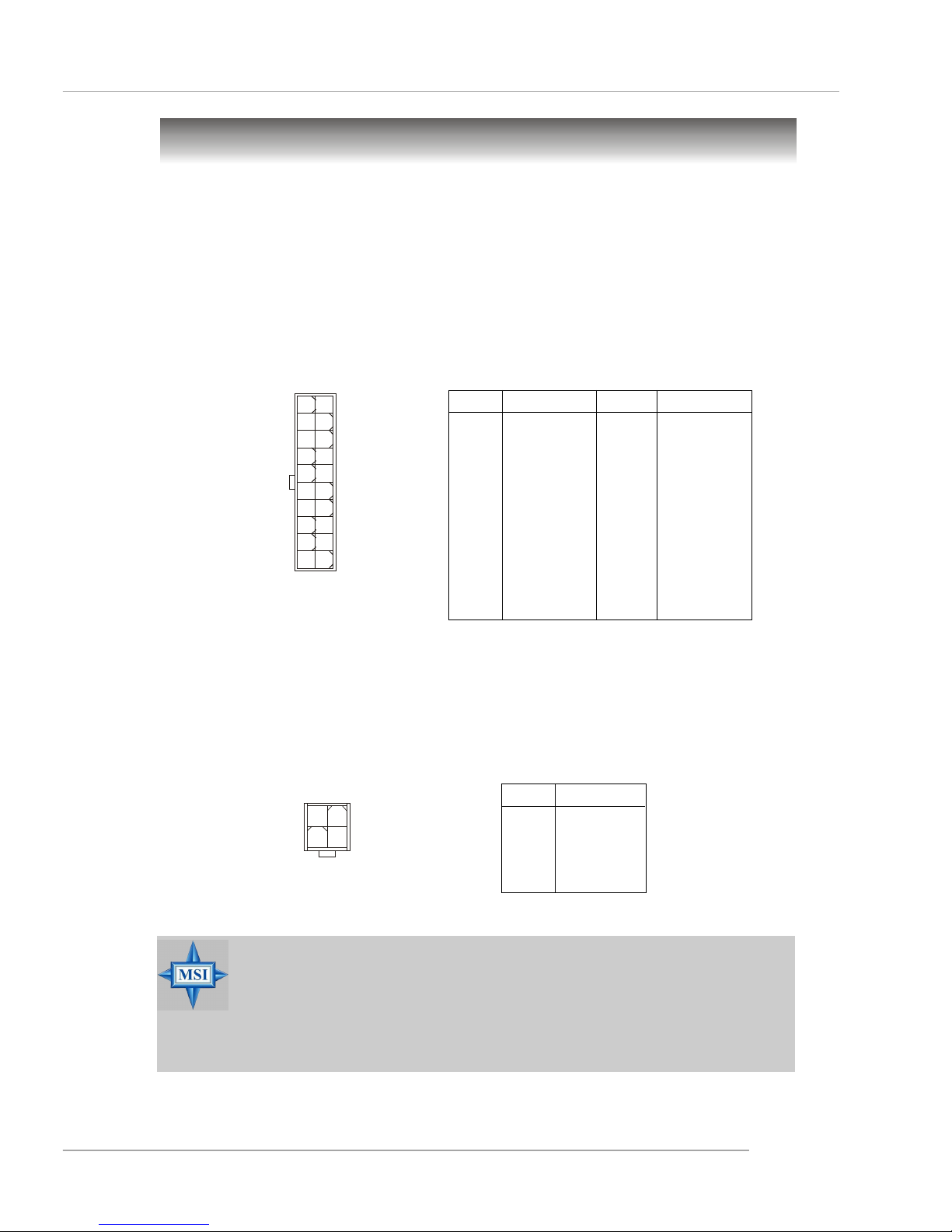
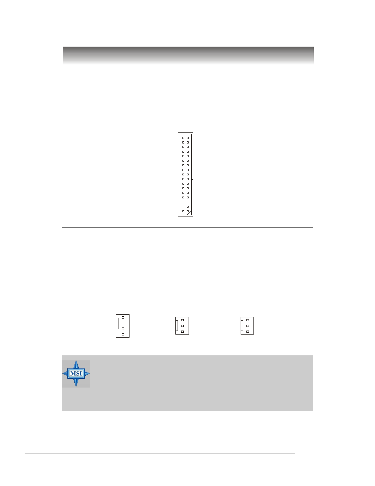
ATX 20-Pin Power Connector: ATX1
This connector allows you to connect to an ATX power supply. To connect to
the ATX power supply, make sure the plug of the power supply is inserted in the
proper orientation and the pins are aligned. Then push down the power supply firmly
into the connector.
ATX 12V Power Connector: JPW1
This 12V power connector is used to provide power to the CPU.
PIN SIGNAL
1 GND
2 GND
3 12V
4 12V
JPW1 Pin Definition
PIN SIGNAL
11 3.3V
12 -12V
13 GND
14 PS_ON
15 GND
16 GND
17 GND
1 8 -5V
19 5V
20 5V
PIN SIGNAL
1 3.3V
2 3.3V
3 GND
45V
5 GND
65V
7 GND
8 PW_OK
9 5V_SB
10 12V
ATX1 Pin Definition
ATX1
10
1
20
11
JPW1
1
34
2
MSI Reminds You...
1. These two connectors connect to the ATX power supply and have to
work together to ensure stable operation of the mainboard.
2. Power supply of 350 watts (and above) is highly recommended for
system stability.
3. ATX 12V power connection should be greater than 18A.
E-2-10
MS-6728 ATX Mainboard
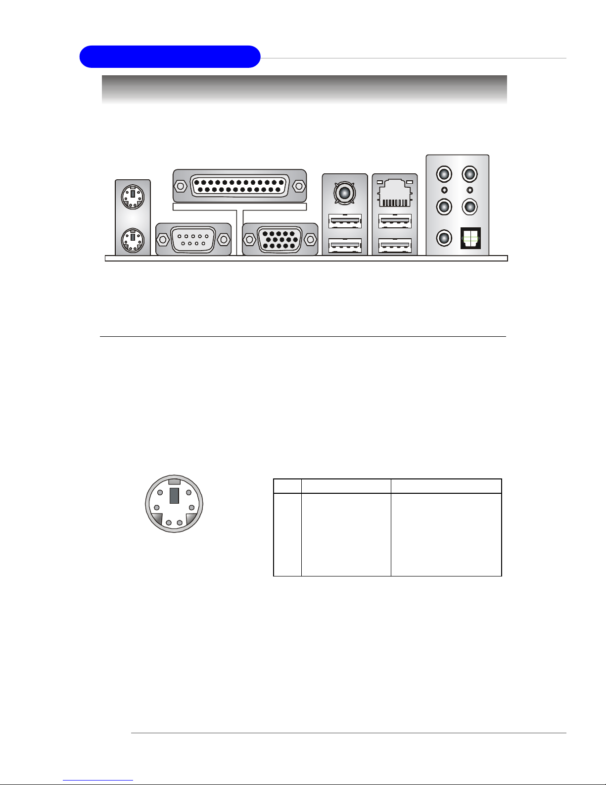
The back panel provides the following connectors:
Back Panel
Mouse/Keyboard Connector
The mainboard provides a standard PS/2® mouse/keyboard mini DIN connector for attaching a PS/2® mouse/keyboard. You can plug a PS/2® mouse/keyboard
directly into this connector. The connector location and pin assignments are as
follows:
PS/2 Mouse / Keyboard
(6-pin Female)
2
1
3
4
5
6
PIN SIGNAL DESCRIPTION
1 Mouse/Keyboard Data Mouse/Keyboard data
2 NC No connection
3 GND Ground
4 VCC +5V
5 Mouse/Keyboard Clock Mouse/Keyboard clock
6 NC No connection
Pin Definition
Keyboard
COM A
USB Ports
Mic
L-Out
L-In
Mouse
Parallel
LAN
VGA port
(Optional)
S/PDIF
RS-Out
SPDIF Out
CS-Out
E-2-11
Hardware Setup
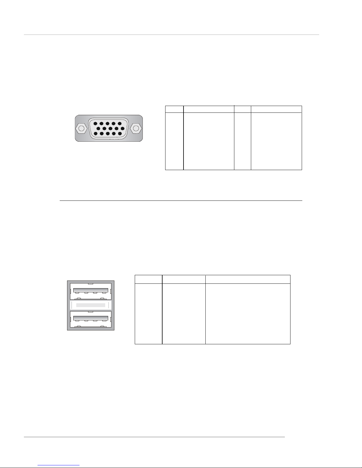
VGA Connector (Optional, for 865G only)
The mainboard provides a DB 15-pin female connector to connect a VGA
monitor.
VGA Connector
(DB 15-pin)
1
5
11
15
Pin Signal Description Pin Signal Description
1 RED 2 GREEN
3 BLUE 4 N/C
5 GND 6 GND
7 GND 8 GND
9 +5V 10 GND
1 1 N/C 12 SDA
13 Horizontal Sync 14 Vertical Sync
15 SCL
PIN SIGNAL DESCRIPTION
1 VCC +5V
2 -Data 0 Negative Data Channel 0
3 +Data0 Positive Data Channel 0
4 GND Ground
5 VCC +5V
6 -Data 1 Negative Data Channel 1
7 +Data 1 Positive Data Channel 1
8 GND Ground
USB Port Description
USB Connectors
The mainboard provides an OHCI (Open Host Controller Interface) Universal
Serial Bus root for attaching USB devices such as keyboard, mouse or other USBcompatible devices. You can plug the USB device directly into the connector.
USB Ports
1 2 3 4
5 6 7 8
E-2-12
MS-6728 ATX Mainboard
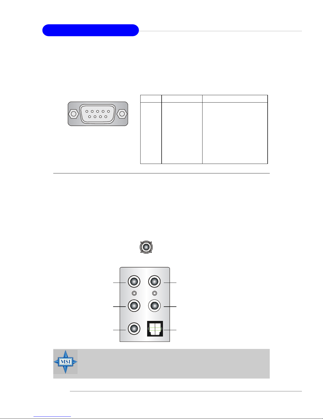
Serial Port Connector
The mainboard offers one 9-pin male DIN connector as the serial port. The port
is a 16550A high speed communication port that sends/receives 16 bytes FIFOs. You
can attach a serial mouse or other serial devices directly to the connector.
PIN SIGNAL DESCRIPTION
1 DCD Data Carry Detect
2 SIN Serial In or Receive Data
3 SOUT Serial Out or Transmit Data
4 DTR Data T erminal Ready)
5 GND Ground
6 DSR Data Set Ready
7 RTS Request T o Send
8 CTS Clear T o Send
9 RI Ring Indicate
Pin Definition
9-Pin Male DIN Connector
1 2 3 4 5
6 7 8 9
Audio Port Connectors
The left 3 audio jacks are for 2-channel mode for stereo speaker output: Line
Out is a connector for Speakers or Headphones. Line In is used for external CD
player, Tape player, or other audio devices. Mic is a connector for microphones.
However , there is an advanced audio application provided by Realtek ALC850
to offer support for 7.1-channel audio operation and can turn rear audio connectors from 2-channel to 4-/5.1-/7.1- channel audio.
S/PDIF Out-Coaxial
Rear Speaker Out
(in 7.1CH / 5.1CH)
Line Out
Line In
MIC
Center/Subwoofer
Speaker Out
( in 7.1CH / 5.1CH)
S/PDIF Out-Optical
MSI Reminds You...
For the advanced functions of the audio codec, please refer to Chapter
6: Introduction to RealTek ALC850 Audio Codec for details.
E-2-13
Hardware Setup
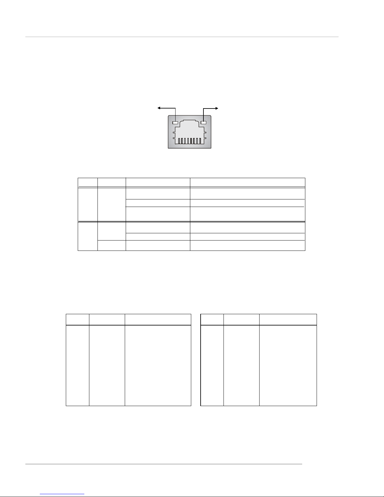
RJ-45 LAN Jack: 10/100 LAN (8100C) /Giga-bit LAN (8110S) (Optional)
The mainboard provides two standard RJ-45 jacks for connection to Local
Area Network (LAN). Giga-bit LAN enables data to be transferred at 1000, 100 or
10Mbps. You can connect a network cable to either LAN jack.
The pin assignments vary depending on the transfer rates: 10/100Mbps or
1000Mbps. Note that Pin 1/2, 3/6, 4/5, 7/8 must work in pairs. Please refer
to the following for details:
10/100 LAN Pin Definition Giga-bit LAN Pin Definition
PIN SIGNAL DESCRIPTION
1 D0P Differential Pair 0+
2 D0N Differential Pair 0 3 D1P Differential Pair 1+
4 D2P Differential Pair 2+
5 D2N Differential Pair 2 6 D1N Differential Pair 1 7 D3P Differential Pair 3+
8 D3N Differential Pair 3-
PIN SIGNAL DESCRIPTION
1 TD P Transmit Differential Pair
2 TDN Transmit Differential Pair
3 RDP Receive Differential Pair
4 NC Not Used
5 NC Not Used
6 RDN Receive Differential Pair
7 NC Not Used
8 NC Not Used
LED Color LED State Condition
Off LAN link is not established.
Left Orange On (steady state) LAN link is established.
On (brighter & pulsing) The computer is communicating with another
computer on the LAN.
Green Off 10 Mbit/sec data rate is selected.
Right On 100 Mbit/sec data rate is selected.
Orange On 1000 Mbit/sec data rate is selected.
Link Indicator
8 1
Activity Indicator
RJ-45 LAN Jack
E-2-14
MS-6728 ATX Mainboard
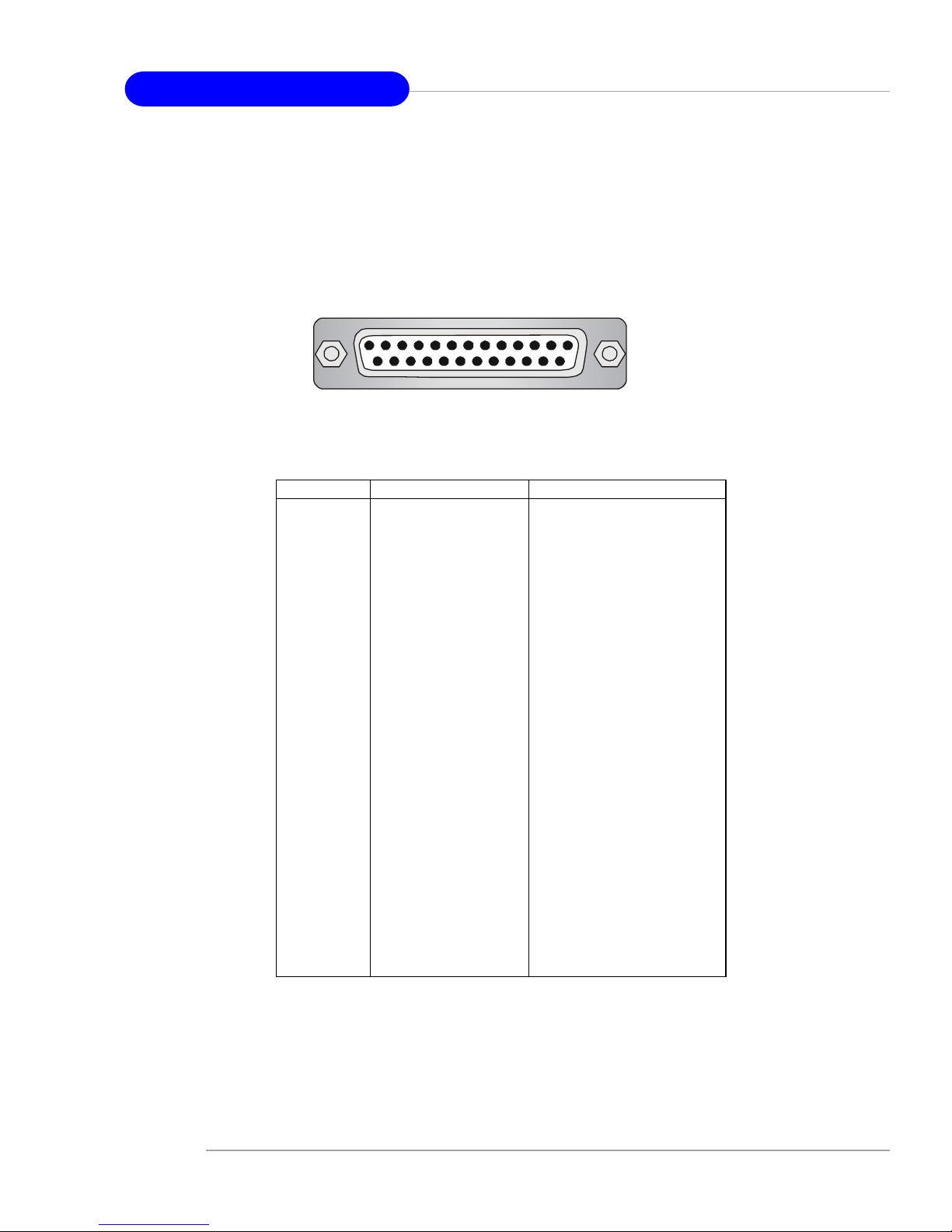
Parallel Port Connector: LPT1
The mainboard provides a 25-pin female centronic connector as LPT. A
parallel port is a standard printer port that supports Enhanced Parallel Port (EPP) and
Extended Capabilities Parallel Port (ECP) mode.
PIN SIGNAL DESCRIPTION
1 STROBE Strobe
2 DATA0 Data0
3 DATA1 Data1
4 DATA2 Data2
5 DATA3 Data3
6 DATA4 Data4
7 DATA5 Data5
8 DATA6 Data6
9 DATA7 Data7
10 ACK# Acknowledge
11 BUSY Busy
12 PE Paper End
1 3 SELECT Select
1 4 AUTO FEED# Automatic Feed
15 ERR# Error
1 6 INIT# Initialize Printer
17 SLIN# Select In
18 GND Ground
19 GND Ground
20 GND Ground
21 GND Ground
22 GND Ground
23 GND Ground
24 GND Ground
25 GND Ground
Pin Definition
13 1
14
25
E-2-15
Hardware Setup
The mainboard provides connectors to connect to FDD, IDE HDD, LAN, USB
Ports, IR module and CPU/System/NB FAN.
Floppy Disk Drive Connector: FDD1
The mainboard provides a standard floppy disk drive connector that supports
360K, 720K, 1.2M, 1.44M and 2.88M floppy disk types.
Connectors
FDD1
Fan Power Connectors: CPUFAN1/SF AN1/SF AN2/NBF AN1
The CPUFAN1 (processor fan), SFAN1/SFAN2 (system fans) and NBFAN1
(NorthBridge Chipset fan) support system cooling fan with +12V. It supports four/
three-pin head connector. When connecting the wire to the connectors, always take
note that the red wire is the positive and should be connected to the +12V, the black
wire is Ground and should be connected to GND. If the mainboard has a System
Hardware Monitor chipset on-board, you must use a specially designed fan with
speed sensor to take advantage of the CPU fan control.
NBFAN1SFAN1, SFAN2
NC
+12V
GND
+12V
GND
Sensor
CPUFAN1
SENSOR
+12V
GND
Control
MSI Reminds You...
1. Always consult the vendors for proper CPU cooling fan.
2. CPUFAN1 supports the fan control. Fan/heatsink with 3 or 4 pins
are both available.
3. Please refer to the recommended CPU fans at Intel® official
website.
E-2-16
MS-6728 ATX Mainboard
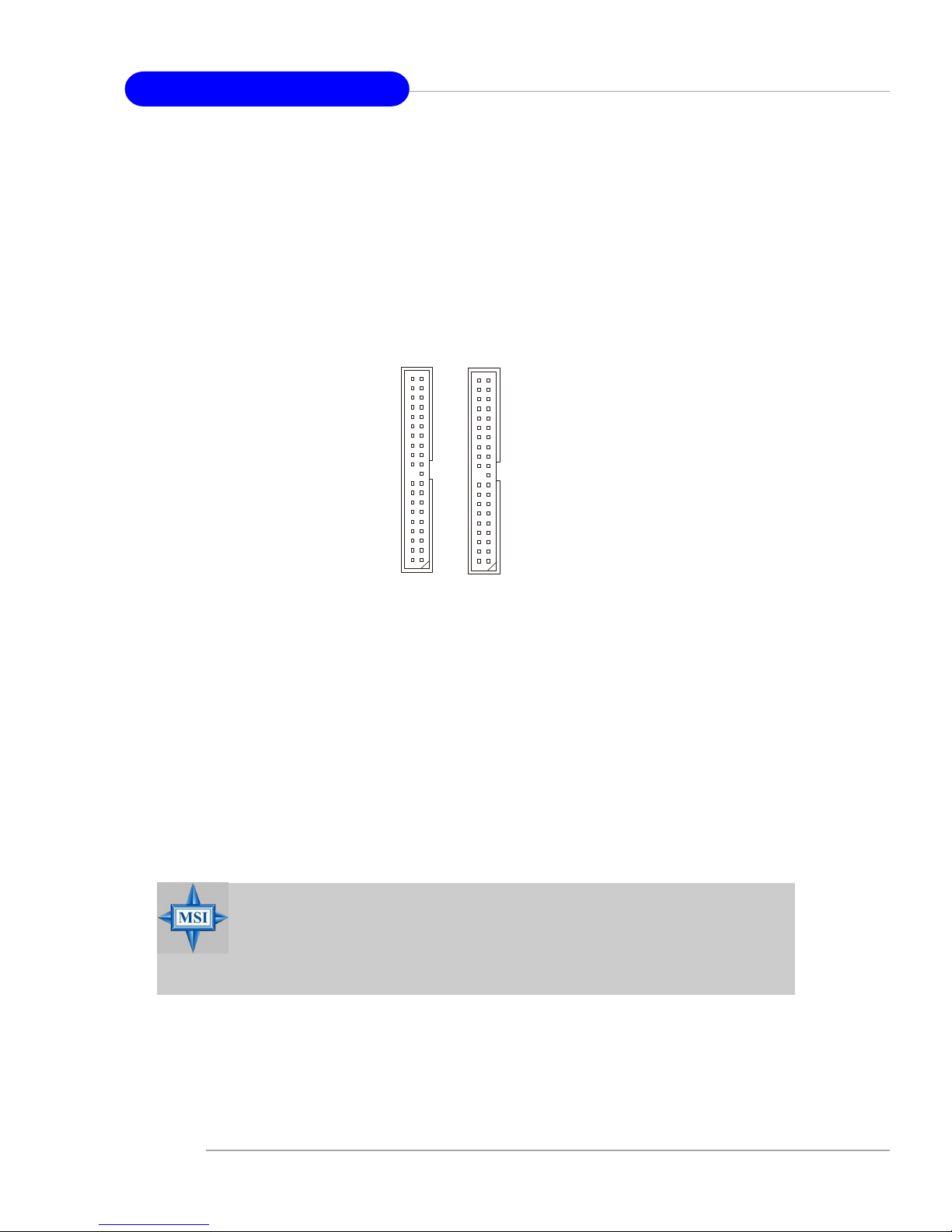
A T A100 Hard Disk Connectors: IDE1 & IDE2
The mainboard has a 32-bit Enhanced PCI IDE and Ultra DMA 66/100 controller
that provides PIO mode 0~4, Bus Master, and Ultra DMA 66/100 function. You can
connect up to four hard disk drives, CD-ROM and other IDE devices.
The Ultra ATA100 interface boosts data transfer rates between the computer
and the hard drive up to 100 megabytes (MB) per second. The new interface is onethird faster than earlier record-breaking Ultra ATA/100 technology and is backward
compatible with the existing Ultra ATA interface.
IDE1 (Primary IDE Connector)
The first hard drive should always be connected to IDE1. IDE1 can connect a Master
and a Slave drive. You must configure second hard drive to Slave mode by setting the
jumper accordingly.
IDE2 (Secondary IDE Connector)
IDE2 can also connect a Master and a Slave drive.
IDE1IDE2
MSI Reminds You...
If you install two hard disks on cable, you must configure the second
drive to Slave mode by setting its jumper. Refer to the hard disk documentation supplied by hard disk vendors for jumper setting instructions.
E-2-17
Hardware Setup
MSI Reminds You...
Please do not fold the serial ATA cable in a 90-degree angle, for this
might cause the loss of data during the transmission.
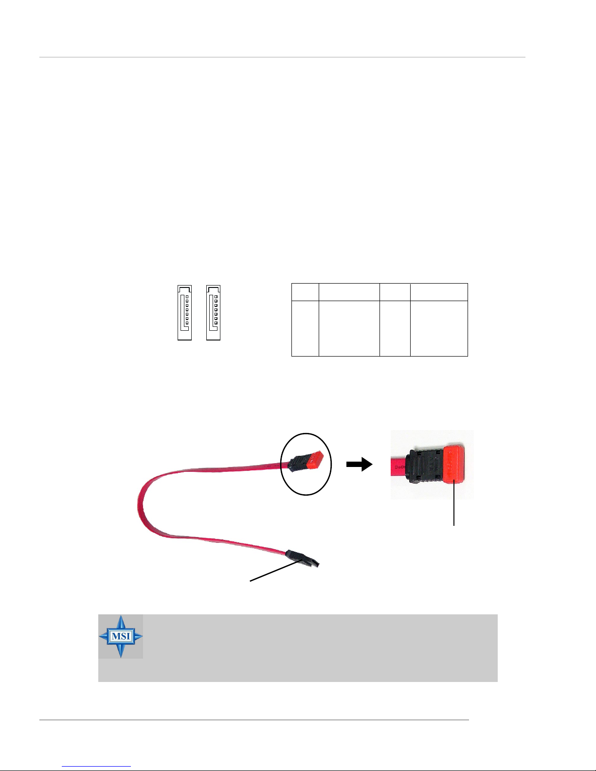
PIN SIGNAL PIN SIGNAL
1 GND 2 TXP
3 TXN 4 GND
5 RXN 6 RXP
7 GND
SA TA1~ SA T A2 Pin Definition
Serial A T A / Serial A TA RAID Connectors controlled by ICH5 / ICH5R:
SA T A1, SA T A2
The Southbridge of this mainboard is ICH5/ICH5R which supports two serial
connectors SATA1 & SATA2.
SATA1 & SATA2 are dual high-speed Serial ATA interface ports. Each supports 1st generation serial ATA data rates of 150 MB/s. Both connectors are fully
compliant with Serial ATA 1.0 specifications. Each Serial ATA connector can connect
to 1 hard disk device.
For the advanced functions of the Serial ATA RAID, please refer to Chapter
5: Introduction to Intel ICH5R Serial ATA RAID for details.
7
1
SATA2 SATA1
Connect to serial ATA ports
Take out the dust cover and
connect to the hard disk
devices
Optional Serial A TA cable
E-2-18
MS-6728 ATX Mainboard
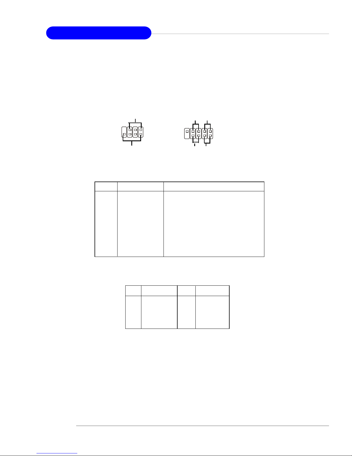
Front Panel Connectors: JFP1 & JFP2
The mainboard provides two front panel connectors for electrical connection
to the front panel switches and LEDs. JFP1 is compliant with Intel® Front Panel I/O
Connectivity Design Guide.
JFP1
1
9
10
HDD
LED
Reset
Switch
Power
LED
Power
Switch
2
JFP2
Speaker
Power
LED
7
8
2
1
PIN SIGNAL DESCRIPTION
1 HD_LED_P Hard disk LED pull-up
2 FP PWR/SLP MSG LED pull-up
3 HD_LED_N Hard disk active LED
4 FP PWR/SLP MSG LED pull-up
5 RST_SW_N Reset Switch low reference pull-down to GND
6 PWR_SW_P Power Switch high reference pull-up
7 RST_SW_P Reset Switch high reference pull-up
8 PWR_SW_N Power Switch low reference pull-down to GND
9 RSVD_DNU Reserved. Do not use.
JFP1 Pin Definition
PIN SIGNAL PIN SIGNAL
1 GND 2 SPK3 SLED 4 BUZ+
5 PLED 6 BUZ7 NC 8 SPK+
JFP2 Pin Definition
E-2-19
Hardware Setup
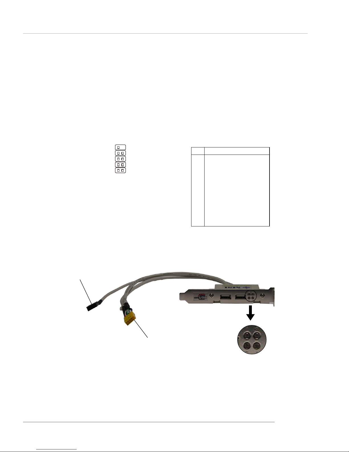
D-Bracket™ 2 Connector: JDB1
The mainboard comes with a JDB1 connector for you to connect to DBracket™ 2, which supports both USB 1.1 & 2.0 spec.
D-Bracket™ 2 is a USB bracket integrating four Diagnostic LEDs, which use
graphic signal display to help users understand their system. The LEDs provide up to
16 combinations of signals to debug the system. The 4 LEDs can detect all problems
that fail the system, such as VGA, RAM or other failures. This special feature is very
useful for overclocking users. These users can use the feature to detect if there are
any problems or failures.
Pin Signal
1 DBG1 (high for green color)
2 DBR1 (high for red color)
3 DBG2 (high for green color)
4 DBR2 (high for red color)
5 DBG3 (high for green color)
6 DBR3 (high for red color)
7 DBG4 (high for green color)
8 DBR4 (high for red color)
9 Key (no pin)
10 NC
JDB1 Pin Definition
JDB1
1
9
2
10
Connected to JUSB1
Connected to JDB1
LEDs
Optional D-Bracket™ 2
 Loading...