

MSI MS-1722 - Whitebook ID1 - 17, GX720 User Manual

GX720 (MS-1722)Disassemble SOP
■ 1、Battery Pack
■ 2、BOTTOM DOOR ASSY
■ 3、THERMAL-KIT And CPU Module
■ 4、RAM、WLAN And TUNER Module
■ 5、HDD Module ASSY
■ 6、ODD Module ASSY
■ 7、HINGE COVER ASSY
■ 8、UP CASE ASSY
■ 9、LOWER CASE ASSY
■ 10、LCD MODULE ASSY
GX720(MS-1722)Disassemble SOP
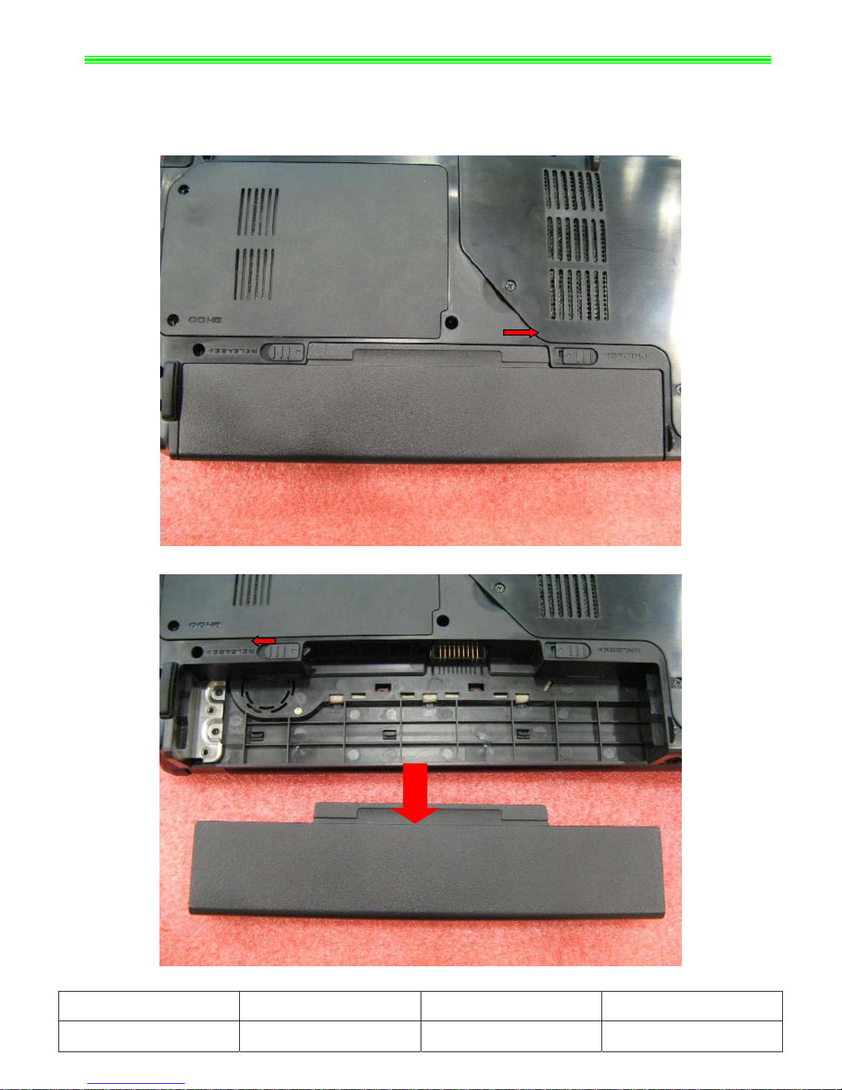
■ 1、Battery Pack
1-1:Push the battery Unlock button as below;
1-2:
Push the battery Release button as below, then slide the battery pack out of the slot;
NO. Part Name Part No. Qty
1 Battery Pack S9N-1566210-SJ3 1
GX720(MS-1722)Disassemble SOP
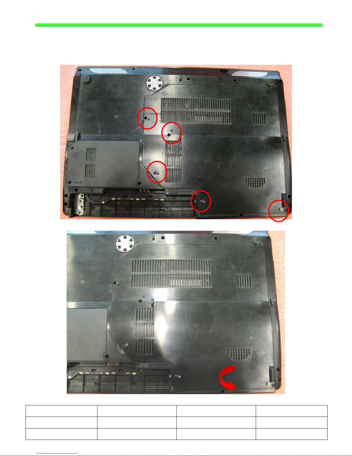
■ 2、BOTTOM DOOR ASSY
2-1:
Remove the following 5pcs M2.5*5mm screws with Screw Driver.
Note:Screw driver torque is 2.0~2.5kgf.cm
2-2:Remove Bottom Door Assy as below;
NO. Part Name Part No. Qty
1 Screw E43-I250551-H29 5
2 BOTTOM DOOR ASSY 307-721J211-Y31 1
GX720(MS-1722)Disassemble SOP
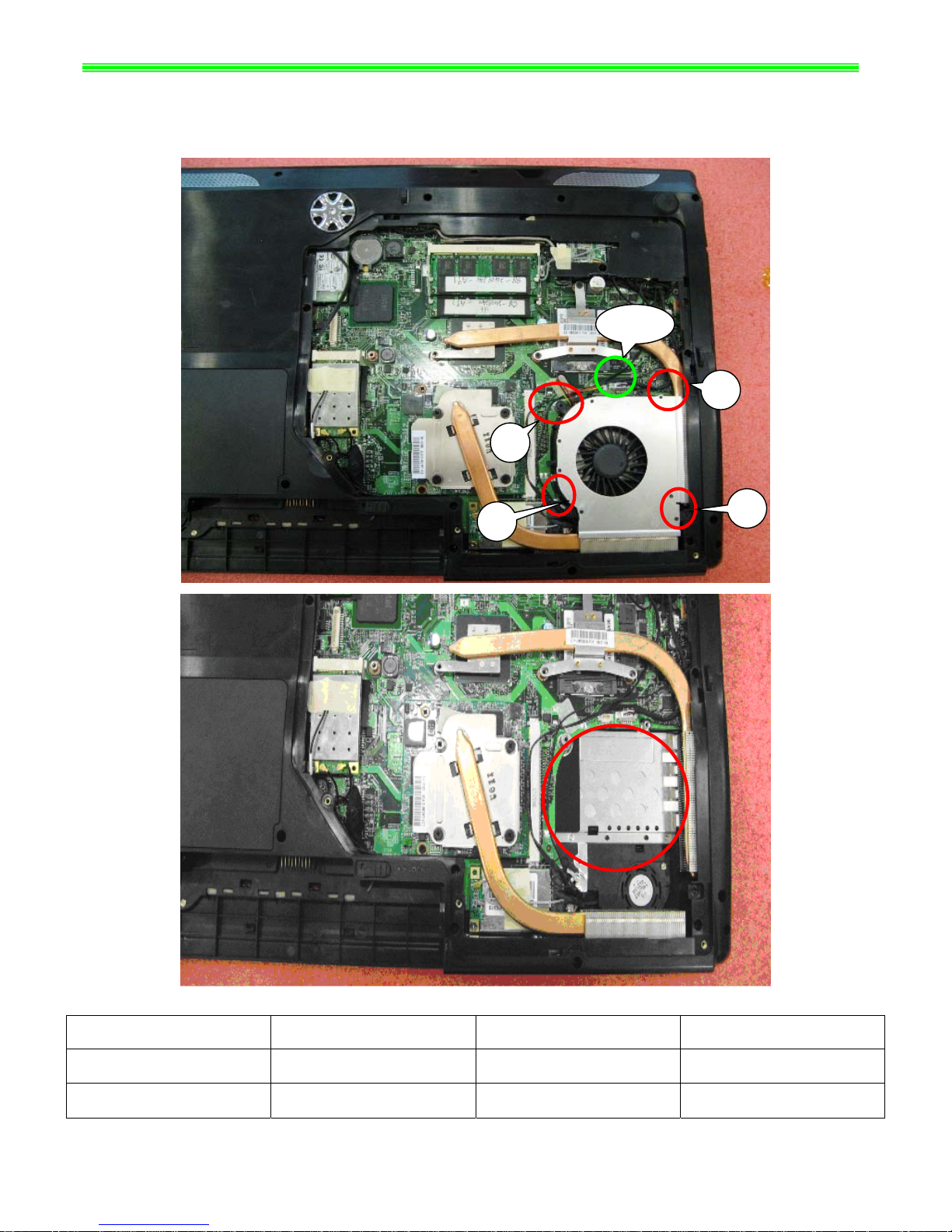
■ 3、THERMAL-KIT And CPU Module
3-1:Remove 4pcs M2.5*5mm screws, CPU Fan sink Cable and CPU Fan.
Note:Screw driver torque is 2.0~2.5kgf.cm
Cable
4
1
3
2
NO. Part Name Part No. Qty
1 Screw E43-I250551-H29 4
2 CPU FAN E33-0800050-F05 1
GX720(MS-1722)Disassemble SOP
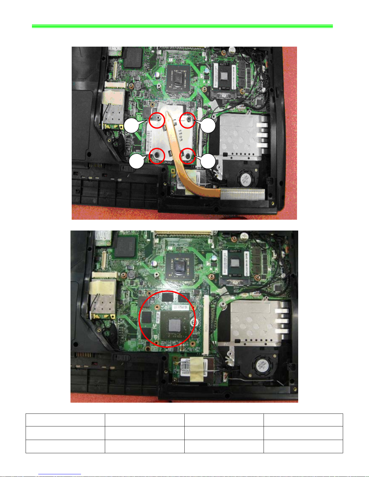
3-2:Remove the following 4pcs M2.5*5mm screws, then remove CPU Thermal Module as below;
Note:Screw driver torque is 2.0~2.5kgf.cm
3
2
4
1
NO. Part Name Part No. Qty
1 Screw E43-I250551-H29 4
2 CPU Thermal Module E31-0800610-F05 1
GX720(MS-1722)Disassemble SOP
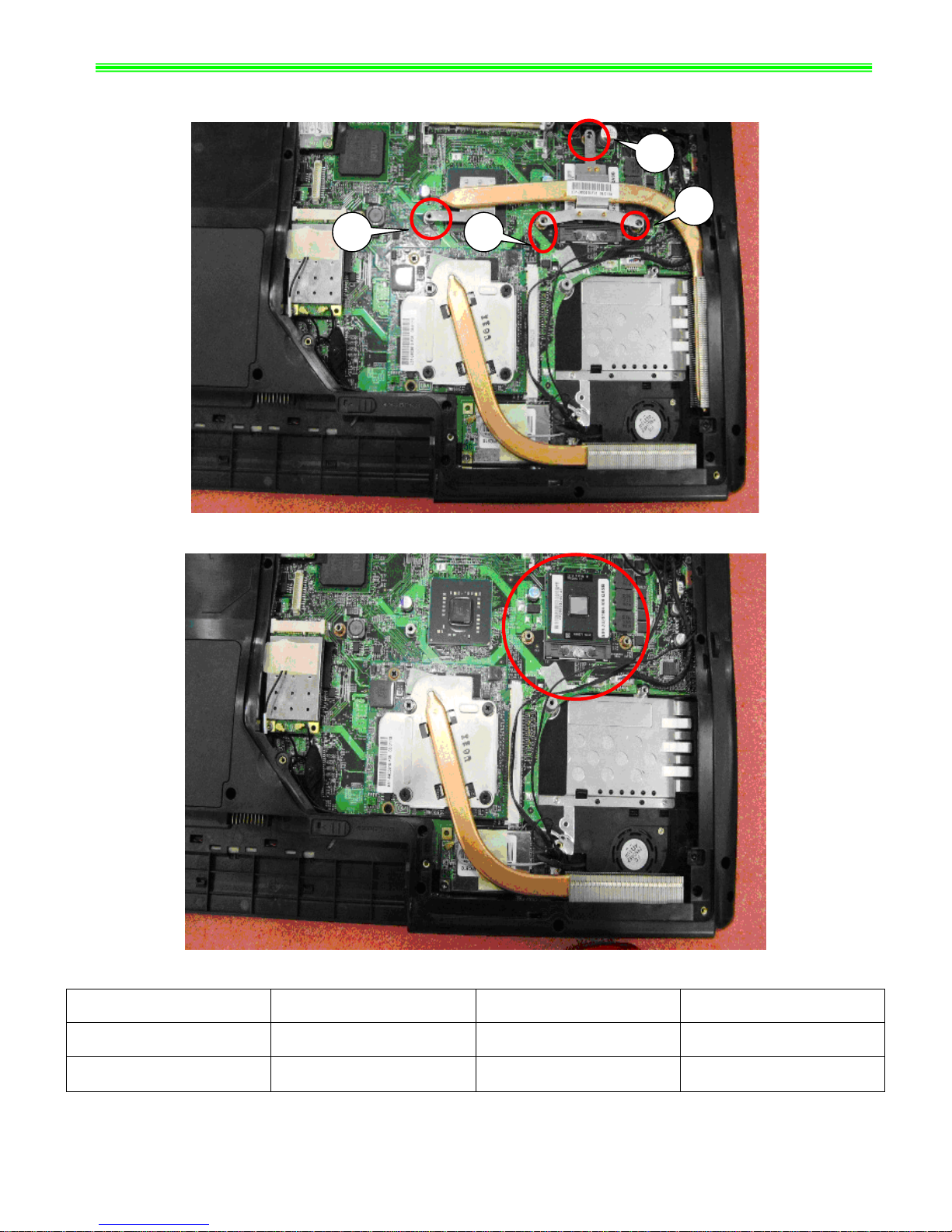
3-3:Remove 4pcs M2.5*5mm screws, Then remove MECH HEATSINK as below;
Note:Screw driver torque is 2.0~2.5kgf.cm
1
2
3
4
NO. Part Name Part No. Qty
1 Screw E43-I250551-H29 4
2 MECH HEATSINK E31-0403610-F05 1
GX720(MS-1722)Disassemble SOP
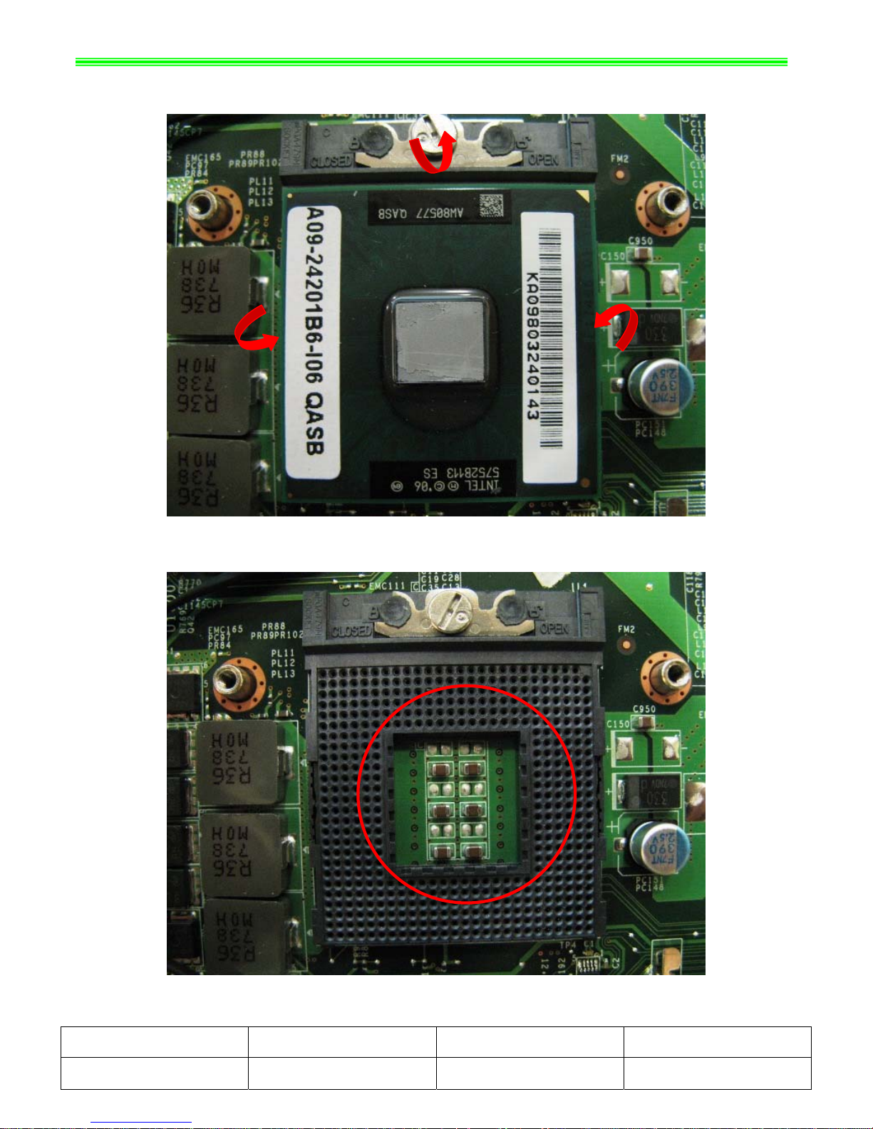
3-4: Open the CPU Slot ;
3-5:
Remove CPU Module as below;
NO. Part Name Part No. Qty
1 CPU Module A09-2420176-I06 1
GX720(MS-1722)Disassemble SOP
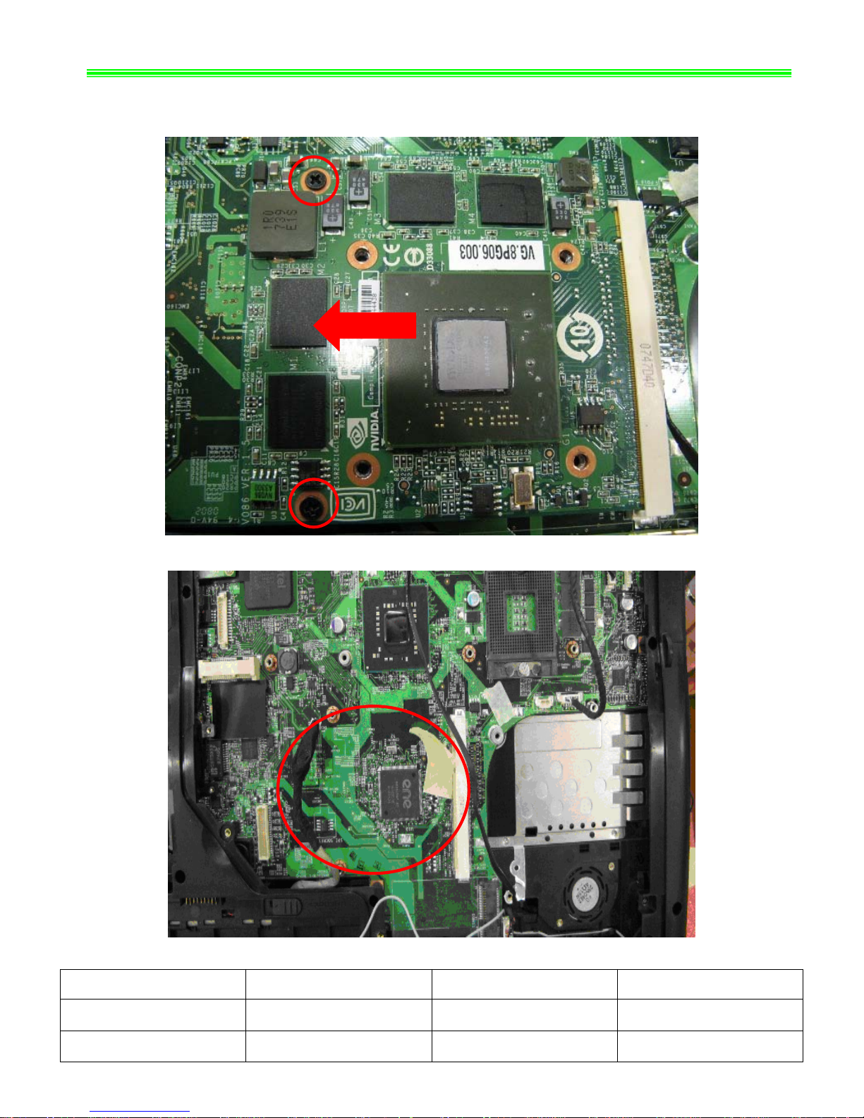
3-6:
Remove 2pcs M2.5*5mm screws, Then remove VGA Card Module as below;
Note:Screw driver torque is 2.0~2.5kgf.cm
NO. Part Name Part No. Qty
1 Screw E43-I250551-H29 2
2
VGA card 602-V114-01S 1
GX720(MS-1722)Disassemble SOP
■ 4、RAM、WLAN And TUNER Module
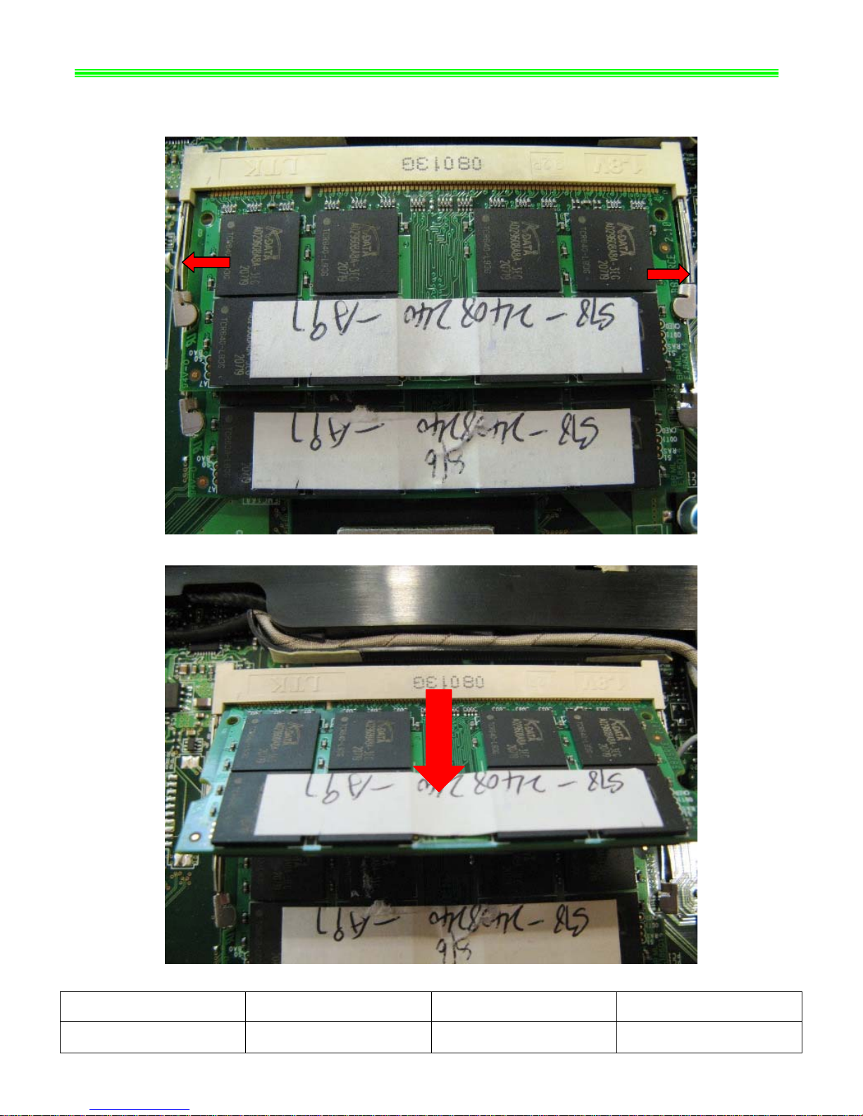
4-1:Push the RAM locks away;
4-2:
Take off the RAM Module as below:
NO. Part Name Part No. Qty
1 RAM Module S7C-S346801-T10 2
GX720(MS-1722)Disassemble SOP
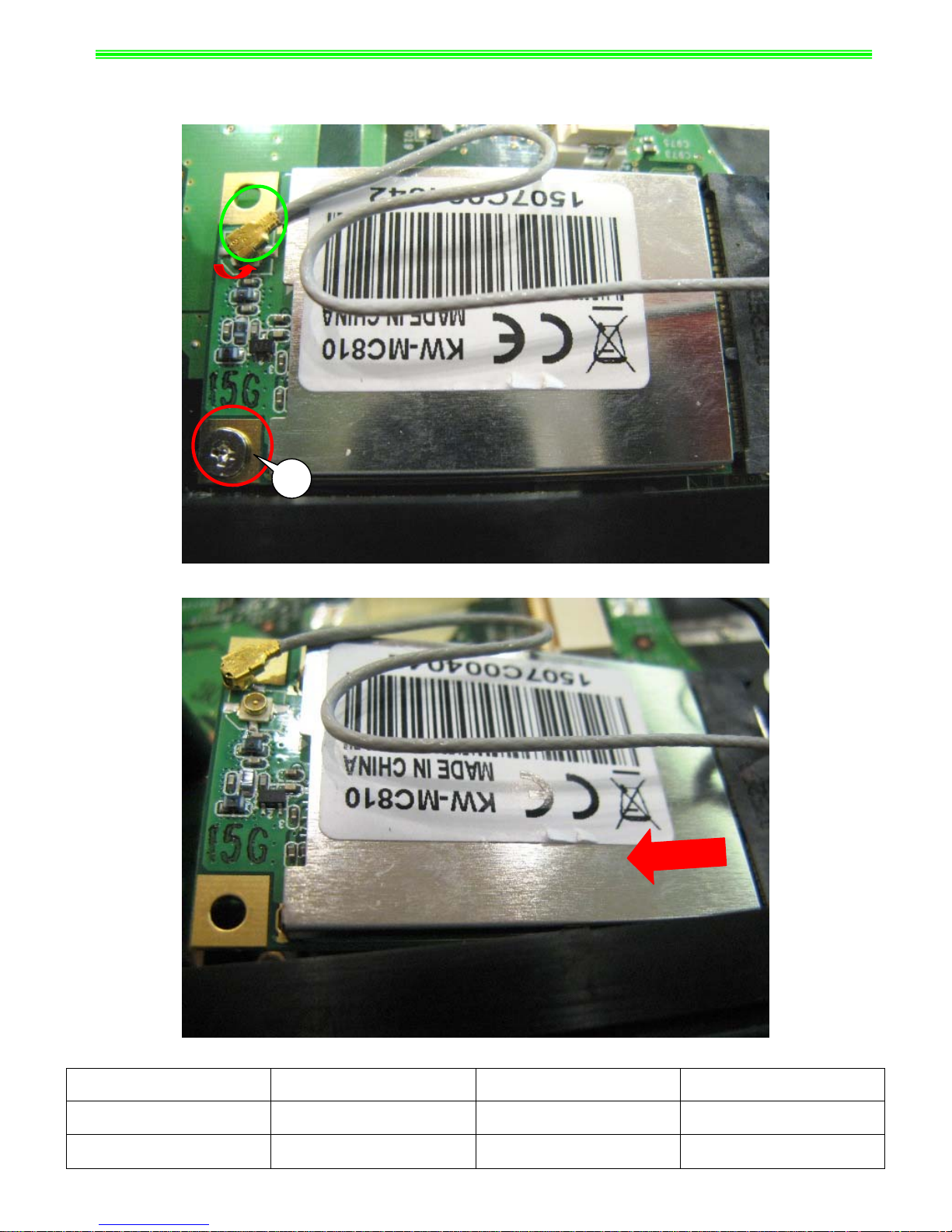
4-3
: Remove 1pcs M2*3mm screw, and then remove ANTENNA/HIGH-TEK/R-L as below;
Note:Screw driver torque is 1.0~1.5kgf.cm
1
4-4:Remove WIRELESS CARD as below;
NO. Part Name Part No. Qty
1
Screw E43-1303501-H29 1
2
WIRELESS CARD S57-0800180-I06 1
GX720(MS-1722)Disassemble SOP
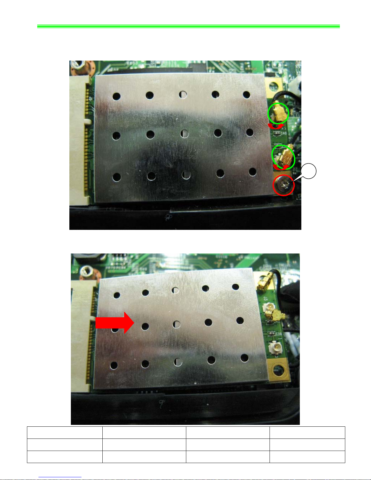
4-5:Pull out Tuner Antenna, then remove 1pcs M2*3mm Screw as below;
Note:Screw driver torque is 1.0~1.5kgf.cm
1
4-6:
Remove DVB-T MINI-PCIE CARD as below;
NO. Part Name Part No. Qty
1 Screw E43-1303501-H29 1
2 DVB-T MINI-PCIE CARD S36-0000610-K45 1
GX720(MS-1722)Disassemble SOP
■ 5、HDD Module ASSY
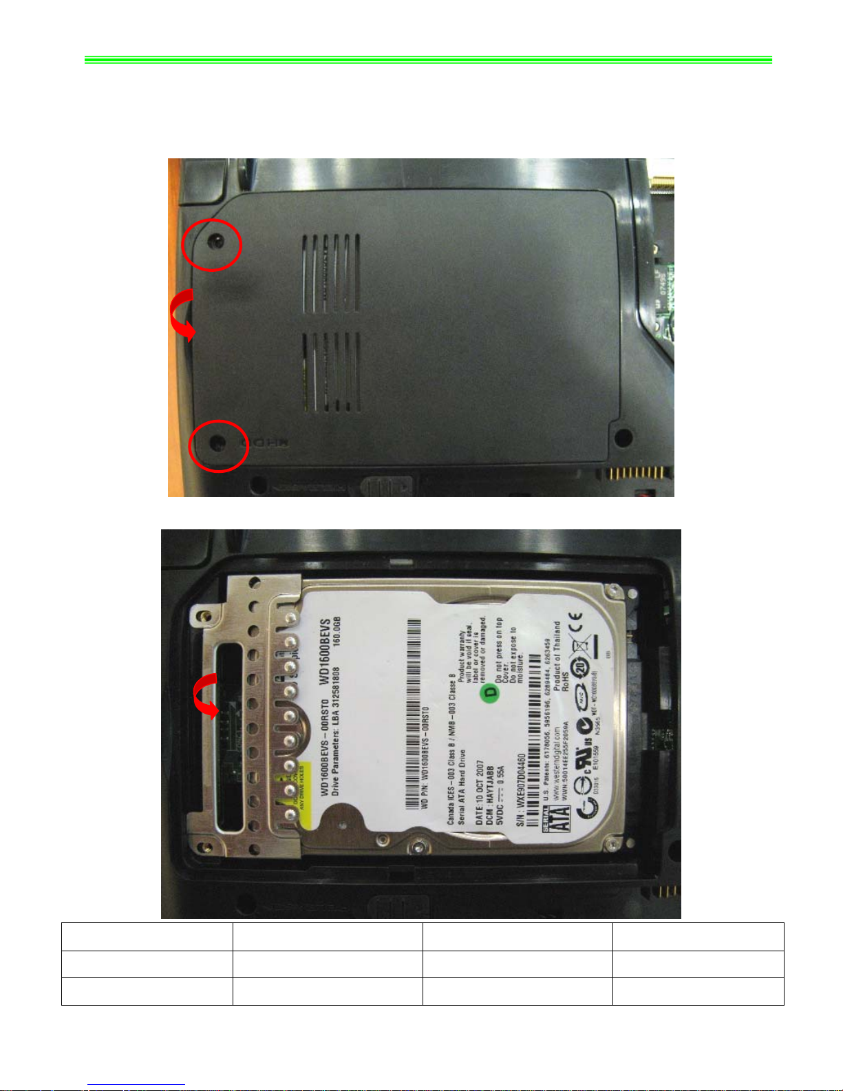
5-1:Remove 2pcs M2.5*5mm Screws , then remove HDD Door Assy as below;
Note:Screw driver torque is 2.0~2.5kgf.cm
5-2:
Remove HDD DOOR ASSY as below;
NO. Part Name Part No. Qty
1 Screw E43-I250551-H29 2
2 HDD DOOR ASSY 307-721K211-Y31 1
GX720(MS-1722)Disassemble SOP
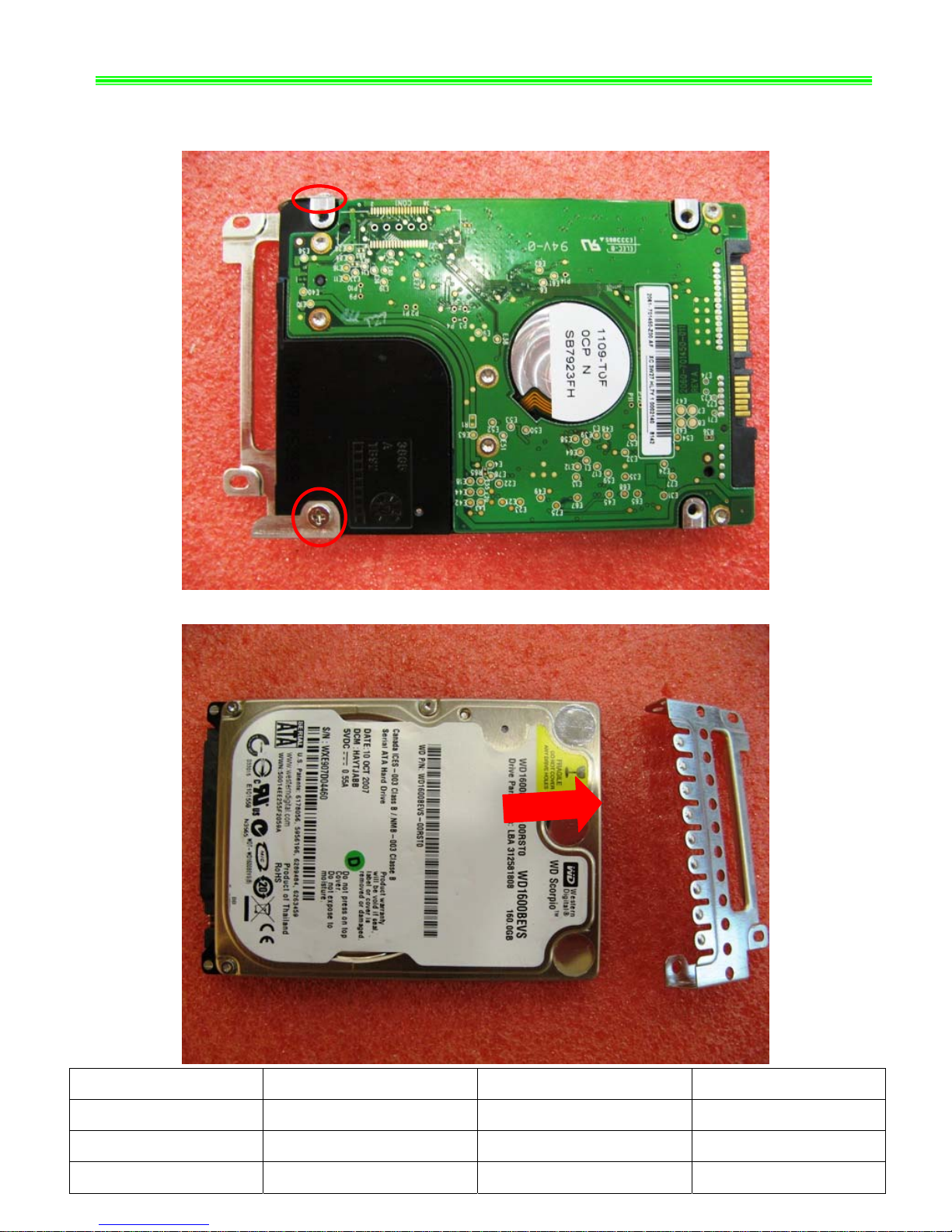
5-3:Remove 2pcs M3*3.5mm Screws, then remove HDD Bracket
as below;
Note:Screw driver torque is 1.5~2.0kgf.cm
NO. Part Name Part No. Qty
1 Screw E43-1303501-H29 2
2 HDD Bracket Assy E2M-2211511-Y28 1
3 HDD MODULE ASSY S71-2408505-W36 1
GX720(MS-1722)Disassemble SOP
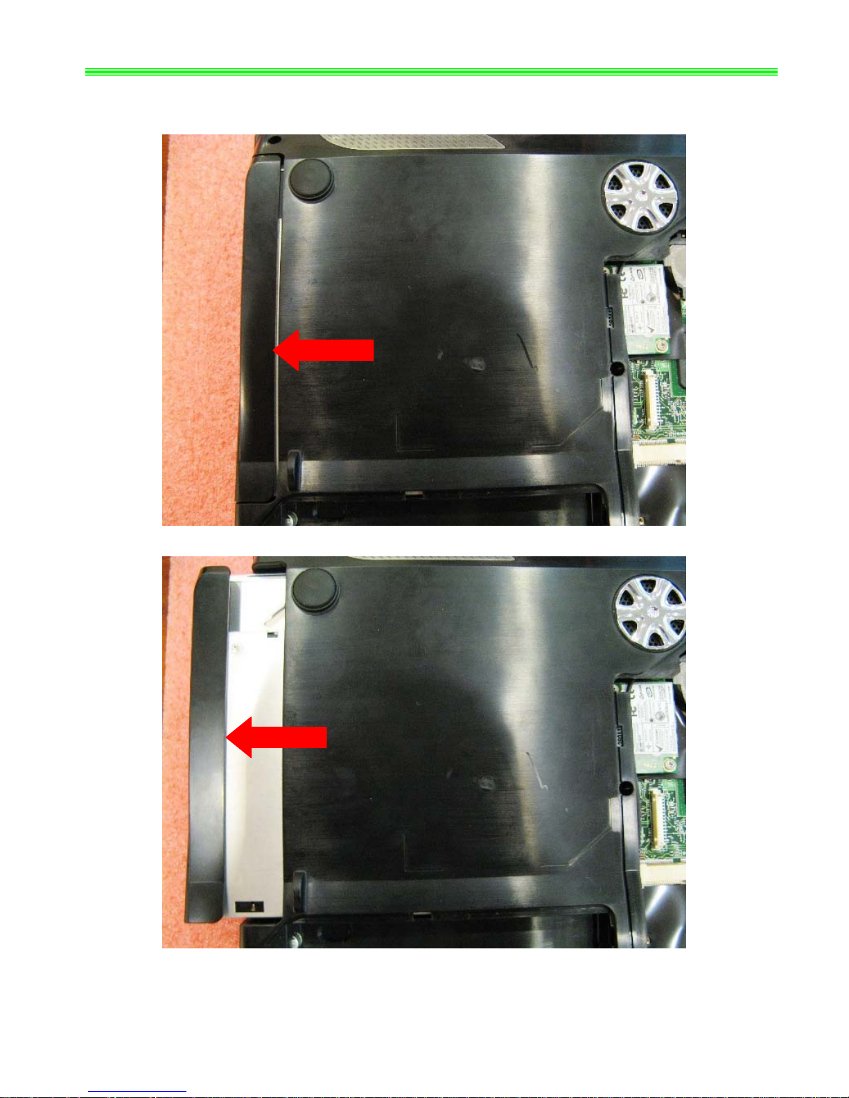
■ 6、ODD Module ASSY
6-1: Take out ODD Module Assy ;
GX720(MS-1722)Disassemble SOP
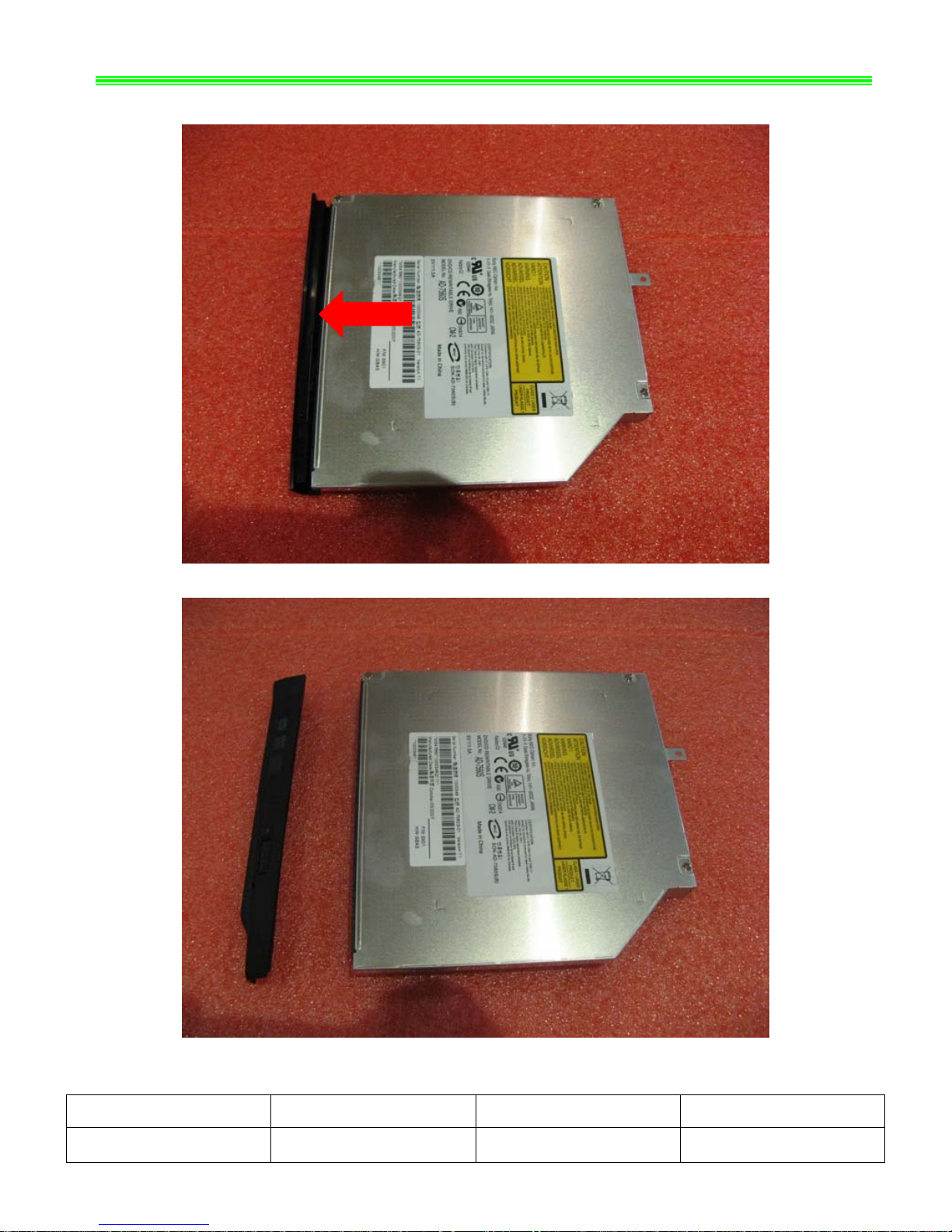
6-2:Remove ODD Bezel as below;
NO. Part Name Part No. Qty
1 ODD Bezel 307-722F112-Y31 1
GX720(MS-1722)Disassemble SOP
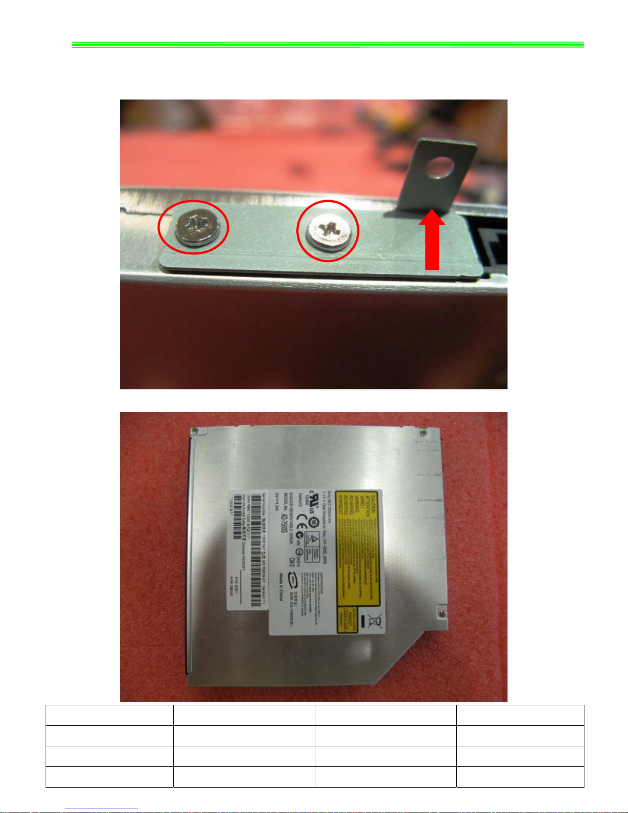
6-3:Remove 2pcs M2*3mm Screws,
Then remove ODD Bracket as below;
Note:Screw driver torque is 1.5~1.8kgf.cm
NO. Part Name Part No. Qty
1
Screw E43-1203003-H29 2
2
ODD Side Bracket E2M-2211611-Y28 1
3 ODD MODULE ASSY S7D-2270001-SI4 1
GX720(MS-1722)Disassemble SOP
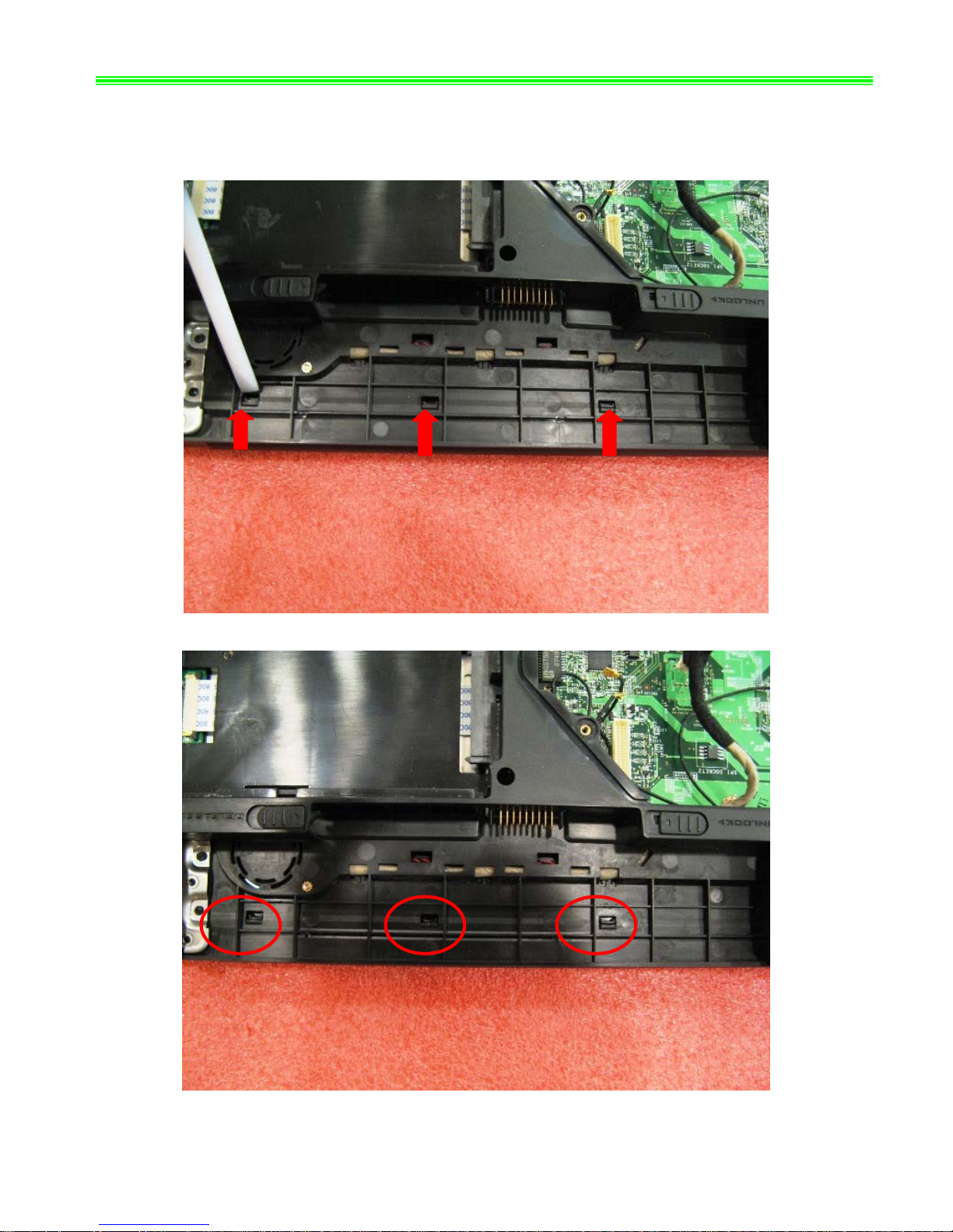
■ 7、HINGE COVER ASSY
7-1:Push Fastener as below;
 Loading...