


VR705 (MS-171F)Assemble SOP
■ 1、LCD MODULE ASSY
■ 2、LOWER CASE ASSY
■ 3、UP CASE ASSY
■ 4、HINGE COVER ASSY
■ 5、WLAN、 RAM Module
■ 6、THERMAL-KIT And CPU Module
■ 7、HDD Module ASSY
■ 8、ODD Module ASSY
■ 9、BOTTOM DOOR ASSY
■ 10、BATTERY PACK

VR705(MS-171F)Assemble SOP
■ 1、LCD MODULE ASSY
1-1:Assemble 10pcs M2*3mm screws, then assemble LCD Bracket as below;
Note:Screw driver torque is 1.5~1.8kgf.cm
NO. Part Name Part No. Qty
1 screw E43- 29 1203007-H 10
2 LCD t-R -Bracke E2M-7111111-Y28 1
3 LCD-Bracket-L E2M-7111211-Y28 1
4 LC P D BRACKET TO E2M-7111413-Y28 1
VR705(MS-171F Assemble SOP
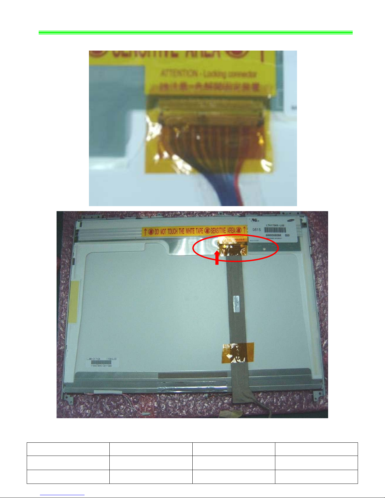
1-2:Assemble LCD LVDS Cable as b
NO. Part Name Part No. Qty
)
elow;
1 Display Module S78-230A090-CC1 1
2 LCD LVDS Cable K19-3036001-H39 1
VR 1F)Assemble SOP
NO. Part Name Part No. Qty
705(MS-17
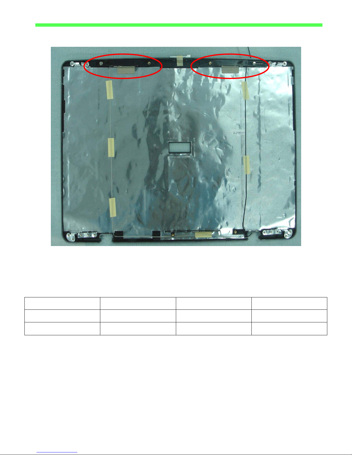
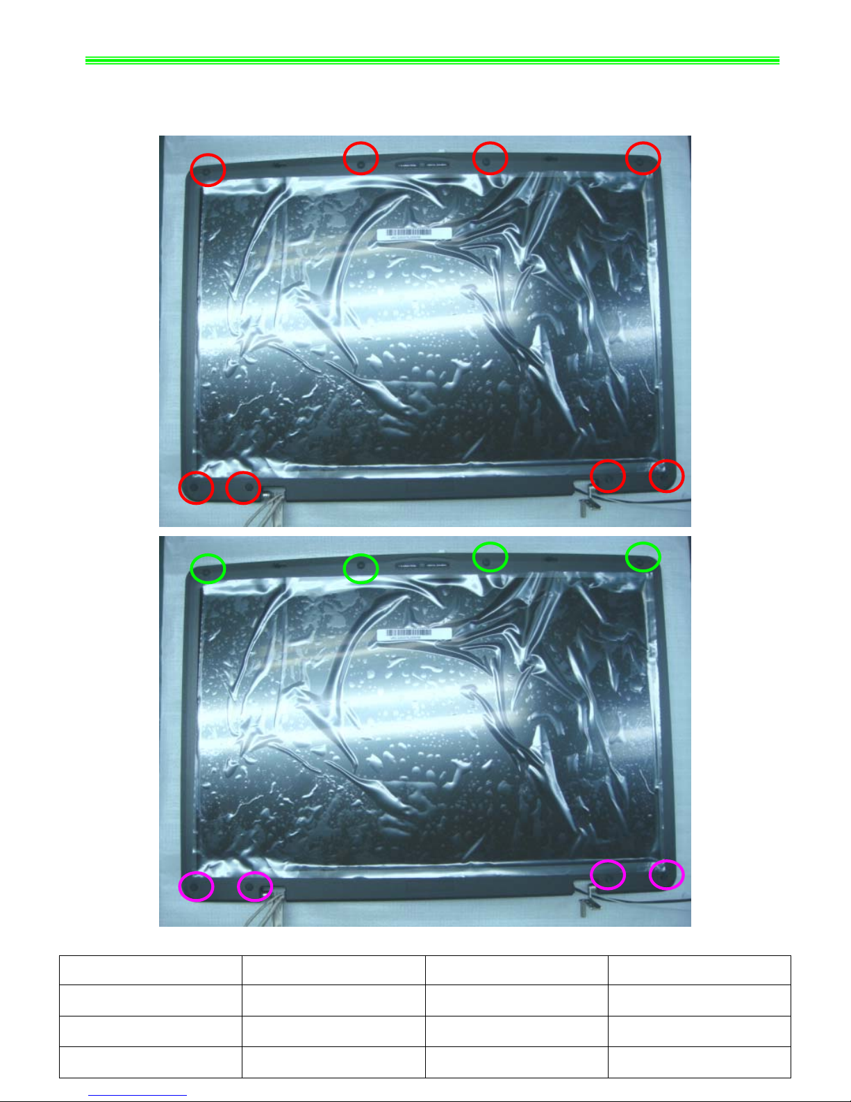
1-3:Remove WIRELISS ANTENNA as below;
1 Wire a-L S79- 39 less Antenn 1800240-H 1
2 Wireless Antenna-R S79-1800230-H39 1

VR705(MS-171F Assemble SOP
Note:Screw driver torque is 2.5~2.8kgf.cm
NO. Part Name Part No. Qty
)
1-4:Assemble 4pcs M2.5*5mm screws, then assemble Hinge_L/R as below;
1 screw E43-1255001-H29 6
2 Hinge-L E2M-7110912-G60 1
3 Hinge-R E2M-7111012-G60 1

VR70 -171F)Assemble SOP
1-5:Assemble CMOS Cab
NO. Part Name Part No. Qty
5(MS
le , then assemble CMOS Camera Module as below;
1 CMOS Camera Module S1F-0001200-AF5 1
2 C K10 03 MOS Cable -3004120-V 1
V F)Assemble SOP
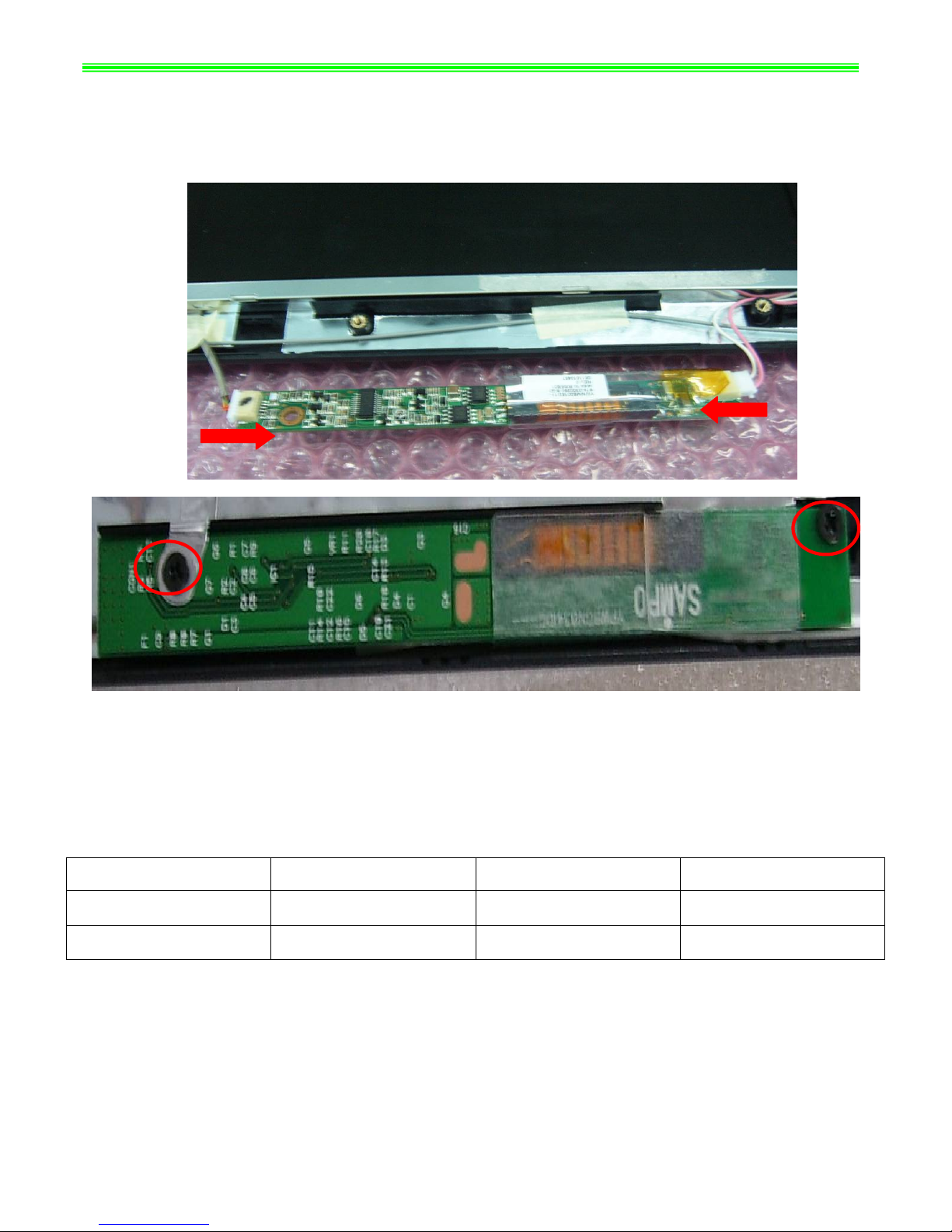
1-6:Assemble Inverter Cab rews as below;
NO. Part Name Part No. Qty
R705(MS-171
le and Display Module, then assemble 2pcs M2.5*5mm sc
Note:Screw driver torque is 1.5~2.0kgf.cm
1 screw E43-1255001-H29 2
2 Not ter S78- G3 ebook Inver 3300290-S 1

VR705(MS-171F Assemble SOP
1-7:Assemble 4pcs M2.5*5mm screws as below;
Note:Screw driver torque is 2.0~2.5kgf.cm
Part No. Qty
)
NO. Part Name
1 screw E43-1255001-H29 4
VR705(MS-171F Assemble SOP
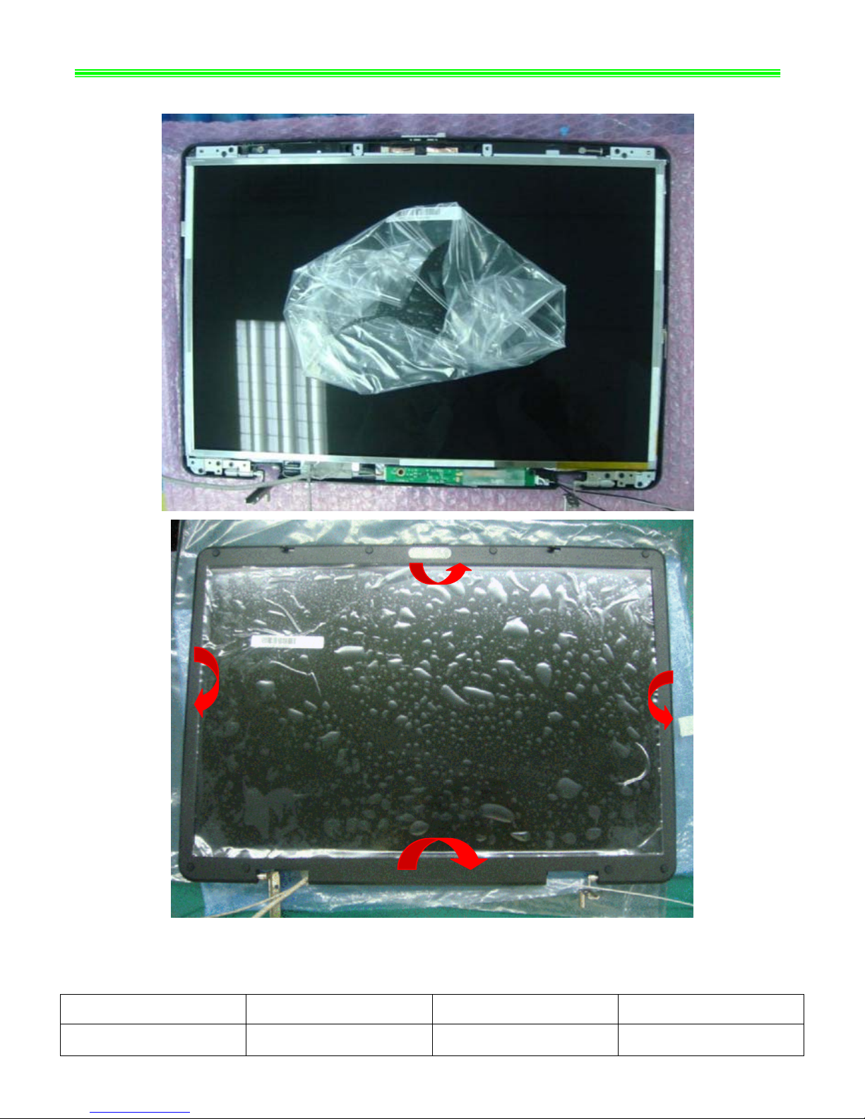
1-8:Assemble LCD Bezel as below ;
)
NO. Part Name Part No. Qty
1 LCD BEZEL E2P-711B213-SE0 1
VR705(MS-171F)Assemble SOP
1-9:Assemble 8pcs M2.5*5mm screws, then assemble 8pcs LCD Rubbers as below;
Note:Screw driver torque is 2.5~2.8kgf.cm
NO. Part Name Part No. Qty
1 LCD RUBBER E25-1035260 4 -Y40
2 LCD RUBBER E25-1035290-Y40 2
3 screw E43-I250551-H29 6
VR70 171F)Assemble SOP
■ 2、L ER CASE ASSY
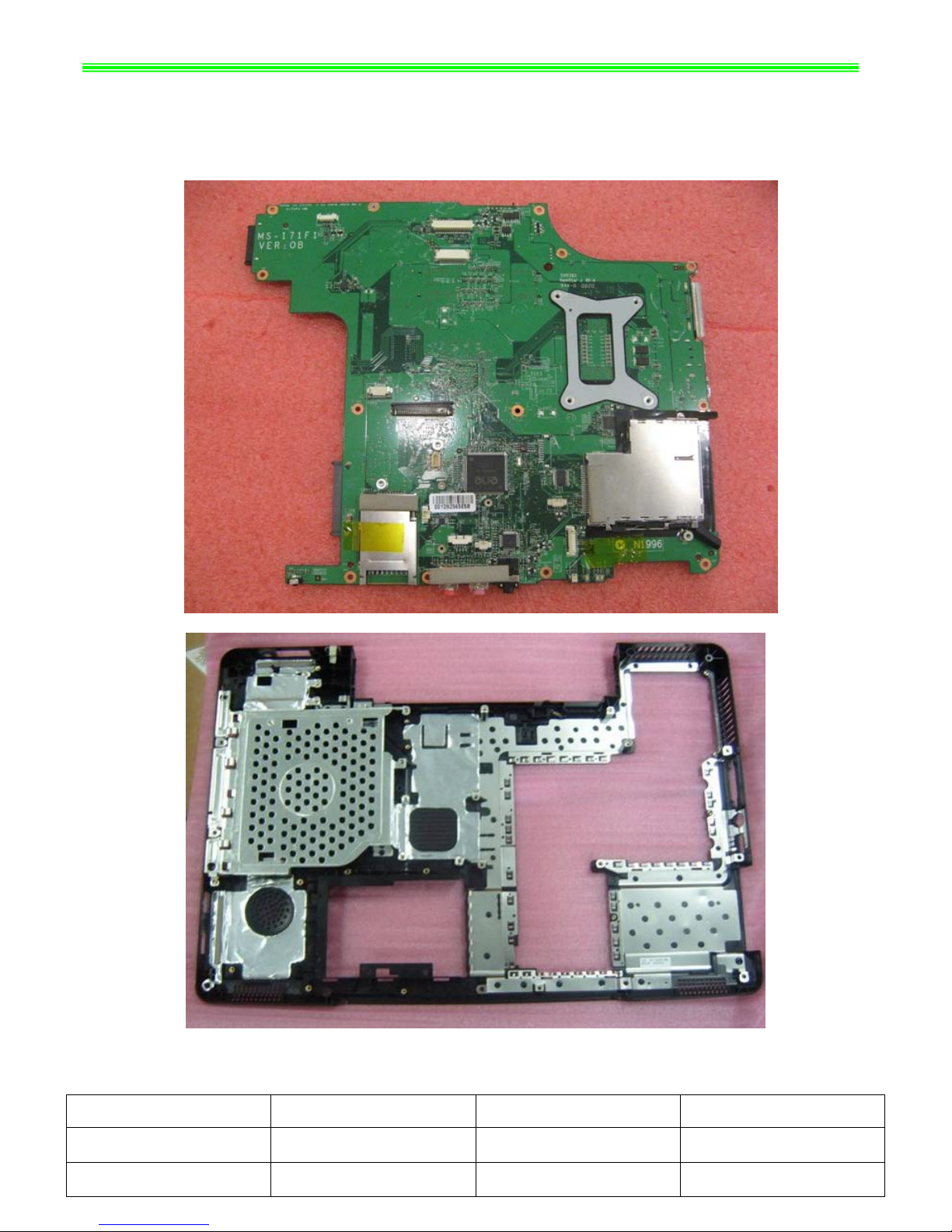
2-1 ble M/B as below;
5(MS-
OW
:Assem
Part Name Part No.
NO. Qty
1 Lower Case 307-714D422-SE0 1
2 MAIN Board 607-171F1-01S 1
VR705(MS-171F)Assemble SOP
2-2:Assemble Power Board, then assemble 1pcs M2.5*5mm screw as below;
Note driver torque is :Screw 1.5~2.0kgf.cm
NO. y
Part Name Part No. Qt
1
1 screw E43-1255001-H29 1
2 Power Board 607-171FA-B10 1
VR70 171F)Assemble SOP
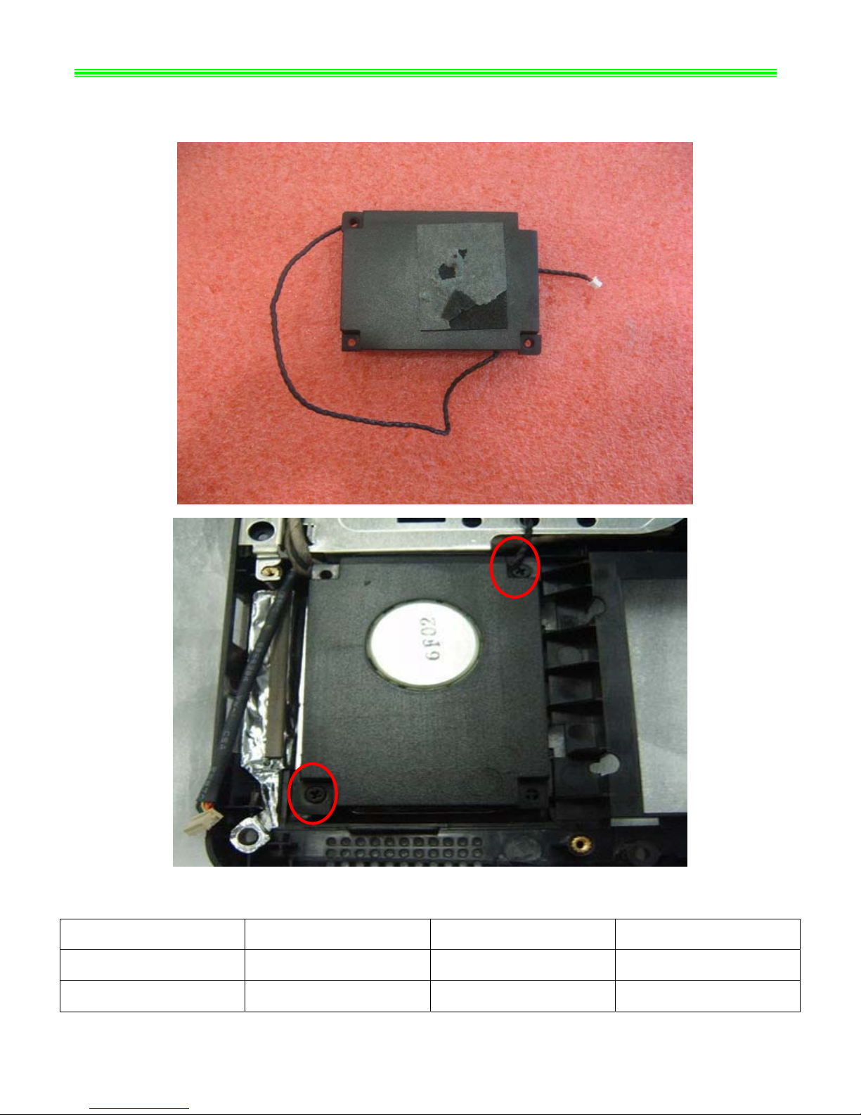
2-3:Assemble Woofer Speaker, 2pcs M2.5*5mm ;
Note:Screw driver torque is 0.8~1.0kgf.cm
5(MS-
then assemble screws as below
NO. Qty
Part Name Part No.
1 screw E43-1255001-H29 2
2 Woofer Speaker S33-2300230-SH2 1
VR705 -171F)Assemble SOP
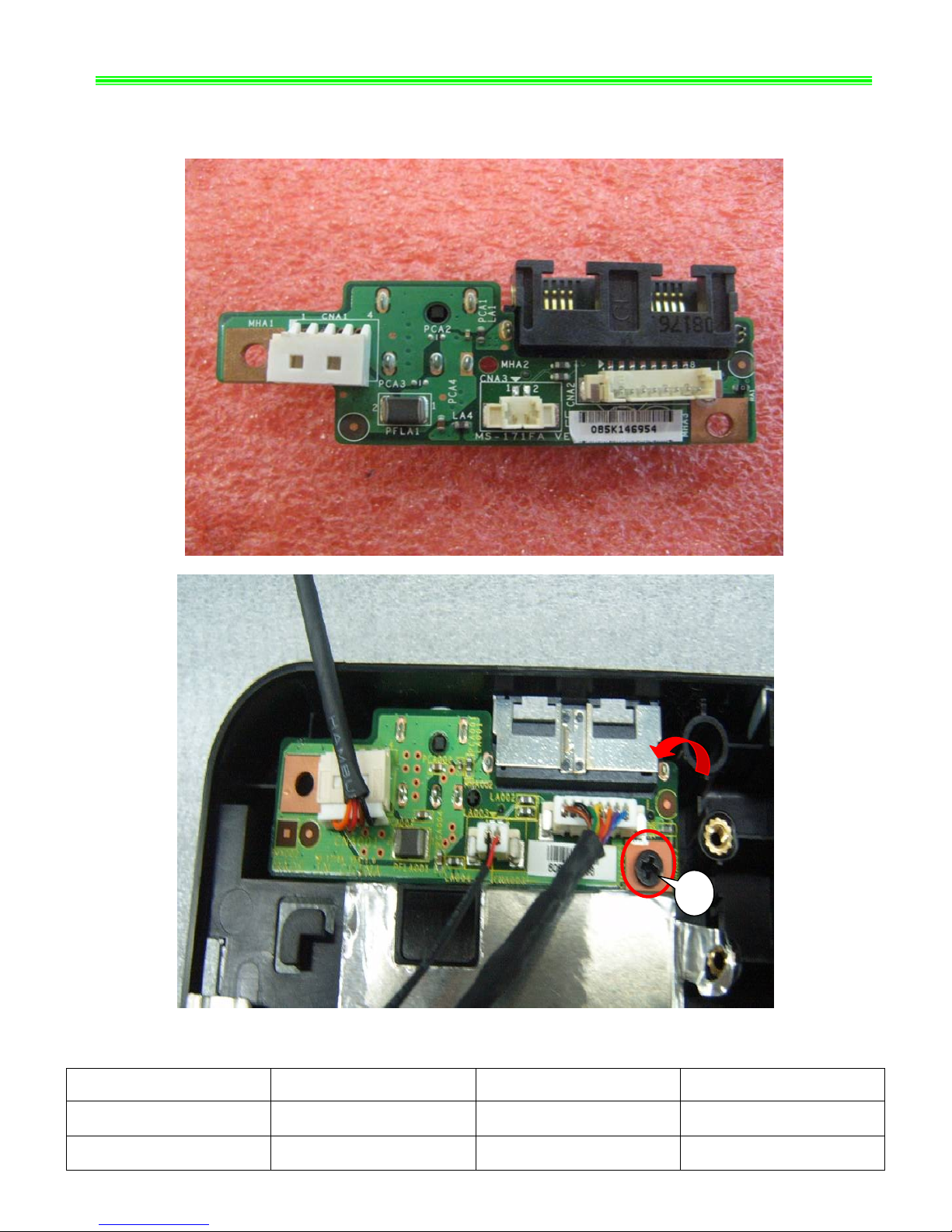
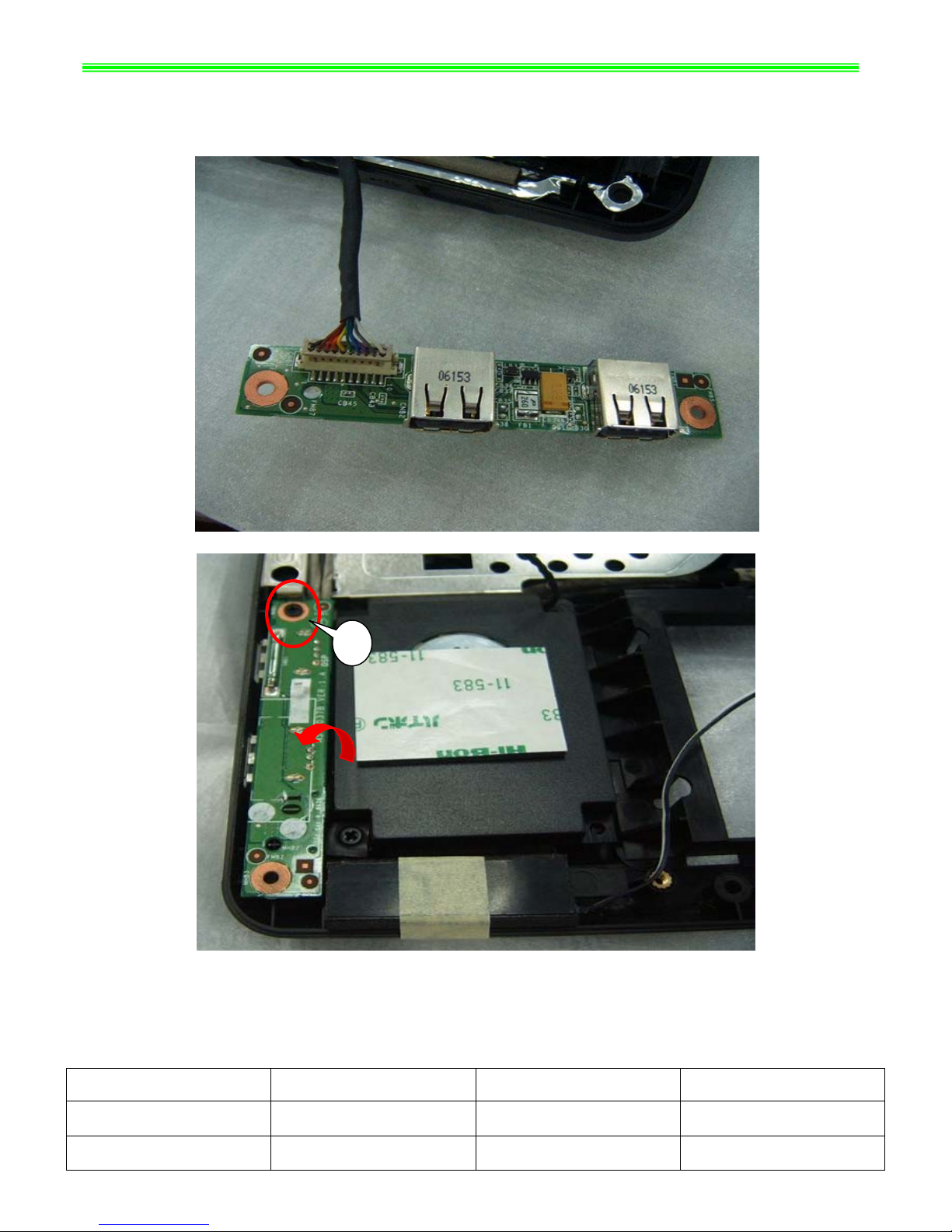
2-4:Assemble USB Board, then assemble 1pcs M2.5*5mm screw as below;
Note:Screw driver torque is 1.5~2.0kgf.cm
NO. Qty
(MS
Part Name Part No.
1
1 screw E43-1255001-H29 1
2 USB Board 607-171FB-B10 1
VR705(MS-171F Assemble SOP
2-5:Assemble DVBT board, then a M2*3mm sc
Note:Screw driver torque is 1.0~1.5kgf.cm
2-6:
Not
NO. Part Name Part No. Qty
)
ssemble 3pcs rews as below;
Assemble 1pcs M2*3mm screw as below;
e:Screw driver torque is 1.0~1.5kgf.cm
1 screw E43-1203007-H29 4
2 DVBT board S99-0000100-V03 1
3 DVBT Cover 307-7110912-SE0 1
VR705(MS-171F)Assemble SOP
2-7:Assemble 2pcs M2.5*5mm screws, then assemb l e M/B as below;
Note:Screw driver torque is 1.0~1.5kgf.cm
NO. Part Name Part No. Qty
1 screw 001-H29 2 E43-1255
2 Speaker 100-F33 1 S33-2100
VR705(MS-171F)Assemble SOP
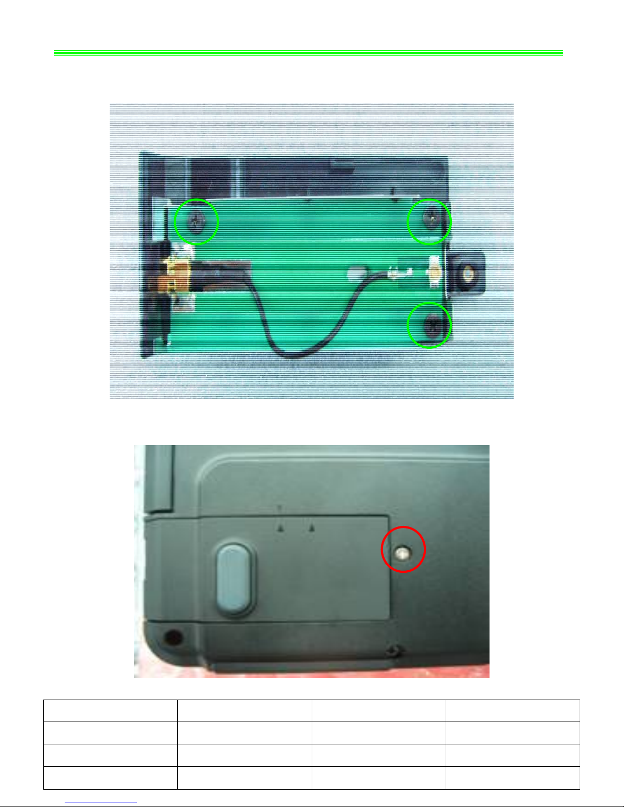
2-8:Assemble Bluetooth CABLE and ANTENNA as below;
2-9:Assemble Bluetooth, then asse 2*3mm scre
Note:Screw driver torque is 1.0~1.5kgf.cm
NO. Qty
mble 1pcs M w as below;
Part Name Part No.
1 screw E43-1203007-H29 2
2 Bluetooth 605-6837D-070 1
3 Bluetooth CABLE K10-3008058-39 1
 Loading...