

Page 1
K9N SLI/ K9N Ultra Series
MS-7250 (V2.X) Mainboard
G52-72501X4
i
Page 2

Copyright Notice
The material in this document is the intellectual property of MICRO-STAR
INTERNATIONAL. We take every care in the preparation of this document, but no
guarantee is given as to the correctness of its contents. Our products are under
continual improvement and we reserve the right to make changes without notice.
Trademarks
All trademarks are the properties of their respective owners.
NVIDIA, the NVIDIA logo, DualNet, and nForce are registered trademarks or trade-
marks of NVIDIA Corporation in the United States and/or other countries.
AMD, Athlon™ , Athlon™ XP, Thoroughbred™, and Duron™ are registered trade-
marks of AMD Corporation.
Intel® and Pentium® are registered trademarks of Intel Corporation.
PS/2 and OS®/2 are registered trademarks of International Business Machines
Corporation.
Windows® 95/98/2000/NT/XP are registered trademarks of Microsoft Corporation.
Netware® is a registered trademark of Novell, Inc.
Award® is a registered trademark of Phoenix Technologies Ltd.
AMI® is a registered trademark of American Megatrends Inc.
Revision History
Revision Revision History Date
V2.0 First release for K9N SLI/ Ultra May 2006
Technical Support
If a problem arises with your system and no solution can be obtained from the user’ s
manual, please contact your place of purchase or local distributor. Alternatively,
please try the following help resources for further guidance.
Visit the MSI website for FAQ, technical guide, BIOS updates, driver updates,
and other information: http://www.msi.com.tw/program/service/faq/
faq/esc_faq_list.php
Contact our technical staff at: http://support.msi.com.tw/
ii
Page 3
Safety Instructions
1. Always read the safety instructions carefully.
2. Keep this User’s Manual for future reference.
3. Keep this equipment away from humidity.
4. Lay this equipment on a reliable flat surface before setting it up.
5. The openings on the enclosure are for air convection hence protects the equipment from overheating. DO NOT COVER THE OPENINGS.
6. Make sure the voltage of the power source and adjust properly 110/220V before connecting the equipment to the power inlet.
7. Place the power cord such a way that people can not step on it. Do not place
anything over the power cord.
8. Always Unplug the Power Cord before inserting any add-on card or module.
9. All cautions and warnings on the equipment should be noted.
10. Never pour any liquid into the opening that could damage or cause electrical
shock.
11. If any of the following situations arises, get the equipment checked by a service
personnel:
† The power cord or plug is damaged.
† Liquid has penetrated into the equipment.
† The equipment has been exposed to moisture.
† The equipment has not work well or you can not get it work according to
User’s Manual.
† The equipment has dropped and damaged.
† The equipment has obvious sign of breakage.
12. DO NOT LEAVE THIS EQUIPMENT IN AN ENVIRONMENT UNCONDITIONED, STORAGE TEMPERATURE ABOVE 600 C (1400F), IT MAY DAMAGE THE EQUIPMENT.
CAUTION: Danger of explosion if battery is incorrectly replaced.
Replace only with the same or equivalent type recommended by the
manufacturer.
iii
Page 4

FCC-B Radio Frequency Interference Statement
This equipment has been
tested and found to comply
with the limits for a Class B
digital device, pursuant to Part
15 of the FCC Rules. These limits are designed to provide reasonable protection
against harmful interference in a residential installation. This equipment generates,
uses and can radiate radio frequency energy and, if not installed and used in accor-
dance with the instructions, may cause harmful interference to radio communications.
However, there is no guarantee that interference will not occur in a particular
installation. If this equipment does cause harmful interference to radio or television
reception, which can be determined by turning the equipment off and on, the user is
encouraged to try to correct the interference by one or more of the measures listed
below.
† Reorient or relocate the receiving antenna.
† Increase the separation between the equipment and receiver.
† Connect the equipment into an outlet on a circuit different from that to
which the receiver is connected.
† Consult the dealer or an experienced radio/television technician for help.
Notice 1
The changes or modifications not expressly approved by the party responsible for
compliance could void the user’s authority to operate the equipment.
Notice 2
Shielded interface cables and A.C. power cord, if any, must be used in order to
comply with the emission limits.
VOIR LA NOTICE D ’INSTALLATION AVANT DE RACCORDER AU RESEAU.
Micro-Star International
MS-7250
This device complies with Part 15 of the FCC Rules. Operation is subject to the
following two conditions:
(1) this device may not cause harmful interference, and
(2) this device must accept any interference received, including interference that
may cause undesired operation.
iv
Page 5
WEEE (Waste Electrical and Electronic Equipment) Statement
v
Page 6
vi
Page 7
vii
Page 8

CONTENTS
Copyright Notice.........................................................................................................ii
Trademarks..................................................................................................................ii
Revision History.........................................................................................................ii
Technical Support......................................................................................................ii
Safety Instructions...................................................................................................iii
FCC-B Radio Frequency Interference Statement.............................................iv
WEEE (Waste Electrical and Electronic Equipment) Statement.......................v
English......................................................................................................................En-1
Specifications....................................................................................................En-1
How to use this Installation Guide?.................................................................En-4
Central Processing Unit: CPU...........................................................................En-5
Memory...............................................................................................................En-6
Connectors, Jumpers, Slots.............................................................................En-7
Back Panel........................................................................................................En-13
BIOS Setup.......................................................................................................En-15
Software Information......................................................................................En-17
German....................................................................................................................De-1
Spezifikationen..................................................................................................De-1
“Wie Sie diese Installationsanleitung verwenden.” ........................................De-4
Hauptprozessor: CPU.......................................................................................De-5
Speicher.............................................................................................................De-6
Anschlüsse, Steckbrücken und Slots.............................................................De-7
Hinteres Anschlusspaneel.............................................................................De-13
BIOS Setup.......................................................................................................De-15
Software Information......................................................................................De-17
French.......................................................................................................................Fr-1
Spécificités.........................................................................................................Fr-1
“Comment utiliser ce manuel?” ..........................................................................Fr-4
Central Processing Unit: CPU............................................................................Fr-5
Mémoire...............................................................................................................Fr-6
Connecteurs, Jumper, Slots..............................................................................Fr-7
Panneau Arrière...............................................................................................Fr-13
Installation du BIOS..........................................................................................Fr-15
Information de Logiciel.....................................................................................Fr-17
viii
Page 9
Installation Guide
Specifications
Processor Support*
- AMD® Athlon 64 X2, Athlon 64, Athlon FX and Sempronin the socket AM2 package.
Supported FSB
- HyperTransport supporting speed up to 1GHz (2000MT/s)
Chipset
- nVIDIA® nForce 570 SLI (MCP55P) / nForce 570 (MCP55 Ultra) chipset
Memory Support**
- DDRII 533/667/800 SDRAM (8GB Max)
- 4 DDRII DIMMs (Dual Channel, 240-pin/ 1.8V)
LAN
- Supports Dual LAN 10/100/1000 Fast Ethernet by Vitesse VSC8601
IEEE 1394 (optional)
- Controlled by VIA® VT6307
- Transfer rate is up to 400 Mb/s
Audio
- Controlled by Realtek ALC883
- Supports 7.1 channels audio out
- Azalis 1.0 Audio solution
IDE
- 1 IDE port controlled by nForce 570 SLI/ nForce 570
- Supports Ultra DMA 133/100/ 66 mode, and PIO Bus Master mode
SATA
- 6 SATAII ports (SATA1~6, 300 MB/s) controller by nForce 570 SLI/ nForce 570
RAID
- SATA1~6 support RAID0/ RAID1/ RAID0+1/ RAID5 or JBOD mode
Floppy
- 1 floppy port
Connectors
Back panel
- 1 PS/2 mouse port
- 1 PS/2 keyboard port
- 1 serial port
- 1 parallel port
- 1 IEEE 1394 port (optional)
- 1 Coaxial SPDIF out jack
- 4 USB 2.0 ports
- 2 LAN jacks
- 5 flexible audio jacks
- 1 Optical fiber SPDIF out jack
On-Board Pinheaders
- 1 D-Bracket 2 pinheader
- 1 IrDA pinheader
- 3 USB 2.0 pinheaders
- 1 IEEE 1394 pinheader (optional)
Slots
For K9N SLI series
- 2 PCI Express x 16 slots (support SLI Technology)
SLI mode - Both PCIE x 16 slots are compatible with PCI Express x 8 speed
Non SLI mode - PCI_E1 slot is compatible with PCI Express x16 speed, and the PCI_E2 slot is compatible with
PCI Express x 8 speed.
- 2 PCI Express x 1 slots
- 3 PCI slots includes one orange slot which supports 2 master for MSI special PCI function card (ex. wireless LAN
and bluetooth combo card.).
For K9N Ultra series
- 1 PCI Express x 16 slot
- 3 PCI Express x 1 slots
- 3 PCI slots includes one orange slot which supports 2 master for MSI special PCI function card (ex. wireless LAN
and bluetooth combo card.).
Form Factor
- ATX (24.5 cm X 30.5 cm)
Mounting
- 9 mounting holes
*For the latest information about CPU, please visit http://www.msi.com.tw/program/products/mainboard/mbd/
pro_mbd_cpu_support.php
**For the updated supporting memory modules, please visit http://www.msi.com.tw/program/products/mainboard/mbd/
pro_mbd_trp_list.php
English
En-1
Page 10
MS-7250 Mainboard
nvidia
MCP55P
(Optional)
(Optional)
30
35
4138
37
29
34
(optional)
43
31
39
36
40
44
23
4
25
1
3
15
16
5
21
6
4
7
26
En-2
122714
10
Layout of K9N SLI Series
(MS-7250 v2.X) Mainboard
20
8
9
19
Page 11
Installation Guide
nvidia
MCP55Ultra
(Optional)
(Optional)
30
35
29
34
(optional)
43
31
36
4138
39 44
37
English
40
23
4
25
1
3
15
16
5
21
6
4
7
26
122714
10
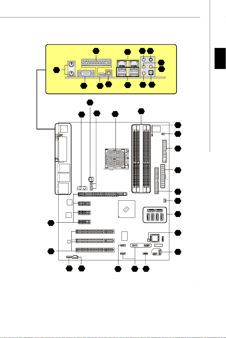
Layout of K9N Ultra Series
(MS-7250 v2.X) Mainboard
20
8
9
19
En-3
Page 12
MS-7250 Mainboard
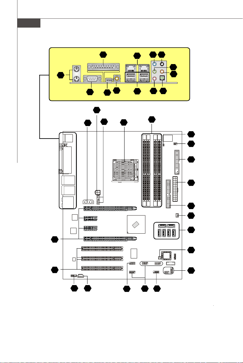
“ How to use this Installation Guide?”
This installation guide is designed for you to easily install the mainboard. Follow the steps below to use this guide:
- Read the specifications of the mainboard first on page En-1.
- Find out the component with the component number at your desire from the layout of the mainboard on page En-2.
- Find out the component description and installing instructions with the “Components Index Table” direction and install
it.
- Set BIOS and install the driver / utiltity at your desire.
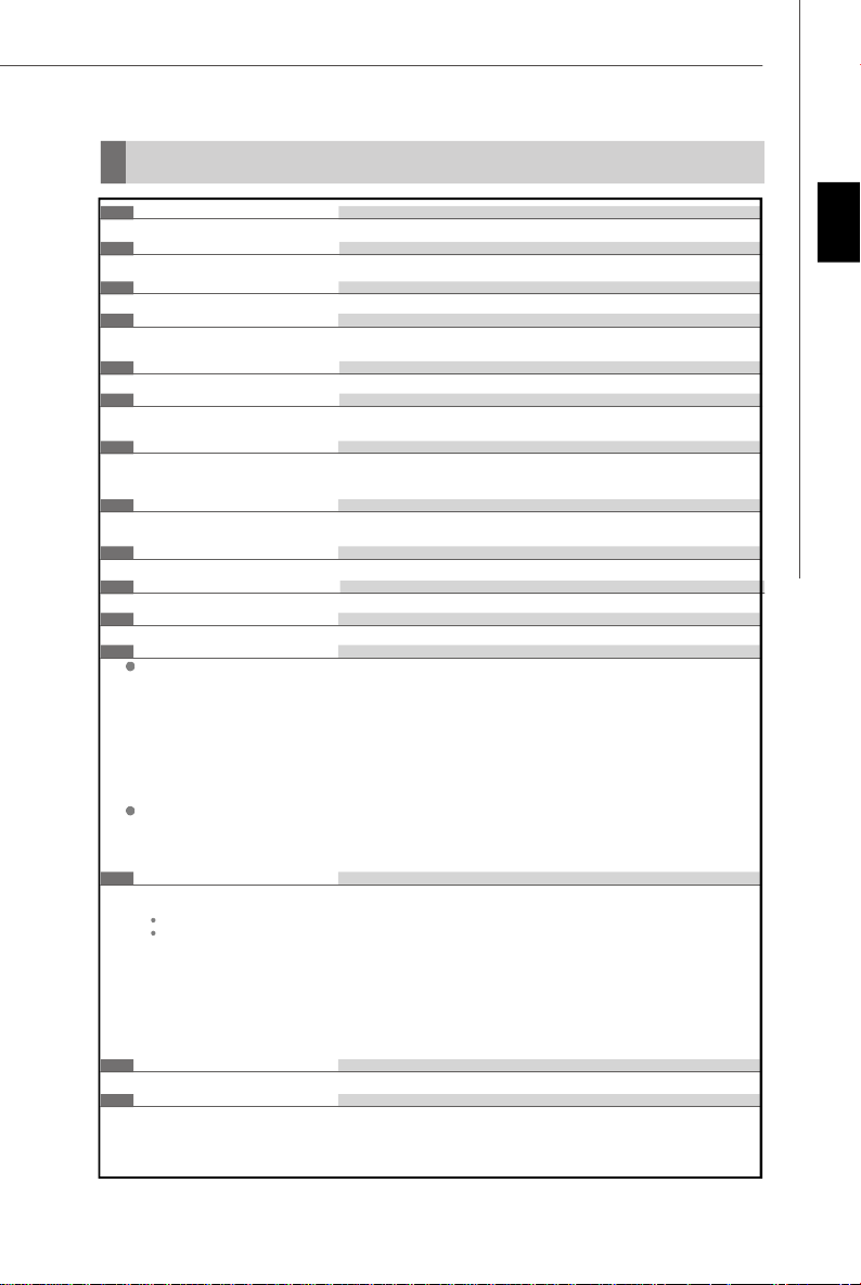
Components Index Table
Component Number Component Numberpage page
Central Processing Unit Socket En-4 DDRII Sockets : DIMM1~4 (dual channel)En-5
1
Fan Power Connectors En-6 Floppy Disk Driver Connector En-6
4
ATA 133 Hard Disk Connector En-6 Serial ATA 2.0 Connectors En-6
6
Front Panel Connectors En-7 Front USB 2.0 Connectors En-7
8
IEEE 1394 Connectors En-7 Front Panel Audio Connector En-8
10
14 15
CD-In Connector En-8 Chassis Intrusion Switch Connector En-8
16
IrDA Infrared Module Connector En-8 D-BracketTM 2 Connector En-9
Clear CMOS Button En-10 ATX 24-Pin Power Connector En-10
20
ATX 12V Power Connector (2x2-Pin) En-10 ATX 12V Power Connector (1x4-Pin) En-10
23
26
PCI Express Slots (x16/ x4/ x1) En-11 PCI Slots En-11
29
Mouse/ Keyboard port Connector En-12 Parallel Port Connector En-12
Serial Port Connector En-12 IEEE 1394 Port Connector En-12
31 34
LAN (RJ-45) Jack En-13 USB Connectors En-13
35
37
Green Audio Jack (Line-out) En-13 Blue Audio Jack En-13
Pink Audio Jack (Mic-In) En-13 Orange Audio Jack En-13
39
41 43
Black Audio Jack (Rear Surround-Out) En-13 Coaxial S/PDIF-out Connector En-13
44
Optical S/PDIF-out Connector En-13
3
5
7
9
12
19
21
25
27
30
36
38
40
En-4
Page 13
Installation Guide
Correct CPU
Central Processing Unit: CPU
1
The mainboard supports AMD® processor. The mainboard uses a CPU socket called Socket AM2 for easy CPU
installation.
For the latest information about CPU, please visit http://www.msi.com.tw/program/products/mainboard/mbd/
pro_mbd_cpu_support.php
Important
Overheating
Overheating will seriously damage the CPU and system, always make sure the cooling fan can work properly to protect
the CPU from overheating.
Replacing the CPU
While replacing the CPU, always turn off the ATX power supply or unplug the power supply’s power cord from grounded
outlet first to ensure the safety of CPU.
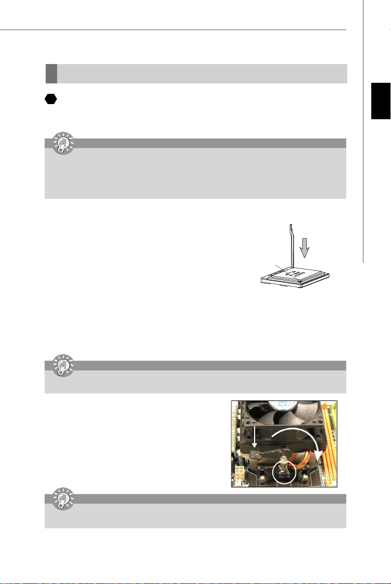
CPU Installation Procedures for Socket AM2
1. Please turn off the power and unplug the power cord before installing the CPU.
2. Pull the lever sideways away from the socket. Make sure to raise the lever up to a
90-degree angle.
3. Look for the gold arrow of the CPU. The gold arrow should point as shown in the
picture. The CPU can only fit in the correct orientation.
4. If the CPU is correctly installed, the pins should be completely embedded into the
socket and can not be seen. Please note that any violation of the correct installation
procedures may cause permanent damages to your mainboard.
5. Press the CPU down firmly into the socket and close the lever. As the CPU is likely
to move while the lever is being closed, always close the lever with your fingers
pressing tightly on top of the CPU to make sure the CPU is properly and completely
embedded into the socket.
Installing CPU Cooler Set
When you are installing the CPU, make sure the CPU has a heat sink and a cooling fan attached on the top to
prevent overheating. If you do not have the heat sink and cooling fan, contact your dealer to purchase and install them
before turning on the computer.
Gold arrow
placement
English
Important
Mainboard photos shown in this section are for demonstration of the cooler installation for Socket AM2 CPUs only. The
appearance of your mainboard may vary depending on the model you purchase.
1. Position the cooling set onto the retention mechanism. Hook one end
of the clip to hook first.
2. Then press down the other end of the clip to fasten the cooling set on
the top of the retention mechanism. Locate the Fix Lever and lift up it
.
3. Fasten down the lever.
4. Attach the CPU Fan cable to the CPU fan connector on the mainboard.
Important
While disconnecting the Safety Hook from the fixed bolt, it is necessary to keep an eye on your fingers, because once
the Safety Hook is disconnected from the fixed bolt, the fixed lever will spring back instantly.
Fixed Lever
En-5
Page 14
MS-7250 Mainboard
Memory
2
DDR
Specification : 184-pin, 2.5v.
Single channel definition : All DIMM slots are GREEN color.
Dual channels definition : DIMM slot(s) on Channel A are marked in GREEN color. DIMM slot(s) on Channel B are
3
DDRII
Specification : 240-pin, 1.8v.
Single channel definition : All DIMM slots are GREEN color.
Dual channels definition : DIMM slot(s) on Channel A are marked in GREEN color. DIMM slot(s) on Channel B are
-DDRII modules are not interchangeable with DDR and the DDRII standard is not backward compatible, you should
always install DDRII memory module in the DDRII DIMM slot and install DDR memory module in the DDR DIMM slot.
- In dual-channel mode, make sure that you install memory modules of the same type and density in different
channel DDR DIMM slots.
- To enable successful system boot-up, always insert the memory modules into the DIMM1 first.
marked in Purple color.
40x2=80 pin 52x2=104 pin
marked in Orange color.
64x2=128 pin 56x2=112 pin
Important
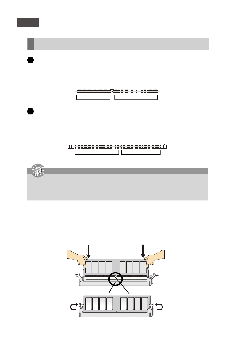
Installing DDR/ DDRII Modules
You can find the notch on the memory modules and the volt on the DIMM slots whether DDR or DDRII. Follow the procedures
below to install the DDR/ DDRII module properly.
1. The DDR/DDRII modules has only one notch on the center of module. The module will only fit in the right orientation.
2. Insert the memory module vertically into the DIMM slot. Then push it in until the golden finger on the memory module
is deeply inserted in the socket.
3. The plastic clip at each side of the DIMM slot will automatically close.
Volt
Notch
En-6
Page 15
Installation Guide
Connectors, Jumpers, Slots
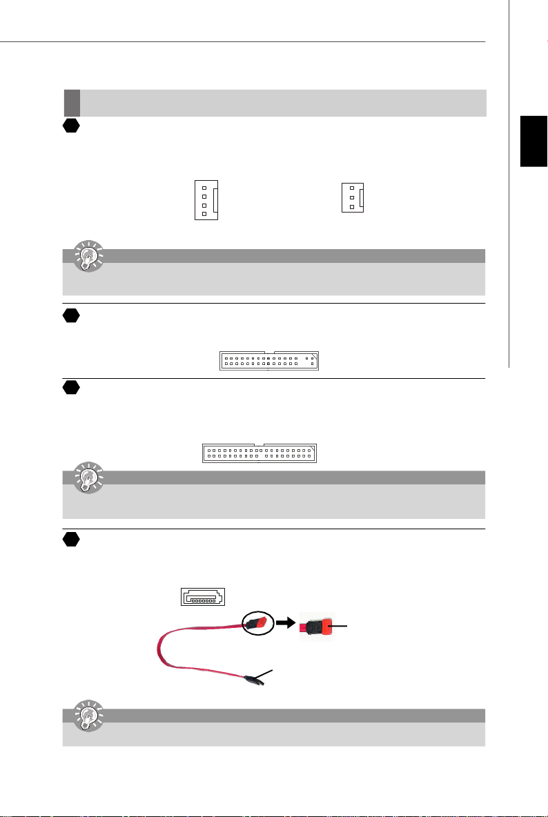
4
Fan Power Connectors
The fan power connectors support system cooling fan with +12V. The CPU FAN supports Smart FAN function. When
connect the wire to the connectors, always take note that the red wire is the positive and should be connected to the +12V,
the black wire is Ground and should be connected to GND. If the mainboard has a System Hardware Monitor chipset onboard, you must use a specially designed fan with speed sensor to take advantage of the fan control.
Control
SENSOR
+12V
GND
CPU FAN
Important
Please refer to the recommended CPU fans at AMD® official website or consult the vendors for proper CPU cooling fan.
Fan/heatsink with 3 or 4 pins are both available for CPUFAN.
5
Floppy Disk Drive Connector (FDD connector)
The mainboard provides a standard floppy disk drive connector that supports 360K, 720K, 1.2M, 1.44M and 2.88M floppy
disk types.
6
ATA133 Hard Disk Connector (IDE connector)
A IDE connector can connect a Master and a Slave drive. You can connect CD-ROM/ Hard Driver and other IDE devices.
The Ultra ATA133 interface boosts data transfer rates between the computer and the hard drive up to 133 megabytes (MB)
per second. The new interface is one-third faster than earlier record-breaking Ultra ATA/100 technology and is backwards
compatible with the existing Ultra ATA interface.
SENSOR or NC
+12V
GND
SYS FAN/ NB FAN/
POWER FAN
English
Important
If you install two hard disks on cable, you must configure the second drive to Slave mode by setting its jumper. Refer
to the hard disk documentation supplied by hard disk vendors for jumper setting instructions.
Serial ATA Connector
7
SATA1.0 connector supports serial ATA data rates of 150 MB/s and will be marked in ORANGE color. SATA 2.0 connector
supports serial ATA data rates of 300 MB/s and will be marked in PURPLE color. Each SATA connector can connect to 1
hard disk device.
SATA 1.0 connector (Orange)
SATA 2.0 connector (Purple)
Serial ATA cable
Connect to SATA connector
Important
Please do not fold the Serial ATA cable into 90-degree angle. Otherwise, data loss may occur during transmission.
Take out the dust cover and connect
to the hard disk devices
En-7
Page 16
MS-7250 Mainboard
8
Front Panel Connectors
These two front panel connectors are used for electrical connection to the front panel switches and LEDs. JFP1 is compliant
with Intel® Front Panel I/O Connectivity Design Guide.
Power
Power
LED
Switch
2
JFP1
1
HDD
LED
9
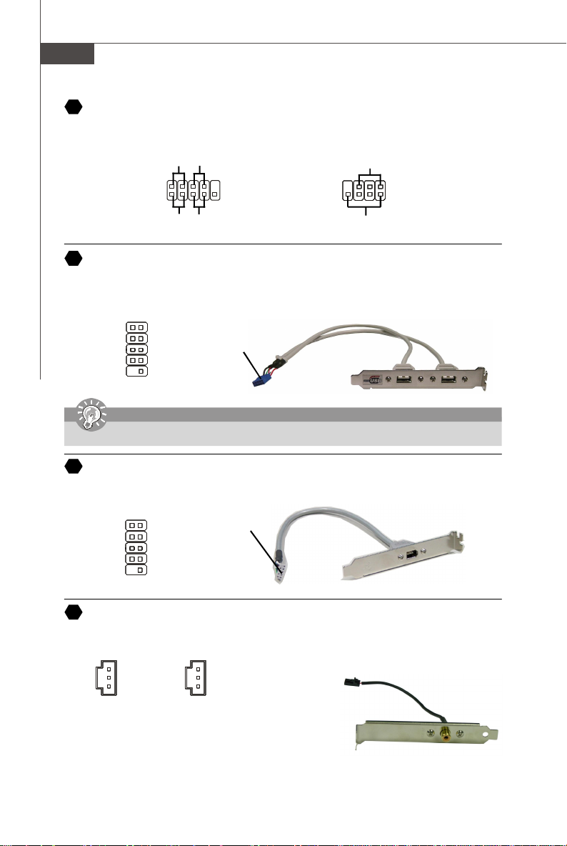
Front USB 2.0 Connector (Yellow)
USB 2.0 technology increases data transfer rate up to a maximum throughput of 480Mbps, which is 40 times faster than
USB 1.1, and is ideal for connecting high-speed USB interface peripherals such as USB HDD, digital cameras, MP3
players, printers, modems and the like.
1 2
VCC
USB0-
USB0+
GND
Key (no pin)
Note that the pins of VCC and GND must be connected correctly to avoid possible damage.
10
IEEE 1394 Connector (Green)
The 1394 pin header allows you to connect IEEE 1394 ports via an external IEEE1394 bracket.
TPA+
Ground
TPB+
Cable power
Key (no pin)
10
9
Important
1 2
9 10
VCC
USB1USB1+
GND
USBOC
TPAGround
TPBCable power
Ground
10
9
Reset
Switch
Connected to USB
connector
Connected to 1394
connector (with foolproof design)
Power LED
7
8
Speaker
1
JFP2
2
USB 2.0 Bracket
(Optional)
IEEE1394 Bracket
(Optional)
11
SPDIF-Out Connector/ SPDIF-In Connector
These two connectors are used to connect SPDIF (Sony & Philips Digital Interconnect Format) interface for digital audio
transmission.
Connected to SPDIF-out/
GND
SPDIF_out
VCC
SPDIF_Out
SPDIF_In
GND
SPDIF_in
VCC
SPDIF-in connector
SPDIF Bracket (Optional)
En-8
Page 17
Installation Guide
12
Front Panel Audio Connector
The front panel audio connector allows you to connect to the front panel audio and
is compliant with Intel® Front Panel I/O Connectivity Design Guide.
2
1
910
Important
AUD_GND
AUD_VCC
AUD_RET_R
Key
AUD_RET_L
Front Panel Audio Connector
13
The front panel audio connector allows you to connect to the front panel audio and
is compliant with Intel® Front Panel I/O Connectivity Design Guide.
GND R
L
CINTRU
1
GND
2
2
1
NC
NC
DCD
SIN
SOUT
DTR
Ground
IRRX
6
5
156
DSR
RTS
CTS
RI (9)
VCC5
IRTX
Ground
AUD_MIC
AUD_MIC_BIAS
AUD_FPout_R
HP_ON
AUD_FPout_L
If you do not want to connect to the front audio header, pins 5 & 6, 9 & 10 have to be jumpered in order to have signal output
directed to the rear audio ports. Otherwise, the Line-Out connector on the back panel will not function.
CD-In Connector
14
This connector is provided for CD-ROM audio.
15
Chassis Intrusion Switch Connector
This connector is connected to a 2-pin chassis switch. If the chassis is opened, the switch will be short. The system will
record this status and show a warning message on the screen. To clear the warning, you must enter the BIOS utility and
clear the record.
IrDA Infrared Module Connector
16
The connector allows you to connect to IrDA Infrared module. You must configure the setting through the BIOS setup to use
the IR function. It is compliant with Intel® Front Panel I/O Connectivity Design Guide.
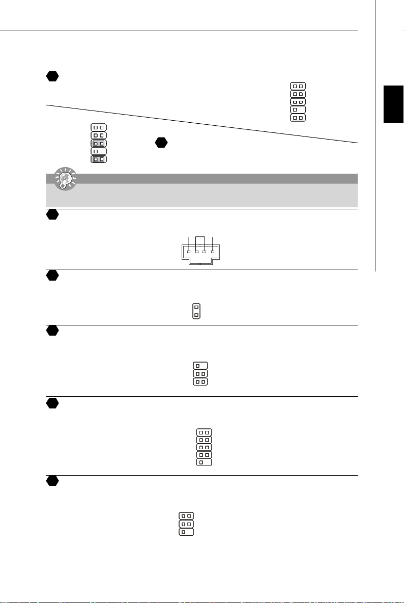
17
Serial Port Header
The 9-pin header allows you to connect serial port via an external COM port bracket.
port1 _L
port1 _R
port2_R
Sense_Send
port2_L
2
1
Ground
Presence#
Sense1_Return
Key
Sense2_Return
910
English
18
TV-Out Connector
The TV-Out connector is for you to attach a TV-Out bracket. The TV-Out bracket offers some types of TV-Out connectors.
Select the appropriate one to connect to an television and it will be able to display PC information.
Ground
Yout
Cout
1 4
3
COMP or CVBS
Ground (5)
En-9
Page 18

MS-7250 Mainboard
D-Bracket™ 2 Connector
19
The connector is for you to connect D-Bracket™ 2. D-Bracket™ 2 is a external USB Bracket that support both USB1.1 &
2.0 spec. It integrates four LEDs and allows users to identify system problem through 16 various combinations of LED
signals. The 4 LEDs can debug all problems that fail the system, such as VGA, RAM or other failures. This special feature
is very useful for the overclocking users. These users can use the feature to detect if there are any problems or failures.
D-Bracket™ 2
(Optional)
1 2
LEDs
3 4
DBG1
DBG2
DBG3
DBG4
Key(no pin)
1
9
2
10
Connected to D-Bracket™
2 Connector
DBR1
DBR2
DBR3
DBR4
NC
Connected to the USB pinheader
in YELLOW color
Red
LEDs signal
1 2
3 4
1 2
3 4
1 2
3 4
1 2
3 4
1 2
3 4
1 2
3 4
1 2
3 4
Green
Description
System Power ON
The D-LED will hang here if the
processor is damaged or not installed properly.
Early Chipset Initialization
Memory Detection Test
Testing onboard memory size. The
D-LED will hang if the memory module is damaged or not installed
properly.
Decompressing BIOS image to RAM
for fast booting.
Initializing Keyboard Controller.
Testing VGA BIOS
This will start writing VGA sign-on
message to the screen.
Processor Initialization
This will show information regarding
the processor (like brand name, system bus, etc...)
1 2
3 4
1 2
3 4
1 2
3 4
1 2
3 4
1 2
3 4
1 2
3 4
1 2
3 4
DescriptionLEDs signal
Initializing Video Interface
This will start detecting CPU clock,
checking type of video onboard. Then,
detect and initialize the video adapter.
BIOS Sign On
This will start showing information
about logo, processor brand name,
etc...
Testing Base and Extended Memory
Testing base memory from 240K to
640K and extended memory above
1MB using various patterns.
Assign Resources to all ISA.
Initializing Hard Drive Controller
This will initialize IDE drive and
controller.
Initializing Floppy Drive Controller
This will initialize Floppy Drive and
controller.
Boot Attempt
This will set low stack and boot via
INT 19h.
En-10
1 2
3 4
Testing RTC (Real Time Clock)
1 2
3 4
Operating System Booting
Page 19

Installation Guide
Clear CMOS Button
20
The CMOS RAM onboard has a power supply from external battery to keep the data of system configuration. With the CMOS
RAM, the system can automatically boot OS every time it is turned on. If you want to clear the system configuration, use the
Clear CMOS Button to clear data. Press the button in the middle of the connector top side to clear the data.
Important
Make sure that you power off the system before clearing CMOS data.
English
Power Supply Attachment
Before inserting the power supply connector, always make sure that all components
are installed properly to ensure that no damage will be caused. All power connectors
on the mainbnoard have to connect to the ATX power supply and have to work together to ensure stable operation of the mainboard.
21
ATX 24-Pin Power Connector
This connector allows you to connect an ATX 24-pin power supply. To connect the ATX
24-pin power supply, make sure the plug of the power supply is inserted in the proper
orientation and the pins are aligned. Then push down the power supply firmly into the
connector.
1020
12V 5V
5VSB
PWR OK
GND
5V
GND
5V
GND
3.3V
3.3V
ATX 12V Power Connector (2x2-Pin)
23
These 12V power connectors is used to provide power to the CPU.
24
ATX 12V Power Connector (2x4-Pin)
These 12V power connectors is used to provide power to the CPU.
ATX 12V Power Connector (1x4-Pin)
25
These 12V power connectors is used to provide power to the graphics card.
5V
-5V
GND
GND
GND
PS-ON
GND
-12V
3.3V
1
11
22
ATX 20-Pin Power Connector
This connector allows you to connect an ATX 20-pin power supply. To connect the ATX
20-pin power supply, make sure the plug of the power supply is inserted in the proper
orientation and the pins are aligned. Then push down the power supply firmly into the
connector.
GND
12V
+12V
+12V
+12V
+12V
1224
+3.3V
+12V
+12V
5VSB
PWR OK
GND
+5V
GND
+5V
GND
+3.3V
+3.3V
1
2
GND
12V
34
1
5
GND
GND
GND
GND
8 4
1
2
3
4
5V
GND
GND
12V
GND
+5V
+5V
+5V
NC
GND
GND
GND
PS-ON#
GND
-12V
+3.3V
1
13
En-11
Page 20

MS-7250 Mainboard
PCI Express Slots (x16/ x4/ x1)
26
The PCI Express slot, as a high-bandwidth, low pin count, serial, interconnect technology. PCI Express architecture
provides a high performance I/O infrastructure for Desktop Platforms with transfer rates starting at 2.5 Giga transfers per
second over a PCI Express x1 lane for Gigabit Ethernet, TV Tuners, 1394 controllers, and general purpose I/O. Also,
desktop platforms with PCI Express Architecture will be designed to deliver highest performance in video, graphics,
multimedia and other sophisticated applications. Moreover, PCI Express architecture provides a high performance graphics infrastructure for Desktop Platforms doubling the capability of existing AGP8x designs with transfer rates of 4.0 GB/
s over a PCI Express x16 lane for graphics controllers. You can insert the expansion cards to meet your needs. When adding
or removing expansion cards, make sure that you unplug the power supply first.
PCI Express x 16 Slot
PCI Express x 4 Slot
PCI Express x 1 Slot
27
PCI (Peripheral Component Interconnect) Slot
The PCI slots allow you to insert the expansion cards to meet your needs. When adding or removing expansion cards, make
sure that you unplug the power supply first. Meanwhile, read the documentation for the expansion card to make any necessary
hardware or software settings for the expansion card, such as jumpers, switches or BIOS configuration.
AGP (Accelerated Graphics Port) Slot
28
The AGP slot allows you to insert the AGP graphics card. AGP is an interface specification designed for the throughput
demands of 3D graphics. It introduces a 66MHz, 32-bit channel for the graphics controller to directly access main memory.
En-12
Page 21

Installation Guide
1
24
17
Back Panel
29
Mouse/Keyboard Connector
The standard PS/2® mouse/keyboard mini DIN connector for attaching a PS/2® mouse/keyboard. You can plug a PS/2
mouse/keyboard directly into this connector. The connector location and pin assignments are as follows:
PS/2 Mouse connector (Green/ 6-pin female)
PS/2 Keyboard connector (Purple/ 6-pin female)
30
Parallel Port Connector
A parallel port is a standard printer port that supports Enhanced Parallel Port (EPP) and Extended Capabilities Parallel Port
(ECP) mode.
Serial Port Connector
31
The serial port is a 16550A high speed communication port that sends/ receives 16 bytes FIFOs. You can attach a serial
mouse or other serial devices directly to the connector.
VGA Connector
32
The DB 15-pin female connector to connect a VGA monitor.
Digital Panel Connector
33
The DVI (Digital Visual Interface) connector allows you to connect an LCD monitor. It provides a high-speed digital
interconnection between the computer and its display device. To connect a LCD monitor, simply plug your monitor cable into
the DVI connector, and make sure that the other end of the cable is properly connected to your monitor. (refer to your monitor
manual for more information.)
13 1
(25-pin femalecentronic connector)
1425
1 5
(9-Pin Male DIN Connector)
6 9
15
(15-Pin Female DIN Connector)
1115
8
®
English
Important
Please note that the DVI connector does not support connecting the D-Sub to DVI converter.
IEEE 1394 Port
34
The 1394 port on the back panel providing the connection for 1394 device.
En-13
Page 22

MS-7250 Mainboard
35
LAN (RJ-45) Jack
The standard RJ-45 jack for connection to single Local Area Network (LAN). You can connect a network cable to it.
LED Color LED State Condition
Off LAN link is not established.
Left Orange On (steady state) LAN link is established.
On (brighter & pulsing) The computer is communicating with another computer on the LAN.
Green Off 10 Mbit/sec data rate is selected.
Right On 100 Mbit/sec data rate is selected.
Orange On 1000 Mbit/sec data rate is selected.
36
USB Connectors
The OHCI (Open Host Controller Interface) Universal Serial Bus root for attaching USB devices such as keyboard, mouse,
or other USB-compatible devices. You can plug the USB device directly into the port.
Audio Port Connectors
These audio connectors are used for audio devices. You can differentiate the color of the audio jacks for different audio sound
effects.
37
Green audio jack - Line out, is a connector for speakers or headphone.
38
Blue audio jack - Line in / Side-surround out in 7.1 channel mode, is used for external CD player, tapeplayer or other
audio devices.
39
Pink audio jack - Mic in, is a connector for microphones.
40
Orange audio jack - Center/ Subwoofer out in 5.1/ 7.1 channel mode.
Black audio jack - Rear-surround out in 5.1/ 7.1 channel mode.
41
Gray audio jack - Side-surround out in 7.1 channel mode.
42
Coaxial S/PDIF-out connector
43
This connector is used to connect SPDIF (Sony & Philips Digital Interconnect Format) interface for digital audio transmission.
Optical S/PDIF-out connector
44
This connector is used to connect SPDIF (Sony & Philips Digital Interconnect Format) interface for digital audio transmission.
En-14
Page 23

Installation Guide
BIOS Setup
This chapter provides basic information on the BIOS Setup program and allows you to configure the system for optimum
use. You may need to run the Setup program when:
* An error message appears on the screen during the system booting up, and requests you to run BIOS SETUP.
* You want to change the default settings for customized features.
Important
1. The items under each BIOS category described in this chapter are under continuous update for better system
performance. Therefore, the description may be slightly different from the latest BIOS and should be held for reference
only.
2. Upon boot-up, the 1st line appearing after the memory count is the BIOS version. It is usually in the format:
A7250NMS V2.0 041506 where:
1st digit refers to BIOS maker as A = AMI, W = AWARD, and P = PHOENIX.
2nd - 5th digit refers to the model number.
6th refers to the Chipset vender as A = ATi, I = Intel, V = VIA, N = Nvidia, U = ULi.
7th - 8th digit refers to the customer as MS = all standard customers.
V2.0 refers to the BIOS version.
041506 refers to the date this BIOS was released.
Entering Setup
Power on the computer and the system will start POST (Power On Self Test) process. When the message below appears
on the screen, press <DEL> key to enter Setup.
Press DEL to enter SETUP
If the message disappears before you respond and you still wish to enter Setup, restart the system by turning it OFF and
On or pressing the RESET button. You may also restart the system by simultaneously pressing <Ctrl>, <Alt>, and <Delete>
keys.
English
Getting Help
After entering the Setup menu, the first menu you will see is the Main Menu.
Main Menu
The main menu lists the setup functions you can make changes to. You can use the arrow keys ( ↑↓ ) to select the item. The
on-line description of the highlighted setup function is displayed at the bottom of the screen.
Sub-Menu
If you find a right pointer symbol (as shown in the right view) appears to the left of
certain fields that means a sub-menu containing additional options can be launched
from this field. You can use control keys ( ↑↓ ) to highlight the field and press <Enter>
to call up the sub-menu. Then you can use the control keys to enter values and move
from field to field within a sub-menu. If you want to return to the main menu, just press
<Esc >.
General Help <F1>
The BIOS setup program provides a General Help screen. You can call up this screen from any menu by simply pressing
<F1>. The Help screen lists the appropriate keys to use and the possible selections for the highlighted item. Press <Esc>
to exit the Help screen.
En-15
Page 24

MS-7250 Mainboard
The Main Menu
Once you enter AMI® or AWARD® BIOS CMOS Setup Utility, the Main Menu will appear on the screen. The Main Menu
allows you to select from ten setup functions and two exit choices. Use arrow keys to select among the items and press
<Enter> to accept or enter the sub-menu.
Standard CMOS Features
Use this menu for basic system configurations, such as time, date etc.
Advanced BIOS Features
Use this menu to setup the items of special enhanced features.
Advanced Chipset Features
Use this menu to change the values in the chipset registers and optimize your system’ s performance.
Integrated Peripherals
Use this menu to specify your settings for integrated peripherals.
Power Management Setup
Use this menu to specify your settings for power management.
PNP/PCI Configurations
This entry appears if your system supports PnP/PCI.
H/W Monitor
This entry shows your PC health status.
Cell Menu
Use this menu to specify your settings for fequency/voltage control and overclocking.
Load Optimized Defaults
Use this menu to load the default values set by the mainboard manufacturer specifically for optimal performance of the
mainboard.
BIOS Setting Password
Use this menu to set the Password.
Save & Exit Setup
Save changes to CMOS and exit setup.
Exit Without Saving
Abandon all changes and exit setup.
En-16
Page 25

Installation Guide
When enter the BIOS Setup utility, follow the processes below for general use.
1. Load Optimized Defaults : Use control keys ( ↑↓ ) to highlight the Load Optimized Defaults field and press
<Enter> , a message as below appears:
Press [Ok] to load the default settings for optimal system performance.
2. Setup Date/ Time : Select the Standard CMOS Features and press <Enter> to enter the Standard CMOS Features-
menu. Adjust the Date, Time fields.
3. Save & Exit Setup : Use control keys ( ↑↓ ) to highlight the Save & Exit Setup field and press <Enter> , a message
as below appears:
Press [Ok] to save the configurations and exit BIOS Setup utility.
English
Important
The configuration above are for general use only. If you need the detailed settings of BIOS, please see the manual in
English version on MSI website.
Software Information
Take out the Driver/Utility CD that is included in the mainboard package, and place it into the CD-ROM driver. The
installation will auto-run, simply click the driver or utiltiy and follow the pop-up screen to complete the installation. The Driver/
Utility CD contains the:
Driver menu - The Driver menu shows the available drivers. Install the driver by your desire and to activate the device.
Utility menu - The Utility menu shows the software applications that the mainboard supports.
WebSite menu- The WebSite menu shows the necessary websites.
Important
Please visit the MSI website to get the latest drivers and BIOS for better system performance.
En-17
Page 26

Installationsanleitung
Spezifikationen
Prozessoren Unterstützt*
- AMD® Athlon 64 X2, Athlon 64, Athlon FX und Sempron in die Sockel AM2 Packung.
Unterstützt FSB
- HyperTransport unterstützt Geschwindigkeiten bis hin zu 1GHz (2000MT/s)
Chipsatz
- nVIDIA® nForce 570 SLI (MCP55P) / nForce 570 (MCP55 Ultra) Chipsatz
Speicher Unterstützt**
- DDRII 533/667/800 SDRAM (8GB Max)
- 4 DDRII DIMMs (DualKanal, 240-Pin/ 1.8V)
LAN
- Unterstützt Dual LAN 10/100/1000 Fast Ethernet von die Vitesse VSC8601
IEEE 1394 (optional)
- Abhängig von die VIA® VT6307
- Übertragungsraten von bis zu 400 Mb/s
Audio
- Abhängig von die Realtek ALC883
- Unterstützt 7.1 Kanalaudioausgabe
- Azalis 1.0 Audio-Lösung
IDE
- 1 IDE Anschlüsse abhängig von die nForce 570 SLI/ nForce 570
- Unterstützt die Modi Ultra DMA 133/100/ 66, und PIO Bus Mastering
SATA
- 6 SATAII Anschlüsse abhängig von die nForce 570 SLI/ nForce 570 (SATA1~6, 300 MB/s)
RAID
- SATA1~6 unterstützt die RAID0/ RAID1/ RAID0+1/ RAID5 und die Modi JBOD
Diskette
- 1 Diskette Anschluss
Anschlüsse
Hinteres Anschlusspaneel
- 1 PS/2 Mausanschluss
- 1 PS/2 Tastaturanschluss
- 1 Serielle Schnittstelle
- 1 Parallele Schnittstelle
- 1 IEEE 1394 Anschluss (optional)
- 1 Koaxial SPDIF- Ausgang
- 4 USB 2.0 Anschlüsse
- 2 LAN Buchse
- 5 flexible Audiobuchse
- 1 Optical fiber SPDIF- Ausgang Buchse
On-Board Stiftleiste
- 1 D-Bracket 2 Stiftleiste
- 1 IrDA Stiftleiste
- 3 USB 2.0 Stiftleiste
- 1 IEEE 1394 Stiftleiste (optional)
Schnittstellen
Für den K9N SLI Series
- 2 PCI Express x 16 Schnittstelle (unterstützt dieSLI Technologie)
SLI Modi - Beide PCIE x 16 Schnittstelle ist kompatibel mit dem PCI Express x 8 speed
Nicht SLI Modi - PCI_E1 Schnittstelle ist kompatibel mit dem PCI Express x16 Geschwindigkeit, und die
PCI_E2 Schnittstelle ist kompatibel mit dem PCI Express x 8 Geschwindigkeit.
- 2 PCI Express x 1 Schnittstellen
- 3 PCI Schnittstellen beinhalten eine Orange Schnittstelle, unterstützt 2 Master für MSI bestimmte PCI Funktion
Karte(ex. kabellos LAN und Bluetooth Combo Karte.).
Für den K9N Ultra Series
- 1 PCI Express x 16 Schnittstelle
- 3 PCI Express x 1 Schnittstelle
- 3 PCI Schnittstellen beinhalten eine Orange Schnittstelle, unterstützt 2 Master für MSI bestimmte PCI Funktion
Karte(ex. kabellos LAN und Bluetooth Combo Karte.).
Form Faktor
- ATX (24.5 cm X 30.5 cm)
Montage
- 9 Montagebohrungen
*Um die neuesten Informationen zu unterstützten Prozessoren zu erhalten, besuchen Sie bitte http://www.msi.com.tw/
program/products/mainboard/mbd/pro_mbd_cpu_support.php
**Um den letzten Stand bezüglich der unterstützten Speichermodule zu erhalten, besuchen Sie bitte http://www.msi.com.
tw/program/products/mainboard/mbd/pro_mbd_trp_list.php
Deutsch
De-1
Page 27

MS-7250 Mainboard
nvidia
MCP55P
(Optional)
(Optional)
30
35
4138
37
29
34
(optional)
43
31
39
36
40
44
23
4
25
1
3
15
16
5
21
6
4
7
26
De-2
122714
10
Layout of K9N SLI Series
(MS-7250 v2.X) Mainboard
20
8
9
19
Page 28

Installationsanleitung
nvidia
MCP55Ultra
(Optional)
(Optional)
30
35
4138
37
29
34
(optional)
43
31
39
36
23
4
25
1
3
40
44
Deutsch
15
16
5
21
6
4
7
26
122714
10
Layout of K9N Ultra Series
(MS-7250 v2.X) Mainboard
20
8
9
19
De-3
Page 29

MS-7250 Mainboard
“ Wie Sie diese Installationsanleitung verwenden.”
Diese Installationsanleitung wurde so gestaltet, dass Sie Ihnen die einfache Installation Ihres Mainboards ermöglicht.
Folgen Sie den Schritten unten zur Nutzung dieser Anleitung:
- Lesen Sie zunächst die Spezifikationen dieses Mainboards auf der Seite De-1 durch.
- Identifizieren Sie die fragliche Komponente anhand der Nummerierung im Mainboardlayout auf der Seite De-2.
- Machen Sie die Beschreibung der Komponente ausfindig und lesen Sie die Anweisungen zum Einbau aus der “Tabelle
Komponentenübersicht”.
- Nehmen Sie die passenden Einstellungen im BIOS vor und installieren Sie die gewü nschten Treiber und Programme.
Tabelle Komponentenübersicht
Komponentennummer KomponentennummerSeite Seite
Prozessorsockel De-4 DDRII Sockel : DIMM1~4 (Zweikanal) De-5
1
Stromanschlüsse Lüfter De-6 Anschluss Diskettenlaufwerk De-6
4
ATA 133 Festplattenanschluss De-6 Serial ATA 2.0 Anschlüsse De-6
6
Anschlüsse Frontpaneel De-7 USB 2.0 Vorderanschlüsse De-7
8
IEEE 1394 Anschlüsse De-7 Audioanschlüsse Frontpaneel De-8
10
14 15
CD-Eingang De-8 Gehäusekontaktschalter De-8
16
Anschluss IrDA Infrarotmodul De-8 D-BracketTM 2 Anschluss De-9
Taster zur CMOS Löschung De-10 ATX 24-Pin Stromanschluss De-10
20
ATX 12V Stromanschluss (2x2-Pin) De-10 ATX 12V Stromanschluss (1x4-Pin) De-10
23
26
PCI Express Sockel (x16/ x4/ x1) De-11 PCI Sockel De-11
29
Maus-/ Tastaturanschluss De-12 Parallel Schnittstelle De-12
31 34
Serielle Schnittstelle De-12 IEEE 1394 Anschluss De-12
LAN (RJ-45) Buchse De-13 USB Anschlüsse De-13
35
37
Grüne Audiobuchse (Line- Ausgang) De-13 Blaue Audiobuchse De-13
Rosa Audiobuchse (Mikrofoneingang) De-13 Orangefarbene Audiobuchse De-13
39
41
Schwarze Audiobuchse (Hinterer Einfassung- Ausgang) De-13
Koaxialer S/PDIF- Ausgang De-13 Optischer S/PDIF- Ausgang De-13
43 44
3
5
7
9
12
19
21
25
27
30
36
38
40
De-4
Page 30

Installationsanleitung
Hauptprozessor: CPU
1
Das Mainboard unterstützt AMD® Prozessoren und verwendet hierfür einen CPU Sockel mit der Bezeichnung
Sockel- AM2 , um das Einsetzen der CPU zu erleichtern.
Um die neuesten Informationen zu unterstützten Prozessoren zu erhalten, besuchen Sie bitte http://www.msi.com.tw/
program/products/mainboard/mbd/pro_mbd_cpu_support.php
Important
Überhitzung
Überhitzung beschädigt die CPU und das System nachhaltig, stellen Sie stets eine korrekte Funktionsweise des CPU
Kühlers sicher, um die CPU vor Überhitzung zu schützen.
CPU Wechsel
Stellen Sie vor einem Wechsel des Prozessors stets sicher, dass das ATX Netzteil ausgeschaltet und der Netzstecker
gezogen ist, um die Unversehrtheit der CPU zu gewährleisten.
Vorgehensweise CPU Einbau beim Sockel AM2
1. Bitte Schalten Sie das System aus und ziehen Sie den Netzstecker, bevor Sie die CPU einbauen.
2. Ziehen Sie den Hebel leicht seitlich weg vom Sockel, heben Sie ihn danach bis zu
einem Winkel von ca. 90° an.
3. Suchen Sie nach einem goldenen Pfeil. Der goldene Pfeil sollte die gleiche
Ausrichtung wie in der Grafik haben. Die CPU passt nur in der korrekten Ausrichtung.
4. Ist die CPU korrekt installiert, sollten die Pins an der Unterseite vollständig versenkt
und nicht mehr sichtbar sein. Beachten Sie bitte, dass jede Abweichunng von der
richtigen Vorgehensweise beim Einbau Ihr Mainboard dauerhaft beschädigen
kann.
5. Drücken Sie die CPU fest in den Sockel und drücken Sie den Hebel wieder nach
unten bis in seine Ursprungsstellung. Da die CPU wä hrend des Schließens des
Hebels dazu neigt, sich zu bewegen, sichern Sie diese bitte wä hrend des Vorgangs durch permanenten Fingerdruck
von oben, um sicherzustellen, dass die CPU richtig und vollständig im Sockel sitzt.
Installation des Kü hlersets
Wenn Sie die CPU einbauen, stellen Sie bitte sicher, dass Sie auf der CPU einen Kühlkörper mit aktiven
Prozessorlüfter anbringen, um Überhitzung zu vermeiden. Verfügen Sie über keinen aktiven Prozessorlüfter mit
Kühlkörper, setzen Sie sich bitte mit Ihrem H ä ndler in Verbindung, um einen solchen zu erwerben und zu installieren, bevor
Sie Ihren Computer anschalten.
Important
Die Mainboardfotos in diesem Abschnitt dienen nur zur Illustration des Kü hlereinbaus bei CPUs mit dem Sockel AM2
.Die Erscheinung Ihres Mainboards kann in Abhängigkeit vom Model abweichen.
Gold arrow
Correct CPU
placement
Deutsch
1. Setzen Sie das K ü hlerset auf den R ü ckhaltemechanismus. Haken Sie
zuerst ein Ende des Haltebügels ein.
2. Dann drücken Sie das andere Ende des Bügels herunter, um das
Kühlerset auf dem Rü ckhaltemechanismus zu befestigen. Machen
Sie den Sicherungshebel und Heben Sie den Sicherungshebel an.
3. Drücken Sie den Sicherungshebel herab.
4. Verbinden Sie das Stromkabel des CPU Lü fters mit dem Anschluss
auf dem Mainboard.
Important
Es besteht Verletzungsgefahr, wenn Sie den Sicherungshaken vom Sicherungsbolzen trennen. Sobald der
Sicherungshaken gelöst wird, schnellt der Sicherungshaken sofort zurück.
Sicherheitshaken
De-5
Page 31

MS-7250 Mainboard
Speicher
2
DDR
Spezifikation : 184-Pin, 2,5V.
Bestimmung Einkanalbetrieb : Alle DIMM Slots sind GRÜN.
Bestimmung Zweikanalbetrieb : Die DIMM Slot(s) des Kanals A sind in GRÜN gehalten. Die DIMM Slot(s) des
Kanals B sind LILA.
40x2=80 Pin 52x2=104 Pin
3
DDRII
Spezifikation : 240-Pin, 1,8V.
Bestimmung Einkanalbetrieb : Alle DIMM Slots sind GRÜN.
Bestimmung Zweikanalbetrieb :Die DIMM Slot(s) des Kanals A sind in GRÜN gehalten. Die DIMM Slot(s)
des Kanals B sind ORANGE.
64x2=128 Pin 56x2=112 Pin
wichtig
-DDRII und DDR kö nnen nicht untereinander getauscht werden und der Standard DDRII ist nicht rückwärtskompatibel,
installieren Sie DDR2 Speichermodule stets in DDRII DIMM Slots und DDR Speichermodule stets in DDR DIMM
Slots.
- Stellen Sie im Zweikanalbetrieb bitte sicher, dass Sie Module des gleichen Typs und identischer Speicherdichte
in den DDR DIMM Slots unterschiedlicher Kanäle verwenden.
- Um einen sicheren Systemstart zu gewährleisten, bestü cken Sie immer DIMM 1 zuerst.
Vorgehensweise beim Einbau von DDR/ DDRII Modulen
Sie finden Kerbe und Stromführung (Volt) sowohl an DDR als auch DDRII Modulen. Befolgen Sie die folgenden
Einbauhinweise, um die DDR/ DDRII Module ordnungsgemäß einzusetzen.
1. DDR/DDRII DIMMs haben nur eine Kerbe in der Mitte des Moduls. Sie passen nur in einer Richtung in den Sockel.
2. Setzen Sie den DIMM- Speicherbaustein senkrecht in den DIMM- Sockel, dann drücken Sie ihn hinein, bis die goldenen
Kontakte tief im Sockel sitzen.
3. Die Plastikklammern an den Seiten des DIMM- Sockels schließen sich automatisch.
Volt
Kerbe
De-6
Page 32

Installationsanleitung
Anschlüsse, Steckbrücken und Slots
4
Stromanschlüsse für Lüfter
Die Anschlüsseunterstützen aktive Systemlüfter mit + 12V. Der Anschluss CPU FAN (Prozessorlüfter) unterstützt die
Smart FAN Funktionalität. Wenn Sie den Anschluss herstellen, sollten Sie immer darauf achten, dass der rote Draht der
positive Pol ist, und mit +12V verbunden werden sollte, der schwarze Draht ist der Erdkontakt und sollte mit GND verbunden
werden. Ist Ihr Mainboard mit einem Chipsatz zur Überwachung der Systemhardware versehen, dann brauchen Sie einen
speziellen L üfter mit Tacho, um die Vorteile der Steuerung des CPU L ü fters zu nutzen.
Control
SENSOR
+12V
GND
CPU FAN
(Lüfter)
wichtig
Für den Anschluss CPUFAN sind sowohl Lü fter/Kühlkörperkombinationen mit 3 als auch mit 4 Pins verfügbar.
5
Anschluss des Diskettenlaufwerks (FDD connector)
Das Mainboard verfügt über einen Standardanschluss fü r Diskettenlaufwerke mit 360 KB, 720 KB, 1,2 MB, 1,44 MB oder
2,88 MB Kapazität.
6
ATA133 Festplattenanschluss (IDE connector)
Ein IDE Anschluss kann ein Master- und ein Slave- Laufwerk verwalten. Sie können hier Festplatten, CD-ROMs oder
andere Geräte anschließen. Die Ultra ATA133 Schnittestelle beschleunigt die Datenübertragung zwischen dem Computer
und der Festplatte auf bis zu 133 Megabyte (MB) pro Sekunde. Die neue Schnittstelle ist damit ein Drittel schneller als die
frühere bahnbrechende Ultra ATA/100 Technologie und ist zudem zu bestehenden Ultra ATA Schnittstellen
rückwärtskompatibel.
SENSOR or NC
+12V
GND
SYS FAN/ NB FAN/ POWER FAN (System-,
Northbridge- und Netzteillüfter)
Deutsch
wichtig
Verbinden Sie zwei Laufwerke über ein Kabel, m ü ssen Sie das zweite Laufwerk im Slave-Modus konfigurieren, indem
Sie entsprechend den Jumper setzen. Entnehmen Sie bitte die Anweisungen zum Setzen des Jumpers der Dokumentation
der Festplatte, die der Festplattenhersteller zur Verfügung stellt.
Serial ATA Anschluss
7
Der SATA1.0 Anschluss unterstützt Serial ATA mit Datenübertragungsraten von 150 MB/s und ist ORANGE. Der SATA
2.0 Anschluss unterstützt Serial ATA mit Datenübertragungsraten von 300 MB/s und ist LILA. An jeden Serial ATA Anschluss
kann eine Festplatte angeschlossen werden.
SATA 1.0 Anschluss (Orange)
SATA 2.0 Anschluss (Lila)
Serial ATA Kabel
Verbindung zu den Serial ATA
Ports
wichtig
Bitte falten Sie das Serial ATA Kabel nicht in einem Winkel von 90 Grad, da dies zu Datenverlusten während der
Datenübertragung fü hrt.
Nehmen Sie die Staubschutzkappe
ab und stellen Sie die Verbindung
mit den Festplatten her
De-7
Page 33

MS-7250 Mainboard
8
Frontpaneel Anschlüsse
Diese zwei Anschlüsse fü r das Frontpaneel dienen zum Anschluss der Schalter und LEDs des Frontpaneels. JFP1 erf üllt
die Anforderungen des “Intel Front Panel I/O Connectivity Design Guide“.
9
USB 2.0 Vorderanschluss (Gelb)
Die USB 2.0 Technologie erhöht den Datendurchsatz auf maximal 480Mbps, 40 mal schneller als USB 1.1, und ist bestens
geeignet, Hochgeschwindigkeits- USB- Peripheriegeräte anzuschließen, wie z.B. USB Festplattenlaufwerke,
Digitalkameras, MP3-Player, Drucker, Modems und ähnliches.
1 2
VCC
USB0-
USB0+
GND
Key (no pin)
wichtig
Bitte beachten Sie, dass Sie die mit VCC (Stromführende Leitung) und GND (Erdleitung) bezeichneten Pins korrekt
verbinden mü ssen, ansonsten kann es zu Schäden kommen.
JFP1
9
10
System
LED
2
1
Festplatten
LED
VCC
USB1USB1+
GND
USBOC
Systemschalter
10
9
Resetschalter
Verbindung zur USB
Stiftleiste
System LED
7
8
Lautsprecher
1
JFP2
2
USB 2.0 Slotblech
(Optional)
10
IEEE 1394 Anschlüsse (Grün)
Das Mainboard verfügt über einen 1394 Stiftblock, der den Anschluss von IEEE1394 Ports über ein externes IEEE1394
Slotblech ermöglicht.
1 2
TPA+
Ground
TPB+
Cable power
Key (no pin)
11
SPDIF- Ein-/ SPDIF- Ausgang
Diese Zwei Anschlüsse dienen zum Anschluss einer SPDIF (Sony & Philips Digital Interconnect Format) Schnittstelle zur
digitalen Übertragung von Audiodaten.
SPDIF_Out
(Ausgang)
TPAGround
TPBCable power
Ground
9 10
GND
SPDIF_out
VCC
Verbindung zum 1394
Anschluss (vertauschungssicher)
GND
SPDIF_in
VCC
SPDIF_In
(Eingang)
Verbindung zum SPDIF
Ein-/Ausgang
SPDIF Slotblech (Optional)
IEEE1394 Slotblech
(Optional)
De-8
Page 34

Installationsanleitung
12
Audioanschluss des Frontpaneels
Der Audio Vorderanschluss ermöglicht den Anschluss von Audioein- und ausgängen eines Frontpaneels. Der Anschluss entspricht den Richtlinien des “
Intel® Front Panel I/O Connectivity Design Guide”.
2
1
910
wichtig
AUD_GND
AUD_VCC
AUD_RET_R
Key
AUD_RET_L
Audioanschluss des Frontpaneels
13
Der Audio Vorderanschluss ermö glicht den Anschluss von Audioein- und ausgängen eines Frontpaneels. Der Anschluss entspricht den Richtlinien des
“ Intel® Front Panel I/O Connectivity Design Guide”.
GND R
L
CINTRU
1
GND
2
2
1
NC
NC
DCD
SIN
SOUT
DTR
Ground
IRRX
6
5
156
DSR
RTS
CTS
RI (9)
VCC5
IRTX
Ground
AUD_MIC
AUD_MIC_BIAS
AUD_FPout_R
HP_ON
AUD_FPout_L
Wenn Sie die vorderen Audioanschlüsse nicht verwenden, m ü ssen die Pins 5 & 6 und 9 & 10 mit sog. „Jumpern“ gebrückt
werden, um die Signalausgabe auf die hinteren Audioanschlüsse umzuleiten. Andernfalls ist der Line -Out Ausgang im
hinteren Anschlussfeld ohne Funktion.
CD- Eingang
14
Hier kann das Audiokabel des CD-ROM Laufwerkes angeschlossen werden.
15
Gehäusekontaktschalter:
Dieser Anschluss wird mit einem 2-poligen Kontaktschalter verbunden. Wird das Gehäuse geöffnet, wird der Schalter
geschlossen und das System zeichnet dies auf und gibt auf dem Bildschirm eine Warnung aus. Um die Warnmeldung zu
löschen, muss das BIOS aufgerufen und die Aufzeichnung gelö scht werden.
IrDA Infrarotmodul Stifleiste
16
Gestattet zu jeder Zeit den Anschluss eines Infrarotmoduls. Sie m üssen im BIOS die notwendigen Einstellungen vornehmen,
um die IR Funktion nutzen zu kö nnen. Der Anschluss erfüllt die Anforderungen des “Intel® Front Panel I/O Connectivity
Design Guide.”
17
Serielle Schnittstelle ausgeführt als Stiftleiste
Das Mainboard bietet eine 9-Pin Stiftleiste zum Anschluss eines externen Seriellen Anschluss via Slotblech.
Sense_Send
port1 _L
port1 _R
port2_R
port2_L
12
Ground
Presence#
Sense1_Return
Key
Sense2_Return
910
Deutsch
18
TV- Ausgang
Der TV- Ausgang dient zum Anschluss eines Slotbleches mit TV- Ausgang. Das Slotblech bietet mehrere Arten von TV
Ausgängen. W ä hlen Sie einen geeigneten, um ein Fernsehgerät anzuschließen und Sie kö nnen Daten vom PCI wiedergeben.
Ground
Yout
Cout
1 4
3
COMP or CVBS
Ground (5)
De-9
Page 35

MS-7250 Mainboard
D-Bracket™ 2 Anschluss
19
Das Mainboard verfügt über einen Anschluss für das D-Bracket™ 2. Das D-Bracket™ 2 ist ein USB Slotblech, das die
Spezifikationen von USB1.1 und 2.0 erfüllt. Es beinhaltet vier LEDs und ermöglicht es dem Anwender Probleme zu identifizieren,
in dem es 16 unterschiedliche Kombinationen von LED Signalen ausgibt. Mit Hilfe dieser 4 LEDs k önnen alle Probleme
identifiziert werden, die zum Systemversagen führen, wie etwa Probleme mit der Grafik, dem RAM oder weitere. Diese
spezielle Eigenschaft ist vor allem fü r Übertakter von großem Nutzen, da sie über das D-Bracket™ Probleme und Fehler
erkennen k ö nnen.
1
DBG1
DBG2
DBG3
DBG4
Key
9
Rot
LED Signal
1 2
3 4
1 2
3 4
2
DBR1
DBR2
DBR3
DBR4
NC
10
System AN
Die D-LED bleibt hier stehen, wenn
der Prozessor beschädigt ist oder
nicht richtig installiert.
Frühe Initialisierung des Chipsatzes
Verbindung zum DBracket™ 2 Anschluss
Grün
Beschreibung
Verbindung zur GELBEN USB
Stiftleiste
Initialisierung Video Schnittstelle -
1 2
3 4
1 2
3 4
startet Ermittlung CPU Takt,
überprüfing Video onboard. Danach
Erkennung und Initialisierung der
Grafiklösung.
BIOS Anmeldung
Zeigt informationen, Logo,
Prozessorhersteller, etc...
BeschreibungLED Signal
D-Bracket™ 2
(Optional)
1 2
LEDs
3 4
1 2
3 4
1 2
3 4
1 2
3 4
1 2
3 4
1 2
3 4
1 2
3 4
De-10
Speichertest - Test der Größe des
Speichers onboard. Die D-LED
bleibt bei beschädigtem oder
fehlerhaft eingesetztem Modul
hängen.
Entpacken des BIOS ins RAM zum
schnellen Hochfahren.
Initialisierung Tastatur Kontroller.
Test VGA BIOS
Hier wird die VGA- Anmeldung am
Bildschirm angezeigt.
Prozessorinitialisierung
Zeigt Informationen zum Prozessor
(wie Name der Marke, Systembus,
etc...)
Test der Echtzeituhr (RTC - Real
Time Clock)
1 2
3 4
1 2
3 4
1 2
3 4
1 2
3 4
1 2
3 4
1 2
3 4
Test des Basis- und erweiterten
Speichers - Test des Basisspeichers
von 240K bis 640K und des erweiterten
Speichers über 1MB mit unterschiedlichen Mustern.
Zuweisung der Resourcen an alle
ISA Komponenten
Initialisierung Festplattenkontroller
Initialisiert die Festplatte und den
Kontroller
Initialisierung des Diskettenkontrollers.
Initialisiert das Diskettenlaufwerk
und den Kontroller.
Versuch hoch zu fahren.
Setzt den niedrigen Stapel und
booted über INT 19h.
Hochfahren des Betriebssystems
Page 36

Installationsanleitung
20
Taster zur Löschung des CMOS
Auf dem Mainboard gibt es einen sogenannten CMOS Speicher (RAM), der über eine Batterie gespeist wird und die
Daten der Systemkonfiguration enthält. Er ermö glicht es dem Betriebssystem, mit jedem Einschalten automatisch
hochzufahren. Wollen Sie die Systemkonfiguration lö schen, verwenden Sie hierfür den Taster zur CMOS Löschung)
Drücken Sie den Knopf in der Mitte der Oberseite, um die Daten zu lö schen.
Important
Stellen Sie stets sicher, dass das System ausgeschaltet ist, bevor Sie die Daten im CMOS l öschen.
Zusätzlicher Hinweis Stromversorgung
Bevor Sie eine Verbindung mit den Stromanschlüssen herstellen, stellen Sie immer sicher,
dass alle Komponenten ordnungsgemäß eingebaut sind, um jegliche Schäden
auszuschließen. Alle Stromanschlüsse auf dem Mainboard mü ssen mit einem ATX Netzteil
verbunden werden und müssen gemeinsam den stabilen Betrieb des Mainboards sicher
stellen.
ATX 24-Pin Stromanschluss
21
Hier k ö nnen Sie ein ATX 24-Pin Netzteil anschließen. Wenn Sie die Verbindung herstellen,
stellen Sie sicher, dass der Stecker in der korrekten Ausrichtung eingesteckt wird und die
Pins ausgerichtet sind. Drücken Sie dann den Netzteilstecker fest in den Steckersockel.
1020
12V 5V
5VSB
PWR OK
GND
5V
GND
5V
GND
3.3V
3.3V
ATX 12V Stromanschluss (2x2-Pin)
23
Dieser 12V Stromanschluss wird verwendet, um die CPU mit Strom zu versorgen.
24
ATX 12V Stromanschluss (2x4-Pin)
Dieser 12V Stromanschluss wird verwendet, um die CPU mit Strom zu versorgen.
ATX 12V Stromanschluss (1x4-Pin)
25
Dieser 12V Stromanschluss wird verwendet, um die Grafikkarte mit Strom zu versorgen.
5V
-5V
GND
GND
GND
PS-ON
GND
-12V
3.3V
1
11
22
ATX 20-Pin Stromanschluss
Hier kö nnen Sie ein ATX 20-Pin Netzteil anschließen. Wenn Sie die Verbindung herstellen,
stellen Sie sicher, dass der Stecker in der korrekten Ausrichtung eingesteckt wird und
die Pins ausgerichtet sind. Drücken Sie dann den Netzteilstecker fest in den Steckersockel.
+3.3V
+12V
+12V
5VSB
PWR OK
GND
+5V
GND
+5V
GND
+3.3V
+3.3V
GND
+12V
+12V
+12V
+12V
12V
1224
GND
+5V
+5V
+5V
NC
GND
GND
GND
PS-ON#
GND
-12V
+3.3V
1
13
1342
GND
12V
1
5
GND
GND
GND
GND
8
4
1
2
3
4
5V
GND
GND
12V
Deutsch
De-11
Page 37

MS-7250 Mainboard
PCI Express Sockel (x16/ x4/ x1)
26
Die PCI Express Slots verwenden eine serielle Anschlusstechnologie, die sich durch eine hohe Bandbreite und eine
niedrige Anzahl an Pins auszeichnet. Die PCI Express Architektur stellt eine Hochleistungs- Ein-/Ausgabe - Infrastruktur
für Desktop Plattformen mit Datendurchsätzen zur Verfü gung, die bei 2,5 Giga- Übertragungen pro Sekunde über eine PCI
Express x1 Leitung fü r Gigabit- Lan, TV -Karten, 1394 Kontroller und allgemeine Ein- und Ausgabe anfängt. Zudem werden
Desktopplattformen mit PCI Express Architektur entworfen, um Hö chstleistungen in Bezug auf Videodarstellung, Grafik,
Multimedia- und weitere hoch entwickelte Anwendungen zu bieten. Ferner offeriert die PCI Express Architektur eine
Hochleistungsgrafikinfrastruktur fü r Desktopplattformen, die die Leistungsfähigkeit bestehender AGP8x Designs mit
Übertragungsraten von 4.0 Gbit/Sek über eine PCI Express 16-fach Leitung fü r Grafikkarten verdoppelt. Hier k önnen Sie
Erweiterungskarten gemäß Ihren Anforderungen einsetzen. Stellen Sie sicher zuerst den Netzstecker zu ziehen, bevor Sie
Erweiterungskarten ein- oder ausbauen.
PCI Express x 16 Slot
PCI Express x 4 Slot
PCI Express x 1 Slot
27
PCI (Peripheral Component Interconnect) Sockel
Die PCI Steckplätze ermöglichen Ihnen den Einsatz von PCI-Karten, um das System Ihren Anforderungen anzupassen.
Stellen Sie vor dem Einsetzen oder Entnehmen von Karten sicher, dass Sie den Netzstecker gezogen haben. Studieren Sie
bitte die Anleitung zur Erweiterungskarte, um jede notwendige Hard - oder Softwareeinstellung f ür die Erweiterungskarte
vorzunehmen, sei es an Steckbrücken ( “Jumpern”), Schaltern oder im BIOS.
AGP (Accelerated Graphics Port) Slot
28
Der AGP Steckplatz gestattet Ihnen den Einsatz von AGP Grafikkarten. AGP ist eine Schnittstellenspezifikation, die
gemäß den Anforderungen von 3D Grafiken an den Datendurchsatz entwickelt wurde. Mit ihr hat die direkte Anbindung des
Grafikkontrollers an den Hauptspeicher mit mit 66MHz getakteten 32-Bit Kanal Einzug gehalten.
De-12
Page 38

Installationsanleitung
1
24
17
Hinteres Anschlusspaneel
29
Maus-/Tastaturanschluss
Das Mainboard verfügt über einen Standard PS/2® Maus/Tastatur Mini DIN Anschluss um eine PS/2® Maus/Tastatur
anzuschliessen. Sie k önnen hier direkt eine PS/2® Maus/Tastatur anschliessen. Die Lage und Pinbelegung sind wie folgt:
PS/2 Mausanschluss (Grün/ 6-Pin Buchse)
PS/2 Tastaturanschluss (Lila/ 6-Pin Buchse)
30
Parallele Schnittstelle
Die Parallele Schnittstelle ist eine Standard Druckerschnittstelle, die ebenso als Enhanced Parallel Port (EPP) und als
Extended Capabilities Parallel Port (ECP) betrieben werden kann.
Serielle Schnittstelle
31
Bei der Seriellen Schnittstelle handelt es sich um eine 16550A Hochgeschwindigkeitskommunikationsschnittstelle, die 16
Bytes FIFOs sendet/empfängt. An den Stecker kö nnen Sie direkt eine Serielle Maus oder ein anderes Serielles Gerät
anschließen.
VGA Anschluss
32
Die DB 15-Pin Buchse dient zum Anschluss eines VGA Monitors.
Digitaler Bildschirmanschluss
33
Das Mainboard verfügt über einen DVI (Digital Visual Interface) Anschluss, mit dem Sie einen LCD Monitor verbinden
können. Der DVI Anschluss stellt eine digitale Hochgeschwindigkeitsverbindung zwischem dem Computer und dem
Bildschirm her. Um einen LCD Monitor anzuschließen, verbinden Sie dessen Stecker einfach mit dem DVI Anschluss des
Mainboards und stellen Sie sicher, dass das andere Ende des Kabels ordnungsgemäß mit dem Monitor verbunden ist.
(Weitere Informationen k önnen Sie dem Handbuch Ihres Monitors entnehmen.)
13 1
(25-Pin Centronics Anschlussbuchse)
1425
1 5
(9-Pin DIN Steckeranschluss)
6 9
15
(15-Pin DIN Buchse)
1115
8
Deutsch
wichtig
Bitte beachten Sie, dass dieser DVI Anschluss keinen D-Sub Anschluss über einen DVI Konverter zulässt.
IEEE 1394 Port
34
Dass hintere Anschlusspaneel verfügt über einen IEEE 1394 Port.
De-13
Page 39

MS-7250 Mainboard
35
LAN (RJ-45) Buchse
Das Mainboard bietet eine Standard RJ-45 Buchse zum Anschluss an ein Lokales Netzwerk (Local Area Network - LAN).
Hier kann ein Netzwerkkabel angeschlossen werden. .
LED Farbe LED Status Zustand
Aus Keine Verbindung mit dem LAN
Links Orange An (Dauerleuchten) Verbindung mit dem LAN
An (heller & pulsierend) Der Computer kommuniziert mit einem anderen Rechner im LAN.
Grün Aus Gewählte Datenrate 10 MBit/s.
Rechts An Gew ählte Datenrate 100 MBit/s.
Orange An Gewä hlte Datenrate 1000 MBit/s.
36
USB Connectors
Dieses Mainboard verfügt über einen UHCI (Universal Host Controller Interface) Universal Serial Bus Rootanschluss
zum direkten Anschluss von USB- Geräten, wie etwa Tastatur, Maus oder weiterer USB-kompatibler Geräte. Sie kö nnen
hier direkt USB Geräte anschließen.
Audioschnittstellen
Diese Audioanschlüsse werden im Zusammenspiel mit Audioein-/ ausgabegeräten verwendet. Anhand der Farbe der
Audiobuchsen kann man unterschiedliche Verwendungen unterscheiden.
Grüne Audiobuchse - Line Ausgang, für Lautsprecher und Kopfhörer.
37
Blaue Audiobuchse - Line Eingang / Seitliches Surroundsignal im 7.1 Kanalbetrieb, kann für externe CD oder
38
Kasettenspieler oder andere Audiogeräte verwendet werden.
Rosafarbene Audiobuchse - Mikrofoneingang.
39
Orange Audiobuchse - Center-/ Subwooferausgang im 5.1/ 7.1 Kanalbetrieb.
40
Schwarze Audiobuchse - Hinteres Surroundsignal im 5.1/ 7.1 Kanalbetrieb.
41
42
Graue Audiobuchse - Seitlichen Surroundsignal im 7.1 Kanalbetrieb.
Koaxialer S/PDIF- Ausgang
43
Dieser SPDIF (Sony & Philips Digital Interconnect Format)Ausgang dient als digitale Schnittstelle zur Audioausgabe.
Optischer S/PDIF- Ausgang
44
Dieser SPDIF (Sony & Philips Digital Interconnect Format)Ausgang dient als digitale Schnittstelle zur Audioausgabe.
De-14
Page 40

Installationsanleitung
BIOS Setup
Dieses Kapitel enthält Informationen über das BIOS Setup und ermöglicht es Ihnen, Ihr System optimal auf Ihre Anforderungen
einzustellen. Notwendigkeit zum Aufruf des BIOS besteht, wenn:
* W ährend des Bootvorgangs des Systems eine Fehlermeldung erscheint und Sie zum Aufruf des BIOS SETUP
aufgefordert werden.
* Sie die Werkseinstellungen zugunsten individueller Einstellungen ändern wollen.
wichtig
1. Die Menüpunkte jeder BIOS Kategorie, die in diesem Kapitel beschrieben wird, werden permanent auf den neuesten
Stand gebracht, um die Systemleistung zu verbessern. Aus diesem Grunde kann die Beschreibung geringfügig von der
aktuellsten Version des BIOS abweichen und sollte dementsprechend lediglich als Anhaltspunkt dienen.
2. Wä hrend des Hochfahrens, wird die BIOS Version in der ersten Zeile nach dem Hochzählen des Speichers angezeigt,
üblicherweise im Format dieses Beispiels:
A7250NMS V2.0 041506 wobei:
Die erste Stellen den BIOS-Hersteller bezeichnet, dabei gilt A=AMI(R); W=AWARD(R) und P = PHOENIX.
2te - 5te Stelle bezeichnet die Modelnummer.
6te Stelle bezeichnet den Chipsatzhersteller, A = ATi, I = Intel, V = VIA, N = Nvidia, U = ULi.
7te - 8te Stelle bezieht sich auf den Kunden, MS=alle Standardkunden..
V2.0 bezieht sich auf die BIOS Version.
041506 bezeichnet das Datum der Veröffentlichung des BIOS.
Aufruf des BIOS Setups
Nach dem Einschalten beginnt der Computer den POST (Power On Self Test - Selbstüberprüfung nach Anschalten).
Sobald die Meldung unten erscheint, drücken Sie die Taste <Entf>(<Del>) um das Setup aufzurufen.
Press DEL to enter SETUP
Wenn die Nachricht verschwindet, bevor Sie reagieren und Sie m öchten immer noch ins Setup, starten Sie das System neu,
indem Sie es erst AUS- und danach wieder ANSCHALTEN, oder die “RESET”-Taste am Gehäuse betätigen. Sie kö nnen
das System außerdem neu starten, indem Sie gleichzeitig die Tasten <Strg>,<Alt> und <Entf> drücken (bei manchen
Tastaturen <Ctrl>,<Alt> und <Del>).
Deutsch
Hilfe finden
Nach dem Start des Setup Menüs erscheint zuerst das Hauptmenü.
Main Menu
Das Hauptmenü listet Funktionen auf, die Sie ändern k ö nnen. Sie kö nnen die Steuertasten ( ↑↓ ) verwenden, um einen
Menüpunkt auszuwählen. Die Online-Beschreibung des hervorgehobenen Menüpunktes erscheint am unteren
Bildschirmrand.
Untermenüs
Wenn Sie an der linken Seite bestimmter Felder ein Dreieckssymbolf finden (wie rechts dargestellt), bedeuted dies, dass
Sie über das entsprechende Feld ein Untermenü mit zusätzlichen Optionen aufrufen
können. Durch die Steuertasten ( ↑↓ ) können Sie ein Feld hervorheben und durch
Drücken der Eingabetaste <Enter> in das Untermenü gelangen. Dort kö nnen Sie mit
den Steuertasten Werte eingeben und navigieren. Durch Drücken von <Esc > kommen
Sie zurück ins Hauptmenü.
Allgemeine Hilfe <F1>
Das BIOS Setup verfügt über eine Allgemeine Hilfe (General Help). Sie können diese aus jedem Menü einfach durch
Drücken der Taste <F1> aufrufen. Sie listet die Tasten und Einstellungen zu dem hervorgehobenen Menüpunkt auf. Um die
Hilfe zu verlassen, drücken Sie <Esc>.
De-15
Page 41

MS-7250 Mainboard
Das Hauptmenü
Nachdem Sie das AMI® oder AWARD® BIOS CMOS Setup Utility, aufgerufen haben, erscheint das Hauptmenü. Es weist
zehn Setup- Funktionen und zwei Arten das Menü zu verlassen auf. Verwenden Sie die Pfeiltasten, um im Menü zu
navigieren und drücken Sie die Eingabetaste (<Enter>), um ein Untermenü aufzurufen.
Standard CMOS Features
In diesem Menü kö nnen Sie die Basiskonfiguration Ihres Systems anpassen, so z.B. Uhrzeit, Datum usw.
Advanced BIOS Features
Verwenden Sie diesen Menüpunkt, um weitergehende Einstellungen an Ihrem System vorzunehmen.
Advanced Chipset Features
Verwenden Sie dieses Menü, um die Werte in den Chipsatzregistern zu ändern und die Leistungsfähigkeit Ihres
Systems zu optimieren.
Integrated Peripherals
Verwenden Sie dieses Menü, um die Einstellungen fü r in das Board integrierte Peripheriegeräte vorzunehmen.
Power Management Setup
Verwenden Sie dieses Menü, um die Einstellungen f ü r die Stromsparfunktionen vorzunehmen.
PNP/PCI Configurations
Dieser Eintrag erscheint, wenn Ihr System Plug and Play- Geräte am PCI- Bus unterstützt.
H/W Monitor
Dieser Eintrag zeigt den generellen Systemstatus.
Cell Menu
Hier kö nnen Sie ihre Einstellungen zur Kontrolle von Frequenz und Spannung und zur Übertaktung vornehmen.
Load Optimized Defaults
In diesem Menü können Sie die BIOS- Voreinstellungen laden, die der Mainboardhersteller zur Erzielung der besten
Systemleistung vorgibt.
BIOS Setting Password
Verwenden Sie dieses Menü, um das Kennwort f ür das BIOS einzugeben.
Save & Exit Setup
Abspeichern der BIOS-Änderungen im CMOS und verlassen des BIOS.
Exit Without Saving
Verlassen des BIOS´ ohne Speicherung, vorgenommene Änderungen verfallen.
De-16
Page 42

Installationsanleitung
Nach dem Aufruf des BIOS kö nnen Sie folgenden generelle Aktionen ausführen.
1. Laden der optimalen Werkseinstellungen : Verwenden Sie die Steuertasten ( ↑↓ ), um den Menüpunkt Load
Optimized Defaults hervorzuheben und drücken Sie die Eingabetaste <Enter>, eine Nachricht wie die folgende
erscheint:
Drücken Sie [Ok], u m die Werkseinstellungen für den leistungsoptimalen Betrieb zu laden.
2. Einstellen von Datum/ Zeit : W ählen Sie den Menüpunkt “Standard CMOS Features” und drücken Sie die
Eingabetaste <Enter> um das Menü “Standard CMOS Features” aufzurufen. Passen Sie die Werte der Felder Date
(Datum) und Time (Zeit) an.
3. Speichern und verlassen des BIOS : Verwenden Sie die Steuertasten ( ↑↓ ), um den Menüpunkt “Save & Exit
Setup“ hervorzuheben und drücken Sie auf die Eingabetaste <Enter>, eine Nachricht wie die folgende erscheint:
Drücken Sie [Ok], um ihre Einstellungen zu speichern und das BIOS zu verlassen.
wichtig
Die Konfiguration oben dienen nur generellen Zwecken. Wenn Sie detaillierte BIOS- Einstellungen benötigen, dann
sehen Sie bitte das Handbuch in Englischer Sprache auf der MSI Website ein.
Deutsch
Software Information
Legen Sie die Treiber/Software- CD, die dem Mainboard beigelegt ist in das CD- ROM Laufwerk. Die Installation beginnt
automatisch, klicken Sie einfach auf Treiber (Driver) oder Software (Utility) und folgen Sie den Anweisungen in dem sich
öffnendem Fenster, um die Installation durchzuführen. Die The installation will auto-run, simply click the driver or utiltiy and
follow the pop-up screen to complete the installation. Treiber/Software- CD enthält:
Das Treibermenü (Driver menu) - Dieses Menü zeigt die verfügbaren Treiber. Installieren Sie die gewünschten Treiber
und aktivieren Sie das Gerät.
Das Softwaremenü (Utility menu) - Das Softwaremenü fü ht die Anwendungsprogramme auf, die das Mainboard unterstützt.
WebSite Menü- Das Website Menü zeigt die notwendigen Webseiten an.
wichtig
Um bessere Systemleistung zu erzielen, besuchen Sie bitte die MSI Webseite, um die letzen Treiber und das aktuellste
BIOS herunterzuladen.
De-17
Page 43

Installation Matériel
Spécificités
Support* de Processeur
- Processeurs AMD® Athlon 64 X2, Athlon 64, Athlon FX et Sempron dans le paquet du socket AM2 .
FSB Supporté
- HyperTransport supportant une vitesse jusqu’à 1GHz (2000MT/s)
Chipset
- Chipset nVIDIA® nForce 570 SLI (MCP55P) / nForce 570 (MCP55 Ultra)
Support**de Mémoire
- DDRII 533/667/800 SDRAM (8GB Max)
- 4 DDRII DIMMs (Canal Double, 240-pin/ 1.8V)
LAN
- Supporte LAN Double 10/100/1000 Fast Ethernet par Vitesse VSC8601
IEEE 1394 (optionnel)
- Contrôlé par VIA® VT6307
- Taux de transfert jusqu’à 400 Mb/s
Audio
- Contrôlé par Realtek ALC883
- Supporte canal audio sortie 7.1
- Azalis 1.0 Audio solution
IDE
- 1 port IDE contrôlé par nForce 570 SLI/ nForce 570
- Supporte le mode Ultra DMA 133/100/ 66, et le mode PIO Bus Master
SATA
- 6 ports SATAII (SATA1~6, 300 MB/s) contrôlés par nForce 570 SLI/ nForce 570
RAID
- SATA1~6 supportent les modes RAID0/ RAID1/ RAID0+1/ RAID5 ou JBOD.
Disquette
- 1 port de disquette
Connecteurs
Panneau arrière
- 1 PS/2 port de souris
- 1 PS/2 port de clavier
- 1 série port
- 1 port parallèle
- 1 port IEEE 1394 (optionnel)
- 1 Jack Sortie SPDIF Coaxial
- 4 ports USB 2.0
- 2 jacks LAN
- 5 jacks audio flexibles
- 1 Jack de fibre optique Sortie SPDIF
Pinheaders Intégrés
- 1 pinheader D-Bracket 2
- 1 pinheader IrDA
- 3 pinheaders USB 2.0
- 1 pinheader IEEE 1394 (optionnel)
Slots
Pour les séries K9N SLI
- 2slots PCI Express x 16 (supporte la Technologie SLI )
SLI mode - Both PCIE x 16 slots sont compatible avec la vitesse de PCI Express x 8
Non SLI mode- PCI_E1 slot is compatible avec la vitesse de PCI Express x16, et les slots PCI_E2 sont
compatible avec la vitesse de PCI Express x 8.
- 2 slots PCI Express x 1
- 3 slots PCI inclus un slot orange qui supporte 2 maîtres pour la carte de MSI special PCI fonction (ex. Ré seau
sans fil et et bluetooth combo carte)
Pour les séries K9N Ultra
- 1 slot PCI Express x 16
- 3 slots PCI Express x 1
- 3 slot s PCI inclus un slot orange qui supporte 2 maîtres pour la carte de MSI special PCI fonction (ex. R éseau
sans fil et et bluetooth combo carte)
Format Facteur
- ATX (24.5 cm X 30.5 cm)
Montage
- 9 trous de montages
*Pour plus dłinformations sur CPU, veuillez visiter http://www.msi.com.tw/program/products/mainboard/mbd/
pro_mbd_cpu_support.php
**Pour plus dłinformations pour télécharger le support des modules de mémoire, veuillez visiter http://www.msi.com.tw/
program/products/mainboard/mbd/pro_mbd_trp_list.php
Français
Fr-1
Page 44

La Carte MS-7250
nvidia
MCP55P
(Optional)
(Optional)
30
35
4138
37
29
34
(optional)
43
31
39
36
40
44
23
4
25
1
3
15
16
5
21
6
4
7
26
Fr-2
122714
10
Carte Mère K9N SLI Séries
(MS-7250 v2.X)
20
8
9
19
Page 45

Installation Matériel
nvidia
MCP55Ultra
(Optional)
(Optional)
30
29
34
(optional)
4
43
31
23
25
26
35
36
1
4138
37
40
44
39
3
15
16
5
21
6
4
7
Français
122714
10
9
Carte Mère K9N Ultra Séries
(MS-7250 v2.X)
20
8
19
Fr-3
Page 46

La Carte MS-7250
“Comment utiliser ce manuel?”
Ce manuel de l’utilisateur fournit des instructions pour installer la carte M ère . Veuillez suivre les instructions :
- Voyez la Spécificités de la Carte Mère à la page Fr-1.
- Découvrez le tableau avec le nombre composant de la disposition de la carte mère à la page Fr-2.
- Dé couvrez la description composante et instruction d ’installation avec le Tableau d’index Composant
- Réglez le BIOS et installez le pilote/ utilitaire selon vos besoins
Tableau d’Index Composant
Nombre Composant Nombre Composantpage page
Douille de CPU Fr-4 Douilles DDRII :DIMM1~4(Canal double) Fr-5
1
Connecteurs Alimentation FAN Fr-6 Connecteur Pilote de la Disquette Fr-6
4
Connecteur ATA 133 disque dur Fr-6 Connecteurs Série ATA 2.0 Fr-6
6
Connecteurs panneau en façade Fr-7 Connecteur USB 2.0 en façade Fr-7
8
Connecteur IEEE 1394 Fr-7 Connecteur Audio panneau en faç ade Fr-8
10
14 15
Connecteur CD-Entrée Fr-8 Connecteur Chassis Intrusion Switch Fr-8
Connecteur IrDA Module Infrarouge Fr-8 Connecteur D-BracketTM 2 Fr-9
16
Bouton évacuer CMOS Fr-10 Connecteur Alimentation ATX 24-Pin Fr-10
20
Connecteur ATX 12V Power (2x2-Pin) Fr-10 Connecteur ATX 12V Power (1x4-Pin) Fr-10
23
26
Slot PCI Express (x16/ x4/ x1) Fr-11 Slot PCI Fr-11
29
Connecteur Souris/ Clavier Port Fr-12 Connecteur Port Parallèle Fr-12
31 34
Connecteur Série Port Fr-12 Connecteur Port IEEE 1394 Fr-12
LAN (RJ-45) Jack Fr-13 Connecteurs USB Fr-13
35
37
Audio Jack Vert (Ligne-Sortie) Fr-13 Audio Jack Bleu Fr-13
Audio Jack Rosé (Mic-Entrée) Fr-13 Audio Jack Orange Fr-13
39
41 43
Audio Jack Blanc(Rear Surround-Out) Fr-13 Connecteur Coaxial S/PDIF-Sortie Fr-13
Connecteur S/PDIF-sortie Optique Fr-13
44
3
5
7
9
12
19
21
25
27
30
36
38
40
Fr-4
Page 47

Installation Matériel
Central Processing Unit: CPU
1
La carte mère supporte les processeurs AMD® . La carte utilise un socket appelé Socket-AM2 pour l ’ installation de
chaque CPU.
Pour une mise à jour sur les informations relatives au CPU, veuillez visiter http://www.msi.com.tw/program/products/
mainboard/mbd/pro_mbd_cpu_support.php
Importante
Surchauffe
Une surchauffe peut sérieusement endommager le CPU et le système, assurez vous toujours que le système de
reffroidissement fonctionne correctement pour protéger le CPU d’une s urchauffe.
Remplacer le CPU
Avant de remplacer le CPU, éteignez toujours l’alimentation ATX ou débranchez la prise pour assurer la sécurité du
CPU.
Procédure d’installation du CPU pour Socket AM2
1. Veuillez éteindre et débrancher votr e PC avant l ’installation du CPU.
2. Tirez le levier vers le haut. Assurez-vous que celui-ci est bien en position
ouverte maximum (angle de 90°)
3. Repérez la flèche dorée. La flèche dorée doit se trouver comme indiqué sur le
dessin. Le CPU ne peut être installer que dans un seul sens.
4. Si le CPU est correctement installé alors les broches ne sont plus visibles.
Une mauvaise installation pourrait entraîner des dommages vis-à-vis de la
carte m è re.
5. Appuyez sur le CPU pendant que vous abaissez le levier. Il faut toujours
exercer une pression sur le CPU pour éviter que ce dernier ne soit pas bien
fixé une fois le levier abaissé.
Installation du refroidisseur de CPU
Lors de l’ installation du CPU, assurez-vous de bien installer un radiateur et un ventilateur afin d’éviter la surchauffe.
Si vous ne savez pas le modèle qu’il vous faut, il est recommandé de prendre contact avec votre revandeur.
Gold arrow
Correct CPU
placement
Français
Importante
Les photos de la carte mère montrées dans cette section sont pour la dé monstration de l’installation plus fraîche seulement
pour Socket AM2 CPUs. L’aspect de votre carte mère peut changer selon le modèle acheté par vous.
1. Positionnez le système de reffroidissement sur le mécanisme
d’attache.Accrochez une extrémité de l’aggrafe avant de tout
accrocher.
2. Appuyez alors l ’ autre extrémité de l’ agrafe pour attacher l ’ensemble
de refroidissement au sommet du m écanisme de r é tention. Localisez
le levier de fixation et soulevez-le vers le haut.
3. Fixez le levier vers le bas
4. Attachez le câble de ventilateur de CPU au connecteur sur la carte
mère
Importante
Tout en d émontant le crochet de la S écurité(Safety Hook ) du boulon fixe, il est n écessaire de garder sur vos doigts, parce
qu’une fois que le crochet de la Sécurité est d émonté du boulon fixe, le levier fixe jaillira en arrière immédiatement.
Levier Fixe
Fr-5
Page 48

La Carte MS-7250
Mémoire
2
DDR
Spécification : 184-pin, 2.5v.
Définition de canal unique : Tous les slots DIMM sont Verts.
Définition de canaux double : Slot(s) DIMM sur le canal A est en Vert. Slot(s) DIMM sur le canal B est en violet .
40x2=80 pin 52x2=104 pin
DDRII
3
Spécification : 240-pin, 1.8v.
Définition de canal : Tous les slots DIMM sont Verts.
Définition de canaux double: Slot(s) DIMM sur le canal A est en Vert. Slot(s) DIMM sur le canal B est en Orange .
64x2=128 pin 56x2=112 pin
importante
- Les modules DDRII ne sont pas interchangeables avec la DDR et le standard DDRII n’est pas compatible en
arrière, vous devez toujours installer le module de la mémoire DDRII dans la fente de DDRII DIMM et la DDR dans
la fente de DDR DIMM.
- En mode à canal double, assurez-vous bien d’installez les modules de mémoire du mê me type et de mê me
densité dans les différentes fentes du canal DDR DIMM.
- Pour que le système réussi son initialisation-up, insérez les modules de mémoire dans le DIMM1
d’abord.
Installation des Modules DDR/ DDRII
Vous pouvez trouver l’entaille sur les modules de m émoire et le volt sur les fentes de DIMM pour la DDR ou DDR2.
Suivez les procédures ci-dessous pour installer le Module DDR/DDRII correctement.
1. La DDR/DDRII ne possède qu’une encoche en son centre. Le module ne peut être monté que dans le bon sens.
2. Insérez le module de mémoire DIMM verticalement dans le slot. Poussez-alors le dedans jusqu'à ce que le doigt
d'or sur le module de m émoire soit profondément inséré dans la douille.
3. Le clip en plastique situé de chaque coté du module va se fermer automatiquement
Fr-6
Volt
Entaille
Page 49

Installation Matériel
Connecteurs, Jumper, Slots
Connecteurs Fan Power
4
Les connecteurs au ventilateur du système supportent la puissance du ventilateur avec +12V. Le VENTILATEUR de CPU
supporte la fonction futée de VENTILATEUR(Smart FAN). Quand vous reliez le fil aux connecteurs, notez que le fil rouge
est positif et doit être relié au +12V, le fil noir est rectifié et mis à terre. Si la carte m ère a un chipset intégré sur le moniteur
de matériel du système, vous devez utiliser un ventilateur particulier avec une sonde de vitesse pour bien contôler le
ventilateur.
importante
Ventilateur/radiateur avec 3 ou 4 pins sont disponibles pour CPUFAN.
5
Connecteur Floppy Disk Drive (ConnecteurFDD )
La carte m ère est pourvue d’un connecteur de disquette qui supporte les disques de 360K, 720K, 1.2M, 1.44M et 2.88M.
Control
SENSOR
+12V
GND
CPU FAN
SENSOR or NC
+12V
GND
SYS FAN/ NBFAN/
POWER FAN
6
Connecteur ATA133 Hard Disk (Connecteur IDE )
Un connecteur IDE peut relier un maître et un Esclave conducteur. Vous pouvez relier le CD-ROM/Conducteur dur et
d’autres dispositifs IDE. L’interface Ultra ATA133 amplifie les données sur le taux de transfert entre l’ordinateur et le
conducteur dur jusqu’à 133 m éga-octets (MB) par seconde. La nouvelle interface est un trio plus rapide que la dernière
technologie Ultra ATA records -battant et compatible à l’arrière avec l ’existence d’ interface Ultra ATA.
importante
Si vous installez 2 disques durs sur une même nappe, vous devez configurer le second disque en mode Slave (esclave)
en bougeant les cavaliers. Pour cela, il faut vous reporter à la documentation du disque dur concernant le changement
de cavalier (jumpers).
Connecteur Serial ATA
7
Le connecteur SATA1.0 supporte le Serial ATA avec un taux de transfert de 150 MB/s et est ORANGE. Le connecteur
SATA2.0 supporte le Serial ATA avec un taux de transfert de 300 MB/s et est VIOLET. Chaque connecteur de SATA peut
se connecter à un disque dur.
Câble ATA Série
importante
Veuillez ne pas t ordre le câ ble Série ATA à 90°, cela pourraît l’endommager et entraîner la perte de données lors
des phases de transfert de ces dernières.
SATA 1.0 connecteur(Orange)
SATA 2.0 connecteur (Violet)
Connecter sur SATA
connecteur
Retirer la protection avant la
connexion au disque dur
Fr-7
Français
Page 50

La Carte MS-7250
8
Connecteur Panneau Avant
La carte m è re possède deux connecteurs pour la connexion électrique du panneau avant (led, switch). JFP1 est compatible
avec l’Intel® Front Panel I/O Connectivity Design Guide.
Power
Power
LED
Switch
2
JFP1
1
HDD
LED
9
Connecteur Front USB 2.0 (jaune)
La technologie USB 2.0 augmente le taux de transfert jusqu’ą un maximum de 480Mbps, ce qui est 40 fois plus rapide que
la technologie USB 1.1, elle est idéale pour la connexion de matériels possédant une interface USB tel que: disque dur
USB, caméra digitale, imprimante, lecteur MP3 et bien d’autres pé riphériques.
Rese et
Switch
10
9
Power LED
7
8
parleur
1
JFP2
2
1 2
VCC
USB0-
USB0+
GND
Key (no pin)
Notez que les pins de VCC et de GND doivent être reliés correctement pour éviter des dommages possibles.
10
Connecteurs IEEE 1394 (Vert)
La carte comporte un connecteur 1394 qui vous permet la connexion de bracket externes IEEE1394.
Ground
Câblepower
Clef (pas de pin)
11
Connecteur SPDIF-Sortie/Connecteur SPDIF-Entrée
Ces deux connecteurs sont utilisés pour relier l’ interface de SPDIF (Sony et format d’ interconnexion de Philips Digital)
pour la transmission audio numérique.
SPDIF_Sortie
10
9
importante
2
1
TPA+
TPB+
9 10
GND
SPDIF_Sortie
VCC
VCC
USB1USB1+
GND
USBOC
TPA-
Ground
TPBCâblepower
Ground
Connecté au
connecteur de l’ USB
Connecté au connecteur
1394 (avec la conception
indéréglable)
GND
SPDIF_Entrée
VCC
SPDIF_Entrée
Connecté au connecteur SPDIFSortie/Connecteur SPDIF-Entrée
USB 2.0 Bracket
(Optionnel)
IEEE1394 Bracket
(Optionnel)
Fr-8
SPDIF Bracket (Optionnel)
Page 51

Installation Matériel
12
Connecteur facade audio
Le connecteur facade audio vous permet de connecter la facade audio qui est
compatible avec l’ Intel® Front Panel I/O Connectivity Design Guide.
Sense_Send
2
1
910
importante
AUD_GND
AUD_VCC
AUD_RET_R
Key
AUD_RET_L
Connecteur facade Audio
13
Le connecteur facade audio vous permet de connecter la facade audio qui
est compatible avec l’ Intel® Front Panel I/O Connectivity Design Guide.
GND R
L
AUD_MIC
AUD_MIC_BIAS
AUD_FPout_R
HP_ON
AUD_FPout_L
Si vous ne voulez pas vous relier à l’en-tête facade audio pins 5 et 6, les pins 9 et 10 doivent être jumellés afin d’ avoir
le rendement de signal dirigé vers les ports audio arrière. Autrement, le connecteur de Ligne-Sortie sur le panneau arrière
ne fonctionnera pas.
Connecteur Entrée CD
14
Connecteur permettant le branchement audio du CD-Rom
port1 _L
port1 _R
port2_R
port2_L
12
Ground
Presence#
Sense1_Return
Clef
Sense2_Return
910
15
Connecteur Chassis Intrusion Switch
Ce connecteur est connecté à un switch à 2 broches sur le chassis. Si le chassis est ouvert, le switch en informera le
système, qui enregistrera ce statut et affichera un écran d’alerte. Pour effacer ce message d ’alerte, vous devez entrer
dans le BIOS et désactiver l’ alerte.
Connecteur Module IrDA (Infra rouge)
16
Ce connecteur permet la mise en place d’ un module IrDA Infrarouge. Vous devez configurer cette fonction dans le BIOS
afin de pouvoir l’ utiliser. JIR1 est compatible avec l ’Intel® Front Panel I/O Connectivity Design Guide.
17
Serial Port Header
Les 9 en-têtes de goupilles vous permettent de relier le port série via un port bracket externe de COM
18
ConnecteurTV-Sortie
Le connecteur SortieTV vous permet d ’ attacher un bracket Sortie-TV. Le bracket TV vous offre plusieurs types de connecteurs
de SortieTV. Choisissez le connecteur approprié pour vous relier à une tél évision, ainsi il vous permettra de consulter
les informations du PC.
1
2
NC
VCC5
IRTX
DCD
SIN
SOUT
DTR
Ground
Ground
Yout
Cout
5
156
1 4
3
CINTRU
GND
21
6
NC
Ground
IRRX
DSR
RTS
CTS
RI (9)
COMP ou CVBS
Ground (5)
Fr-9
Français
Page 52

La Carte MS-7250
Connecteur D-Bracket™ 2
19
Le connecteur est utilisé pour connecter le D-Bracket™ 2. Le D-Bracket™ 2 est un bracket USB externe qui supporte les
spécifications USB1.1 & 2.0. Le D-Bracket est pourvu de 4 LED et permet d’ identifier les problèmes et ce à l’aide de 16
combinaisons de couleurs pour de plus amples renseignements sur ces 16 signaux. Les 4 LED peuvent corriger tous
les problèmes qui font échouer le système, comme VGA, RAM ou d ’ autres échecs. Cet usage spécial est très bon pour
les utilisateurs overclocking. Ces utilisateurs peuvent utiliser le dispositif pour d étecter les problèmes ou les échecs.
DescriptionLEDs signal
D-Bracket™ 2
(Optionnel)
1 2
LEDs
3 4
DBG1
DBG2
DBG3
DBG4
Key(no pin)
Rouge
LEDs signal
1 2
3 4
1 2
3 4
1 2
3 4
1 2
3 4
1 2
3 4
1
9
2
10
Connecté aux 2 Connecteurs
D-Bracket™
DBR1
DBR2
DBR3
DBR4
NC
Vert
Description
Allumez le système.
Le D-LED accrochera si le
processeur est endommagé ou
installé de façon incorrecte.
Chipset Initialisation au début
Essai de D étection De M émoire
Essai de la capacité de la mémoire
intégré . Le D-LED accrochera si le
module de m é moire est
endommagé ou non installé
correctement.
.
Décompression de l’ image de BIOS
à la RAM pour initialiser
rapidement.
Contrôleur d’ Initialisation de
Clavier.
Connecté à l’en-tête de grouille
du USB en jaune
Interface Visuelle d’ Initialisation.
1 2
3 4
1 2
3 4
1 2
3 4
1 2
3 4
1 2
3 4
Ceci détecte l’horloge de CPU, la
vérification du type de vidéo intégré.
Puis, d étectez et initialisez
l’adapteur visuel.
BIOS Connecté
Ceci montre des informations sur le
logo, nom de marque et processeur
etc.....
Essai de la m émoire basse et
prolongée.
Mémoire basse d’ essai de 240K à
640K et mémoire prolongée plus
de1MB en utilisant divers modèles.
Ressources assignées à tout l’
ISA.
Contrôleur d’ Initialisation du
conducteur dur.
Ceci initialise la commande et le
contrôleur d ’IDE.
Fr-10
1 2
3 4
1 2
3 4
1 2
3 4
Essai VGA BIOS
Ceci commence à écrire le
message sign-on de VGA à
l’écran.
Processeur d’ Initialisation.
Ceci nous informe sur le
processeur (comme le nom de
marque, bus de système, etc.....)
Essai RTC (Horloge en temps
réel)
1 2
3 4
1 2
3 4
1 2
3 4
Contrôleur Initialisation Floppy Drive
Ceci initialise le Floppy Drive et le
contrôleur .
Tentative d’initialisation
Ceci place la pile Basse et
l’initialise via19h INTERNE.
Initialisation du Logiciel
d’exploitation
Page 53

Installation Matériel
Clear CMOS Bouton
20
La mé moire du Bios est alimentée à partir de la pile afin de conserver les données de la configuration du système. Avec la
mémoire du Bios, le système peut automatiquement démarrer sur l ’OS à chaque fois lorsqu’il est allumé. Si vous voulez
effacer la configuration du Bios, utilisez le bouton Clear CMOS. Pressez le bouton au milieu du connecteur .
Important
Soyez sur que l’ alimentation du système soit éteinte avant le clear CMOS.
Attachement d’ Alimentation d’Énergie
Avant d’ insérer le connecteur d ’alimentation d ’énergie, assurez-vous toujours que
tous les composants sont installés correctement afin de ne pas causer de dommage.
Tous les connecteurs de puissance sur la carte m è re doivent se relier à l’ alimentation
d’énergie d’ATX et doivent travailler ensemble pour une opération stable.
Connecteur ATX 24-Pin Power
21
Ce connecteur vous permet de relier un ATX 24-pin power supply.
Pour relier cette alimentation, assurez-vous que la prise d’ alimentation d’énergie
est insérée dans l’orifice approprié et que les pins sont alignées. Abaissez alors
l’alimentation d ’énergie.
1020
12V 5V
5VSB
PWR OK
GND
5V
GND
5V
GND
3.3V
3.3V
Connecteur ATX 12V Power (2x2-Pin)
23
Ces connecteurs de puissance 12V sont utilisés pour fournir de la puissance au CPU.
24
Connecteur ATX 12V Power (2x4-Pin)
Le connecteur d’ alimentation 12V est utilisé pour alimenter le CPU.
Connecteur ATX 12V Power (1x4-Pin)
25
Ce connecteur de puissance 12V est utilisé pour fournir de l’énergie à la carte m ère.
5V
-5V
GND
GND
GND
PS-ON
GND
-12V
3.3V
1
11
22
Connecteur ATX 20-Pin Power
Ce connecteur vous permet de relier un ATX 20-pin power supply. Pour relier cette
alimentation, assurez-vous que la prise d ’ alimentation d ’énergie est insérée dans l ’orifice
approprié et que les pins sont alignés. Abaissez alors l’alimentation d ’énergie.
+12V
+12V
+12V
+12V
+3.3V
+12V
+12V
5VSB
PWR OK
GND
+5V
GND
+5V
GND
+3.3V
+3.3V
15
8
4
1
2
3
4
GND
12V
1224
1
GND
GND
GND
GND
13
GND
+5V
+5V
+5V
NC
GND
GND
GND
PS-ON#
GND
-12V
+3.3V
1342
5V
GND
GND
12V
Français
GND
12V
Fr-11
Page 54

La Carte MS-7250
Slots PCI Express (x16/ x4/ x1)
26
Le slot PCI Express, comme une largeur de bande et un pin basse, compte une publication sé rielle, une technologie
d’interconnexion. L’architecture PCI Express fournit un rendement élevé I/O infrastructure pour les plateformes de bureau
avec un taux de transfert de 2.5 de Giga par seconde sur une voie PCI Express x1pour Gigabit Ethernet, TV Tuners,
contrôleurs 1394, et IO g é n é ral. En outre, des plateformes de bureau avec l ’ architecture PCI Express seront con çues pour
fournir le rendement le plus élevé dans la vidéo, les graphiques, le multimédia et d’ autres applications sophistiquées.
D’ailleurs, l’architecture PCI Express fournit une infrastructure graphique pour les plateformes de bureau doublant la
possibilité d’ existence d ’AGP8x avec un taux de transfert de 4.0 gigaoctetss pour les contrôleurs graphiques. Vous pouvez
insérer les cartes d ’ extension. Lors d ’ ajouts ou de retraits des cartes d’ extension, assurez-vous, d ’ abord, de bien d ébranchez
l’alimentation.
PCI Express x 16 Slot
PCI Express x 4 Slot
PCI Express x 1 Slot
27
Slot de PCI (Interconnexion Composante Périphérique)
Le slot PCI permet la connexion de cartes d’ extension. Lors de la mise en place ou lorsque vous retirez une carte PCI
assurez-vous que l’ alimentation n’est plus reliée au PC, cela pourraīt endommager votre systčme. Cependant, il est
impératif de lire la documentation de votre matériel avant de la brancher, afin de savoir quels sont les réglages ou
configurations né cessaire ą mettre en place (BIOS, cavalier etc. )
Slot d’AGP (Port Accelered et Graphique)
28
Le slot AGP vous permet d ’ insérer la carte graphique AGP, interface spécifique conçue pour les demandes de 3D graphiques.
Elle comporte un 66MHz, canal de 32 bits pour que le contrôleur graphique accède directement à la note principale.
Fr-12
Page 55

Installation Matériel
1
24
17
Panneau Arrière
29
Connecteur Souris/Clavier
Le connecteur PS/2® souris/clavier mini DIN est conçu pour attacher un PS/2® souris/clavier. Vous pouvez brancher
directement un PS/2® souris/clavier dans ce connecteur. Les connecteurs et les pins sont ainsi:
Connecteur PS/2 souris (Vert/ 6-pin feminin)
Connecteur PS/2 clavier (Purple/ 6-pin feminin)
Connecteur port Parallèle
30
Un port parallèle est un port d’imprimante standard qui supporte le port parallèle amé lioré (EPP, Enhanced Parallel Port)
et le mode d ’ECP(Extended Capabilities Parallel Port)
13 1
(Connecteur 25-pin
feminin centronic)
1425
Connecteur Port Sériel
31
Le port sé rie est un port de communication 16550A à grande vitesse qui envoie/ reçoit 16 bytes FIFOs. Vous pouvez
directement attacher une souris sé rie ou d’ autres dispositifs s éries au connecteur.
Connecteur de VGA
32
Le connecteur DB15-pin femelle est conçu pour relier un VGA moniteur.
Connecteur Digital Panneau
33
Le connecteur DVI (interface visuelle de Digital) vous permet de relier un moniteur LCD . Il fournit une interconnexion
numérique à grande vitesse entre l’ordinateur et son dispositif d’affichage. Pour relier un moniteur LCD, branchez
simplement votre c â ble de moniteur au connecteur DVI, et assurez-vous que l ’ autre extrémité du câble est correctement
reliée à votre moniteur. (référez-vous à votre manuel de moniteur pour plus d ’informations.)
1 5
(Connecteur 9-Pin Masculin DIN)
6 9
15
(Connecteur 15-Pin Feminin DIN )
1115
8
Français
importante
Veuillez noter que le connecteur de DVI ne supporte pas le reliement du D-Secondaire(D-Sub) au convertisseur de
DVI.
34
Port IEEE 1394
Le port 1394 sur le panneau arrière fournit le raccordement pour les dispositifs 1394.
Fr-13
Page 56

La Carte MS-7250
35
LAN (RJ-45) Jack
Le standard RJ-45 jack est utile pour le raccordement au R éseau de R égion Local (LAN). Vous pouvez relier un c âble de
réseau à celui-ci.
LED Couleur LED Statu Condition
Éteint Le lien de LAN n’ est pas é tabli.
GaucheOrange Allumé(steady state) Le lien de LAN est établi.
Allumé(brighter & pulsing) L’ordinateur communique avec un autre ordinateur sur le ré seau.
Vert Éteint 10 Mbit/sec rate de données est s électionn é.
Droite Allumé 100 Mbit/sec rate de données est s électionné.
Orange Allumé 1000 Mbit/sec rate de données est sélectionn é.
36
Connecteurs d’USB
La racine Serial Universel Autobus d ’OHCI (Interface Ouverte de Contrôle du Centre Serveur) sert à attacher des dispositifs
d’USB tels que le clavier, souris ou d ’ autres dispositifs USB-compatibles. Vous pouvez directement brancher le dispositif
USB au port.
1 2 3 4
5 6 7 8
Connecteur Port Audio
Ces connecteurs audio sont utilisés pour les dispositifs audios. Vous pouvez différencier la couleur des
jacks audio pour les différents sons audio.
Audio jack Vert - Ligne Sortie, c’est un connecteur pour les haut-parleurs ou les écouteurs.
37
Audio jack Blue - Ligne Entrée/ Côté-entourez sortie en mode de 7.1 canaux est utilisé pour le player de CD
38
externe, tapeplayer ou d ’ autres dispositifs audio.
39
Audio jack rose - Mic-entrée est un connecteur pour les microphones.
Audio jack Orange- Centre/subwooffer sortie en mode de 5.1/ 7.1 canaux.
40
Audio jack Noire -Sortie arrière-entourer en mode de 5.1/ 7.1 canaux.
41
42
Gray audio jack -Côté-entourage sortie en mode de 7.1 canaux.
43
Connecteur Coaxial S/PDIF-Sortie
Ce connecteur est utilisé pour relier l’ interface de SPDIF(Sony et format d’interconnexion de Philips Digital) pour la
transmission audio numérique.
Connecteur Optical S/PDIF-Sortie
44
Ce connecteur est utilisé pour relier l’interface de SPDIF (Sony et format d’interconnexion de Philips Digital) pour la
transmission audio numérique.
Fr-14
Page 57

Installation Matériel
Installation du BIOS
Ce chapitre vous informe sur le programme d’ installation du BIOS et vous permet de configurer le système pour un usage
optimum. Vous pouvez installer le programme lorsque:
* Un message d ’erreur appara ît sur l’écran pendant que le système initialise et vous demande de mettre en marche
l’INSTALLATION de BIOS.
* Vous voulez changer les arrangements par dé faut pour des dispositifs adaptés aux besoins du client.
importante
1. Les articles de chaque catégorie de BIOS décris dans ce chapitre sont mis à jour en continu pour un meilleur
système. Par conséquent, la description peut légèrement différer du dernier BIOS et elle doit seulement être
considérée comme une r éférence.
2. Sur l’initialisation, la 1ère ligne est la version d u BIOS qui apparaît après le compte de mé moire. Il est
habituellement dans l e f ormat :
Le 1er chiffre se rapporte au fabricant de BIOS en tant qu’ A = AMI, W = RÉCOMPENSE et P = PHOENIX.
2ème - le 5è me chiffre se rapporte au numéro du type.
Le 6ème se rapporte au vendeur de chipset en tant qu’A = ATi, I = Intel, V = VIA (PAR L’INTERMÉDIAIRE DE), N =
Nvidia, U = ULi.
7ème - le 8ème chiffre se rapporte au client comme MME = tous les clients standards.
V2.0 se rapporte à la version de BIOS.
041506 se rapporte à la date où ce BIOS a été libéré.
Entrer dans le Setup
Allumez votre ordinateur, le système lance le processus de POST (Power On Self Test). Quand le message ci-dessous
apparaît à l’écran, appuyez sur le bouton <DEL> pour entrer dans le setup.
Si le message disparaît avant que vous ne puissiez entrer dans le setup, redémarrez votre ordinateur en appuyant sur le
bouton RESET. Vous pouvez aussi utiliser simultanément la combinaison de touches : <Ctrl>, <Alt> et <Delete>.
Aide
Une fois dans le Setup, le 1er écran est celui du menu principal.
A7250NMS V2.0 041506 où :
Pressez DEL pour entrer dans le SETUP
Français
Menu Principal
Le menu principal affiche les différentes catécories du BIOS, utilisez les fleches ( -¯ ) pours s électionner l’ article. La
description en ligne de la fonction accentuée d ’installation est montrée en fond d ’écran.
Sub-Menu
Si vous voyez qu’ un symbole d’indicateur correcte( à sa juste place) apparaît à la
gauche de certains champs, cela signifie qu’un sous-menu peut être lancé de ce
champ. Un sous-menu contient des options additionnelles pour un paramètre de champ.
Avec les touches de déplacement ( ↑↓ ) pour présenter le champ ou presser< entrée
> pour appeler le sous-menu. Alors vous pouvez dé placer de champ en champ dans un
sous-menu. Si vous voulez retourner au menu principal, pressez juste < ESC >.
Aide Gé nérale <F1>
Le programme d ’installation de BIOS contient un écran gé néral d’aide. Vous pouvez appeler cet é cran de tout menu par
la pression de < F1 >. L’écran d ’aide vous donne des choix possibles . Pressez< ESC > pour sortir l ’écran d’aide.
Fr-15
Page 58

La Carte MS-7250
Menu Principal
Une fois entré dans le AMI® ou AWARD® BIOS CMOS Setup Utility, le menu apparaît à l’écran. Le Menu permet de
sélectionner dix fonctions et deux choix de sortie de l ’utilitaire. Utilisez les flèches pour vous diriger et utilisez la touche
ENTREE pour sélectionner un élément ou entrer dans le sous-menu..
Standard CMOS Features
Cette fonction permet le paramé trage des éléments standards du BIOS , comme les dates, les données etc.
Advanced BIOS Features
Cette fonction permet de param ètrer des éléments avancés AMI® du BIOS.
Advanced Chipset Features
Cette option vous permet de param ètrer les éléments relatifs au registre du chipset, permettant ainsi d’optimiser les
performances de votre système.
Integrated Peripherals
Utilisez ce menu pour changer les choix relatifs aux périphériques intégrés.
Power Management Setup
Utilisez ce menu pour appliquer vos choix en ce qui concerne le power management.
PNP/PCI Configurations
Apparaît si votre système supporte PNP/PCI.
H/W Monitor
Voir les statuts des CPU, ventilateurs et système d’alarmes.
Cell Menu
Utilisez ce menu pour spécifier vos paramè tres pour la fréquence et le voltage du CPU.
Load Optimized Defaults
Charge les paramè tres optimum du BIOS sans affecter la stabilité du système.
BIOS Setting Password
Utilisez ce menu pour entrer un mot de passe du BIOS.
Save & Exit Setup
Les modifications sont enregistrées dans le CMOS avant la sortie du setup.
Exit Without Saving
Les modifications sont abandonnées avant la sortie du setup.
Fr-16
Page 59

Installation Matériel
Une fois que vous êtes entré dans l ’ installation de BIOS, suivez les processus ci-dessous.
1. Load Optimized Defaults : Utilisez les touches de contrôle( ↑↓ ) pour accentuer le champ de Load Optimized
Defaults et la pression < Entrer >, pour obtenir le message suivant:
Pressez [ Correct ] pour effectuer les arrangements de dé faut et pour l ’exécution optimale de système.
2. Installation Date/ Temps :Installation Date/Temps : Choisissez les dispositifs standards de CMOS et la pression
< Entrée > dans le dispositif-menu standard de CMOS. Ajustez la date et les Champs de temps:
3. Installation économie/sortie : Les touches de contrôle ( ↑↓ ) servent à accentuer le champ d ’installation d ’ économie/
sortie et de la pression <Entrée>, le message suivant s’ affiche:
Pressez [ Correct ] pour sauver les configurations et sortir de l’installation du BIOS.
Français
importante
Les configuration s ci-dessus ne sont que pour l’usage général. Si vous avez besoin d’ arrangements dé taillés du
BIOS, veuillez consulter le manuel (la version f rançaise ) sur le site Web de MSI.
Information de Logiciel
Sortez le pilote/Service du CD, qui est inclus dans le paquet de la carte mč re et placez-le dans le CD-ROM.L’installation
va automatiquement se déclencher, cliquez sur le pilote ou sur l ’usage et suivez le pop-up de l ’écran pour accomplir
l’installation. Le pilote/Service CD contient :
Un menu de pilote -Il montre les pilotes disponibles. Installez le pilote si vous le souhaitez pour activer le dispositif.
Menu de services – Il montre les applications logicielles supportées par la carte m čre.
Le menu du site Web – Il montre les sites Web né cessaires.
importante
Veuillez visiter le site Web de MSI pour obtenir les derniers pilotes et BIOS pour améliorer l’ exécution du système de
votre ordinateur
Fr-17
 Loading...