

Page 1

K9N Neo Series
MS-7260 (V1.X) Mainboard
G52-72601X1
i
Page 2

Copyright Notice
The material in this document is the intellectual property of MICRO-STAR
INTERNATIONAL. We take every care in the preparation of this document, but no
guarantee is given as to the correctness of its contents. Our products are under
continual improvement and we reserve the right to make changes without notice.
Trademarks
All trademarks are the properties of their respective owners.
NVIDIA, the NVIDIA logo, DualNet, and nForce are registered trademarks or trade-
marks of NVIDIA Corporation in the United States and/or other countries.
AMD, Athlon™ , Athlon™ XP, Thoroughbred™, and Duron™ are registered trademarks of AMD Corporation.
Intel® and Pentium® are registered trademarks of Intel Corporation.
PS/2 and OS®/2 are registered trademarks of International Business Machines
Corporation.
Windows® 95/98/2000/NT/XP are registered trademarks of Microsoft Corporation.
Netware® is a registered trademark of Novell, Inc.
Award® is a registered trademark of Phoenix Technologies Ltd.
AMI® is a registered trademark of American Megatrends Inc.
Revision History
Revision Revision History Date
V1.0 First release for PCB 1.0 April 2006
Technical Support
If a problem arises with your system and no solution can be obtained from the user’ s
manual, please contact your place of purchase or local distributor. Alternatively,
please try the following help resources for further guidance.
Visit the MSI website for FAQ, technical guide, BIOS updates, driver updates,
and other information: http://www.msi.com.tw/program/service/faq/
faq/esc_faq_list.php
Contact our technical staff at: http://support.msi.com.tw/
ii
Page 3

Safety Instructions
1. Always read the safety instructions carefully.
2. Keep this User’s Manual for future reference.
3. Keep this equipment away from humidity.
4. Lay this equipment on a reliable flat surface before setting it up.
5. The openings on the enclosure are for air convection hence protects the equipment from overheating. DO NOT COVER THE OPENINGS.
6. Make sure the voltage of the power source and adjust properly 110/220V before connecting the equipment to the power inlet.
7. Place the power cord such a way that people can not step on it. Do not place
anything over the power cord.
8. Always Unplug the Power Cord before inserting any add-on card or module.
9. All cautions and warnings on the equipment should be noted.
10. Never pour any liquid into the opening that could damage or cause electrical
shock.
11. If any of the following situations arises, get the equipment checked by a service
personnel:
† The power cord or plug is damaged.
† Liquid has penetrated into the equipment.
† The equipment has been exposed to moisture.
† The equipment has not work well or you can not get it work according to
User’s Manual.
† The equipment has dropped and damaged.
† The equipment has obvious sign of breakage.
12. DO NOT LEAVE THIS EQUIPMENT IN AN ENVIRONMENT UNCONDITIONED, STORAGE TEMPERATURE ABOVE 600 C (1400F), IT MAY DAMAGE THE EQUIPMENT.
CAUTION: Danger of explosion if battery is incorrectly replaced.
Replace only with the same or equivalent type recommended by the
manufacturer.
iii
Page 4

FCC-B Radio Frequency Interference Statement
This equipment has been
tested and found to comply
with the limits for a Class B
digital device, pursuant to Part
15 of the FCC Rules. These limits are designed to provide reasonable protection
against harmful interference in a residential installation. This equipment generates,
uses and can radiate radio frequency energy and, if not installed and used in accordance with the instructions, may cause harmful interference to radio communications.
However, there is no guarantee that interference will not occur in a particular
installation. If this equipment does cause harmful interference to radio or television
reception, which can be determined by turning the equipment off and on, the user is
encouraged to try to correct the interference by one or more of the measures listed
below.
† Reorient or relocate the receiving antenna.
† Increase the separation between the equipment and receiver.
† Connect the equipment into an outlet on a circuit different from that to
which the receiver is connected.
† Consult the dealer or an experienced radio/television technician for help.
Notice 1
The changes or modifications not expressly approved by the party responsible for
compliance could void the user’s authority to operate the equipment.
Notice 2
Shielded interface cables and A.C. power cord, if any, must be used in order to
comply with the emission limits.
VOIR LA NOTICE D’ INSTALLATION AVANT DE RACCORDER AU RESEAU.
Micro-Star International
MS-7260
This device complies with Part 15 of the FCC Rules. Operation is subject to the
following two conditions:
(1) this device may not cause harmful interference, and
(2) this device must accept any interference received, including interference that
may cause undesired operation.
iv
Page 5
WEEE (Waste Electrical and Electronic Equipment) Statement
v
Page 6
vi
Page 7
vii
Page 8

CONTENTS
Copyright Notice..............................................................................................................ii
Trademarks.......................................................................................................................ii
Revision History..............................................................................................................ii
Technical Support...........................................................................................................ii
Safety Instructions.........................................................................................................iii
FCC-B Radio Frequency Interference Statement........................................................iv
WEEE (Waste Electrical and Electronic Equipment) Statement....................................v
Chapter 1 Getting Started....................................................................................1-1
Mainboard Specifications...................................................................................1-2
Mainboard Layout................................................................................................1-4
Packing Checklist.................................................................................................1-5
Chapter 2 Hardware Setup..................................................................................2-1
Quick Components Guide....................................................................................2-2
CPU (Central Processing Unit)............................................................................2-3
CPU Installation Procedures for Socket AM2............................................2-4
Installing AMD Socket AM2 CPU Cooler Set...............................................2-5
Memory.................................................................................................................2-6
Dual-Channel Memory Population Rules....................................................2-6
Installing DDRII Modules...............................................................................2-7
Power Supply......................................................................................................2-8
ATX 24-Pin Power Connector: PWR1........................................................2-8
ATX 12V Power Connector: PWR3/ PWR2................................................2-8
Important Notification about Power Issue..................................................2-9
Back Panel..........................................................................................................2-10
Connectors........................................................................................................2-12
Floppy Disk Drive Connector: FDD1..........................................................2-12
ATA133 Hard Disk Connectors: IDE1.......................................................2-12
Serial ATA II Connectors: SATA1~SATA4................................................2-13
Fan Power Connectors: CPUFAN1, SYSFAN1 & NBFAN1.....................2-14
Chassis Intrusion Switch Connector: JCI1..............................................2-14
CD-In Connector: JCD1.............................................................................2-14
Front Panel Audio Connector: JAUD1......................................................2-15
IrDA Infrared Module Header: JIR1...........................................................2-15
Front USB Connectors: JUSB1, JUSB2 & JUSB3...................................2-16
Front Panel Connectors: JFP1/JFP2........................................................2-17
Jumper........................................................................................................2-18
Clear CMOS Jumper: JBAT1.....................................................................2-18
viii
Page 9

Slots....................................................................................................................2-19
PCI (Peripheral Component Interconnect) Express Slots.......................2-19
PCI Interrupt Request Routing...................................................................2-20
Chapter 3 BIOS Setup............................................................................................3-1
Entering Setup.....................................................................................................3-2
Control Keys................................................................................................3-3
Getting Help..................................................................................................3-3
General Help <F1>.......................................................................................3-3
The Main Menu.....................................................................................................3-4
Standard CMOS Features...................................................................................3-6
Advanced BIOS Features...................................................................................3-9
Advanced Chipset Features.............................................................................3-11
Integrated Peripherals.......................................................................................3-13
Power Management Setup...............................................................................3-16
PNP/PCI Configurations.....................................................................................3-19
H/W Monitor........................................................................................................3-21
Cell Menu............................................................................................................3-24
Load Fail-Safe/ Optimized Defaults.................................................................3-26
BIOS Setting Password.....................................................................................3-27
Appendix A Realtek ALC883 Audio...................................................................A-1
Installing the Realtek HD Audio Driver................................................................A-2
Installation for Windows 2000/XP..............................................................A-2
Software Configuration......................................................................................A-4
Sound Effect................................................................................................A-5
Mixer.............................................................................................................A-8
Audio I/O.....................................................................................................A-12
Microphone................................................................................................A-15
3D Audio Demo...........................................................................................A-16
Information..................................................................................................A-17
Hardware Setup................................................................................................A-18
Appendix B nVidia RAID........................................................................................B-1
Introduction.........................................................................................................B-2
System Requirement...................................................................................B-2
RAID Arrays.................................................................................................B-2
Summary of RAID Configurations...............................................................B-2
RAID Configuration..............................................................................................B-3
Basic Configuration Instructions................................................................B-3
Setting Up the NVRAID BIOS.......................................................................B-3
Installing the RAID Driver (for bootable RAID Array)................................B-7
ix
Page 10

NVIDIA IDE Drive/ RAID Utility Installation...........................................................B-9
Installing the NVIDIA RAID Software Under Windows..............................B-9
(for Non-bootable RAID Array)...................................................................B-9
Initializing and Using the Disk Array.........................................................B-10
NVRAID Management Utility..............................................................................B-12
Viewing RAID Array Configurations........................................................B-12
Setting Up a Spare RAID Disk...................................................................B-13
Morphing From One RAID Array to Another............................................B-17
Hot Plug Array............................................................................................B-18
Initializing a RAID Array.............................................................................B-19
Rebuilding a RAID Array............................................................................B-22
Synchronizing a RAID Array.....................................................................B-25
Appendix C nVidia System Driver.....................................................................C-1
nVidia System Driver Installation........................................................................C-2
NVIDIA System Driver..................................................................................C-2
nVidia Utility Installation.......................................................................................C-5
x
Page 11
Getting Started
Chapter 1
Getting Started
Thank you for choosing the K9N Neo Series (MS-7260
v1.X) ATX mainboard. The K9N Neo Series mainboards
are based on nVIDIA® nForce 550 chipsets for optimal
system efficiency. Designed to fit the advanced AMD
Athlon 64/ X2 & Sempron processor, the K9N Neo
Series deliver a high performance and professional
desktop platform solution.
®
1-1
Page 12
MS-7260 Mainboard
Mainboard Specifications
Processor Support
- AMD® Athlon 64/ X2 & Sempron in the socket AM2 package.
(For the latest information about CPU, please visit http://www.msi.
com.tw/program/products/mainboard/mbd/pro_mbd_cpu_support.
php)
Supported FSB
- HyperTransport supporting speed up to 1GHz (2000MT/s)
Chipset
- nVIDIA® nForce 550 chipset
Memory Support
- DDRII 667/800 SDRAM (4GB Max)
- 4 DDRII DIMMs (240-pin)
(For more information on compatible components, please visit http:/
/www.msi.com.tw/program/products/mainboard/mbd/
pro_mbd_trp_list.php)
LAN
- Supports 10/100/1000 Fast Ethernet LAN by Vitesse VSC8601
Audio
- Chip integrated by Realtek® ALC883
- Flexible 8-channel audio with jack sensing
- Compliant with Azalia 1.0 Spec
IDE
- 1 IDE port by nForce 550
- Supports Ultra DMA 66/100/133 mode
- Supports PIO, Bus Master operation mode
SATA
- 4 SATA II ports by nForce 550
- Supports storage and data transfers at up to 300 MB/s
RAID
- SATA1~4 supports RAID 0/ 1 or 0+1 mode by nForce 550
Floppy
- 1 floppy port
- Supports 1 FDD with 360K, 720K, 1.2M, 1.44M and 2.88Mbytes
1-2
Page 13
Getting Started
Connectors
Back panel
- 1 PS/2 mouse port
- 1 PS/2 keyboard port.
- 1 serial port
- 1 parallel port supporting SPP/EPP/ECP mode
- 4 USB 2.0 Ports.
- 1 LAN jack (10/100/1000) by Vitesse VSC8601
- 6 flexible audio jacks.
On-Board Pinheaders
- 1 IrDA pinheader
- 3 USB 2.0 pinheaders
Slots
- 1 PCI Express x 16 slot
- 2 PCI Express x 1 slots
- 3 PCI slots, support 3.3V/ 5V PCI bus Interface, includes one
orange slot which supports 2 master for MSI special PCI function
card (ex. wireless LAN and bluetooth combo card.).
Form Factor
- ATX (20.0 cm X 30.5 cm)
Mounting
- 6 mounting holes
1-3
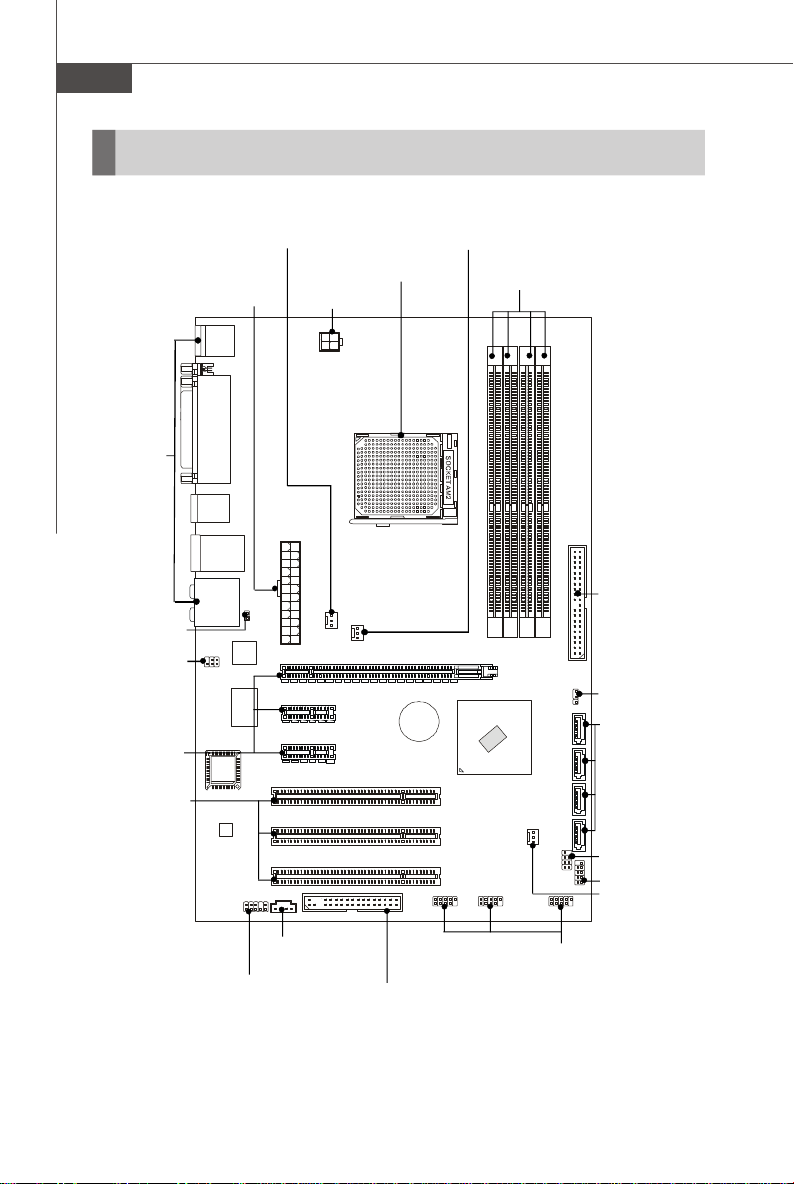
Page 14
MS-7260 Mainboard
BIOS
JUSB2
JUSB3
ALC883
PCI _EX3
PCI _EX2
JCD1
PCI _EX1
BATT+nvidia
nForce 550
JBAT1
JUSB1
NBFAN1
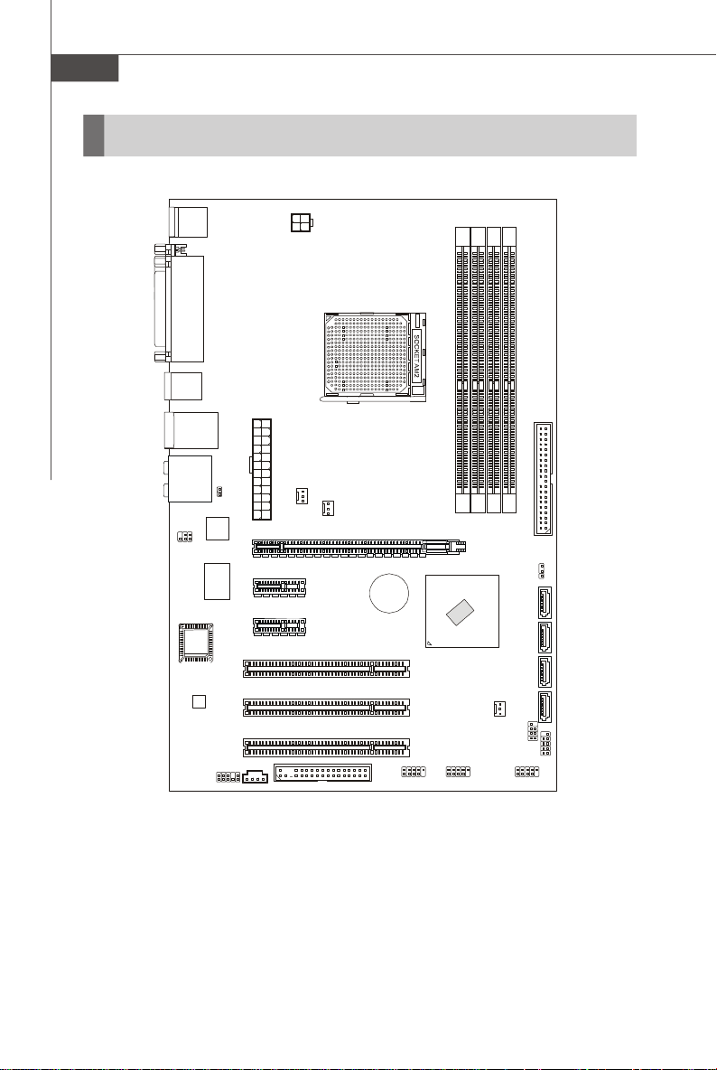
Mainboard Layout
Top : mouse
Bottom: keyboard
Top : Parallel Port
Bottom:
COM Port
USB ports
T: LAN jack
B: USB ports
T:
Line-In
M:
Line-Out
B:
Mic
T:SS-Out
M:CS
-Out
B:RS-Out
JCI1
LAN
JIR1
Chip
Winbond
I/O
JAUD1
JPW1
IDE1
SYSFAN1
ATX2
CPUFAN1
PCI 1
DIMM1
DIMM2
DIMM3
DIMM4
SATA3 SATA4
PCI 2
PCI 3
FDD1
JFP2
SATA1 SATA2
JFP1
K9N Neo Series
(MS-7260 v1.X) ATX Mainboard
1-4
Page 15
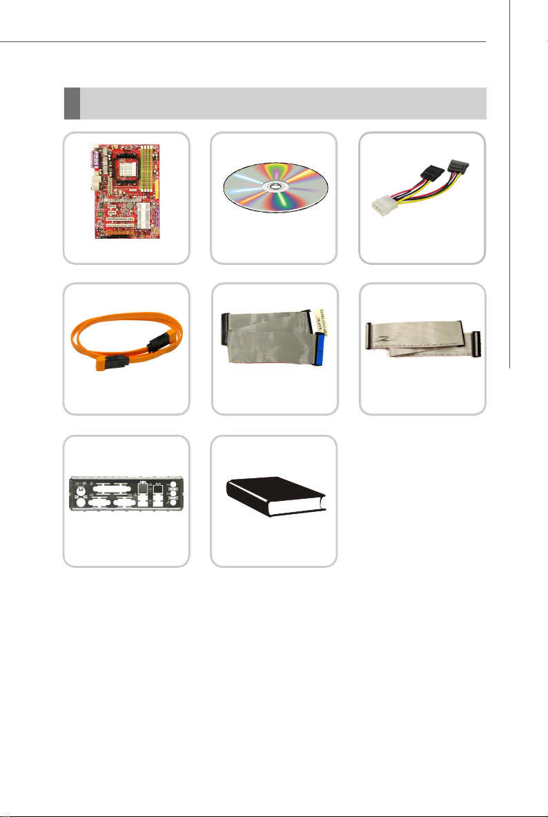
Packing Checklist
Getting Started
MSI motherboard
SATA Cable
Back IO Shield
* The pictures are for reference only and may vary from the packing contents of the
product you purchased.
MSI Driver/Utility CD
Standard Cable for
IDE Devices
User’ s Guide
Power Cable
Standard Cable for
Floppy Disk
1-5
Page 16

MS-7260 Mainboard
MSI Special Feature
Core Center
The Core Center is a new utility you can find in the CD-ROM disk. The utility is just like
your PC doctor that can detect, view and adjust the PC hardware and system status
during real time operation.
Cool’n’Quiet
This utility provides a CPU temperature detection function called Cool’n’Quiet .
Cool’n’Quiet is a special feature designed only for AMD® Athlon64 processor, and
with Cool’n’Quiet, the system will be capable of detecting the temperature of the
CPU according to the CPU’s working loading. When the CPU temperature climbs up to
a certain degree, the speed of the system cooling fan will be risen automatically. On
the other hand, the speed of the system cooling fan will slow down instantly when
the CPU temperature descends to its normal degree.
Here the current system status (including Vcore, 3.3V, +5V and 12V) and the current
PC hardware status (such as the CPU & system temperatures and all fans speeds)
are shown on the left and right sides for you to monitor.
When you click the red triangles in the left and right sides, two sub-menus will open
for users to overclock, overspec or to adjust the thresholds of system to send out the
warning messages.
1-6
Page 17
Getting Started
Left-side: Current system status
In the left sub-menu, you can configure the settings of FSB, Vcore, Memory Voltage
and AGP Voltage by clicking the radio button in front of each item and make it available
(the radio button will be lighted as yellow when selected), use the “ +” and “ -” buttons
to adjust, then click “OK” to apply the changes. Then you can click “Save” to save
the desired FSB you just configured.
Right-side: PC hardware status during real time operation
In the right sub-menu, here you can configure the PC hardware status such as CPU
& system temperatures and fan speeds. You may use the scroll bars to adjust each
item, then click “OK” to apply the changes. The values you set for the temperatures
are the maximum thresholds for the system warnings, and the values for fan speeds
are the minimum thresholds.
Center-side: Cool’n’Quiet / User mode
Here you may adjust the CPU fan speed. If you choose User mode, you may adjust
the CPU fan speed in 8 different modes, from High Speed to Low speed. If you
choose Cool’n’ Quiet, the system will automatically configure an optimal setting for
you.
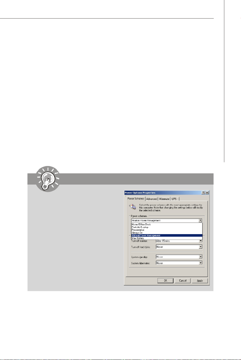
Important
To ensure that Cool’n’Quiet function
is activated and will be working
properly, it is required to double confirm that:
1.Run BIOS Setup, and select H/W
Monitor. Under H/W Monitor ,
find Cool’n’Quiet, and set this
item to [Enable].
2.Enter Windows, and select
[Start]->[Settings]->[Control
Pannel]->[Power Options]. Enter
Power Options Properties tag,
and select Minimal Power Man-
agement under Power schemes.
1-7
Page 18

Hardware Setup
Chapter 2
Hardware Setup
This chapter provides you with the information about
hardware setup procedures. While doing the installation,
be careful in holding the components and follow the
installation procedures. For some components, if you
install in the wrong orientation, the components will not
work properly.
Use a grounded wrist strap before handling computer
components. Static electricity may damage the
components.
2-1
Page 19
MS-7260 Mainboard
Quick Components Guide
Back Panel
I/O, p.2-10
JCI1, p.2-14
JIR1, p.2-15
PCIE Slots,
p.2-19
PCI Slots,
p.2-20
SYSFAN1, p.2-14
ATX2,
p.2-8
JPW1,
p.2-8
CPU, p.2-3
CPUFAN1, p.2-14
DDRII DIMMs, p.2-6
IDE1, p.2-12
JBAT1, p.2-16
SATA1~4,
p.2-13
2-2
JAUD1, p.2-15
JCD1, p.2-14
FDD1, p.2-12
JFP2, p.2-17
JFP1, p.2-17
NBFAN1, p.2-14
JUSB1~3, p.2-16
Page 20

Hardware Setup
CPU (Central Processing Unit)
The mainboard supports AMD® Athlon 64/ X2 & Sempron processors. The mainboard
uses a CPU socket called Socket AM2 (940-pin) for easy CPU installation. When you
are installing the CPU, make sure the CPU has a heat sink and a cooling fan
attached on the top to prevent overheating. If you do not have the heat sink and
cooling fan, contact your dealer to purchase and install them before turning on the
computer.
For the latest information about CPU, please visit http://www.msi.com.tw/program/
products/mainboard/mbd/pro_mbd_cpu_support.php
Important
1. Overheating will seriously damage the CPU and system. Always make
sure the cooling fan can work properly to protect the CPU from overheating.
2. Make sure that you apply an even layer of heat sink paste (or thermal tape)
between the CPU and the heatsink to enhance heat dissipation.
3. While replacing the CPU, always turn off the ATX power supply or unplug
the power supply’s power cord from the grounded outlet first to ensure the
safety of CPU.
2-3
Page 21
MS-7260 Mainboard
Gold arrow
Gold arrow
Gold arrow
Correct CPU placement
O
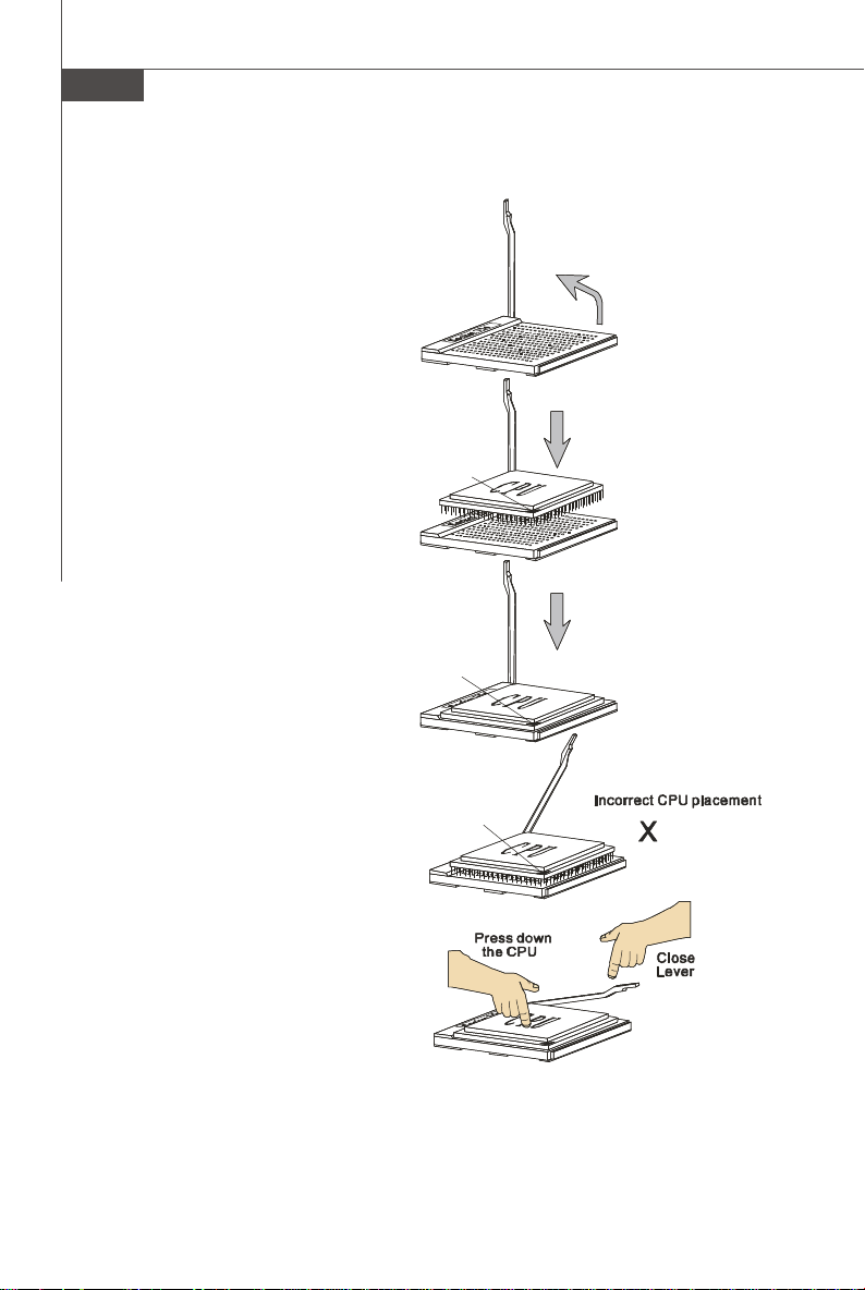
CPU Installation Procedures for Socket AM2
1.Please turn off the power and
unplug the power cord before
installing the CPU.
2.Pull the lever sideways away
from the socket. Make sure to
raise the lever up to a 90-degree angle.
3.Look for the gold arrow of the
CPU. The gold arrow should
point as shown in the picture.
The CPU can only fit in the correct orientation.
4.If the CPU is correctly installed,
the pins should be completely
embedded into the socket and
can not be seen. Please note
that any violation of the correct
installation procedures may
cause permanent damages to
your mainboard.
Sliding
Plate
Open Lever
90 degree
5. Press the CPU down firmly into
the socket and close the lever.
As the CPU is likely to move while
the lever is being closed, always close the lever with your
fingers pressing tightly on top of
the CPU to make sure the CPU is
properly and completely embedded into the socket.
2-4
Page 22
Hardware Setup
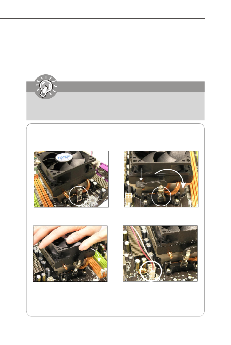
Installing AMD Socket AM2 CPU Cooler Set
When you are installing the CPU, make sure the CPU has a heat sink and a
cooling fan attached on the top to prevent overheating. If you do not have the
heat sink and cooling fan, contact your dealer to purchase and install them before
turning on the computer.
Important
Mainboard photos shown in this section are for demonstration of the cooler
installation for Socket AM2 CPUs only. The appearance of your mainboard
may vary depending on the model you purchase.
1.Position the cooling set onto the retention mechanism.
Hook one end of the clip to hook
first.
3.Fasten down the lever.
* While disconnecting the Safety Hook from the fixed bolt, it is necessary to
keep an eye on your fingers, because once the Safety Hook is disconnected
from the fixed bolt, the fixed lever will spring back instantly.
2. Then press down the other end of
the clip to fasten the cooling set on
the top of the retention mechanism.
Locate the Fix Lever and lift up it .
Fixed Lever
4.Attach the CPU Fan cable to the CPU
fan connector on the mainboard.
2-5
Page 23
MS-7260 Mainboard
1
2
3
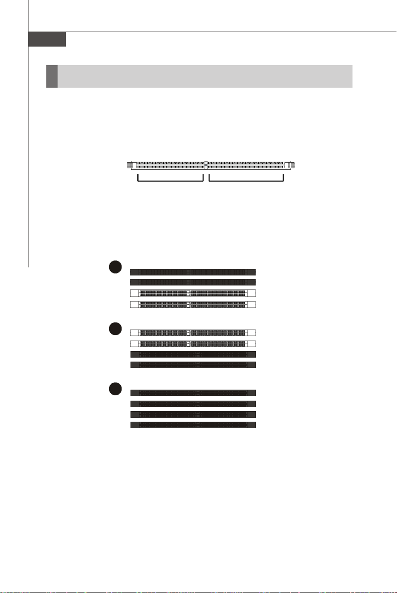
Memory
The mainboard provides four 240-pin non-ECC DDRII DIMMs and supports up to 4GB
system memory.
For more information on compatible components, please visit http://www.msi.com.tw/
program/products/mainboard/mbd/pro_mbd_trp_list.php
DDRII
240-pin, 1.8V
64x2=128 pin56x2=112 pin
Dual-Channel Memory Population Rules
DIMM1
DIMM2
DIMM3
DIMM4
DIMM1
DIMM2
DIMM3
DIMM4
DIMM1
DIMM2
DIMM3
DIMM4
2-6
Page 24
Hardware Setup
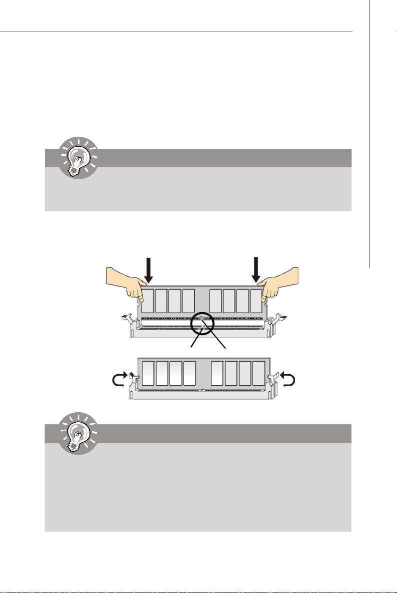
Installing DDRII Modules
1. The memory module has only one notch on the center and will only fit in the right
orientation.
2. Insert the DIMM memory module vertically into the DIMM slot. Then push it in until the
golden finger on the memory module is deeply inserted in the socket.
Important
You can barely see the golden finger if the module is properly inserted in the
socket.
3. The plastic clip at each side of the DIMM slot will automatically close.
Volt
Notch
Important
-DDRII modules are not interchangeable with DDR and the DDRII standard is
not backwards compatible. You should always install DDRII memory modules in the DDRII DIMMs and DDR memory modules in the DDR DIMMs.
-In dual-channel mode, make sure that you install memory modules of the
same type and density in differentchannel DDR DIMMs.
-To enable successful system boot-up, always insert the memory modules
into the DIMM1 first.
2-7
Page 25
MS-7260 Mainboard
Power Supply
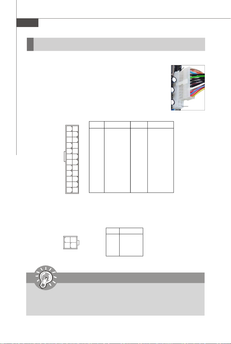
ATX 24-Pin Power Connector: ATX2
This connector allows you to connect an ATX 24-pin power supply.
To connect the ATX 24-pin power supply, make sure the plug of the
power supply is inserted in the proper orientation and the pins are
aligned. Then push down the power supply firmly into the connector.
You may use the 20-pin ATX power supply as you like. If you’d like
to use the 20-pin ATX power supply, please plug your power supply along with pin 1 & pin 13 (refer to the image at the right hand).
There is also a foolproof design on pin 11, 12, 23 & 24 to avoid
wrong installation.
13
ATX2
1
1224
PIN SIGNAL
1 +3.3V
2 +3.3V.
3 GND
4 +5V
5 GND
6 +5V
7 GND
8 PWR OK
9 5VSB
10 +12V
11 +12V
12 +3.3V
Pin Definition
PIN SIGNAL
13 +3.3V
14 -12V
15 GND
16 PS-ON#
17 GND
18 GND
19 GND
20 Res
21 +5V
22 +5V
23 +5V
24 GND
pin 13
pin 12
ATX 12V Power Connector: JPW1
This 12V power connector is used to provide power to the CPU.
JPW1
1
3
42
JPW1 Pin Definition
PIN SIGNAL
1 GND
2 GND
3 12V
4 12V
Important
1. Maker sure that all the connectors are connected to proper ATX power supplies to ensure stable operation of the mainboard.
2. Power supply of 350 watts (and above) is highly recommended for system
stability.
2-8
Page 26
Hardware Setup
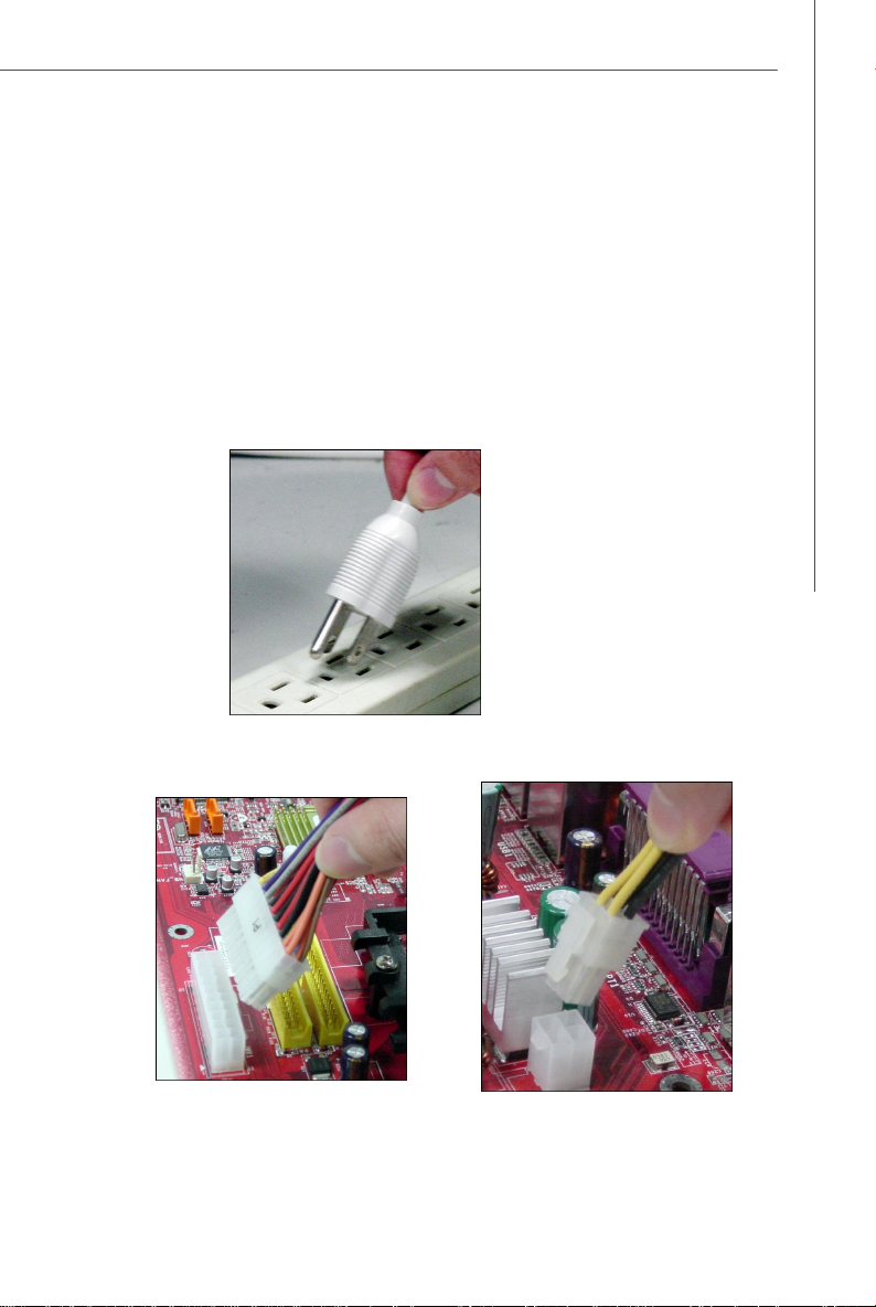
Important Notification about Power Issue
NForce chipset is very sensitive to ESD (Electrostatic Discharge), therefore this
issue mostly happens while the users intensively swap memory modules under S5
(power-off) states, and the power code is plugged while installing modules. Due to
several pins are very sensitive to ESD, so this kind of memory-replacement actions
might cause system chipset unable to boot. Please follow the following solution to
avoid this situation.
Unplug the AC power cable (shown in figure 1) or unplug the ATX2 & JPW1 power
connectors (shown in figure 2 & figure 3) before the 1st installation or during system
upgrade procedure.
Unplug the ATX2 power conn.
Figure 2:
Unplug the AC power cable
Figure 1:
Figure 3:
Unplug the JPW1 power conn.
2-9
Page 27
MS-7260 Mainboard
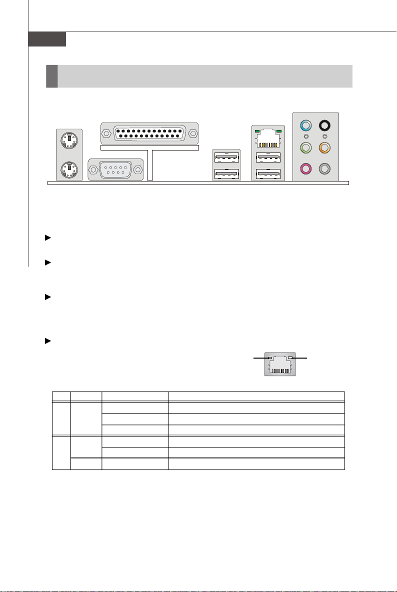
Back Panel
L-In
L-Out
Mic
RS-Out
CS-Out
SS-Out
Link Indicator
(Right LED)
Mouse
Keyboard
Parallel Port
Serial Port
LAN
USB Ports
LAN
Mouse/Keyboard Connector
The standard PS/2® mouse/keyboard DIN connector is for a PS/2® mouse/keyboard.
Parallel Port Connector
A parallel port is a standard printer port that supports Enhanced Parallel Port (EPP)
and Extended Capabilities Parallel Port (ECP) mode.
Serial Port Connector
The serial port is a 16550A high speed communications port that sends/ receives 16
bytes FIFOs. You can attach a serial mouse or other serial devices directly to the
connector.
LAN (RJ-45) Jack
The standard RJ-45 jack is for connection
to single Local Area Network (LAN). You
can connect a network cable to it.
Activity Indicator
(Left LED)
LED Color LED State condition
Off LAN link is not established.
Left Yellow On (steady state) LAN link is established.
On (brighter & pulsing)The computer is communicating with another computer on the LAN.
Green Off 10 Mbit/sec data rate is selected.
Right On 100 Mbit/sec data rate is selected.
Orange On 1000 Mbit/sec data rate is selected.
2-10
Page 28

Hardware Setup
USB Connectors
The OHCI (Open Host Controller Interface) Universal Serial Bus root is for attaching
USB devices such as keyboard, mouse, or other USB-compatible devices.
Audio Port Connectors
These audio connectors are used for audio devices. You can differentiate the color
of the audio jacks for different audio sound effects.
Green audio jack - Line Out, is a connector for speakers or headphones.
Blue audio jack - Line In / Side-Surround Out in 7.1 channel mode, is used
for external CD player, tapeplayer or other audio
devices.
Pink audio jack - Mic In, is a connector for microphones.
Orange audio jack - Center/ Subwoofer Out in 5.1/ 7.1 channel mode.
Black audio jack - Rear-Surround Out in 5.1/ 7.1 channel mode.
Gray audio jack - Side-Surround Out in 7.1 channel mode.
2-11
Page 29
MS-7260 Mainboard
Connectors
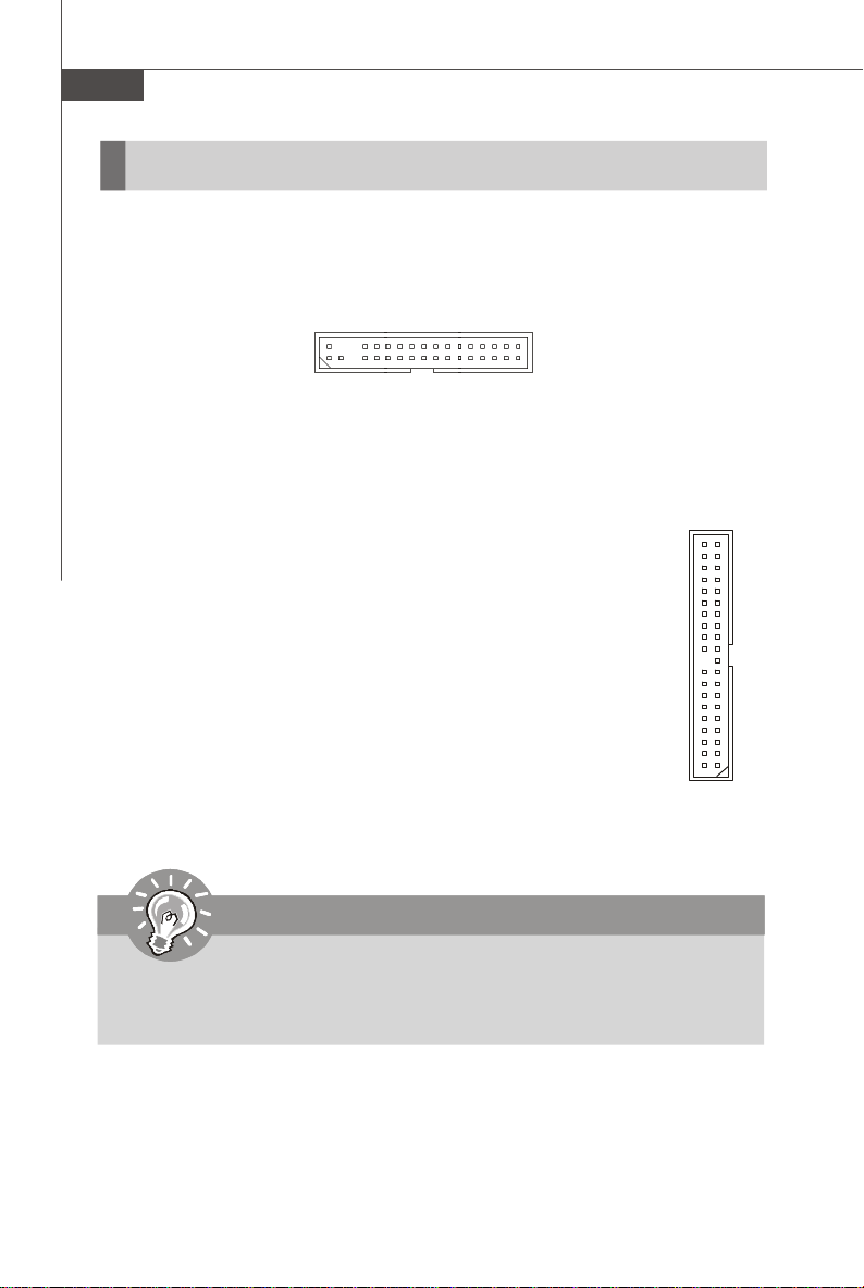
Floppy Disk Drive Connector: FDD1
This standard FDD connector supports 360K, 720K, 1.2M, 1.44M and 2.88M floppy
disk types.
FDD1
ATA133 Hard Disk Connectors: IDE1
The mainboard has a 32-bit Enhanced PCI IDE and Ultra DMA 66/100/133
controller that provides PIO mode 0~4, Bus Master, and Ultra DMA 66/
100/133 function. You can connect hard disk drives, CD-ROM and other
IDE devices.
The Ultra ATA133 interface boosts data transfer rates between the
computer and the hard drive up to 133 megabytes (MB) per second. The
new interface is one-third faster than earlier record-breaking Ultra ATA/
100 technology and is backwards compatible with the existing Ultra ATA
interface.
IDE1 (Primary IDE Connector)
IDE1 can connect a Master and a Slave drive. You must configure the
second hard drive to Slave mode by setting the jumper accordingly.
IDE1
Important
If you install two hard disks on cable, you must configure the second drive to
Slave mode by setting its jumper. Refer to the hard disk documentation
supplied by hard disk vendors for jumper setting instructions.
2-12
Page 30
Hardware Setup
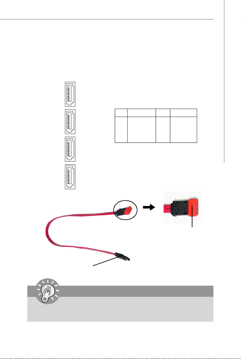
Serial ATA II Connectors: SATA1~SATA4
SATA1~SATA4 are high-speed SATAII interface ports. Each supports data rates of
300 MB/s and is fully compliant with Serial ATA specifications. Each Serial ATA connector can connect to 1 hard disk device.
1
SATA4
SATA3
SATA2
SATA1
7
PIN SIGNAL PIN SIGNAL
1 GND 2 TXP
3 TXN 4 GND
5 RXN 6 RXP
7 GND
Pin Definition
Serial ATA cable
Take out the dust cover
and connect to the hard
disk devices
Connect to SATA connector
Important
Please do not fold the Serial ATA cable into 90-degree angle. Otherwise,
data loss may occur during transmission.
2-13
Page 31

MS-7260 Mainboard
Fan Power Connectors: CPUFAN1, SYSFAN1 & NBFAN1
The fan power connectors support system cooling fan with +12V. When connecting
the wire to the connectors, always take note that the red wire is the positive and
should be connected to the +12V, the black wire is Ground and should be connected
to GND. If the mainboard has a System Hardware Monitor chipset on-board, you must
use a specially designed fan with speed sensor to take advantage of the CPU fan
control.
GND
+12V
SENSOR
CPUFAN1 SYSFAN1
GND
+12V
SENSOR
GND
+12V
NC
NBFAN1
Important
1.Please refer to the recommended CPU fans at AMD® official website or
consult the vendors for proper CPU cooling fan.
2.Always consult the vendors for proper CPU cooling fan.
Chassis Intrusion Switch Connector: JCI1
This connector connects to a 2-pin chassis switch. If the chassis is opened, the
switch will be short. The system will record this status and show a warning message on the screen. To clear the warning, you must enter the BIOS utility and clear the
record.
GND
2
CINTRU
1
JCI1
CD-In Connector: JCD1
This connector is provided for CD-ROM audio.
2-14
JCD1
R
GND
L
Page 32

Hardware Setup
Front Panel Audio Connector: JAUD1
The JAUD1 front panel audio connector allows you to connect the front panel audio
and is compliant with Intel® Front Panel I/O Connectivity Design Guide.
2
1
10
9
JAUD1
JAUD1 Pin Definition
PIN SIGNAL DESCRIPTION
1 PORT 1L Analog Port 1 - Left channel
2 GND Ground
3 PORT 1R Analog Port 1 - Right channel
4 PRESENCE# Active low signal - signals BIOS that a High Definition Audio
5 PORT 2R Analog Port 2 - Right channel
6 SENSE1_RETIRN Jack detection return from front panel JACK1
7 SENSE_SEND Jack detection sense line from the High Definition Audio CODEC
8 KEY Connector Key
9 PORT 2L Analog Port 2 - Left channel
10 SENSE2_RETIRN Jack detection return from front panel JACK2
dongle is connected to the analog header. PRESENCE# = 0
when a High Definition Audio dongle is connected.
jack detection resistor network
IrDA Infrared Module Header: JIR1
The connector allows you to connect to IrDA Infrared module. You must configure the
setting through the BIOS setup to use the IR function. JIR1 is compliant with Intel
Front Panel I/O Connectivity Design Guide.
Pin Definition
JIR1
2
6
1
5
Pin Signal
1 NC
2 NC
3 VCC5
4 GND
5 IRTX
6 IRRX
®
2-15
Page 33

MS-7260 Mainboard
Front USB Connectors: JUSB1, JUSB2 & JUSB3
The mainboard provides USB 2.0 pinheaders (optional USB 2.0 bracket available) that
are compliant with Intel® I/O Connectivity Design Guide. USB 2.0 technology increases
data transfer rate up to a maximum throughput of 480Mbps, which is 40 times faster
than USB 1.1, and is ideal for connecting high-speed USB interface peripherals such
as USB HDD, digital cameras , MP3 players , printers, modems and the like.
Pin Definition
JUSB1/2/3
2
1
Connected to USB connector
10
9
PIN SIGNAL PIN SIGNAL
1 VCC 2 VCC
3 USB0- 4 USB15 USB0+ 6 USB1+
7 GND 8 GND
9 Key (no pin) 10 USBOC
USB 2.0 Bracket
(Optional)
Important
Note that the pins of VCC and GND must be connected correctly to avoid
possible damage.
2-16
Page 34

Hardware Setup
Front Panel Connectors: JFP1/JFP2
The mainboard provides two front panel connectors for electrical connection to the
front panel switches and LEDs. The JFP1 is compliant with Intel® Front Panel I/O
Connectivity Design Guide.
JFP1
910
-
Power
Switch++
Power
LED
JFP1 Pin Definition
PIN SIGNAL DESCRIPTION
1 HD_LED + Hard disk LED pull-up
2 FP PWR/SLP MSG LED pull-up
3 HD_LED - Hard disk active LED
4 FP PWR/SLP MSG LED pull-up
5 RST_SW - Reset Switch low reference pull-down to GND
6 PWR_SW + Power Switch high reference pull-up
7 RST_SW + Reset Switch high reference pull-up
8 PWR_SW - Power Switch low reference pull-down to GND
9 RSVD_DNU Reserved. Do not use.
+
Reset
-
Switch
-
HDD
LED
2
1
JFP2
8
7
+
Speaker
JFP2 Pin Definition
PIN SIGNAL DESCRIPTION
1 GND Ground
2 SPK- Speaker3 SLED Suspend LED
4 BUZ+ Buzzer+
5 PLED Power LED
6 BUZ- Buzzer7 NC No connection
8 SPK+ Speaker+
-
Power
+
-
LED
12
2-17
Page 35

MS-7260 Mainboard
Jumper
The motherboard provides the following jumper for you to set the computer’s function.
This section will explain how to change your motherboard’s function through the use
of jumper.
Clear CMOS Jumper: JBAT1
There is a CMOS RAM onboard that has a power supply from external battery to keep
the data of system configuration. With the CMOS RAM, the system can automatically
boot OS every time it is turned on. If you want to clear the system configuration, set
the JCMOS1 (Clear CMOS Jumper ) to clear data.
1
JBAT1
3
1
Keep Data
3
1
Clear Data
Important
You can clear CMOS by shorting 2-3 pin while the system is off. Then return
to 1-2 pin position. Avoid clearing the CMOS while the system is on; it will
damage the mainboard.
2-18
Page 36

Hardware Setup
Slots
PCI (Peripheral Component Interconnect) Express Slots
PCI Express architecture provides a high performance I/O infrastructure for Desktop
Platforms with transfer rates starting at 2.5 Giga transfers per second over a PCI
Express x1 lane for Gigabit Ethernet, TV Tuners, 1394 controllers, and general purpose I/O. Also, desktop platforms with PCI Express Architecture will be designed to
deliver highest performance in video, graphics, multimedia and other sophisticated
applications. Moreover, PCI Express architecture provides a high performance graphics
infrastructure for Desktop Platforms doubling the capability of existing AGP 8x designs with transfer rates of 4.0 GB/s over a PCI Express x16 lane for graphics
controllers, while PCI Express x1 supports transfer rate of 250 MB/s.
PCI Express x16 Slot
PCI Express x1 Slot
Important
1. When adding or removing expansion cards, make sure that you unplug the
power supply first. Meanwhile, read the documentation for the expansion card
to configure any necessary hardware or software settings for the expansion
card, such as jumpers, switches or BIOS configuration.
2-19
Page 37

MS-7260 Mainboard
PCI (Peripheral Component Interconnect) Slots
The PCI slots support LAN cards, SCSI cards, USB cards, and other add-on cards
that comply with PCI specifications. At 32 bits and 33 MHz, it yields a throughput rate
of 133 MBps.
32-bit PCI Slot
PCI Interrupt Request Routing
The IRQ, acronym of interrupt request line and pronounced I-R-Q, are hardware lines
over which devices can send interrupt signals to the microprocessor. The PCI IRQ
pins are typically connected to the PCI bus pins as follows:
Order 1 Order 2 Order 3 Order 4
PCI Slot 1 INT E# INT F# INT G# INT H#
PCI Slot 2 INT F# INT G# INT H# INT E#
PCI Slot 3 INT G# INT H# INT E# INT F#
2-20
Page 38

Chapter 3
BIOS Setup
This chapter provides information on the BIOS Setup
program and allows you to configure the system for
optimum use.
You may need to run the Setup program when:
² An error message appears on the screen during the
system booting up, and requests you to run SETUP.
² You want to change the default settings for cus-
tomized features.
BIOS Setup
3-1
Page 39

MS-7260 Mainboard
Entering Setup
Power on the computer and the system will start POST (Power On Self Test) process.
When the message below appears on the screen, press <DEL> key to enter Setup.
Press DEL to enter SETUP
If the message disappears before you respond and you still wish to enter Setup,
restart the system by turning it OFF and On or pressing the RESET button. You may
also restart the system by simultaneously pressing <Ctrl>, <Alt>, and <Delete> keys.
Important
1.The items under each BIOS category described in this chapter are under
continuous update for better system performance. Therefore, the description may be slightly different from the latest BIOS and should be held for
reference only.
2.Upon boot-up, the 1st line appearing after the memory count is the BIOS
version. It is usually in the format:
3-2
A7260NMS V1.0 041506 where:
1st digit refers to BIOS maker as A = AMI, W = AWARD, and P =
PHOENIX.
2nd - 5th digit refers to the model number.
6th digit refers to the chipset as I = Intel, N = nVidia, and V = VIA.
7th - 8th digit refers to the customer as MS = all standard customers.
V1.0 refers to the BIOS version.
041506 refers to the date this BIOS was released.
Page 40

BIOS Setup
Control Keys
<↑> Move to the previous item
<↓> Move to the next item
<←> Move to the item in the left hand
< →> Move to the item in the right hand
<Enter> Select the item
<Esc> Jumps to the Exit menu or returns to the main menu from a
submenu
<+/PU> Increase the numeric value or make changes
<-/PD> Decrease the numeric value or make changes
<F6> Load Optimized Defaults
<F7> Load Fail-Safe Defaults
<F10> Save all the CMOS changes and exit
Getting Help
After entering the Setup menu, the first menu you will see is the Main Menu.
Main Menu
The main menu lists the setup functions you can make changes to. You can use the
arrow keys ( ↑↓ ) to select the item. The on-line description of the highlighted setup
function is displayed at the bottom of the screen.
Sub-Menu
If you find a right pointer symbol (as shown in the
right view) appears to the left of certain fields that
means a sub-menu can be launched from this field. A
sub-menu contains additional options for a field
parameter. You can use arrow keys ( ↑↓ ) to highlight the field and press <Enter> to call up the sub-menu. Then you can use the control
keys to enter values and move from field to field within a sub-menu. If you want to
return to the main menu, just press the <Esc >.
General Help <F1>
The BIOS setup program provides a General Help screen. You can call up this screen
from any menu by simply pressing <F1>. The Help screen lists the appropriate keys
to use and the possible selections for the highlighted item. Press <Esc> to exit the
Help screen.
3-3
Page 41

MS-7260 Mainboard
The Main Menu
Standard CMOS Features
Use this menu for basic system configurations, such as time, date etc.
Advanced BIOS Features
Use this menu to setup the items of AMI® special enhanced features.
Advanced Chipset Features
Use this menu to change the values in the chipset registers and optimize your system’s
performance.
Integrated Peripherals
Use this menu to specify your settings for integrated peripherals.
Power Management Setup
Use this menu to specify your settings for power management.
PNP/PCI Configurations
This entry appears if your system supports PnP/PCI.
H/W Monitor
This entry shows your PC health status.
Cell Menu
Use this menu to specify your settings for frequency/voltage control and overclocking.
3-4
Page 42

BIOS Setup
Load Optimized Defaults
Use this menu to load the default values set by the mainboard manufacturer specifically for optimal performance of the mainboard.
BIOS Setting Password
Use this menu to set the password for BIOS.
Save & Exit Setup
Save changes to CMOS and exit setup.
Exit Without Saving
Abandon all changes and exit setup.
3-5
Page 43

MS-7260 Mainboard
Standard CMOS Features
The items in Standard CMOS Features Menu includes some basic setup items. Use
the arrow keys to highlight the item and then use the <PgUp> or <PgDn> keys to select
the value you want in each item.
Date (MM:DD:YY)
This allows you to set the system to the date that you want (usually the current date).
The format is <day><month> <date> <year>.
day Day of the week, from Sun to Sat, determined by
month The month from Jan. through Dec.
date The date from 1 to 31 can be keyed by numeric function keys.
year The year can be adjusted by users.
BIOS. Read-only.
Time (HH:MM:SS)
This allows you to set the system time that you want (usually the current time). The
time format is <hour> <minute> <second>.
IDE Primary Master/ Slave, Serial-ATA 0/1 Primary/ Secondary Channel
Press <Enter> to enter the sub-menu, and the following screen appears.
3-6
Page 44

BIOS Setup
Device/ Vender/ Size/ LBA Mode/ Block Mode/ PIO Mode/ Async DMA/
Ultra DMA/ S.M.A.R.T.
It will showing the device information that you connected to the IDE/SATA
connector.
LBA/Large Mode
This allows you to enable or disable the LBA Mode. Setting to Auto enables LBA
mode if the device supports it and the devices is not already formatted with LBA
mode disabled.
DMA Mode
Select DMA Mode.
Hard Disk S.M.A.R.T.
This allows you to activate the S.M.A.R.T. (Self-Monitoring Analysis & Reporting
Technology) capability for the hard disks. S.M.A.R.T is a utility that monitors your
disk status to predict hard disk failure. This gives you an opportunity to move
data from a hard disk that is going to fail to a safe place before the hard disk
becomes offline.
Important
IDE Primary Master/ Slave, Serial-ATA 0/ 1 Primary/ Secondary
Channel are appearing when you connect the HD devices to the IDE/
SATA connector on the mainboard.
Floppy Drive A
This item allows you to set the type of floppy drives installed.
3-7
Page 45

MS-7260 Mainboard
Halt On
The setting determines whether the system will stop if an error is detected at boot.
Available options are:
[No Errors] The system doesn’t stop for any detected error.
[All, But Keyboard] The system doesn’t stop for a keyboard error.
System Information
Press <Enter> to enter the sub-menu, and the following screen appears.
Usage Memory/ BIOS Version
These items show the CPU information, BIOS version and memory status of your
system (read only).
3-8
Page 46

BIOS Setup
Advanced BIOS Features
Quick Booting
Setting the item to [Enabled] allows the system to boot within 5 seconds since it will
skip some check items.
Full Screen LOGO Display
This item enables you to show the company logo on the bootup screen. Settings are:
[Enabled] Shows a still image (logo) on the full screen at boot.
[Disabled] Shows the POST messages at boot.
Boot Up NumLock LED
This setting is to set the Num Lock status when the system is powered on. Setting to
[On] will turn on the Num Lock key when the system is powered on. Setting to [Off]
will allow users to use the arrow keys on the numeric keypad.
Boot To OS/2
This allows you to run the OS/2® operating system with DRAM larger than 64MB.
When you choose [No], you cannot run the OS/2® operating system with DRAM
larger than 64MB. But it is possible if you choose [Yes].
IOAPIC Function
This field is used to enable or disable the APIC (Advanced Programmable Interrupt
Controller). Due to compliance with PC2001 design guide, the system is able to run in
APIC mode. Enabling APIC mode will expand available IRQ resources for the system.
3-9
Page 47

MS-7260 Mainboard
MPS Table Version
This field allows you to select which MPS (Multi-Processor Specification) version to
be used for the operating system. You need to select the MPS version supported by
your operating system. To find out which version to use, consult the vendor of your
operating system.
Boot Sequence
Press <Enter> to enter the sub-menu and the following screen appears:
1st Boot Device
The items allow you to set the sequence of boot devices where BIOS attempts
to load the disk operating system.
Hard Disk Drives
This feature allows you to specify the hard disk boot priority.
Removable Drives
This feature allows you to specify the removable device boot priority.
CD/DVD Drives
This feature allows you to specify the CD/DVD device boot priority.
Other Drives
This feature allows you to specify the other device boot priority.
3-10
Page 48

BIOS Setup
Advanced Chipset Features
Memory Configuration
Press <Enter> to enter the sub-menu and the following screen appears:
Memclock Mode
Select the DRAM frequency programming method. If set to “Auto”, the DRAM
speed will be based on SPDs. If set to “ Limit”, the DRAM speed will not exceed
the specified value. If set to “Manual”, the DRAM speed specified will be programmed regardless of SPD.
MCT Timing Mode
This field has the capacity to automatically detect all of the DRAM timing. If you
set this field to [Manual], the following fields will be selectable.
3-11
Page 49

MS-7260 Mainboard
Memory Hole
In order to improve performance, certain space in memory can be reserved for
ISA peripherals. This memory must be mapped into the memory space below
16MB. When this area is reserved, it cannot be cached. Settings: Disabled,
15MB-16MB.
Hyper Transport Configuration
Press <Enter> to enter the sub-menu and the following screen appears:
SB to CPU Freq. Auto
[Enabled] Auto Detect HT frequency.
[Disabled] Manual to setting HT frequency.
SB to CPU Frequency
When the SB to CPU Freq. Auto set to Disabled, the item will appear. This item
allows you to select the frequency from South Bridge to CPU.
SB to CPU LinkWidth
This item allows you to select the HT width from SB to CPU.
3-12
Page 50

BIOS Setup
Integrated Peripherals
USB / 2.0 Controller
This setting allows you to enable/disable the onboard USB 1.1/ 2.0 controller.
USB Device Legacy Support
Select [Enabled] if you need to use a USB-interfaced device in the operating system.
Onboard LAN Controller
These items are used to enable/disable the onboard LAN controller.
Onboard Audio Controller
This setting is used to enable/disable the onboard audio controller.
On-Chip ATA Devices
Press <Enter> to enter the sub-menu and the following screen appears:
PCI IDE BusMaster
This item allows you to enable/ disable BIOS to used PCI busmastering for
reading/ writing to IDE drives.
3-13
Page 51

MS-7260 Mainboard
On-Chip IDE Controller
This item allows you to enable/ disable IDE Controller.
Serial-ATA Devices
These items allow users to enable or disable the SATA controller.
I/O Devices
Press <Enter> to enter the sub-menu and the following screen appears:
Onboard Floppy Controller
Select [Enabled] if your system has a floppy disk controller (FDD) installed on the
system board and you wish to use it. If you install add-on FDC or the system has
no floppy drive, select [Disabled] in this field.
COM Port 1/2
Select an address and corresponding interrupt for the first serial port.
COM Port 2 Mode
This setting allows you to specify the operation mode for serial port 2. Settings
are:
[IrDA] IrDA-compliant Serial Infrared Port
[ASKIR] Amplitude Shift Keyed Infrared Port
Parallel Port
There is a built-in parallel port on the on-board Super I/O chipset that provides
Standard, ECP, and EPP features. It has the following options:
Parallel Port Mode
[Disabled]
[3BC] Line Printer port 0
[278] Line Printer port 2
[378] Line Printer port 1
[SPP] Standard Parallel Port
[EPP] Enhanced Parallel Port
[ECP] Extended Capability Port
[ECP + EPP] Extended Capability Port + Enhanced Parallel Port
3-14
Page 52

BIOS Setup
To operate the onboard parallel port as Standard Parallel Port only, choose [SPP].
To operate the onboard parallel port in the EPP mode simultaneously, choose
[EPP]. By choosing [ECP], the onboard parallel port will operate in ECP mode only.
Choosing [ECP + EPP] will allow the onboard parallel port to support both the ECP
and EPP modes simultaneously.
Parallel Port IRQ
This item allows you to set parallel port IRQ.
nVidia RAID Setup
Press <Enter> to enter the sub-menu and the following screen appears:
nVidia RAID Function
This item is used to enable/disable the nVidia RAID function.
SATA 0/ 1 Primary/ Secondary Channel
These itemsallow users to enable or disable the RAID function for each SATA
hard disk drive.
3-15
Page 53

MS-7260 Mainboard
Power Management Setup
Important
S3-related functions described in this section are available only when your
BIOS supports S3 sleep mode.
ACPI Function
This item is to activate the ACPI (Advanced Configuration and Power Management
Interface) Function. If your operating system is ACPI-aware, such as Windows 98SE/
2000/ME, select [Enabled].
ACPI Standby State
This item specifies the power saving modes for ACPI function. If your operating
system supports ACPI, such as Windows 98SE/ ME/ 2000 , you can choose to enter
the Standby mode in S1(POS) or S3(STR) fashion through the setting of this field.
Settings are:
[S1/POS] The S1 sleep mode is a low power state. In this state, no
[S3/STR] The S3 sleep mode is a lower power state where the in
[Auto]
system context is lost (CPU or chipset) and hardware maintains all system context.
formation of system configuration and open applications/files
is saved to main memory that remains powered while most
other hardware components turn off to save energy. The
information stored in memory will be used to restore the system when a “wake up ” event occurs.
3-16
Page 54

BIOS Setup
Power Button Function
This feature sets the function of the power button. Settings are:
[On/ Off] The power button functions as normal power off button.
[Suspend] When you press the power button, the computer enters the
Restore On AC Power Loss
This item specifies whether your system will reboot after a power failure or interrupt
occurs. Settings are:
[Off] Always leaves the computer in the power off state.
[On] Always leaves the computer in the power on state.
[Last State] Restores the system to the status before power failure
Wakeup Event Setup
Press <Enter> and the following sub-menu appears.
suspend/sleep mode, but if the button is pressed for more
than four seconds, the computer is turned off.
or interrupt occurred.
Resume by PS/2 Keyboard
This controls how the PS/2 keyboard is able to power on the system. If you
choose Specific Key, the power button on the case will not function anymore
and you must type the password to power on the system.
Resume by PS/2 Mouse
This setting determines whether the system will be awakened from what power
saving modes when input signal of the PS/2 mouse is detected.
Resume by MAC LAN
An input signal on modem awakens the system from a soft off state.
Resume by PCI Device (PME#)
When set to [Enabled], the feature allows your system to be awakened from the
power saving modes through any event on PME (Power Management Event).
Resume by PCIE Device
When set to [Enabled], the feature allows your system to be awakened from the
power saving modes through any event on PCIE device.
3-17
Page 55

MS-7260 Mainboard
Resume by RTC Alarm
The field is used to enable or disable the feature of booting up the system on a
scheduled time/date.
3-18
Page 56

BIOS Setup
PNP/PCI Configurations
This section describes configuring the PCI bus system and PnP (Plug & Play) feature.
PCI, or Peripheral Component Interconnect, is a system which allows I/O devices to
operate at speeds nearing the speed the CPU itself uses when communicating with
its special components. This section covers some very technical items and it is
strongly recommended that only experienced users should make any changes to the
default settings.
Primary Graphics Adapter
This setting specifies which graphics card is your primary graphics adapter. Settings
are:
[PCIE] The system initializes the PCI Express graphics card that installed in
PCIE x 16 slot first.
[PCI] The system initializes the PCI graphics card that installed in PCI slot
first.
PCI Latency Timer
This item controls how long each PCI device can hold the bus before another takes
over. When set to higher values, every PCI device can conduct transactions for a
longer time and thus improve the effective PCI bandwidth. For better PCI performance,
you should set the item to higher values.
PCI Slot 1/2/3 IRQ
These items specify the IRQ line for each PCI slot.
3-19
Page 57

MS-7260 Mainboard
IRQ Resource Setup
Press <Enter> to enter the sub-menu and the following screen appears.
IRQ 3/4/5/7/9/10/11/14/15
These items specify the bus where the specified IRQ line is used.
The settings determine if AMIBIOS should remove an IRQ from the pool of available IRQs passed to devices that are configurable by the system BIOS. The
available IRQ pool is determined by reading the ESCD NVRAM. If more IRQs must
be removed from the IRQ pool, the end user can use these settings to reserve
the IRQ by assigning an [Reserved] setting to it. Onboard I/O is configured by
AMIBIOS. All IRQs used by onboard I/O are configured as [Available]. If all IRQs
are set to [Reserved], and IRQ 14/15 are allocated to the onboard PCI IDE, IRQ 9
will still be available for PCI and PnP devices.
Important
IRQ (Interrupt Request) lines are system resources allocated to I/O devices.
When an I/O device needs to gain attention of the operating system, it signals this by causing an IRQ to occur. After receiving the signal, when the
operating system is ready, the system will interrupt itself and perform the
service required by the I/O device.
DMA Resource Setup
Press <Enter> to enter the sub-menu and the following screen appears.
DMA Channel 0/1/3/5/6/7
The settings determine if AMIBIOS should remove a DMA (Direct Memory Access)
from the available DMAs passed to devices that are configurable by the system
BIOS. The available DMA pool is determined by reading the ESCD NVRAM. If more
DMAs must be removed from the pool, the end user can reserve the DMA.
3-20
Page 58

BIOS Setup
H/W Monitor
CPU Spread Spectrum
This setting is used to enable or disable the CPU Spread Spectrum feature. When
overclocking the CPU, always set it to [Disabled].
PCIE Spread Spectrum
This setting is used to enable or disable the PCIE Spread Spectrum feature.
SATA Spread Spectrum
This setting is used to enable or disable the SATA Spread Spectrum feature.
Cool’n’Quiet
This feature is especially desiged for AMD processor, which provides a CPU temperature detecting function to prevent your CPU’s from overheading due to the heavy
working loading.
Important
For the purpose of ensuring the stability of Cool'n'Quiet function, it is always
recommended to have the memories plugged in DIMM1.
3-21
Page 59

MS-7260 Mainboard
Chassis Intrusion
The field enables or disables the feature of recording the chassis intrusion status
and issuing a warning message if the chassis is once opened. To clear the warning
message, set the field to [Reset]. The setting of the field will automatically return to
[Enabled] later.
CPUFAN1 Mode Setting
This field allows you to set the CPU fan mode. Settings are: [Step Smart Fan], [Thermal
Cruise], [Disabled].
CPU Step Smart Fan Low/ High Temp
When the CPUFAN Mode Setting set to the “ Step Smart Fan”, this item will
apear. The mainboard provides another Smart Fan system which can control the
fan speed automatically depending on the current temperature to keep it within a
specific step. In these items you can set the low and high tempertures, and the
values between are the range of the steps.
CPUFAN1 Tolerance Value
When the CPUFAN Mode Setting set to the “Step Smart Fan”, this item will
apear. The Fan tolerance value will decide the intervals of the steps from low
temperature to high temperature. The fan speed will increase at higher steps
and decrease at lower steps according to the steps.
Current Smart Fan Step
This item shows how many steps between the low and high temperatures.
Read only.
Each Step Increase Fan Output
This item shows the percentage for the CPU fan speed to increase or decrease
between two steps. Read only.
CPU Fan TargetTemp Value
When the CPUFAN Mode Setting set to the “Thermal Cruise” this item will
appear. The mainboard provides the Smart Fan system which can control the
fan speed automatically depending on the current temperature to keep it with in
a specific range.
CPU Fan Tolerance Value
When the CPUFAN Mode Setting set to the “ Thermal Cruise” this item will
appear. You can select a fan tolerance value here for the specific range for the
“CPU Fan TargetTemp. Value” item. If the current temperature of the fan reaches
to the maximum threshold (the temperatures set in the “ CPU Fan TargetTemp.
Value” plus the tolerance values you set here), the fan will speed up for cooling
down. On the contrary, if the current temperature reaches to the minimum
threshold (the set temperatures minus the tolerance value), the fan will slow
down to keep the temperature stable.
3-22
Page 60

BIOS Setup
PC Health Status
Press <Enter> to enter the sub-menu and the following screen appears.
System/ CPU Temperature, CPUFAN/System FAN Speed, CPU Vcore,
+12.0V, +3.3V, +5.0V, 3VSB
These items display the current status of all of the monitored hardware devices/
components such as CPU voltage, temperatures and all fans’ speeds.
3-23
Page 61

MS-7260 Mainboard
Cell Menu
Important
Change these settings only if you are familiar with the chipset.
Current CPU Clock/ Memory Speed
These items show the current clocks of CPU and Memory speed. Read-only.
Adjust CPU FSB Frequency
This item allows you to select the CPU Front Side Bus clock frequency (in MHz).
CPU Dynamic OverClocking
Dynamic Overclocking Technology is the automatic overclocking function, included in
the MSITM’s newly developed CoreCell
balance of CPU while running programs, and to adjust the best CPU frequency
automatically. When the motherboard detects CPU is running programs, it will speed
up CPU automatically to make the program run smoothly and faster. When the CPU is
temporarily suspending or staying in the low load balance, it will restore the default
settings instead. Usually the Dynamic Overclocking Technology will be powered only
when users' PC need to run huge amount of data like 3D games or the video process,
and the CPU frequency need to be boosted up to enhance the overall performance.
Settings are:
TM
Technology. It is designed to detect the load
3-24
Page 62

BIOS Setup
[Disabled] Disable Dynamic Overclocking.
[Private] 1st level of overclocking, increasing the frequency by 1%.
[Sergeant] 2nd level of overclocking, increasing the frequency by 3%.
[Captain] 3rd level of overclocking, increasing the frequency by 5%.
[Colonel] 4th level of overclocking, increasing the frequency by 7%.
[General] 5th level of overclocking, increasing the frequency by 10%.
[Commander] 6th level of overclocking, increasing the frequency by 15%.
Important
Even though the Dynamic Overclocking Technology is more stable than
manual overclocking, basically, it is still risky. We suggest user to make
sure that your CPU can afford to overclocking regularly first. If you find the
PC appears to be unstable or reboot incidentally, it's better to disable the
Dynamic Overclocking or to lower the level of overclocking options. By the
way, if you need to conduct overclocking manually, you also need to disable
the Dynamic OverClocking first.
Adjust DDR Voltage
Adjusting the DDR voltage can increase the DDR speed. Any changes made to this
setting may cause a stability issue, so changing the DDR voltage for long-term
purpose is NOT recommended.
Important
The settings shown in different color in DDR Voltage help to verify if your
setting is proper for your system.
Gray: Default setting.
Yellow:High performance setting.
Red: Not recommended setting and the system may be unstable.
Changing DDR Voltage may result in the instability of the system; therefore,
it is NOT recommended to change the default setting for long-term usage.
3-25
Page 63

MS-7260 Mainboard
Load Optimized Defaults
The option on the main menu allows users to restore all of the BIOS settings to the
default Optimized values. The Optimized Defaults are the default values set by the
mainboard manufacturer specifically for optimal performance of the mainboard.
When you select Load Optimized Defaults, a message as below appears:
Pressing Y loads the default factory settings for optimal system performance.
3-26
Page 64

BIOS Setup
BIOS Setting Password
When you select this function, a message as below will appear on the screen:
Type the password, up to six characters in length, and press <Enter>. The password
typed now will replace any previously set password from CMOS memory. You will
be prompted to confirm the password. Retype the password and press <Enter>. You
may also press <Esc> to abort the selection and not enter a password.
To clear a set password, just press <Enter> when you are prompted to enter the
password. A message will show up confirming the password will be disabled. Once
the password is disabled, the system will boot and you can enter Setup without
entering any password.
When a password has been set, you will be prompted to enter it every time you try
to enter Setup. This prevents an unauthorized person from changing any part of your
system configuration.
3-27
Page 65

Realtek ALC883 Audio
Appendix A
Realtek ALC883 Audio
The Realtek ALC883 provides 10-channel DAC that simultaneously supports 7.1 sound playback and 2 channels of independent stereo sound output (multiple
streaming) through the Front-Out-Left and Front-OutRight channels.
A-1
Page 66

MS-7260 Mainboard
Installing the Realtek HD Audio Driver
You need to install the driver for Realtek ALC883 codec to function properly before
you can get access to 2-, 4-, 6-, 8- channel or 7.1+2 channel audio operations.
Follow the procedures described below to install the drivers for different operating
systems.
Installation for Windows 2000/XP
For Windows® 2000, you must install Windows® 2000 Service Pack4 or later before
installing the driver. For Windows® XP, you must install Windows® XP Service Pack1
or later before installing the driver.
The following illustrations are based on Windows® XP environment and could look
slightly different if you install the drivers in different operating systems.
1. Insert the application CD into the CD-ROM drive. The setup screen will automatically appear.
2. Click Realtek HD Audio Driver .
Important
The HD Audio Configuration software utility is under continuous update
to enhance audio applications. Hence, the program screens shown here in
this section may be slightly different from the latest software utility and shall
be held for reference only.
A-2
Click here
Page 67

Realtek ALC883 Audio
3. Click Next to install the Realtek High Definition Audio Driver.
Click here
4. Click Finish to restart the system.
Click here
Select this
option
A-3
Page 68

MS-7260 Mainboard
Software Configuration
After installing the audio driver, you are able to use the 2-, 4-, 6- or 8- channel audio
feature now. Click the audio icon from the system tray at the lower-right corner of
the screen to activate the HD Audio Configuration. It is also available to enable the
audio driver by clicking the Azalia HD Sound Effect Manager from the Control
Panel.
Double click
A-4
Page 69

Realtek ALC883 Audio
Sound Effect
Here you can select a sound effect you like from the Environment list.
Environment Simulation
You will be able to enjoy different sound experience by pulling down the arrow,
totally 23 kinds of sound effect will be shown for selection. Realtek HD Audio Sound
Manager also provides five popular settings “Stone Corridor” , “Bathroom”, “Sewer
pipe”, “Arena” and “Audio Corridor” for quick enjoyment.
You may choose the provided sound effects, and the equalizer will adjust automatically.
If you like, you may also load an equalizer setting or make an new equalizer setting to
save as an new one by using the “ Load EQ Setting” and “Save Preset ” button,
click “Reset EQ Setting” button to use the default value, or click “Delete EQ Set-
ting” button to remove a preset EQ setting.
There are also other pre-set equalizer models for you to choose by clicking “Others”
under the Equalizer part.
A-5
Page 70

MS-7260 Mainboard
Equalizer Selection
Equalizer frees users from default settings; users may create their owned preferred
settings by utilizing this tool.
10 bands of equalizer, ranging from 100Hz to 16KHz.
Save
The settings are saved
permanently for future
use
Enable / Disable
To disable, you can temporarily stop the sound
effect without losing the
settings
Delete
To delete the pre-saved settings which are created from previous steps.
Reset
10 bands of equalizer
would go back to the default setting
Load
Whenever you would like to
use preload settings, simply
click this, the whole list will
be shown for your selection.
A-6
Page 71

Realtek ALC883 Audio
Frequently Used Equalizer Setting
Realtek recognizes the needs that you might have. By leveraging our long experience
at audio field, Realtek HD Audio Sound Manager provides you certain optimized equalizer settings that are frequently used for your quick enjoyment.
[How to Use It]
Other than the buttons “Pop” “Live” “Club” & “Rock” shown on the page, to pull down
the arrow in “Others”, you will find more optimized settings available to you.
Karaoke Mode
Karaoke mode brings Karaoke fun back home. Simply using the music you usually
play, Karaoke mode can help you eliminate the vocal of the song or adjust the key to
accommodate your range.
1.Vocal Cancellation: Single click on “ Voice Cancellation” , the vocal of the song would
be eliminated, while the background music is still in place, and you can be that
singer!
2.Key Adjustment: Using “Up / Down Arrow” to find a key which better fits your vocal
range.
Raise the key
Remove the
human voice
Lower the key
A-7
Page 72

MS-7260 Mainboard
Mixer
In the Mixer part, you may adjust the volumes of the rear and front panels individually.
1. Adjust Volume
You can adjust the volume of the speakers that you pluged in front or rear panel by
select the Realtek HD Audio rear output or Realtek HD Audio front output
items.
Important
Before set up, please make sure the playback devices are well plugged in the
jacks on the rear or front panel. The Realtek HD Audio front output item
will appear after you pluging the speakers into the jacks on the front panel.
2. Multi-Stream Function
ALC883 supports an outstanding feature called Multi-Stream, which means you may
play different audio sources simultaneously and let them output respectively from the
indicated real panel or front panel. This feature is very helpful when 2 people are
using the same computer together for different purposes.
Click the button and the Mixer ToolBox menu will appear. Then check the Enable
playback multi-streaming and click OK to save the setup.
Important
If you use AC97 front panel, the device have to be plugged into the jacks on
the panel before enable the multi-stream function.
A-8
Page 73

Realtek ALC883 Audio
When you are playing the first audio source (for example: use Windows Media
Player to play DVD/VCD), the output will be played from the rear panel, which is the
default setting.
Then you must to select the Realtek HD Audio front output from the scroll list
first, and use a different program to play the second audio source (for example: use
Winamp to play MP3 files). You will find that the second audio source (MP3 music) will
come out from the Line-Out audio jack of Front Panel.
A-9
Page 74

MS-7260 Mainboard
3. Playback control
Playback device
Tool Mute
This function is to let you freely decide which ports to
output the sound. And this is essential when multistreaming playback enabled.
- Realtek HD Audio Output
- Realtek HD Audio 2nd Output
Mute
You may choose to mute single or multiple volume controls or to completely mute
sound output.
Tool
- Show the following volume controls
This is to let you freely decide which volume control items to be displayed.
- Advanced controls
- Enable playback multi-streaming
With this function, you will be able to have an audio chat with your friends via
headphone (stream 1 from front panel) while still have music (stream 2 from back
panel) in play. At any given period, you can have maximum 2 streams operating
simultaneously.
A-10
Page 75

4. Recording control
Realtek ALC883 Audio
Tool Mute
Recording device
-Back Line in/Mic, Front Lin in
-Realtek HD Audio Input
Mute
You may choose to mute single or multiple volume controls or to completely mute
sound input.
Tool
- Show the following volume controls
This is to let you freely decide which volume control items to be displayed.
- Enable recording multi-streaming
Important
ALC883 allows you to record the CD, Line, Mic and Stereo Mix channels
simultaneously, frees you from mixing efforts. At any given period, you may
choose 1 of the following 4 channels to record.
A-11
Page 76

MS-7260 Mainboard
Audio I/O
In this tab, you can easily configure your multi-channel audio function and speakers.
You can choose a desired multi-channel operation here.
a. Headphone for the common headphone
b. 2CH Speaker for Stereo-Speaker Output
c. 4CH Speaker for 4-Speaker Output
d. 6CH Speaker for 5.1-Speaker Output
e. 8CH Speaker for 7.1-Speaker Output
Speaker Configuration:
1. Plug the speakers in the corresponding jack.
2. Dialogue “ connected device” will pop up for your selection. Please select the
device you have plugged in.
- If the device is being plugged into the correct jack, you will be able to find the icon
beside the jack changed to the one that is same as your device.
- If not correct, Realtek HD Audio Manager will guide you to plug the device into the
correct jack.
A-12
Page 77

Realtek ALC883 Audio
Connector Settings
Click to access connector settings.
Disable front panel jack detection (option)
Find no function on front panel jacks? Please check if front jacks on your system are
so-called AC’97 jacks. If so, please check this item to disable front panel jack detection.
Mute rear panel output when front headphone plugged in.
Enable auto popup dialogue, when device has been plugged in
Once this item checked, the dialog “Connected device” would not automatically pop
up when device plugged in.
A-13
Page 78

MS-7260 Mainboard
Test Speakers
You can select the speaker by clicking it to test its functionality. The one you select
will light up and make testing sound. If any speaker fails to make sound, then check
whether the cable is inserted firmly to the connector or replace the bad speakers
with good ones. Or you may click the auto test button to test the sounds of
each speaker automatically.
Center
Front Left
Side Left
Rear Left
Front Right
Side Right
Subwoofer
Rear Right
A-14
Page 79

Realtek ALC883 Audio
Microphone
In this tab you may set the function of the microphone. Select the Noise Suppression to remove the possible noise during recording, or select Acoustic Echo
Cancelltion to cancel the acoustic echo druing recording.
Acoustic Echo Cancelltion prevents playback sound from being recorded by mi-
crophone together with your sound. For example, you might have chance to use
VOIP function through Internet with your friends. The voice of your friend will come
out from speakers (playback). However, the voice of your friend might also be
recorded into your microphone then go back to your friend through Internet. In that
case, your friend will hear his/her own voice again. With AEC(Acoustic Echo
Cancellation) enabled at your side, your friend can enjoy the benefit with less echo.
A-15
Page 80

MS-7260 Mainboard
3D Audio Demo
In this tab you may adjust your 3D positional audio before playing 3D audio applications like gaming. You may also select different environment to choose the most
suitable environment you like.
A-16
Page 81

Realtek ALC883 Audio
Information
In this tab it provides some information about this HD Audio Configuration utility,
including Audio Driver Version, DirectX Version, Audio Controller & Audio Codec. You
may also select the language of this utility by choosing from the Language list.
Also there is a selection Show icon in system tray. Switch it on and an icon
will show in the system tray. Right-click on the icon and the Audio Accessories
dialogue box will appear which provides several multimedia features for you to take
advantage of.
A-17
Page 82

MS-7260 Mainboard
Hardware Setup
Connecting the Speakers
When you have set the Multi-Channel Audio Function mode properly in the software
utility, connect your speakers to the correct phone jacks in accordance with the
setting in software utility.
n 2-Channel Mode for Stereo-Speaker Output
Refer to the following diagram and caption for the function of each phone jack on the
back panel when 2-Channel Mode is selected.
Back Panel
1
2
3
1 Line In
2 Line Out (Front channels)
3 MIC
4 Line Out (Rear surround channels, but no functioning in this mode)
5 Line Out (Center and Subwoofer channel, but no functioning in this mode)
6 Line Out (Side surround channels, but no functioning in this mode)
4
5
6
A-18
Page 83

n 4-Channel Mode for 4-Speaker Output
Back Panel
Realtek ALC883 Audio
1
2
3
Description:
Connect two speakers to back
panel’s front-channel Line Out
connector and two speakers to
the real-channel Line Out
connector.
4-Channel Analog Audio Output
1 Line In
2 Line Out (Front channels)
3 MIC
4 Line Out (Rear surround channels)
5 Line Out (Center and Subwoofer channel, but no functioning in this mode)
6 Line Out (Side surround channels, but no functioning in this mode)
4
5
6
A-19
Page 84

MS-7260 Mainboard
n 6-Channel Mode for 6-Speaker Output
Back Panel
1
2
3
Description:
Connect two speakers to back
panel’ s Line Out connector, two
speakers to the rear-channel
Line out connector and two
speakers to the center/
6-Channel Analog Audio Output
1 Line In
2 Line Out (Front channels)
3 MIC
4 Line Out (Rear surround channels)
5 Line Out (Center and Subwoofer channel)
6 Line Out (Side surround channels, but no functioning in this mode)
subwoofer-channel Line Out
connector.
4
5
6
A-20
Page 85

n 8-Channel Mode for 8-Speaker Output
Realtek ALC883 Audio
1
2
3
8-Channel Analog Audio Output
1 Side Surround Out (Side channels)
2 Line Out (Front channels)
3 MIC
4 Line Out (Rear surround channels)
5 Line Out (Center and Subwoofer channel)
6 Line Out (Side channels)
4
5
6
Description:
Connect two speakers to back
panel’s Line Out connector, two
speakers to the rear-channel
Line out connector, two speakers to the center/subwooferchannel Line Out connector and
two speakers to the side-channel Line Out connector.
A-21
Page 86

Appendix B
nVidia RAID
NVIDIA brings Redundant Array of Independent Disks
(RAID) technology—which is used by the world’s leading businesses—to the common PC desktop. This technology uses multiple drives to either increase total disk
space or to offer data protection. For all levels, RAID
techniques optimize storage solutions by using multiple
disks grouped together and treating them as a single
storage resource.
nVidia RAID
B-1
Page 87

MS-7260 Mainboard
Introduction
System Requirement
Operating System Support
NVRAID supports the following operating systems:
Windows XP
RAID Arrays
NVRAID supports the following types of RAID arrays described in this section:
RAID 0: RAID 0 defines a disk striping scheme that improves the disk read and write
times for many applications.
RAID 1: RAID 1 defines techniques for mirroring data.
RAID 0+1: RAID 0+1 combines the techniques used in RAID 0 and RAID 1 arrays.
Spanning (JBOD): JBOD provides a method for combining drives of different sizes
into one large disk
Summary of RAID Configurations
Array Uses Advantages Drawbacks # Hard
RAID 0 Non-critical data
RAID 1 Small databases or any
RAID 0+1 Critical data requiring
JBOD Combining odd size
requiring high
performance.
other small capacity
environment requiring
fault tolerance.
high performance.
drives into one big drive
High data throughput. No fault tolerance. multiple None
100% data
redundancy.
Optimized for both
100% data
redundancy and
performance.
Allows spare disks.
Combines and uses
the capacity of odd
size drives.
Requires 2 drives for
the storage space of 1
drive.
Requires 2 drives for
the storage space of 1
drive—the same as
RAID level 1.
Decreases
performance because
of the difficulty in
using drives
concurrently or to
optimize drives for
different uses.
B-2
Disks
2 Yes
4+ Yes
Multiple No
Fault
Tolerance
Page 88

nVidia RAID
RAID Configuration
Basic Configuration Instructions
The following are the basic steps for configuring NVRAID:
Non-Bootable RAID Array
1. Choose the hard disks that are to be RAID enabled in the system BIOS. (To enable
the SATA 0/ 1 Primary/ Secondary Channel in nVidia RAID Setup of Inte-
grated Peripherals in BIOS.)
2. Specify the RAID level, either Mirroring (RAID 1), Striping (RAID 0), Striping and
Mirroring (RAID 0+1) or JBOD and create the desired RAID array.
3. Enter the Windows OS, run the Windows nForce Setup application and install the
RAID software. (Check p.C-9 for details.)
4. Initialize the NVRAID Array Disks.
Bootable RAID Array
1. Choose the hard disks that are to be RAID enabled in the system BIOS. (To enable
the SATA 0/ 1 Primary/ Secondary Channel in nVidia RAID Setup of Inte-
grated Peripherals in BIOS.)
2. Specify the RAID level, either Mirroring (RAID 1), Striping (RAID 0), Striping and
Mirroring (RAID 0+1) or JBOD and create the desired RAID array.
3. Boot from the Windows CD, use the floppy disk that has the RAID driver to copy
and install the nForce RAID software. (Check p.C-7 for details.)
4. Initialize the NVRAID Array Disks.
Setting Up the NVRAID BIOS
Be sure to enable the SATA 0/ 1 Primary/ Secondary Channel in nVidia RAID
Setup of Integrated Peripherals in BIOS before configuring the NVRAID BIOS.
After that press F10 to save the configuration and exit. The PC will reboot right away.
Then enter the RAID BIOS Setup by pressing F10 when prompted, and follow the
procedures described below to set up the NVRAID BIOS.
NVRAID BIOS setup lets you choose the RAID array type and which hard drives you
want to make part of the array.
Entering the RAID BIOS Setup
1. After rebooting your PC, wait until you
see the RAID software prompting you
to press F10. The RAID prompt appears as part of the system POST and
boot process prior to loading the OS.
2. Press F10, and the NVIDIA RAID Util-
ity --- Define a New Array window
will appear.
The default RAID Mode is set to Mir-
roring and Striping Block is set to
Optimal.
B-3
Page 89

MS-7260 Mainboard
Understanding the “ Define a New Array” Window
Use the Define a New Array window to
• Select the RAID Mode
• Set up the Striping Block
• Specify which disks to use for the RAID Array
Depending on the platform used, the system can have one or more channels. In a
typical system there is usually one controller and multiple channels, and each channel has a slave and a master.
The channel/controller/master/slave status of each hard disk is given in the Loc
(location) columns of the Free Disks and Array Disks lists.
In the example above, 1.0.M means the hard drive is attached to Channel 2, Controller
0, and the drive is set to Master. The following is a list of all possible combinations:
Serial ATA
1.0.M Controller 1, Channel 0, Master (SATA1)
1.1.M Controller 1, Channel 1, Master (SATA2)
2.0.M Controller 2, Channel 0, Master (SATA3)
2.1.M Controller 2, Channel 1, Master (SATA4)
Important
There is no such thing as Slave drive in Serial ATA. All drives are considered
to be Master since there is a one to one connection between the drive and the
controller.
B-4
Page 90

nVidia RAID
Using the Define a New Array Window
If necessary, press the tab key to move from field to field until the appropriate field is
highlighted.
• Selecting the RAID Mode
By default, this is set to [Mirroring]. To change to a different RAID mode, press the
down arrow key until the mode that you want appears in the RAID Mode box—either
[Mirroring], [Striping], [Spanning], or [Stripe Mirroring].
• Selecting the Striping Block Size
Striping Block size is given in kilobytes, and affects how data is arranged on the
disk. It is recommended to leave this value at the default [Optimal], which is 32KB, but
the values can be between [4 KB] and [128 KB].
• Assigning the Disks
The disks that you enabled from the RAID Config BIOS setup page appear in the Free
Disks block. These are the drives that are available for use as RAID array disks.
To designate a free disk to be used as a RAID array disk,
1. Tab to the Free Disks section. The first disk in the list is selected.
2. Move it from the Free Disks block to the Array Disks block by pressing the right
arrow key (-->). The first disk in the list is moved, and the next disk in the list is
selected and ready to be moved.
3. Continue pressing the right-arrow key (<-- ) until all the disks that you want to use
as RAID array disks appear in the Array Disks block.
It shows that two disks have been assigned as RAID1 array disks in the figure
above.
- Define a New Array -
B-5
Page 91

MS-7260 Mainboard
Completing the RAID BIOS Setup
1.After assigning your RAID array disks, press F7. The Clear disk data prompt
appears.
2.Press Y if you want to wipe out all the data from the RAID array, otherwise press
N. You must choose Yes if the drives were previously used as RAID drives.
The Array List window appears, where you can review the RAID arrays that you
have set up.
3. Use the arrow keys to select the array that you want to set up, then press Enter.
The Array Detail window appears.
4. If you want to mark this disk as empty and wipe out all its contents then press C.
5. At the prompt, press Y to wipe out all the data, otherwise press N.
6.Press Enter again to go back to the previous window and then press Ctrl+X to
exit the RAID setup. Now that the RAID setup has been configured from the RAID
BIOS, the next step is to configure and load NVRAID drivers under Windows, as
explained in “Installing the NVIDIA RAID Software Under Windows” on C-9.
B-6
Page 92

nVidia RAID
Installing the RAID Driver (for bootable RAID Array)
1. After you complete the RAID BIOS setup, boot from the Windows CD, and the
Windows Setup program starts.
2. Press F6 and wait for the Windows Setup screen to appear.
3. Specify the NVIDIA drivers:
(1)Insert the floppy that has the RAID driver, press S, then press Enter. The
Windows Setup screen appears as below:
Important
Please follow the instruction below to make an nVIDIA Serial ATA RAID driver
for yourself.
1.Insert the MSI CD into the CD-ROM drive.
2.Click the “Browse CD” on the Setup screen.
3.Copy all the contents in the :\\nVidia \System \MCP55 \IDE \Win
XP\sataraid to a formatted floppy disk.
4.The driver disk for nVIDIA RAID controller is done.
(2)Select “NVIDIA RAID CLASS DRIVER” and then press Enter.
(3)Press S again at the Specify Devices screen, then press Enter.
(4)Select “NVIDIA NForce Storage Controller” and then press Enter. The follow-
ing Windows Setup screen appears listing both drivers:
B-7
Page 93

MS-7260 Mainboard
4.Press Enter to continue with Windows XP Installation. Be sure to leave the floppy
disk inserted in the floppy drive until the blue screen portion of Windows XP
installation is completed, then take out the floppy.
5.Follow the instructions on how to install Windows XP. After Windows XP is completely installed, it is recommended that you install the the RAID management tool.
Important
Each time you add a new hard drive to a RAID array, the RAID driver will have
to be installed under Windows once for that hard drive. After that, the driver
will not have to be installed.
B-8
Page 94

nVidia RAID
NVIDIA IDE Drive/ RAID Utility Installation
Installing the NVIDIA RAID Software Under Windows
(for Non-bootable RAID Array)
The existing Windows IDE Parallel ATA driver (as well as the Serial ATA driver if SATA
is enabled) must be upgraded to use the NVIDIA IDE Parallel ATA driver (as well as the
NV Serial ATA driver if SATA is enabled).
This section describes how to run the setup application and install the RAID software
which will upgrade the Windows IDE driver and install the RAID software.
1.Start the NVIDIA nForce Drivers installation program to open the NVIDIA Windows
nForce Drivers page.
2.Select the modules that you want to install. Make sure that the “NVIDIA IDE Driver”
is selected.
Important
You must install the NVIDIA IDE driver in order to enable NVIDIA
RAID. If you do not install the NVIDIA IDE driver, NVIDIA RAID will not be
enabled.
3.Click Next and then follow the instructions.
4.After the installation is completed, be sure to reboot the PC.
5.After the reboot, initialize the newly created array.
B-9
Page 95

MS-7260 Mainboard
Initializing and Using the Disk Array
The RAID array is now ready to be initialized under Windows.
1.Launch Computer Management by clicking “Start” --> “Settings” --> “Control Panel”
then open the “ Administrative Tools” folder and double click on “Computer
Management”.
2.Click “Disk Management” (under the “ Storage” section). The Initialize and Convert
Disk Wizards appears.
3.Click Next. The Select Disks to Initialize window appears. The disks listed depend
on how many arrays you have configured.
4.Click Next. The Select Disks to Convert window appears.
B-10
Page 96

nVidia RAID
5.Check the disk in the list if you want to make the array a dynamic disk, then click
Next. The Completing the Initialize and Convert Disk Wizard window appears.
6.Click Finish. The “Computer Management” window appears.
The actual disks listed will depend on your system, and the unallocated partition is
the total combined storage of two hard disks. You must format the unallocated
disk space in order to use it.
7. Format the unallocated disk space. Right click “Unallocated space”, select “New
Partition…” and follow the wizard. After the drive has been formatted, it is ready
for use.
B-11
Page 97

MS-7260 Mainboard
NVRAID Management Utility
There is an application called NVRAIDMAN which helps you perform the following
tasks of nVDIA RAID.
• Viewing RAID Array Configurations
View an array configuration (mirrored, striped, mirror-striped, JBOD, or any supported combination)
• Setting Up a Spare RAID Disk
• View free and/or dedicated free disks
• Designate a free disk to a particular array
• Creating RAID Arrays
• Deleting a RAID Array
• Morphing From One RAID Array to Another
• Hot Plug Array
• Initializing a RAID Array
• Erase the data on the array by writing all zeros to the sectors of each hard
disk.
• Rebuilding a RAID Mirrored Array
• Rebuild a broken mirrored array
• Watch the progress of rebuilding an array
• Only applies to RAID 1 and RAID 0+1 arrays
• Synchronizing a RAID Array
• Rebuild the redundancy in RAID 1 or RAID 0+1 arrays (copy the data to the
redundant disk—the same operation as rebuilding)
Viewing RAID Array Configurations
To view your RAID configuration from Windows, launch the NVRAID Management
utility by double-clicking NvRaidMan.exe (the default location of NvRaidMan.exe is in
\\nVidia\System\MCP55\IDE\Win2k\raidtool\ of the setup CD accompanied with your
mainboard).
The RAID configuration information appears in the right-side pane, as shown below.
Important
The information in the figures in this part may very from what it is shown in
your system.
B-12
Page 98

nVidia RAID
Setting Up a Spare RAID Disk
You can designate a hard drive to be used as a spare drive for a RAID 1 or RAID 0+1
array. The spare drive can take over for a failed disk. NVRAID supports two types of
spare drives:
• Free Disk
A free disk is a disk that is not part of any RAID array, but can be used by any
available RAID 1 or RAID 0+1 array that requires a particular disk when one of its
disks crashes or becomes unusable. The process is automatic and doesn’t require
any user interaction.
For example, if you have a system with four hard disks where one disk is used to
boot the OS, two hard drives are set up in a mirrored array, and a fourth hard disk is
set up as a free disk, then if one of the mirrored array drives fails, the free disk will
be automatically assigned to the mirrored array to be used instead of the failed disk.
• Dedicated Disk
A dedicated free disk is a disk that is assigned to a RAID 1 or RAID 0+1 array and that
disk is used by that array only when needed, for example during a system crash
where a RAID mirrored drive is broken. The dedicated disk can be used only by the
array that it is assigned to and not by any other array, unlike a free disk which can be
used by any available RAID 1 or RAID 0+1 array.
Note: You must have at least two RAID arrays to use this feature.
Assigning a Free Disk
To mark a disk as free, or not a part of any array,
1. Enter the system BIOS setup and make sure that the drive that you want to mark as
free is RAID enabled.
2. Enter the RAID BIOS and make sure that the drive is not part of any array (if one
exists).
3. Boot into Windows and run the NVRAIDMAN program. The drive appears under the
Free Disk section. The figure below shows an example of the NVRAIDMAN display
if you have a mirror array and one free disk.
B-13
Page 99

MS-7260 Mainboard
Assigning a Dedicated Disk
To mark a disk as dedicated, or reserve it for use by a specific array,
Step 1: Mark the Disk as a Free Disk
1. Enter the system BIOS setup and make sure that the drive that you want to mark as
free is RAID enabled.
2. Boot into Windows and run the NVRAIDMAN program.
If the disk is not part of any RAID array, then it will appear under the Free Disk
section of the RAID GUI.
Step 2: Dedicate the Free Disk to an Array
While running NVRAIDMAN, dedicate the free disk to an array by doing the following:
1. Right click one of the two Mirrored arrays as shown below.
2. Select Designate Spare from the menu to launch the Spare Disk Allocation Wizard.
B-14
Page 100

nVidia RAID
3. Click Next.
The RAID Array Selection page appears.
4. From the Free Disk Selection page, select one of the two free disks available.
This would be the disk that will be designated to the mirror array.
5. Click Next.
The Completing the NVIDIA Spare Disk Allocation page appears.
6. Click Finish.
As shown in figure below, the ST380011A drive is now a dedicated free disk in the
mirrored array. If a system crash occurs that causes any of the two WD360GD
drives to fail, the ST380011A hard drive will take over and be used in the newly
formed mirrored array.
B-15
 Loading...