

Page 1
FCC-B Radio Frequency Interference Statement
This equipment has been tested and found to comply with the limits for a class B digital device, pursuant
to part 15 of the FCC rules. These limits are designed to provide reasonable protection against harmful
interference in a residential installation. This equipment generates, uses and can radiate radio frequency
energy and, if not installed and used in accordance with the instruction manual, may cause harmful
interference to radio communications. However, there is no guarantee that interference will occur in a
particular installation. If this equipment does cause harmful interference to radio or television reception,
which can be determined by turning the equipment off and on, the user is encouraged to try to correct the
interference by one or more of the measures listed below.
4 Reorient or relocate the receiving antenna.
4 Increase the separation between the equipment and receiver.
4 Connect the equipment into an outlet on a circuit different from that to which the receiver is
connected.
4 Consult the dealer or an experienced radio/ television technician for help.
Notice 1
The changes or modifications not expressly approved by the party responsible for compliance could void
the user’s authority to operate the equipment.
Notice 2
Shielded interface cables and A.C. power cord, if any, must be used in order to comply with the emission
limits.
VOIR LA NOTICE D’NSTALLATION AVANT DE RACCORDER AU RESEAU.
Micro-Star International
MS-7309
This device complies with Part 15 of the FCC Rules. Operation is subject to the following two conditions:
(1) this device may not cause harmful interference, and
(2) this device must accept any interference received, including interference that may cause undesired
operation
G52-73091X3
i
Page 2

Copyright Notice
The material in this document is the intellectual property of MICRO-STAR INTERNATIONAL. We take
every care in the preparation of this document, but no guarantee is given as to the correctness of its
contents. Our products are under continual improvement and we reserve the right to make changes
without notice.
Trademarks
All trademarks are the properties of their respective owners.
AMD, Athlon™ Athlon™XP, Thoroughbred™ and Duron™ are registered trademarks of AMD Corporation.
Intel® and Pentium® are registered trademarks of Intel Corporation.
PS/2 and OS® 2 are registered trademarks of International Business Machines Corporation.
Microsoft® is a registered trademark of Microsoft Corporation. Windows® 98/2000/NT/XP are registered
trademarks of Microsoft Corporation.
NVIDIA, the NVIDIA logo, DualNet, and nForce are registered trademarks or trademarks of NVIDIA
Corporation in the United States and/or other countries.
Netware® is a registered trademark of Novell, Inc.
Award® is a registered trademark of Phoenix Technologies Ltd.
AMI® is a registered trademark of American Megatrends Inc.
Kensington and MicroSaver are registered trademarks of the Kensington Technology Group.
PCMCIA and CardBus are registered trademarks of the Personal Computer Memory Card International
Association.
Revision History
Revision Revision History Date
V1.0 First release for PCB1.X September 2006
V1.1 Remove Clear CMOS Button, add Clear CMOS Jumper October 2006
V1.2 Change the marketing name and add Korean April 2008
ii
Page 3

Safety Instructions
1. Always read the safety instructions carefully.
2. Keep this User Manual for future reference.
3. Keep this equipment away from humidity.
4. Lay this equipment on a reliable flat surface before setting it up.
5. The openings on the enclosure are for air convection hence protects the equipment from overheating.
Do not cover the openings.
6. Make sure the voltage of the power source and adjust properly 110/220V before connecting the
equipment to the power inlet.
7. Place the power cord such a way that people can not step on it. Do not place anything over the power
cord.
8. Always Unplug the Power Cord before inserting any add-on card or module.
9. All cautions and warnings on the equipment should be noted.
10. Never pour any liquid into the opening that could damage or cause electrical shock.
11. If any of the following situations arises, get the equipment checked by a service personnel:
- The power cord or plug is damaged.
- Liquid has penetrated into the equipment.
- The equipment has been exposed to moisture.
- The equipment does not work well or you can not get it work according to User Manual.
- The equipment has dropped and damaged.
- The equipment has obvious sign of breakage.
12. Do not leave this equipment in an environment unconditioned, storage temperature above 60° C
(140°F), it may damage the equipment.
CAUTION: Danger of explosion if battery is incorrectly replaced. Replace only with the
same or equivalent type recommended by the manufacturer.
iii
Page 4
WEEE Statement
English
To protect the global environment and as an environmentalist, MSI must remind you that...
Under the European Union ("EU") Directive on Waste Electrical and Electronic Equipment, Directive
2002/96/EC, which takes effect on August 13, 2005, products of "electrical and electronic equipment"
cannot be discarded as municipal waste anymore and manufacturers of covered electronic equipment will
be obligated to take back such products at the end of their useful life. MSI will comply with the product
take back requirements at the end of life of MSI-branded products that are sold into the EU. You can
return these products to local collection points.
Deutsch
Hinweis von MSI zur Erhaltung und Schutz unserer Umwelt
Gemäß der Richtlinie 2002/96/EG über Elektro- und Elektronik-Altgeräte dürfen Elektro- und
Elektronik-Altgeräte nicht mehr als kommunale Abfälle entsorgt werden. MSI hat europaweit
verschiedene Sammel- und Recyclingunternehmen beauftragt, die in die Europäische Union in Verkehr
gebrachten Produkte, am Ende seines Lebenszyklus zurückzunehmen. Bitte entsorgen Sie dieses
Produkt zum gegebenen Zeitpunkt ausschliesslich an einer lokalen Altgerätesammelstelle in Ihrer Nähe.
Français
En tant qu’écologiste et afin de protéger l’environnement, MSI tient à rappeler ceci...
Au sujet de la directive européenne (EU) relative aux déchets des équipement électriques et
électroniques, directive 2002/96/EC, prenant effet le 13 août 2005, que les produits électriques et
électroniques ne peuvent être déposés dans les décharges ou tout simplement mis à la poubelle. Les
fabricants de ces équipements seront obligés de récupérer certains produits en fin de vie. MSI prendra en
compte cette exigence relative au retour des produits en fin de vie au sein de la communauté européenne.
Par conséquent vous pouvez retourner localement ces matériels dans les points de collecte.
Русский
Компания MSI предпринимает активные действия по защите окружающей среды, поэтому
напоминаем вам, что....
В соответствии с директивой Европейского Союза (ЕС) по предотвращению загрязнения
окружающей среды использованным электрическим и электронным оборудованием (директива
WEEE 2002/96/EC), вступающей в силу 13 августа 2005 года, изделия, относящиеся к
электрическому и электронному оборудованию, не могут рассматриваться как бытовой мусор,
поэтому производители вышеперечисленного электронного оборудования обязаны принимать его
для переработки по окончании срока службы. MSI обязуется соблюдать требования по приему
продукции, проданной под маркой MSI на территории EC, в переработку по окончании срока
службы. Вы можете вернуть эти изделия в специализированные пункты приема.
Español
MSI como empresa comprometida con la protección del medio ambiente, recomienda:
Bajo la directiva 2002/96/EC de la Unión Europea en materia de desechos y/o equipos electrónicos, con
fecha de rigor desde el 13 de agosto de 2005, los productos clasificados como "eléctricos y equipos
electrónicos" no pueden ser depositados en los contenedores habituales de su municipio, los fabricantes
de equipos electrónicos, están obligados a hacerse cargo de dichos productos al termino de su período
de vida. MSI estará comprometido con los términos de recogida de sus productos vendidos en la Unión
Europea al final de su periodo de vida. Usted debe depositar estos productos en el punto limpio
establecido por el ayuntamiento de su localidad o entregar a una empresa autorizada para la recogida de
estos residuos.
Nederlands
Om het milieu te beschermen, wil MSI u eraan herinneren dat….
De richtlijn van de Europese Unie (EU) met betrekking tot Vervuiling van Electrische en Electronische
producten (2002/96/EC), die op 13 Augustus 2005 in zal gaan kunnen niet meer beschouwd worden als
vervuiling.
Fabrikanten van dit soort producten worden verplicht om producten retour te nemen aan het eind van hun
levenscyclus. MSI zal overeenkomstig de richtlijn handelen voor de producten die de merknaam MSI
dragen en verkocht zijn in de EU. Deze goederen kunnen geretourneerd worden op lokale
inzamelingspunten.
iv
Page 5
Srpski
Da bi zaštitili prirodnu sredinu, i kao preduzeće koje vodi računa o okolini i prirodnoj sredini, MSI mora da
vas podesti da…
Po Direktivi Evropske unije ("EU") o odbačenoj ekektronskoj i električnoj opremi, Direktiva 2002/96/EC,
koja stupa na snagu od 13. Avgusta 2005, proizvodi koji spadaju pod "elektronsku i električnu opremu" ne
mogu viš e biti odbačeni kao običan otpad i proizvođači ove opreme biće prinuđeni da uzmu natrag ove
proizvode na kraju njihovog uobičajenog veka trajanja. MSI će poštovati zahtev o preuzimanju ovakvih
proizvoda kojima je istekao vek trajanja, koji imaju MSI oznaku i koji su prodati u EU. Ove proizvode
možete vratiti na lokalnim mestima za prikupljanje.
Polski
Aby chronić nasze środowisko naturalne oraz jako firma dbająca o ekologię, MSI przypomina, że...
Zgodnie z Dyrektywą Unii Europejskiej ("UE") dotyczącą odpadów produktów elektrycznych i
elektronicznych (Dyrektywa 2002/96/EC), która wchodzi w życie 13 sierpnia 2005, tzw. “produkty oraz
wyposażenie elektryczne i elektroniczne " nie mogą być traktowane jako śmieci komunalne, tak więc
producenci tych produktów będą zobowiązani do odbierania ich w momencie gdy produkt jest
wycofywany z użycia. MSI wypełni wymagania UE, przyjmując produkty (sprzedawane na terenie Unii
Europejskiej) wycofywane z użycia. Produkty MSI będzie można zwracać w wyznaczonych punktach
zbiorczych.
TÜRKÇE
Çevreci özelliğiyle bilinen MSI dünyada çevreyi korumak için hatırlatır:
Avrupa Birliği (AB) Kararnamesi Elektrik ve Elektronik Malzeme Atığı, 2002/96/EC Kararnamesi altında 13
Ağustos 2005 tarihinden itibaren geçerli olmak üzere, elektrikli ve elektronik malzemeler diğer atı klar gibi
çöpe atılamayacak ve bu elektonik cihazların üreticileri, cihazların kullanım süreleri bittikten sonra ürünleri
geri toplamakla yükümlü olacaktır. Avrupa Birliği’ne satılan MSI markalı ürünlerin kullanım süreleri
bittiğinde MSI ürünlerin geri alınması isteği ile işbirliği içerisinde olacaktı r. Ürünlerinizi yerel toplama
noktalarına bırakabilirsiniz.
ČESKY
Záleží nám na ochraně životního prostředí - společnost MSI upozorňuje...
Podle směrnice Evropské unie ("EU") o likvidaci elektrických a elektronických výrobků 2002/96/EC platné
od 13. srpna 2005 je zakázáno likvidovat "elektrické a elektronické výrobky" v běžném komunálním
odpadu a výrobci elektronických výrobků, na které se tato směrnice vztahuje, budou povinni odebírat
takové výrobky zpět po skončení jejich životnosti. Společnost MSI splní požadavky na odebírání
výrobků značky MSI, prodávaných v zemích EU, po skončení jejich životnosti. Tyto výrobky můžete
odevzdat v místních sběrnách.
MAGYAR
Annak érdekében, hogy környezetünket megvédjük, illetve környezetvédőként fellépve az MSI
emlékezteti Önt, hogy ...
Az Európai Unió („EU") 2005. augusztus 13-án hatályba lépő, az elektromos és elektronikus
berendezések hulladékairól szóló 2002/96/EK irányelve szerint az elektromos és elektronikus
berendezések többé nem kezelhetőek lakossági hulladékként, és az ilyen elektronikus berendezések
gyártói kötelessé válnak az ilyen termékek visszavételére azok hasznos élettartama végén. Az MSI
betartja a termékvisszavétellel kapcsolatos követelményeket az MSI márkanév alatt az EU-n belül
értékesített termékek esetében, azok élettartamának végén. Az ilyen termékeket a legközelebbi
gyűjtőhelyre viheti.
Italiano
Per proteggere l’ambiente, MSI, da sempre amica della natura, ti ricorda che….
In base alla Direttiva dell’Unione Europea (EU) sullo Smaltimento dei Materiali Elettrici ed Elettronici,
Direttiva 2002/96/EC in vigore dal 13 Agosto 2005, prodotti appartenenti alla categoria dei Materiali
Elettrici ed Elettronici non possono più essere eliminati come rifiuti municipali: i produttori di detti materiali
saranno obbligati a ritirare ogni prodotto alla fine del suo ciclo di vita. MSI si adeguerà a tale Direttiva
ritirando tutti i prodotti marchiati MSI che sono stati venduti all’interno dell’Unione Europea alla fine del
loro ciclo di vita. È possibile portare i prodotti nel più vicino punto di raccolta.
v
Page 6

Table of Content
English....................................................................1
한국어 ......................................................................13
Deutsch...................................................................25
Français..................................................................39
Русском ..................................................................51
简体中文...................................................................65
繁體中文...................................................................77
日本語 ......................................................................89
vi
Page 7

vii
Page 8
Introduction
I
D
E
1
JCI1
A
TX1
JAUD1
SATA1
SATA2
JBAT1
JUSB2
JUSB1
JLPC1
JFP
1
S
Y
S
F
A
N
1
(optional)
BATT
FDD 1
nVIDIA
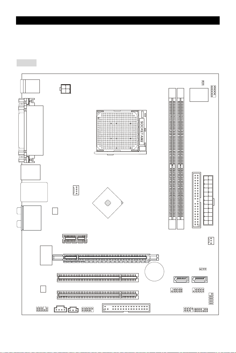
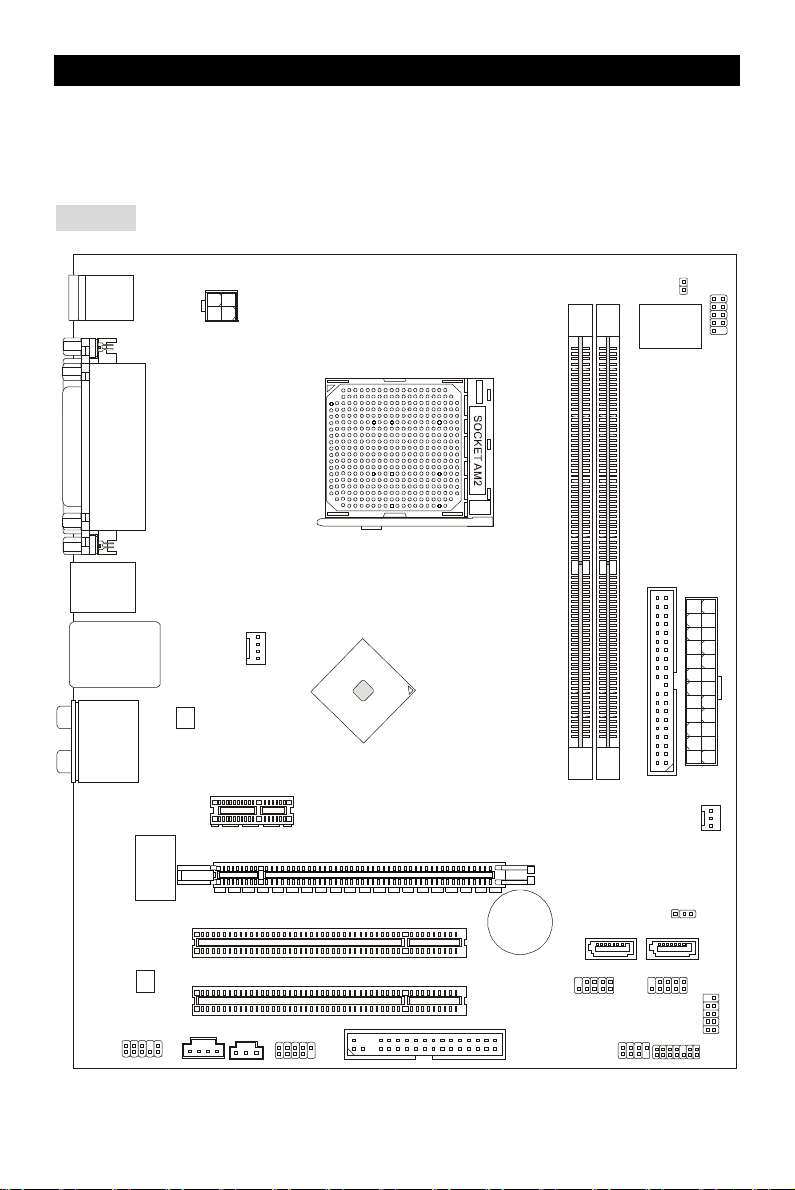
Thank you for choosing the K9N6PGM2 series (MS-7309 v1.x) Micro-ATX mainboard. The
K9N6PGM2 series is design based on MCP(P)61 / MCP(S)61 / MCP(V)61 chipset for optimal
system efficiency. Supports the AMD® Socket-AM2 processor, the K9N6GM series delivers a
high performance and professional desktop platform solution.
Layout
Top : mouse
Bottom:
keyboard
Top :
Parallel Port
Bottom:
COM 1
VGA port
Top:1394(optional)
Bottom: USB ports
Top: LAN Jack
Bottom: USB ports
T:
Line-In
M:
Line-Out
B:
Mic
T:RS-Out
M:CS-Out
B:SS-Out
RTL8201CL
/RT8211BL
(optional)
VIA
VT6308P
(optional)
JPW1
CPUFAN1
PCI _E1
PCI _E2(optional)
MCP61
1
I
P
S
J
2
1
M
M
M
M
I
I
D
D
ALC883/861
JCD1
PCI1
PCI2
SPDOUT1
J1394_1
+
JFP2
1
Page 9

Specifications
Processor Support
• Supports Socket AM2 for AMD Sempron , Athlon 64 and Athlon 64 X2
• Supports Socket AM2+ 95W processor only
(For the latest information about CPU, please visit
http://global.msi.com.tw/index.php?func=cpuform )
Chipset
• nVIDIA MCP61(P) / MCP61(S) / MCP61(V)
Memory Support
• DDRII 533/667/800 SDRAM (2GB Max)
• 2 DDRII DIMMs (240pin / 1.8V)
• Dual channel
(For the updated supporting memory modules, please visit
http://global.msi.com.tw/index.php?func=testreport )
LAN
• Supports 10/100 LAN by Realtek 8201CL (K9N6SGM-V, K9N6VGM-V)
• Supports 10/100/1000 LAN by Realtek 8211BL-GR (K9N6PGM2)
Audio
• 7.1 channel audio codec Realtek ALC888 (optional)
• 7.1 channel audio codec Realtek ALC883 (optional)
• 7.1 channel audio codec Realtek ALC861 (optional)
IDE
• 1 IDE controller on the nVIDIA MCP61 chipset provides IDE HDD/ CD-ROM with PIO, Bus
Master and Ultra DMA 133/100/66 operation modes
• Can connect up to 2 IDE devices
SATA
• Supports 2 SATAII ports with up to 3Gb/s transfer rate
• Supports up to 2 SATAII HD
RAID
• Supports RAID 0, 1
Floppy
• 1 floppy port
• Supports 1 FDD with 360K, 720K, 1.2M, 1.44M and 2.88Mbytes
Connectors
• External:
- 1 x PS/2 mouse connector
2
Page 10

- 1 x PS/2 keyboard connector
- 1 x Parallel port
- 1 x COM port
- 1 x VGA port
- 4 x USB connectors
- 1 x RJ-45 connector
- 6 x Audio jack
• Internal:
- 2 x Front USB pin-head (4 ports)
- 1 x Chassis Intrusion Switch connector
- 1 x Intel® Front Audio pin-head
- 1 x CD-in connector
- 1 x SPDIF-OUT connector
Slots
• 1 PCI Express x16 slot (K9N6PGM2)
• 1 PCI Express x16 slot but only provides x8 bandwidth (K9N6SGM-V)
• 1 PCI Express x1 slot
• 2 PCI slots (support 3.3V/ 5V PCI bus Interface)
MSI Reminds You...
K9N6SGM-V does not support ATI X550, X700, X800, X850 and X1800XL series graphic cards
Form Factor
• Micro-ATX (24.4cm X 20.5cm)
Mounting
• 6 mounting holes
3
Page 11

Correct CPU
Rear Panel
USB ports
Line ln
MIC
VGA port
1394 port
RS
SS
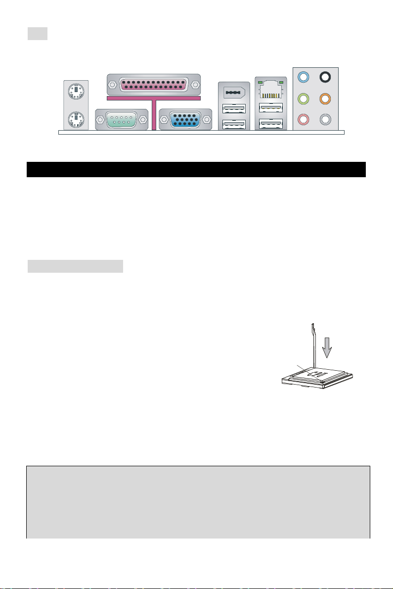
The rear panel provides the following connectors:
Mouse
Parallel
(optional)
LAN
Keyboard
COM port
Line Out
CS
Hardware Setup
This chapter tells you how to install the CPU, memory modules, and expansion cards, as well as
how to setup the jumpers on the mainboard. It also provides the instructions on connecting the
peripheral devices, such as the mouse, keyboard, etc. While doing the installation, be careful in
holding the components and follow the installation procedures.
(For the latest information about CPU, please visit:
http://global.msi.com.tw/index.php?func=cpuform)
Central Processing Unit: CPU
The mainboard supports AMD® Athlon64 X2 / Athlon64 / Sempron processors. The mainboard
uses a CPU socket called Socket AM2(940-pin) for easy CPU installation.
CPU Installation Procedures for Socket AM2
1. Please turn off the power and unplug the power cord before
installing the CPU.
2. Pull the lever sideways away from the socket. Make sure to raise
the lever up to a 90-degree angle.
3. Look for the gold arrow on the CPU. The CPU can only fit in the
correct orientation. Lower the CPU down onto the socket.
4. If the CPU is correctly installed, the pins should be completely embedded into the socket and
can not be seen. Please note that any violation of the correct installation procedures may
cause permanent damages to your mainboard.
5. Press the CPU down firmly into the socket and close the lever. As the CPU is likely to move
while the lever is being closed, always close the lever with your fingers pressing tightly on top
of the CPU to make sure the CPU is properly and completely embedded into the socket.
MSI Reminds You...
Overheating
Overheating will seriously damage the CPU and system; always make sure the cooling fan can
work properly to protect the CPU from overheating.
Overclocking
Gold arrow
placement
4
Page 12
This motherboard is designed to support overclocking. However, please make sure your
components are able to tolerate such abnormal setting, while doing overclocking. Any attempt to
operate beyond product specifications is not recommended. We do not guarantee the damages
or risks caused by inadequate operation or beyond product specifications.
CPU and Cooler Installation
When you are installing the CPU, make sure the CPU has a cooler attached on the top to prevent
overheating. If you do not have the cooler, contact your dealer to purchase and install them
before turning on the computer. Meanwhile, do not forget to apply some silicon heat transfer
compound on CPU before installing the cooler for better heat dispersion.
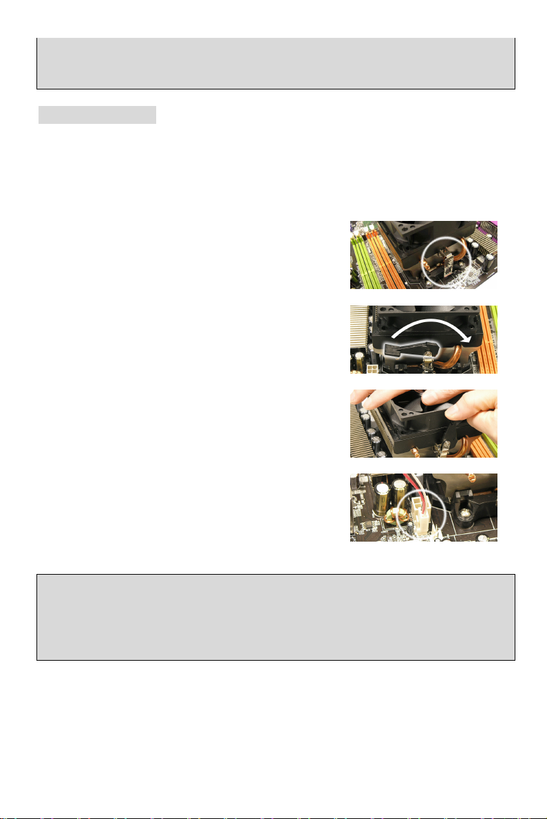
Follow the steps below to install the CPU & cooler correctly. Wrong installation will cause the
damage of your CPU & mainboard.
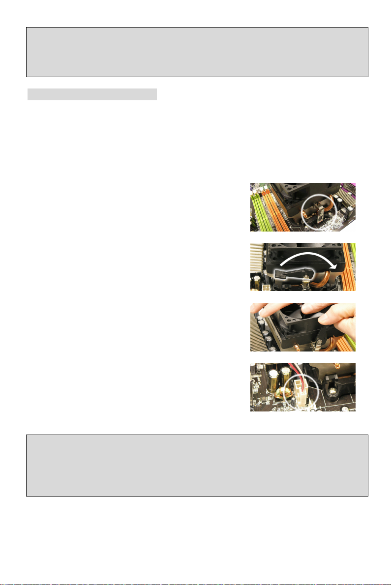
1. Position the cooling set onto the retention mechanism.
Hook one end of the clip to hook first.
2. Then press down the other end of the clip to fasten the
cooling set on the top of the retention mechanism.
Locate the Fix Lever and lift up it.
3. Fasten down the lever.
4. Attach the CPU Fan cable to the CPU fan connector on
the mainboard.
MSI Reminds You...
1. Confirm if your CPU cooler is firmly installed before turning on your system.
2. Check the information in PC Health Status of H/W Monitor in BIOS for the CPU temperature.
3. Please note that the mating/unmating durability of the CPU is 20 cycles. Therefore we suggest
you do not plug/unplug the CPU too often.
5
Page 13
Memory
Notch
Volt
GND
GND
GND
GND
GND
PS-ON#
PWR OK
The mainboard provides two 240-pin DIMM slots for unbuffered DDR II 533 / 667 / 800 SDRAM
(DDR II 800 is only for Athlon 64 X2). To operate properly, at least one DIMM slot must be
installed.
Install at least one Memory module on one of the slots. Memory modules can be installed on the
slots in any order. You can install either single- or double-sided modules to meet your own needs.
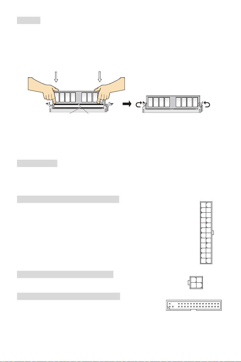
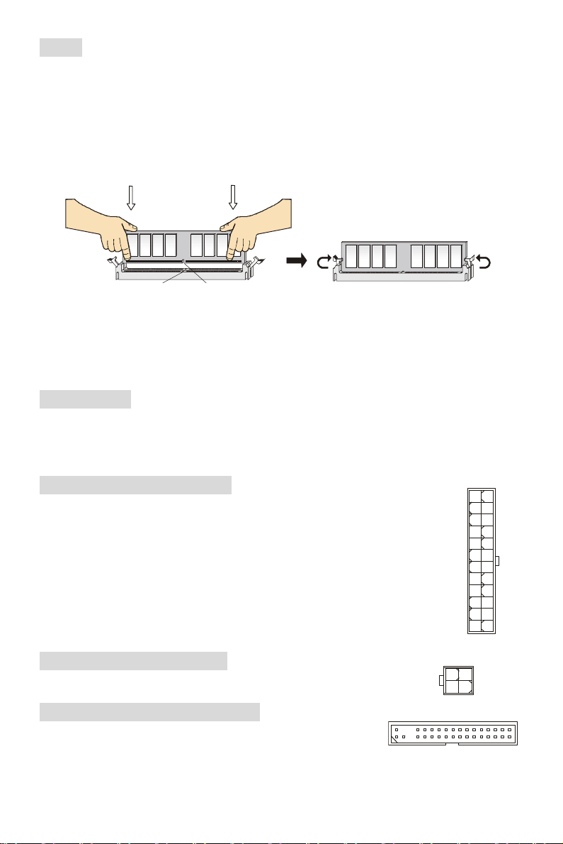
Installing DDR II Modules
1. The DDR II DIMM has only one notch on the center of slot. The memory module will only fit in
the right orientation.
2. Insert the memory module vertically into the DIMM slot. Then push it in until the golden finger
on the memory module is deeply inserted in the socket.
3. The plastic clip at each side of the DIMM slot will automatically close.
Power Supply
The mainboard supports ATX power supply for the power system. Before inserting the power
supply connector, always make sure that all components are installed properly to ensure that no
damage will be caused. A 300W or above power supply is suggested.
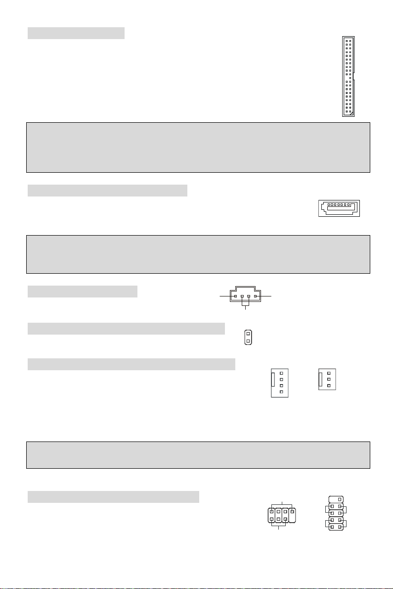
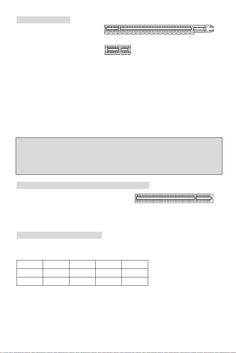
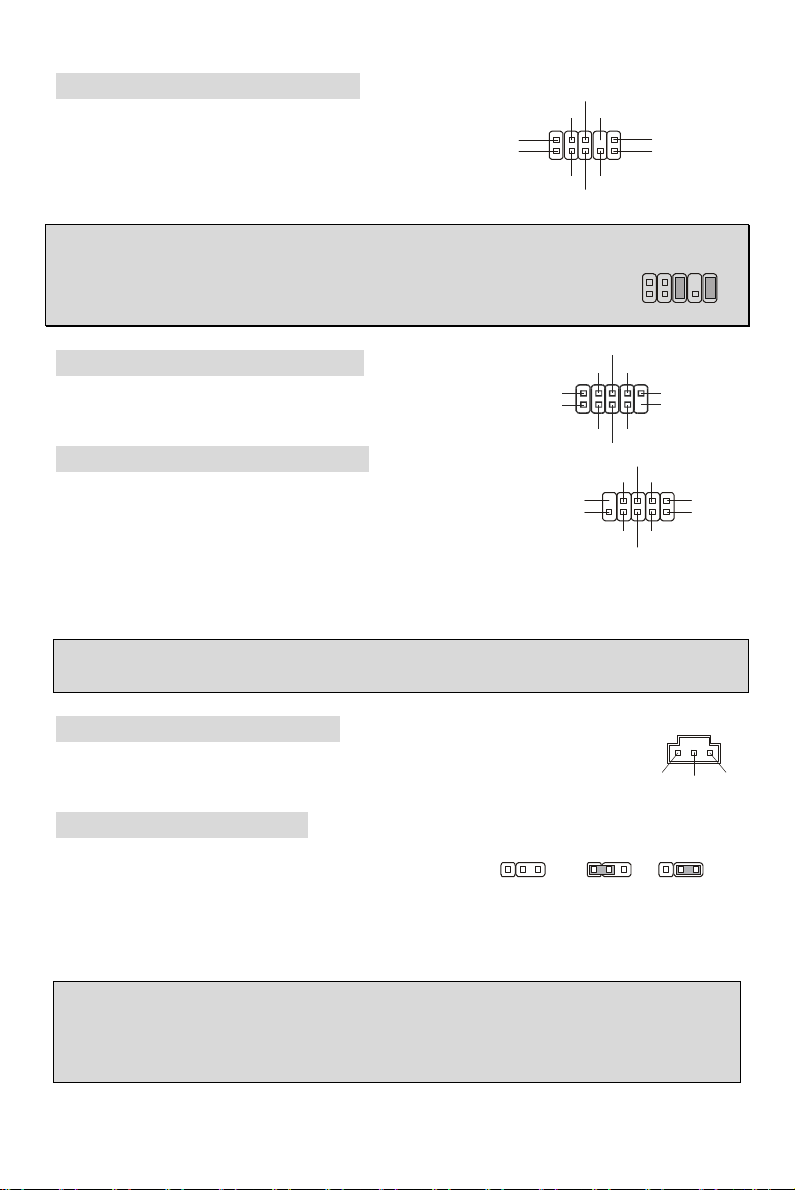
ATX 24-Pin Power Connector: ATX1
This connector allows you to connect an ATX 24-pin power supply. To
connect the ATX 24-pin power supply, make sure the plug of the power
supply is inserted in the proper orientation and the pins are aligned. Then
push down the power supply firmly into the connector.
You may use the 20-pin ATX power supply as you like. If you’d like to use the
20-pin ATX power supply, please plug your power supply along with pin 1 &
pin 13. There is also a foolproof design on pin 11, 12, 23 & 24 to avoid wrong
installation.
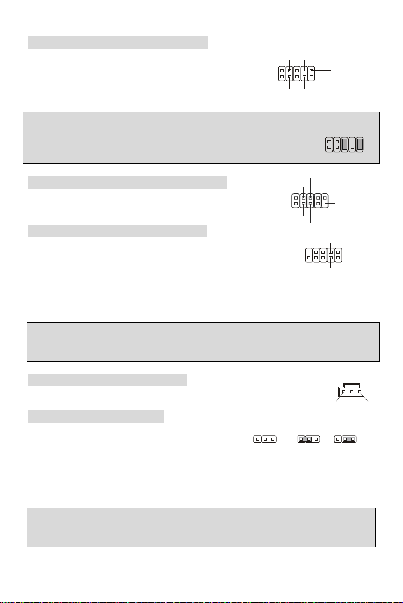
ATX 12V Power Connector: JPW1
This 12V power connector is used to provide power to the CPU.
+12V
+12V
+3.3V
+12V
+12V
5VSB
GND
+5V
GND
+5V
GND
+3.3V
+3.3V
+5V
+5V
+5V
Res
GND
GND
-12V
+3.3V
Floppy Disk Drive Connector: FDD1
The mainboard provides a standard floppy disk drive connector that
supports 360K, 720K, 1.2M, 1.44M and 2.88M floppy disk types.
6
Page 14
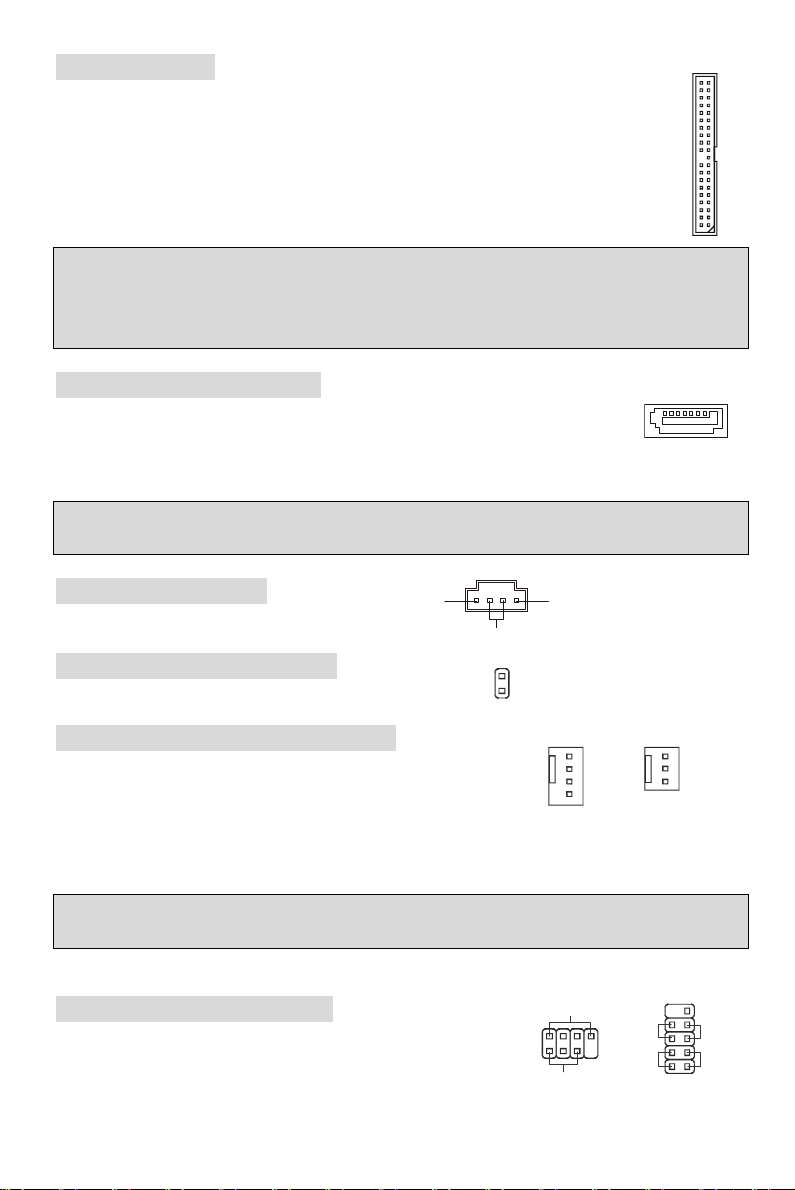
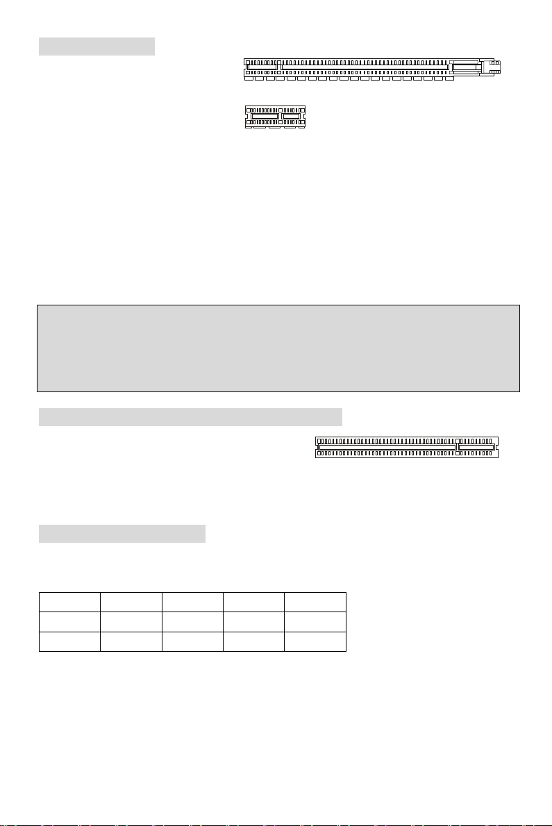
IDE Connector: IDE1
L
GND
+12V
Sensor
+12V
Sensor
Control
Speaker
817
JFP2
Reset
1910
+
JFP1
The mainboard has dual Ultra DMA 66/100/133 controller that provides PIO mode 0~4,
Bus Master, and Ultra DMA 66/100/133 function. You can connect up to two hard disk
drives, CD-ROM, 120MB Floppy and other devices.
The first hard drive should always be connected to IDE1. IDE1 can connect a Master
and a Slave drive. You must configure second hard drive to Slave mode by setting the
jumper accordingly.
MSI Reminds You...
If you install two hard disks on one cable, you must configure the second drive to Slave mode by
setting its jumper. Refer to the hard disk documentation supplied by hard disk vendors for jumper
setting instructions.
Serial ATAII Connectors: SATA1~2
SATA 1, 2 are dual high-speed Serial ATA interface ports. Each supports 2nd
generation serial ATA data rates of 300 MB/s. All connectors are fully compliant
with Serial ATA 2.0 specifications. Each Serial ATAII connector can connect to 1 hard disk device.
MSI Reminds You...
Please do not fold the serial ATA cable in a 90-degree angle, which will cause the loss of data
during transmission.
CD In Connector: JCD1
The connector is for CD-ROM audio connector.
R
Chassis Intrusion Switch Connector: JCI1
This connector is connected to a 2-pin chassis switch.
Fan Power Connectors: CPUFAN1/SYSFAN1
The 4-pin CPUFAN1 (processor fan) and 3-pin SYSFAN1 (system
fan) support system cooling fan with +12V. When connecting the
wire to the connectors, always take note that the red wire is the
positive and should be connected to the +12V, the black wire is Ground and should be connected
to GND. If the mainboard has a System Hardware Monitor chipset on-board, you must use a
specially designed fan with speed sensor to take advantage of the CPU fan control.
MSI Reminds You...
Always consult the vendors for the proper CPU cooling fan.
1
2
CINTRU
GND
GND
GND
Front Panel Connectors: JFP1, JFP2
The mainboard provides a front panel connector for electrical
connection to the front panel switches and LEDs. JFP1 is
compliant with Intel® Front Panel I/O Connectivity Design Guide.
7
2
Power LED
Power
Switch
Power
LED
+
+
-
Switch
-
HDD
LED
2
Page 15
VCC(2)
USB0+
USB1+
VCC(1)
AUD_RET_R
AUD_RET_L(10)
AUD_FPOUT_L(9)
9210
GND
SPDIF
TPB-
Cable power
TPB+
Cable power
Key,no pin(9)
Keep Data
Clear Data
222333111
Front Panel Audio Connector: JAUD1
The front panel audio connector allows you to
connect to the front panel audio and is compliant
with Intel® Front Panel I/O Connectivity Design
Guide.
(2)AUD_GND
(1)AUD_MIC
AUD_VCC
AUD_MIC_BIAS
MSI Reminds You...
If you do not want to connect to the front audio header, pins 5 & 6, 9 & 10 have
to be jumpered in order to have signal output directed to the rear audio ports.
Otherwise, the Line-Out connector on the back panel will not function.
Key
HP_ON
AUD_FPOUT_R
1
(9)Key
GND
GND
GND
GND(10)
USB0-
USB1-GND
IEEE 1394 Connector: J1394_1 (Optional)
The 1394 pin header allows you to connect IEEE 1394 ports
via an external IEEE1394 bracket (optional)
(2)TPA-
(1)TPA+
Front USB Connector: JUSB1/JUSB2
The mainboard provides three standard USB 2.0 pin headers
JUSB1 and JUSB2. USB2.0 technology increases data
transfer rate up to a maximum throughput of 480Mbps, which
is 40 times faster than USB 1.1, and is ideal for connecting
high-speed USB interface peripherals such as USB HDD, digital cameras, MP3 players, printers,
modems, etc.
MSI Reminds You...
Please note that the pins of VCC & GND must be connected correctly or it may cause some
damage
(10)USB0C
SPDIF-Out Connector: SPDOUT1
This connector is used to connect SPDIF interface for digital audio transmission.
VCC
Clear CMOS Jumper: JBAT1
There is a CMOS RAM on board that has a power supply
from external battery to keep the data of system
configuration. With the CMOS RAM, the system can
automatically boot OS every time it is turned on. If you want to clear the system configuration,
use the JBAT1 (Clear CMOS Jumper) to clear data. Follow the instructions below to clear the
data:
MSI Reminds You...
You can clear CMOS by shorting 2-3 pin while the system is off. Then return to 1-2 pin position.
Avoid clearing the CMOS while the system is on; it will damage the mainboard.
8
Page 16
PCI Express Slots
The PCI Express slots, as a
high-bandwidth, low pin count, serial,
interconnect technology.
PCI Express architecture provides a
high performance I/O infrastructure for
Desktop Platforms with transfer rates
starting at 2.5 Giga transfers per second over a PCI Express x1 lane for Gigabit Ethernet, TV
Tuners, 1394 controllers, and general purpose I/O. Also, desktop platforms with PCI Express
Architecture will be designed to deliver highest performance in video, graphics, multimedia and
other sophisticated applications. Moreover, PCI Express architecture provides a high
performance graphics infrastructure for Desktop Platforms doubling the capability of existing
AGP 8x designs with transfer rates of 4.0 GB/s over a PCI Express x16 lane for graphics
controllers.
You can insert the expansion cards to meet your needs. When adding or removing expansion
cards, make sure that you unplug the power supply first.
Note:
System default is to disable the onboard VGA when you insert a PCI-E graph card, in order to
optimize the system performance. If you would like to use both onboard and expansion card
graph functions, you have to enter the mainboard BIOS and select Advanced Chipset Features
-> OnChip and PCIe VGA selection -> Both exist and Oncip VGA by frame buffer select.
PCI Express X16 Slot
PCI Express X1 Slot
PCI (Peripheral Component Interconnect) Slots
The PCI slots allow you to insert the expansion cards
to meet your needs. When adding or removing
expansion cards, make sure that you unplug the power supply first. Meanwhile, read the
documentation for the expansion card to make any necessary hardware or software settings for
the expansion card, such as jumpers, switches or BIOS configuration.
PCI Interrupt Request Routing
The IRQ, abbreviation of interrupt request line and pronounced I-R-Q, are hardware lines over
which devices can send interrupt signals to the microprocessor. The PCI IRQ pins are typically
connected to the PCI bus INT A# ~ INT D# pins as follows:
Order1 Order2 Order3 Order4
PCI Slot 1 INT B# INT C# INT D# INT A#
PCI Slot 2 INT C# INT D# INT A# INT B#
9
Page 17
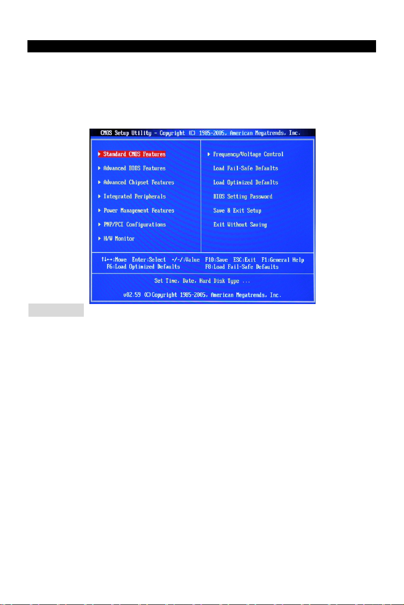
BIOS Setup
Power on the computer and the system will start POST (Power On Self Test) process. When the
message below appears on the screen, press <DEL> key to enter Setup.
DEL: Setup F11: Boot Menu TAB: Logo
If the message disappears before you respond and you still wish to enter Setup, restart the
system by turning it OFF and On or pressing the RESET button. You may also restart the system
by simultaneously pressing <Ctrl>, <Alt>, and <Delete> keys.
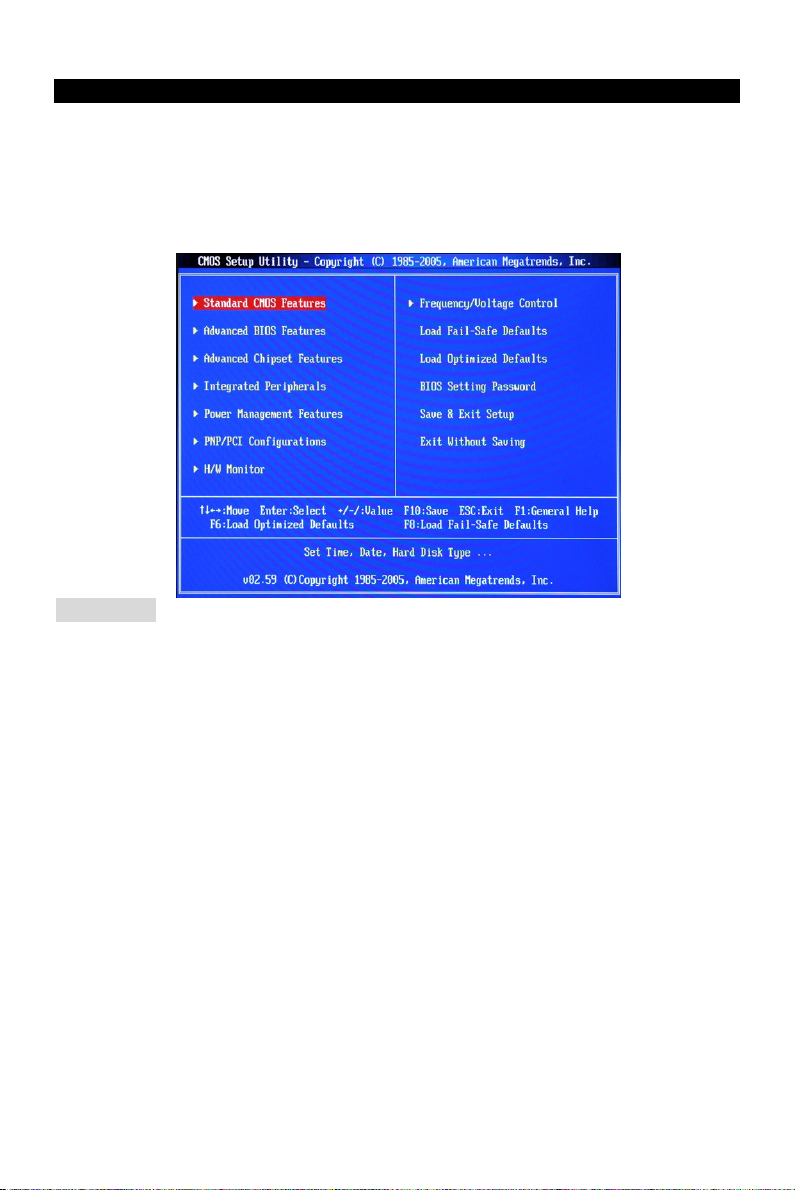
Main Page
Standard CMOS Features
Use this menu for basic system configurations, such as time, date etc.
Advanced BIOS Features
Use this menu to setup the items of Award special enhanced features.
Advanced Chipset Features
Use this menu to change the values in the chipset registers and optimize your system
performance.
Integrated Peripherals
Use this menu to specify your settings for integrated peripherals.
Power Management Features
Use this menu to specify your settings for power management.
PNP/PCI Configurations
This entry appears if your system supports PnP/PCI.
H/W Monitor
This entry shows the status of your CPU, fan, warning for overall system status.
Frequency/Voltage Control
Use this menu to specify your settings for frequency/voltage control.
Load Fail-Safe Defaults
Use this menu to load the BIOS default values that are factory settings for system operations.
10
Page 18
Load Optimized Defaults
Use this menu to load factory default settings into the BIOS for stable system performance
operations.
BIOS Setting Password
Use this menu to set BIOS setting Password.
Save & Exit Setup
Save changes to CMOS and exit setup.
Exit Without Saving
Abandon all changes and exit setup.
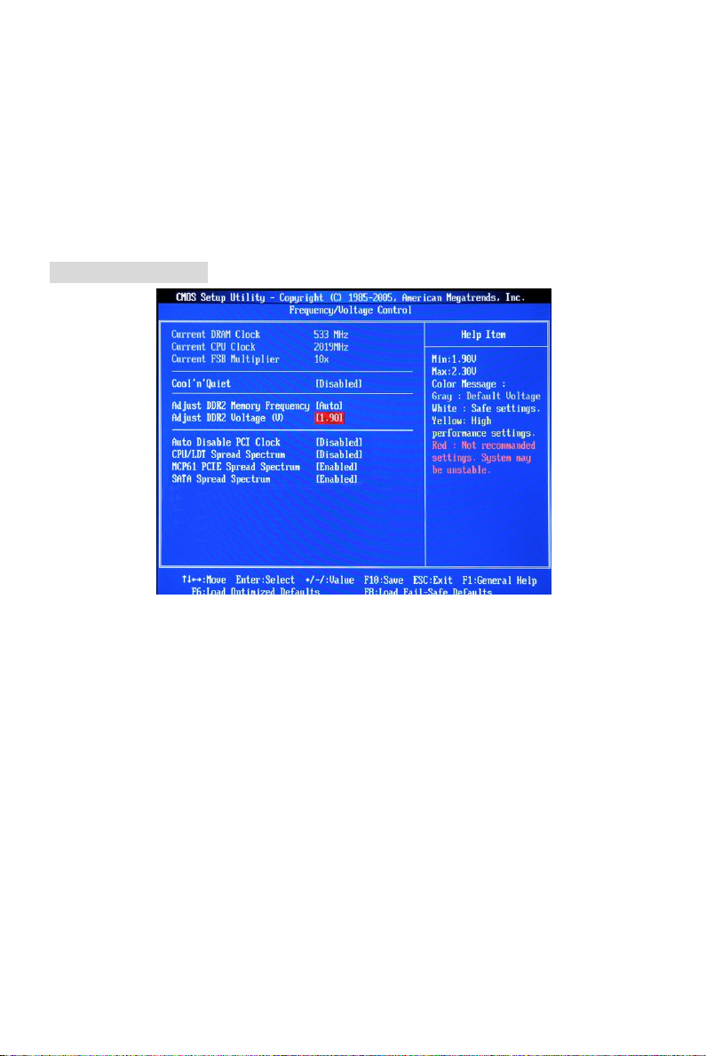
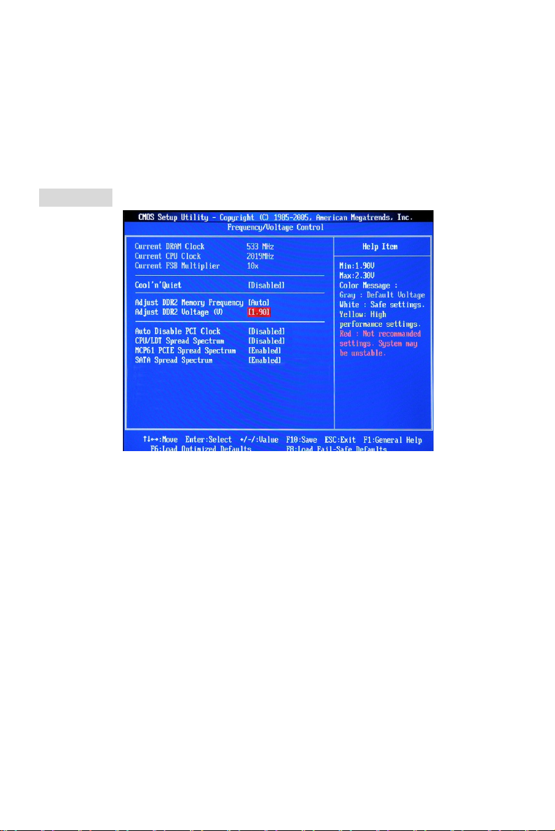
Frequency/Voltage
Current DRAM Clock
It shows the current clock of memory. Read-only.
Current CPU Clock
It shows the current clock of CPU. Read-only.
Current FSB Multiplier
It shows the current Front Side Bus Multiplication. Read-only.
Cool’n’Quiet
This feature is especially designed for AMD processor, which provides a CPU temperature
detecting function to prevent your CPU from overheating due to the heavy working loading.
Adjust DDR2 Memory Frequency
This item allows you to select the memory frequency programming method. If select Auto, the
memory speed will be based on SPDs. If select Limit, the memory speed will not exceed the
specified value. If select Manual, the memory specified will be programmed regardless of SPD.
Adjust DDR2 Voltage (V)
Adjusting the voltage of the memory can increase the speed. Any changes made to this setting
may cause a stability issue, so changing the voltage for long-term purpose is NOT
recommended.
11
Page 19

Auto Disable PCI Clock
This item is used to auto disable the PCI slots. When set to [Enabled], the system will remove
(turn off) clocks from empty PCI slots to minimize the electromagnetic interference (EMI).
CPU/LDT Spread Spectrum
This setting is used to enable or disable the CPU/LDT (HT Bus multiplier) Spread Spectrum
feature.
MCP61 PCIE Spread Spectrum
This setting is used to enable or disable the MCP61 PCIE Spread Spectrum feature.
SATA Spread Spectrum
This setting is used to enable or disable the SATA Spread Spectrum feature.
MSI Reminds You...
1 .If you do not have any EMI problem, leave the setting at [Disabled] for optimal system stability
and performance. But if you are plagued by EMI, select the value of Spread Spectrum for EMI
reduction.
2. The greater the Spread Spectrum value is, the greater the EMI is reduced, and the system will
become less stable. For the most suitable Spread Spectrum value, please consult your local EMI
regulation.
3. Remember to disable Spread Spectrum if you are overclocking because even a slight jitter can
introduce a temporary boost in clock speed which may just cause your overclocked processor to
lock up.
Load Optimized Defaults
You can load the default values provided by the mainboard manufacturer for the stable
performance.
12
Page 20
소개
I
D
E
1
JCI1
A
TX1
JAUD1
SATA1
SATA2
JBAT1
JUSB2
JUSB1
JLPC1
JFP
1
S
Y
S
F
A
N
1
(optional)
BATT
FDD 1
nVIDIA
K9N6PGM2 시리즈 (MS-7309 v1.X) Micro-ATX 메인보드를 선택해주셔서 감사합니다.
K9N6PGM2 시리즈는 최적의 시스템 효율을 위해 MCP(P)61 / MCP(S)61 / MCP(V)61 칩셋을
기반으로 디자인했습니다. AMD® Socket-AM2 프로세서를 지원하는 K9N6GM 시리즈는
고성능 및 전문적인 데스크톱 플랫폼 솔루션을 제공합니다.
레이아웃
Top : mouse
Bottom:
keyboard
Top :
Parallel Port
Bottom:
COM 1
VGA port
Top:1394(optional)
Bottom: USB ports
Top: LAN Jack
Bottom: USB ports
T:
Line-In
M:
Line-Out
B:
Mic
T:RS-Out
M:CS-Out
B:SS-Out
RTL8201CL
/RT8211BL
(optional)
VIA
VT6308P
(optional)
JPW1
CPUFAN1
PCI _E1
PCI _E2(optional)
MCP61
1
I
P
S
J
2
1
M
M
M
M
I
I
D
D
ALC883/861
JCD1
PCI1
PCI2
SPDOUT1
J1394_1
+
JFP2
13
Page 21

사양
지원되는 프로세서
• AMD Sempron, Athlon 64 및 Athlon 64 X2 용 Socket AM2 지원
• Socket AM2+ 95W 프로세서만 지원
(CPU에 대한 최신 정보는 http://global.msi.com.tw/index.php?func=cpuform 를 참조하십시오.)
칩셋
• nVIDIA MCP61(P)/MCP61(S)/MCP61(V)
지원되는 메모리
• DDRII 533/667/800 SDRAM(최대 2GB)
• 2개의 DDRII DIMM(240핀/1.8V)
• 듀얼 채널:
(업데이트된 지원 메모리 모듈은 http://global.msi.com.tw/index.php?func=testreport 를
참조하십시오.)
LAN
• Realtek 8201CL 에 의한 10/100 LAN(K9N6SGM-V, K9N6VGM-V) 지원
• Realtek 8211BL-GR 에 의한 10/100/1000(K9N6PGM2) 지원
오디오
• 7.1 채널 오디오 코덱 Realtek ALC888(옵션)
• 7.1 채널 오디오 코덱 Realtek ALC883(옵션)
• 7.1 채널 오디오 코덱 Realtek ALC861(옵션)
IDE
• nVIDIA MCP61 칩셋의 IDE 컨트롤러가 IDE HDD/ CD-ROM 에 PIO, 버스 마스터 및
Ultra DMA 133/100/66 작동 모드를 제공
• 최대 2대의 IDE 장치 연결 가능
SATA
• 최대 전송률 3Gb/s 의 2 SATAII 포트 지원
• 최대 2개의 SATAII HD 지원
RAID
• RAID 0, 1 지원
플로피
• 플로피 포트 1개
• 360KB, 720KB, 1.2MB, 1.44M 및 2.88MB 의 FDD 1개 지원
커넥터
• 외부:
14
Page 22

- PS/2 마우스 커넥터 1개
- PS/2 키보드 커넥터 1개
- 병렬 포트 1개
- COM 포트 1개
- VGA 포트 1 개
- USB 커넥터 4개
- RJ-45 커넥터 1개
- 오디오 잭 6개
• 내부:
- 전면 USB 핀 헤드 2개(포트 4개)
- 섀시 침입 스위치 커넥터 1개
- Intel® 전면 오디오 핀 헤드 1개
- CD 입력 커넥터 1개
- SPDIF 출력 커넥터 1개
슬롯
• PCI Express x16 슬롯(K9N6PGM2) 1개
• PCI Express x16 슬롯(K9N6SGM-V) 1 개(x8 대역폭만 지원)
• PCI Express x1 슬롯 1개
• PCI 슬롯 2개(3.3V/5V PCI 버스 인터페이스 지원)
MSI의 주의 사항...
K9N6SGM-V는 ATI X550, X700, X800, X850 및 X1800XL
않습니다
.
폼 팩터
• Micro-ATX(24.4cm X 20.5cm)
장착
• 장착 구멍 6개
15
시리즈 그래픽 카드를 지원하지
Page 23
Correct CPU
뒷면
USB ports
Line ln
MIC
VGA port
1394 port
RS
SS
뒷면에는 다음 커넥터가 있습니다.
Mouse
Keyboard
하드웨어 설치
COM port
Parallel
(optional)
LAN
Line Out
CS
이 장에서는 CPU, 메모리 모듈, 확장 카드의 설치 방법과 메인보드의 점퍼 설정 방법을
설명합니다. 또한 마우스, 키보드 등과 같은 주변 장치의 연결 방법을 설명합니다. 설치하는
동안, 부품을 주의해서 취급하고 설치 절차를 잘 따르십시오.
(CPU 에 대한 최신 정보는
http://www.msi.com.tw/program/products/mainboard/mbd/pro_mbd_cpu_support.php 를
참조하십시오.)
중앙 처리 장치: CPU
이 메인보드는 AMD® Athlon64 X2/Athlon64/Sempron 프로세서를 지원합니다. 이 메인보드는
CPU 를 쉽게 설치하기 위해 Socket AM2(940 핀)라고 부르는 CPU 소켓을 사용합니다.
Socket AM2용 CPU 설치 절차
1. CPU 를 설치하기 전에 전원을 끄고 전원 코드를 뽑습니다.
2. 레버를 소켓에서 비스듬히 당깁니다. 레버를 90도까지
올립니다.
3. CPU 의 금색 화살표를 찾습니다. CPU 는 올바른 한 쪽
Gold arrow
placement
방향으로만 끼워집니다. CPU 를 소켓 위에 내려 맞춥니다.
4. CPU 가 올바로 설치되면, 핀이 소켓에 완전히 끼워져서 보이지
않게 됩니다. 올바른 설치 절차를 따르지 않으면 메인보드가 영구적으로 손상될 수
있습니다.
5. CPU 를 소켓 안으로 꽉 눌러 넣고 레버를 닫습니다. 레버를 닫는 동안 CPU 가 움직일
우려가 있기 때문에, 레버를 닫을 때는 항상 손가락으로 CPU 의 상단을 꽉 눌러 CPU 가
소켓 안에 제대로 완전히 끼워지도록 해야 합니다.
MSI의 주의 사항...
과열
과열되면
CPU가
작동하는지 항상 확인하십시오
오버클로킹
이 메인보드는 오버클로킹을 지원하도록 디자인되었습니다. 그러나 오버클로킹이 진행되는
심각하게 손상될 수 있습니다
.
. CPU가
과열되지 않도록 냉각 팬이 제대로
16
Page 24
동안 부품이 이러한 비정상적인 설정을 견뎌낼 수 있는지 확인하십시오. 제품 사양을
초과하는 범위에서 작동시키지 마십시오. 당사는 올바르지 않은 작동이나 제품 사양을
초과한 범위에서 사용하여 발생한 손상 또는 위험은 보증하지 않습니다
CPU 및 쿨러 설치
CPU 설치 시 과열을 방지하는 쿨러를 상단에 연결하십시오. 쿨러가 없는 경우, 컴퓨터를
켜기 전에 판매점에 문의하여 쿨러를 구입하여 설치하십시오. 한편, 열이 잘 발산되도록
쿨러를 설치하기 전에 CPU 에 실리콘 열 전달 컴파운드를 약간 바르십시오.
아래의 단계에 따라 CPU 및 쿨러를 올바로 설치하십시오. 잘못 설치할 경우 CPU 와
메인보드가 손상됩니다.
1. 쿨러 세트를 고정 위치에 올려놓습니다. 먼저 클립의
한쪽 끝을 사용하여 겁니다.
2. 그리고 나 서 클립의 다른 쪽 끝을 눌러 쿨러 세트를
고정 위치의 상단에 고정합니다. 고정 레버를 찾아
위로 올립니다.
3. 레버를 아래로 눌러 고정합니다.
.
4. CPU 팬 케이블을 메인보드의 CPU 팬 커넥터에
연결합니다.
MSI의 주의 사항...
1.
시스템을 켜기 전에
2. BIOS의 H/W
3. CPU의 체결/체결 해제
빼지 마십시오
CPU
모니터의
.
쿨러가 단단히 설치되었는지 확인합니다
PC 상태
내구성은
정보에서
20
CPU
회입니다. 따라서
온도를 확인하십시오
17
CPU의
.
.
플러그를 너무 자주 꽂거나
Page 25
메모리
Notch
Volt
GND
GND
GND
PS-ON#
PWR OK
GND
GND
이 메인보드는 언버퍼드 DDR II 533/667/800 SDRAM용 240 핀 DIMM 슬롯을
제공합니다(DDR II 800은 Athlon 64 X2 전용임). 제대로 작동하려면, 최소 1개의 DIMM
슬롯이 설치되어 있어야 합니다.
최소 1개의 메모리 모듈을 슬롯 중 하나에 설치 하십시오. 메모리 모듈을 어떤 순서로
슬롯에 설치하든 상관없습니다. 사용자의 필요에 따라 단면 모듈 또는 양면 모듈을 설치할
수 있습니다.
DDR II 모듈 설치 방법
1. DDR II DIMM 에는 슬롯 중앙에 노치가 하나 밖에 없습니다. 메모리 모듈은 오른쪽
방향으로만 끼워집니다.
2. 메모리 모듈을 DIMM 슬롯에 수직으로 끼웁니다. 그리고 나서 메모리 모듈 위의 골든
핑거가 소켓에 깊이 삽입될 때까지 밀어 넣습니다.
3. DIMM 슬롯의 양쪽에 있는 플라스틱 클립이 자동으로 닫힙 니다.
전원 공급장치
이 메인보드는 전원 시스템용으로 ATX 전원 공급장치를 지원합니다. 전원 공급장치
커넥터를 끼우기 전에, 손상이 발생하지 않도 록 모든 컴포넌트가 제대로 설치되었는지
확인하십시오. 300W 이상의 전원 공급장치를 권장합니다.
ATX 24 핀 전원 커넥터: ATX1
이 커넥터를 사용하여 ATX 24 핀 전원 공급장치를 연결 할 수 있습니다.
ATX 24 핀 전원 공급장치를 연결하려렴, 전원 공급장치의 플러그가
올바른 방향으로 삽입되었는지, 핀이 정렬되었는지 확인하십시오. 그리고
나서 전원 공급장치를 커넥터 안쪽으로 꽉 맞게 누릅니다.
원하는 경우 20 핀 ATX 전원 공급장치를 사용할 수 있습니다. 20 핀 ATX
전원 공급장치를 사용하려면, 전원 공급장치의 플러그를 핀 1 및 핀
13 과 함께 연결하십시오. 핀 11, 12, 23 및 24 의 디자인은 누구나 쉽게
알 수 있어서 잘못 설치할 염려가 없습니다.
ATX 12V 전원 커넥터: JPW1
12V 전원 커넥터는 CPU 에 전원을 공급하는 데 사용됩니다.
+12V
+12V
+3.3V
+12V
+12V
5VSB
GND
+5V
GND
+5V
GND
+3.3V
+3.3V
+5V
+5V
+5V
Res
GND
GND
-12V
+3.3V
플로피 디스크 장치 커넥터: FDD1
이 메인보드는 360KB, 720KB, 1.2MB, 1.44MB 및 2.88MB
플로피 디스크 타입을 지원하는 표 준 플로피 디스크 드라이브를
제공합니다.
18
Page 26
IDE 커넥터: IDE1
L
GND
+12V
Sensor
+12V
Sensor
Control
Speaker
817
JFP2
Reset
1910
+
JFP1
이 메인보드에는 PIO 모드 0~4, 버스 마스터 및 Ultra DMA 66/100/133 기능을
제공하는 듀얼 Ultra DMA 66/100/133 컨트롤러가 있습니다. 최대 2대의 하드
디스크 드라이브, CD-ROM, 120MB 플로피 및 기타 장치를 연결할 수 있습니다.
첫 번째 하드 드라이브는 항상 IDE1 에 연결해야 합니다. IDE1 은 마스터
드라이브와 슬레이브 드라이브를 연결 합니다. 점퍼를 적절하게 설정하여 두 번째
하드 드라이브를 슬레 이브 모드로 구성할 수 있습니다.
MSI의 주의 사항...
동일한 케이블에 2개의
슬레이브 모드로 구성해야 합니다. 점퍼 설정 방법은 하드 디스크 공급업체가 제공한 하드
디스크의 설명서를 참조하십시오
IDE
장치를 설치하는 경우, 점퍼를 설정하여 두 번째 드라이브를
.
직렬 ATAII 커넥터: SATA1~2
SATA 1, 2 는 고속의 듀얼 직렬 ATA 인터페이스 포트입니다. 각각의 포트는
300 MB/s 의 차세대 직렬 ATA 데이터 속도를 지원합니다. 모든 커넥터는
직렬 ATA 2.0 규격을 완전히 준수합니다. 각각의 직럴 ATAII 커넥터는 하나의 하드 디스크
장치에 연결할 수 있습니다.
MSI의 주의 사항...
직렬
ATA
케이블을
CD 입력 커넥터: JCD1
이 커넥터는 CD-ROM 오디오 커넥터용입니다.
90도로 꺾지
마십시오. 그럴 경우 전송 중 데이터가 손실됩니다
R
.
섀시 침입 스위치 커넥터: JCI1
이 커넥터는 2핀 섀시 스위치에 연결됩니다.
팬 전원 커넥터: CPUFAN1/SYSFAN1
4 핀 CPUFAN1(프로세서 팬)과 3핀 SYSFAN1(시스템 팬)은
+12V 의 시스템 냉각 팬을 지원합니다. 전선을 커넥터에 연결할
때, 항상 빨간색 전선이 양극으로서 +12V 에 연결해 야 하고,
검은색 전선은 접지선으로서 GND 에 연결해야 합니다. 메인보드에 시스템 하드웨어 모니터
칩셋 온보드가 있는 경우, CPU 팬 제어를 활용하기 위해 속도 센서가 있는 특별히
디자인된 팬을 사용해 야 합니다.
MSI의 주의 사항...
올바른
CPU 냉각 팬은
반드시 공급업체에 문의하십시오
CINTRU
1
GND
2
GND
.
GND
전면 패널 커넥터: JFP1, JFP2
이 메인보드는 전면 패널 스위치 및 LED 에 대한 전기 연결용
전면 패널 커넥터를 제공합니다. JFP1 은 Intel® Front Panel I/O
Connectivity Design Guide를 준수합니다.
19
2
Power LED
Power
Switch
Power
LED
+
+
-
Switch
-
HDD
LED
2
Page 27
TPB-
Cable power
TPB+
Cable power
Key,no pin(9)
AUD_RET_R
AUD_RET_L(10)
AUD_FPOUT_L(9)
9210
VCC(2)
USB0+
USB1+
VCC(1)
GND
SPDIF
Keep Data
Clear Data
222333111
전면 패널 오디오 커넥터: JAUD1
전면 패널 오디오 커넥터를 사용하 여 전면 패널
오디오를 연결할 수 있으며, 이 커넥터는 Intel®
Front Panel I/O Connectivity Design Guide 를
준수합니다.
(2)AUD_GND
(1)AUD_MIC
AUD_VCC
AUD_MIC_BIAS
MSI의 주의 사항...
전면 오디오 헤더에 연결하려는 경우, 신호 출력을 후면 오디오 포트로 보내기 위해
핀 5와
6, 9와 10을
그러지 않을 경우, 후면 패널의 라인 출력이 작동하지 않습니다
점퍼시켜야 합니다
.
.
Key
HP_ON
AUD_FPOUT_R
1
(9)Key
GND
GND
.
GND
GND(10)
USB0-
USB1-GND
IEEE 1394 커넥터: J1394_1(옵션)
1394 핀 헤더를 사용하여 외부 IEEE 1394 브래킷(옵션)을
통해 IEEE1394 포트를 연결할 수 있습니다.
(2)TPA-
(1)TPA+
전면 USB 커넥터: JUSB1/ JUSB2
이 메인보드는 3개의 표준 USB 2.0 핀 헤더 JUSB1 및
JUSB2 를 제공합니다. USB2.0 기술은 데이터 전송률을
480Mbps 의 최대 처리량까지 증가시켰는데, 이는 USB
1.1과 비교하여 40 배가 빠른 속도로서 USB HDD, 디지털
카메라, MP3 플레이어, 프린터, 모뎀 등과 같은 고속의 USB 인터페이스 주변 장치를
연결하는 데 적합합니다.
MSI의 주의 사항...
VCC 및 GND의 핀은
손상을 방지하기 위해 올바로 연결해야 합니다
(10)USB0C
SPDIF 출력 커넥터: SPDOUT1
이 커넥터는 디지털 오디오 전송을 위해 SPDIF 인터페이스를 연결하는 데
사용됩니다.
VCC
CMOS 점퍼 지우기: JBAT1
보드에 시스템 구성 데이터를 유지하기 위해 외부
배터리로부터 전원을 공급 받은 CMOS RAM 이 있습니다.
CMOS RAM의 경우, 시스템을 켤 때마다 시스템이 OS 를
자동으로 부팅합니다. 시스템 구성을 지우려면, JBAT1(CMOS 점퍼 지우기)을 사용하여
데이터를 지우십시오. 아래 지시시항에 따라 데이터를 지우십시오.
MSI의 주의 사항...
시스템이 꺼져 있는 동안
핀 위치로 돌아가십시오. 시스템이 켜 있는 동안에는
메인보드가 손상될 수 있습니다
2-3 핀을
.
단락시켜
CMOS를 지울 수
CMOS를
있습니다. 그리고 나서
지우지 마십시오. 그럴 경우
1-2
20
Page 28
PCI Express 슬롯
고대역폭, 낮은 핀 계수, 직렬, 상호
연결 기술과 같은 PCI Express 슬롯.
PCI Express 아키텍처는 Gigabit
이더넷, TV 튜너, 1394 컨트롤러,
일반용 I/O 에 사용되는 PCI Express
x1 을 통해 최소 전송률이 초 당 2.5
GB 인 데스크톱 플랫폼에서 고성능의 I/O 하부 구조를 제공합니다. 또한 PCI Express
아키텍처의 데스크톱 플랫폼은 비디오, 그래픽, 멀티미디어 및 기타 정교한
애플리케이션에서 최고의 성능을 제공하도록 디자인되 었습니다. 그 밖에, PCI Express
아키텍처는 그래픽 컨트롤러용 PCI Express x16 레인을 통해 4.0 GB/s 로 데이터를 전송하는
기존 AGP 8x 디자인의 성능을 배가한 데스크톱 플랫폼에 고성능 그래픽 하부 구조를
제공합니다.
개인적인 필요에 맞게 확장 카드를 삽입할 수 있습니다. 확장 카드를 추가하 거나 제거할 때
먼저 전원 공급장치의 플러그를 뽑으십시오.
참고
:
PCI-E
그래픽 카드를 삽입할 때, 시스템 성능을 최적화하기 위해 기본으로 온보드
비활성화합니다. 온보드 및 확장 카드 그래픽 기능을 모두 사용하려면, 메인보드
Advanced Chipset Features -> OnChip and PCIe VGA selection -> Both exist and Oncip
VGA by frame buffer select를
PCI Express X16 슬롯
PCI Express X1 슬롯
VGA를
BIOS에서
선택해야 합니다
.
PCI(Peripheral Component Interconnect) 슬롯
PCI 슬롯에서 개인적인 필요에 맞게 확장 카드를
삽입할 수 있습니다. 확장 카드를 추가하거나
제거할 때 먼저 전원 공급장치의 플러그를 뽑으십시오. 점퍼, 스위치 또는 BIOS 구성과
같은 확장 카드에 대해 필요한 하드웨어 및 소프트웨어 설정을 하려면 확장 카드의
설명서를 읽으십시오.
PCI 인터럽트 요청 라우팅
interrupt request line 의 약어인 IRQ 는 I-R-Q 라고 발음하며, 장치가 인터럽트 신호를
마이크로프로세서로 전송할 수 있는 하드웨어 회선입니다. PCI IRQ 핀은 일반적으로 다음과
같이 PCI 버스 INT A# ~ INT D# 핀에 연결됩니다.
순서 1
PCI 슬롯
PCI 슬롯
INT B#
INT C#
순서 2
INT C#
INT D#
순서 3
INT D#
INT A#
순서 4
INT A#
INT B#
21
Page 29
BIOS 설정
컴퓨터를 켜면 시스템이 POST(Power On Self Test) 프로세스를 시작합니다. 화면에 아래의
메시지가 표시되면, <DEL> 키를 눌러 설정을 시작합니다.
DEL: 설정 F11: 부트 메뉴 TAB: 로고
사용자가 응답하거나 설정을 입력하기 전에 메시지가 표시되면, 시스템을 껐다가 다시
켜거나 리셋(RESET) 버튼을 눌 러 다시 시작합니다. 또한 <Ctrl>, <Alt> 및 <Delete> 키를
동시에 눌러 시스템을 다시 시작할 수도 있습니다.
메인 페이지
Standard CMOS Features(표준 CMOS 기능)
이 메뉴를 사용하여 시간, 날짜 등과 같은 기본 시스템 구성을 처리합니다.
Advanced BIOS Features(고급 BIOS 기능)
이 메뉴를 사용하여 상을 받은 특별 고급 기능의 항목을 설정합니다.
Advanced Chipset Features(고급 칩셋 기능)
이 메뉴를 사용하여 칩셋 레지스터에서 값을 변경하고 시스템 성능을 최적화합니다.
통합된 주변 장치(Integrated Peripherals)
이 메뉴를 사용하여 통합된 주변 장치의 설정을 지정합니다.
Power Management Features(전원 관리 기능)
이 메뉴를 사용하여 전원 관리의 설정을 지정합니다.
PNP/PCI Configurations(PNP/PCI 구성)
시스템이 PnP/PCI 를 지원하면 이 항목이 표시됩니다.
H/W Monitor(H/W 모니터 )
이 항목은 CPU 와 팬의 상태, 전반적인 시스템 상 태에 대한 경고를 표시합니다.
Frequency/Voltage Control(주파수/전압 제어)
이 메뉴를 사용하여 주파수/전압 제어의 설정을 지정합니다.
Load Fail-Safe Defaults(장애시 안전 기본값 로드)
이 메뉴를 사용하여 시스템 작동에 대한 공장 설정값인 BIOS 기본값을 로드합니다.
Load Optimized Defaults(최적 기본값 로드 )
22
Page 30
이 메뉴를 사용하여 안정적인 시스템 성능 작동을 위해 공장 기본 설정값을 BIOS 에
로드합니다.
BIOS Setting Password(BIOS 설정 암호)
이 메뉴를 사용하여 BIOS 설정 암호를 설정합니다.
Save & Exit Setup(저장 및 설정 종료)
CMOS 에 변경사항을 저장하고 설정을 종료합니다.
Exit Without Saving(저장하지 않고 종료)
모든 변경사항을 취소 하고 설정을 종료합니다.
주파수/전압
Current DRAM Clock(현재 DRAM 클록)
메모리의 현재 클록을 표시합니다. 읽기 전용입니다.
Current CPU Clock(현재 CPU 클록)
CPU 의 현재 클록을 표시합니다. 읽기 전용입니다.
Current FSB Multiplier(현재 FSB 승수기)
현재 전면 버스 승수를 표시합니다. 읽기 전용입니다.
Cool’n’Quiet(쿨앤콰이어트)
이 기능은 특별히 CPU 온도 감지 기능이 있어 과도한 작업 부하로 인한 CPU 의 과열을
방지하는 AMD 프로세서를 위해 디자인되었습니다.
Adjust DDR Memory Frequency(DDR 메모리 주파수 조정)
이 항목을 사용하여 메모리 주파수 프로그래밍 방법을 선택할 수 있습니다. 자동(Auto)을
선택하는 경우, 메모리 속도는 SPD에 따릅니다. 한계(Limit)를 선택하는 경우, 메모리
속도가 지정된 값을 초과하지 않습니다. 수동(Manual)을 선택하는 경우, SPD 에 관계없이
지정된 메모리가 프로그래밍 됩니다.
Adjust DDR2 Voltage(DDR2 전압 조정)
메모리 전압을 조정하 여 속도를 높일 수 있습니다. 이 설정을 변경하면 안정성에 문제가
발생할 수 있기 때문에 전압을 장시간 변경하여 사용하는 것은 좋지 않습니다.
Auto Disable PCI Clock(PCI 클록 자동 해제 )
23
Page 31

이 항목은 PCI 슬롯을 자동 해제하는 데 사용됩니다. [사용(Enabled)]으로 설정하면
시스템이 빈 PCI 슬롯에서 클록을 제거(전원이 꺼짐)하여 전자파 장애(EMI)를 최소화할 수
있습니다.
CPU/LDT Spread Spectrum(CPU/LDT 대역 확산)
CPU/LDT(HT 버스 승수기) 대역 확산 기능을 활성화 또는 비활성화하는 데 사용됩니다 .
MCP61 PCIE Spread Spectrum(MCP61 PCIE 대역 확산)
MCP61 PCIE 대역 확산 기능을 활성화 또는 비활성화 하는 데 사용됩니다.
SATA Spread Spectrum(SATA 대역 확산)
SATA 대역 확산 기능을 활성화 또는 비활성화하는 데 사용됩니다 .
MSI의 주의 사항...
1. EMI
문제가 발생하지 않을 경우 최적의 시스템 안정성 및 성능을 위해 [사용
안함
(Disabled)]으로
대역 확산 값을 선택하십시오
2. 대역 확산 값이
대역 확산 값은 해당 지역의
3.
사소한 지터조차도 클록 속도를 일시적으로 상승시키면 오버클로킹한 프로세스를
설정합니다. 그러나
.
클수록
EMI는
감소되지만 시스템의 안정성은 저하됩니다. 가장 적합한
EMI
규정을 참조하십시오
EMI로 인해
문제가 발생할 경우
EMI
감소를 위해
.
고정시키는 원인이 될 수 있으므로 오버클로킹을 진행하는 동안 대역 확산을 반드시 사용
안함으로 설정해야 합니다
.
Load Optimized Defaults(최적 기본값 로드)
안정적인 성능을 위해 메인보드 제조업체가 제공한 기본값을 로드할 수 있습니다.
24
Page 32

Einleitung
I
D
E
1
JCI1
A
TX1
JAUD1
SATA1
SATA2
JBAT1
JUSB2
JUSB1
JLPC1
JFP
1
S
Y
S
F
A
N
1
(optional)
BATT
FDD 1
nVIDIA
Danke, dass Sie das K9N6PGM2 (MS-7309 v1.x) Micro-ATX Mainboard gewählt haben. Das
K9N6PGM2 basiert auf dem MCP(P)61 / MCP(S)61 / MCP(V)61 Chipsatz und ermöglicht so ein
optimales und effizientes System. Mit Unterstützung des AMD® Sockel-AM2 Prozessors, stellt
das Mainboard K9N6PGM2 die ideale Lösung zum Aufbau eines professionellen
Hochleistungs-Desktopsystems dar.
Layout
Top : mouse
Bottom:
keyboard
Top :
Parallel Port
Bottom:
COM 1
VGA port
Top:1394(optional)
Bottom: USB ports
Top: LAN Jack
Bottom: USB ports
T:
Line-In
M:
Line-Out
B:
Mic
T:RS-Out
M:CS-Out
B:SS-Out
RTL8201CL
/RT8211BL
(optional)
VIA
VT6308P
(optional)
JPW1
CPUFAN1
PCI _E1
PCI _E2(optional)
MCP61
1
I
P
S
J
2
1
M
M
M
M
I
I
D
D
ALC883/861
JCD1
PCI1
PCI2
SPDOUT1
J1394_1
+
JFP2
25
Page 33

Spezifikationen
Prozessorunterstützung
• Unterstützt den Sockel AM2 für AMD Sempron , Athlon 64 und Athlon 64 X2
• Unterstützt AMD AM2+ Prozessoren bis maximal 95W
(Die neuesten Informationen zu unterstützten Prozessoren finden Sie unter
http://global.msi.com.tw/index.php?func=cpuform )
Chipsatz
• nVIDIA MCP61(P) / MCP61(S) / MCP61(V)
Speicherunterstützung
• DDRII 533/667/800 SDRAM (2GB Max)
• 2 DDRII DIMMs (240-Pin / 1.8V)
• Dual Kanal-Speichertechnologie
(Um den letzten Stand bezüglich der unterstützten Speichermodule zu erhalten, besuchen Sie
bitte http://global.msi.com.tw/index.php?func=testreport )
LAN
• Unterstützt 10/100 LAN mit Realtek 8201CL (K9N6SGM-V, K9N6VGM-V)
• Unterstützt 10/100/1000 LAN mit Realtek 8211BL-GR (K9N6PGM2)
Audio
• 7.1-Kanal Audio Codec Realtek ALC888 (optional)
• 7.1-Kanal Audio Codec Realtek ALC883 (optional)
• 7.1-Kanal Audio Codec Realtek ALC861 (optional)
IDE
• 1 IDE Controller im NVIDIA nForce Chipsatz für den Festplatten- und CD-ROM-Zugriff im
PIO-, Bus Mastering- und Ultra DMA 133/100/66-Betrieb.
• Bis zu zwei IDE Gerä te anschließbar
SATA
• Unterstützt 2 SATAII Anschlüsse mit einer Datenübertragunsrate von bis zu 3Gb/s
• Unterstützt bis zu zwei SATAII Festplatten
RAID
• Ünterstutzt RAID 0, 1
Diskette
• 1 Disketten Anschluss
• Unterstü zt 1 Diskettenlaufwerk mit 1 FDD mit 360K, 720K, 1.2M, 1.44M und 2.88Mbyte
Anschlüsse
• Extern:
- 1 x PS/2 Mausanschluss
26
Page 34

- 1 x PS/2 Tastaturanschluss
- 1 x Parallele Schnittstelle
- 1 x COM Port
- 1 x VGA Port
- 4 x USB Anschlüsse
- 1 x RJ-45 Anschluss
- 6 x Audio Buchse
• Intern:
- 2 x USB Stiftleiste (4 Ports)
- 1 x Taster zur CMOS-Löschung
- 1 x Gehäusekontaktschalter
- 1 x Intel® Front Audio Stiftleiste
- 1 x CD-Eingang
- 1 x SPDIF_Ausgang Stiftleiste
Steckplätze
• 1 PCI Express x16 Schnittstelle (K9N6PGM2)
• 1 PCI Express x16 Schnittstelle mit x8 Bandbreite (K9N6SGM-V)
• 1 PCI Express x1 Schnittstelle
• 2 PCI Schnittstellen (unterstützt 3.3V/ 5V PCI Bus)
MSI weist darauf hin....
K9N6SGM-V unterstützt nicht ATI X550, X700, X800, X850 und X1800XL Grafikkarten.
Form Faktor
• Micro-ATX (24.4cm X 20.5cm)
Montage
• 6 Montagebohrungen
27
Page 35

Hinteres Anschlusspanel
USB ports
Line ln
MIC
VGA port
1394 port
RS
SS
Das hintere Anschlusspanel verfügt über folgende Anschlüsse:
Mouse
Parallel
(optional)
LAN
Keyboard
COM port
Line Out
CS
Hardware Setup
Dieses Kapitel informiert Sie darü ber, wie Sie die CPU, Speichermodule und Erweiterungskarten
einbauen und die Steckbrücken auf dem Mainboard setzen. Zudem bietet es Hinweise darauf,
wie Sie Peripheriegeräte anschließen, wie z.B. Maus, Tastatur, usw. Handhaben Sie die
Komponenten während des Einbaus vorsichtig und halten Sie sich an die vorgegebene
Vorgehensweise beim Einbau.
Hauptprozessor: CPU
Das Mainboard unterstützt AMD® Athlon64 X2 / Athlon64 / Sempron Prozessoren. Es verwendet
hierzu einen CPU Sockel mit der Bezeichnung Sockel AM2(940-Pin).
MSI weist darauf hin...
Überhitzung
Überhitzung beschädigt die CPU und das System nachhaltig, stellen Sie stets eine korrekte
Funktionsweise des CPU Kühlers sicher, um die CPU vor Überhitzung zu schützen.
Übertakten
Dieses Motherboard wurde so entworfen, dass es Übertaktung unterstützt. Stellen Sie jedoch
bitte sicher, dass die betroffenen Komponenten mit den abweichenden Einstellungen während
des Übertaktens zurecht kommen. Von jedem Versuch des Betriebes außerhalb der
Produktspezifikationen raten wir ab. Wir übernehmen keinerlei Garantie für die Schäden und
Risiken, die aus unzulässigem Betrieb oder dem Betrieb außerhalb der Produktspezifikationen
resultieren.
Hauptprozessor: CPU
Das Mainboard unterstützt AMD® Athlon 64/ Athlon X2 Prozessoren. es verwendet hierzu einen
CPU Sockel mit der Bezeichnung Sockel AM2 zum leichten Einbau.
(Um die neuesten Informationen zu unterstützten Prozessoren zu erhalten, besuchen Sie bitte:
http://global.msi.com.tw/index.php?func=cpuform)
Vorgehensweise beim Einbau der CPU mit dem Sockel AM2
1. Bitte schalten Sie das System aus und ziehen Sie den Netzstecker, bevor Sie die CPU
einbauen.
2. Ziehen Sie den Hebel leicht seitlich vom Sockel weg, heben Sie ihn danach bis zu einem
28
Page 36

Correct CPU
Winkel von ca. 90° an.
3. Machen Sie den goldenen Pfeil auf der CPU ausfindig. Die CPU
passt nur in der korrekten Ausrichtung. Senken Sie die CPU in den
Sockel.
4. Ist die CPU korrekt installiert, sollten die Pins an der Unterseite
Gold arrow
placement
vollständig versenkt und nicht mehr sichtbar sein. Beachten Sie
bitte, dass jede Abweichung von der richtigen Vorgehensweise
beim Einbau Ihr Mainboard dauerhaft beschädigen kann.
5. Drücken Sie die CPU fest in den Sockel und drücken Sie den Hebel wieder nach unten bis in
seine Ursprungsstellung. Da die CPU während des Schließens des Hebels dazu neigt, sich zu
bewegen, sichern Sie diese bitte während des Vorgangs durch permanenten Fingerdruck von
oben, um sicherzustellen, dass die CPU richtig und vollständig im Sockel sitzt.
MSI weist darauf hin...
Überhitzung
Überhitzung beschädigt die CPU und das System nachhaltig, stellen Sie stets eine korrekte
Funktionsweise des CPU Kühlers sicher, um die CPU vor Überhitzung zu schützen.
CPU Wechsel
Stellen Sie während eines CPU-Wechsels immer sicher, dass das ATX Netzteil ausgeschaltet ist
und ziehen Sie zuerst den Netzstecker, um die Unversehrtheit Ihrer CPU zu gewährleisten
Übertakten
Dieses Motherboard wurde so entworfen, dass es Übertakten unterstützt. Stellen Sie jedoch bitte
sicher, dass die betroffenen Komponenten mit den abweichenden Einstellungen während des
Übertaktens zurecht kommen. Von jedem Versuch des Betriebes außerhalb der
Produktspezifikationen kann nur abgeraten werden. Wir übernehmen keinerlei Garantie für die
Schäden und Risiken, die aus unzulässigem oder Betrieb jenseits der Produktspezifikationen
resultieren.
Einbau von CPU Kühler
Wenn Sie die CPU einbauen, stellen Sie bitte sicher, dass Sie auf der CPU einen Kühler an-
bringen, um Überhitzung zu vermeiden. Verfügen Sie über keinen Kühler, setzen Sie sich bitte
mit Ihrem Händler in Verbindung, um einen solchen zu erwerben und danach zu installieren,
bevor Sie Ihren Computer anschalten. Vergessen Sie nicht, etwas Siliziumwärmeleitpaste auf
die CPU aufzutragen, bevor Sie den Prozessorkühler installieren, um eine Ableitung der Hitze zu
erzielen.
Folgen Sie den Schritten unten, um die CPU und den Kühler ordnungsgemäß zu installieren. Ein
fehlerhafter Einbau führt zu Schäden an der CPU und dem Mainboard.
1. Setzen Sie die Kühler auf den Rückhaltemchanismus zu
befestigen. Hanken Sie zurest ein Ende des Haltebügels
ein.
29
Page 37

2. Dann drücken Sie das andere Ende des Bügels
Notch
Volt
herunter, um das Kühlerset auf dem
Rückhaltemechanismus. Machen Sie den
Sicherungshebel und heben Sie den Sicherungshebel.
3. Drücken Sie den Sicherungshebel.
4. Verbinden Sie das Stromkabel des CPU Lüfters mit dem
Anschluss auf dem Mainboard.
MSI weist darauf hin...
1. Stellen Sie sicher, dass der CPU-Kühler richtig installiert ist befor Sie das System anschalten.
2. Prüfen Sie nach dem Einschalten die Anzeigen zur CPU-Temperatur in dem BIOS Bereich PC
Health Status von H/W Monitor.
Speicher
Das Mainboard verfügt über zwei 240-Pin DIMM-Sockel für ungepufferte DDR II 533 / 667 / 800
SDRAM (DDR II 800 nur für Athlon 64 X2) und unterstützt den Speicherausbau auf bis zu 2GB.
Um einen ordnungsgemäßen Betrieb zu ermöglichen, muss mindestens ein Speichermodul
eingesetzt sein.
Setzen Sie mindestens ein Speichermodul in einen Stecksockel ein. Die Module können in
beliebiger Reihenfolge eingesetzt werden. Gemäß Ihren Anforderungen können Sie entweder
einseitige oder doppelseitige Module verwenden.
Vorgehensweise beim Einbau von DDRII Modulen
1. Die Speichermodule haben nur eine Kerbe in der Mitte des Moduls. Sie passen nur in einer
Richtung in den Sockel.
2. Setzen Sie den Speichermodulebaustein senkrecht in den DIMM- Sockel. dann drücken Sie
ihn hinein, bis die goldenen Kontakte tief im Sockel sitzen.
3. Die Plastikklammern an den Seiten des DIMM- Sockels schließen sich automatisch.
30
Page 38

Stromanschluss
GND
GND
GND
GND
GND
PS-ON#
PWR OK
Das Mainboard unterstützt zur Stromversorgung ATX-Netzteile. Bevor Sie den Netzteilstecker
einstecken, stellen Sie stets sicher, dass alle Komponenten ordnungsgemäß eingebaut sind, um
Schaden auszuschließen. Es wird ein Netzteil mit 300W oder mehr empfohlen.
+12V
+12V
+3.3V
+12V
+12V
5VSB
GND
+5V
GND
+5V
GND
+3.3V
+3.3V
+5V
+5V
+5V
Res
GND
GND
-12V
+3.3V
ATX 24- Pin Stromanschluss: ATX1
Hier können Sie ein ATX 24-Pin Netzteil anschließen. Wenn Sie die
Verbindung herstellen, stellen Sie sicher, dass der Stecker in der korrekten
Ausrichtung eingesteckt wird und die Pins ausgerichtet sind. Drücken Sie
dann den Netzteilstecker fest in den Steckersockel.
Sie können alternativ ein 20-Pin ATX Netzteil einsetzen. Bitte stecken Sie
dazu Ihre Stromversorgung beginnend mit Pin 1 & Pin 13 ein.
ATX 12V Stromanschluss: JPW1
Dieser 12V Stromanschluss wird zur Stromversorgung der CPU benötigt.
Anschluss des Diskettenlaufwerks: FDD1
Das Mainboard verfügt über einen Standardanschluss für
Diskettenlaufwerke mit 360 KB, 720 KB, 1,2 MB, 1,44 MB oder
2,88 MB Kapazität.
IDE Anschluss: IDE1
Das Mainboard besitzt einen Dual Ultra DMA 66/100/133 Controller der die PIO Modi 0-4
bereitstellt, Bus-Mastering beherrscht und Ultra DMA 66/100/133 Funktionalität bietet. Es
können bis zu 2 Festplatten, CD-ROM-, 120MB Disketten-Laufwerke und andere Geräte
angeschlossen werden.
Die erste Festplatte sollte immer an IDE1 angeschlossen werden. IDE1 kann ein Masterund ein Slave- Laufwerk verwalten. Das zweite Laufwerk muss durch das entsprechende
Setzen einer Steckbrücke als Slave eingestellt werden.
MSI weist darauf hin...
Verbinden Sie zwei Laufwerke über ein Kabel, müssen Sie das zweite Laufwerk im Slave-Modus
konfigurieren, indem Sie entsprechend den Jumper setzen. Entnehmen Sie bitte die Anweisungen zum Setzen des Jumpers der Dokumentation der Festplatte, die der Festplattenhersteller
zur Verfügung stellt.
Serial ATAII Anschlüsse: SATA1~2
SATA 1, 2 sind Zweikanal- Serial ATA Hochgeschwindigkeitsschnittstellen. Jede
unterstützt Serial-ATA der zweiten Generation mit einem Datendurchsatz von bis
zu 300 MB/s. Jeder der Anschlüsse erfüllt vollst ändig die Serial-ATA 2.0 Spezifikationen. An
jedem Serial-ATA Anschluss kann eine Festplatte angeschlossen werden.
31
Page 39

MSI weist darauf hin...
L
GND
AUD_RET_R
AUD_RET_L(10)
AUD_FPOUT_L(9)
9210
+12V
Sensor
+12V
Sensor
Control
Reset
1910
+
JFP1
Speaker
817
JFP2
Bitte falten Sie das Serial ATA Kabel nicht in einem Winkel von 90 Grad, da dies zu
Datenverlusten während der Datenübertragung führ.
CD- Eingang: JCD1
Hier kann das Audiokabel des CD-ROM Laufwerkes angeschlossen
werden.
R
Gehäusekontaktschalter: JCI1
Dieser Anschluss wird mit einem 2-poligen Gehäusekontaktschalter
verbunden.
Stromanschlüsse für Lüfter: CPUFAN1/SYSFAN1
Der 4-Pin CPUFAN1 (Prozessorlüfter) und der 3-Pin SYSFAN1
(Systemlüfter)/ PWRFAN1 (Netzteillüfter) unterstützen aktive
Systemlüfter mit +12V. CPUFAN unterstützt sowohl drei- als auch
vierpolige Stecker. Wenn Sie den Stecker mit dem Anschluss verbinden, sollten Sie immer
darauf achten, dass der rote Draht der positive Pol ist und mit +12V verbunden werden sollte,
der schwarze Draht ist der Erdkontakt und sollte mit GND verbunden werden. Besitzt Ihr
Mainboard einen Chipsatz zur Überwachung der Systemhardware und Steuerung der Lüfter,
dann brauchen Sie einen speziellen Lüfter mit Tacho, um diese Funktion zu nutzen.
MSI weist darauf hin...
Bitten Sie stets Ihren Händler bei der Auswahl des geeigneten CPU-Kühlers um Hilfe.
1
2
GND
CINTRU
GND
GND
Frontpanel Anschlüsse: JFP1, JFP2
Das Mainboard verfügt über zwei Anschlüsse für das Frontpanel,
diese dienen zum Anschluss der Schalter und LEDs des
Frontpanels. JFP1 erfüllt die Anforderungen des Intel® Front
Power
Switch
Power
LED
Panel I/O Connectivity Design Guide.
Audioanschluss des Frontpanels: JAUD1
Der Audio Frontanschluss ermöglicht den
Anschluss von Audio-Ein- und -Ausgängen eines
Frontpanels. Der Anschluss entspricht den
Richtlinien des Intel® Front Panel I/O Connectivity
Design Guide.
(2)AUD_GND
(1)AUD_MIC
AUD_VCC
AUD_MIC_BIAS
AUD_FPOUT_R
MSI weist darauf hin...
Wenn Sie die vorderen Audioanschlüsse nicht verwenden, müssen die Pins
5 & 6 und 9 & 10 mit Steckbrücken („Jumper“) gebrückt werden, um die Signalausgabe
auf die hinteren Audioanschlüsse umzuleiten. Andernfalls ist der Line-Ausgang im hinteren
Anschlussfeld ohne Funktion.
32
+
2
Key
HP_ON
+
-
Switch
-
HDD
LED
2
Power LED
1
Page 40

IEEE 1394 Anschluss: J1394_1 (Optional)
VCC(2)
USB0+
USB1+
VCC(1)
GND
SPDIF
TPB-
Cable power
TPB+
Cable power
Key,no pin(9)
Keep Data
Clear Data
222333111
Die 1394 Stiftleiste erlaubt den Anschluss von IEEE 1394
Geräten über ein externes Slotblech.
(2)TPA-
(1)TPA+
GND
GND(10)
GND
USB Frontanschluss: JUSB1/JUSB2
Das Mainboard verfügt über zwei Standard USB- 2.0Anschlüsse in Form der Stift-Blöcke. Die USB 2.0 Technologie erhöht den Datendurchsatz auf maximal 480Mbps,
(9)Key
(10)USB0C
40 mal schneller als USB 1.1, und ist bestens geeignet,
Hochgeschwindigkeits- USB- Peripheriegeräte
anzuschließen, wie z.B. USB-Festplattenlaufwerke, Digitalkameras, MP3-Player, Drucker,
Modems und ähnliches.
MSI weist darauf hin...
Bitte beachten Sie, dass Sie die mit VCC (Stromführende Leitung) und GND (Erdleitung)
bezeichneten Pins korrekt verbinden müssen, ansonsten kann es zu Schäden kommen
GND
USB0-
USB1-GND
SPDIF-Ausgang: SPDOUT1
Die SPDIF Schnittstelle wird für die Ü bertragung digitaler Audiodaten verwendet.
VCC
Steckbrücke zur CMOS- Löschung: JBAT1
Auf dem Mainboard gibt es einen sogenannten CMOS Speicher
(RAM), der über eine Batterie gespeist wird und die Daten der
Systemkonfiguration enthält. Er ermöglicht es dem Betriebssystem, mit jedem Einschalten automatisch hochzufahren. Wollen Sie die Systemkonfiguration
löschen, verwenden Sie hierfür JBAT1 (Clear CMOS Jumper - Steckbrücke zur CMOS
Löschung). Befolgen Sie die Anweisungen in der Grafik, um die Daten zu löschen:
MSI weist darauf hin...
Sie können den CMOS löschen, indem Sie die Pins 2-3 verbinden, während das System
ausgeschaltet ist. Kehren Sie danach zur Pinposition 1-2 zurück. Löschen Sie den CMOS nicht,
solange das System angeschaltet ist, dies würde das Mainboard beschädigen.
PCI Express Steckplätze
Die PCI Express Steckplätze verwenden
eine serielle Anschlusstechnologie, die sich
durch eine hohe Bandbreite auszeichnet.
Stellen Sie vor dem Einsetzen oder
Entnehmen von Karten sicher, dass Sie
den Netzstecker gezogen haben. Die PCI
Express Architektur stellt eine
PCI Express X16 Slot
PCI Express X1 Slot
33
Page 41

Hochleistungs- Ein-/Ausgabe - Infrastruktur für Desktop Plattformen mit Datendurchsätzen zur
Verfügung, die bei Übertragungsraten von 2,5 GB/Sekunde über eine PCI Express x1 Leitung für
Gigabit- Lan, TV -Karten, IEEE1394 Controller anfängt. Zudem werden Desktop-Plattformen mit
PCI-Express-Architektur entworfen, um Höchstleistungen in Bezug auf Videodarstellung, Grafik,
Multimedia- und weitere hoch entwickelte Anwendungen zu bieten. Ferner offeriert die
PCI-Express-Architektur eine Hochleistungsgrafikinfrastruktur für Desktop-Plattformen, die die
Leistungsfähigkeit bestehender AGP8x-Designs mit Übertragungsraten von 4.0 GB/Sek über
eine PCI Express 16-fach Leitung für Grafikkarten verdoppelt.
Hier können Sie Erweiterungskarten gemäß Ihren Anforderungen einsetzen. Stellen Sie sicher
zuerst den Netzstecker zu ziehen, bevor Sie Erweiterungskarten ein- oder ausbauen.
Hinweis:
In den System default Einstellungen wird die onboard Grafik Ausgeschaltet, wenn Sie eine
PCI-E Karte einsetzen, um die System Performance zu optimieren. Wenn Sie sowohl onboard
als auch die Erweiterungs (PCI-E)Grafikkarte nutzen wollen, müssen Sie in das Hauptplatinen
BIOS gehen und unter Advanced Chipset Features -> OnChip and PCIe VGA selection ->
Both exist and Onchip VGA by frame buffer select wählen.
PCI (Peripheral Component Interconnect) Sockel
Die PCI-Steckplätze ermöglichen Ihnen den Einsatz
von PCI-Karten, um das System Ihren Anforderungen
anzupassen. Stellen Sie vor dem Einsetzen oder Entnehmen von Karten sicher, dass Sie den
Netzstecker gezogen haben. Studieren Sie bitte die Anleitung zur Erweiterungskarte, um jede
notwendige Hard - oder Softwareeinstellung für die Erweiterungskarte vorzunehmen, sei es an
Steckbrücken (“Jumpern”), Schaltern oder im BIOS.
PCI Interrupt Request Routing
Die IRQs (Interrupt Request Lines) sind Hardwareverbindungen, über die Geräte
Interruptsignale an den Prozessor senden können. Die PCI IRQ Pins sind typischerweise in der
folgenden Art mit den PCI Bus Pins INT A# ~ INT D# verbunden:
Reihenfolge1 Reihenfolge2 Reihenfolge3 Reihenfolge4
PCI Slot 1 INT B# INT C# INT D# INT A#
PCI Slot 2 INT C# INT D# INT A# INT B#
34
Page 42

BIOS Setup
Nach dem Einschalten beginnt der Computer den POST (Power On Self Test – Selbstüberprüfung nach Anschalten). Sobald die Meldung unten erscheint, drücken Sie die Taste
<Entf>(<Del>), um das Setup aufzurufen.
DEL: Setup F11: Boot Menu TAB: Logo
Wenn die Nachricht verschwindet, bevor Sie reagieren, und Sie möchten immer noch ins Setup,
starten Sie das System neu, indem Sie es erst AUS- und danach wieder ANSCHALTEN, oder die
“RESET”-Taste am Gehäuse betätigen. Sie können das System außerdem neu starten, indem
Sie gleichzeitig die Tasten <Strg>,<Alt> und <Entf> drücken (bei manchen Tastaturen Ctrl>,<Alt>
und <Del>).
Hauptmenü
Standard CMOS Features
In diesem Menü können Sie die Basiskonfiguration Ihres Systems anpassen, so z.B. Uhrzeit,
Datum usw.
Advanced BIOS Features
Verwenden Sie diesen Menüpunkt, um weitergehende Einstellungen an Ihrem System
vorzunehmen.
Advanced Chipset Features
Verwenden Sie dieses Menü, um die Werte in den Chipsatzregistern zu ändern und die
Leistungsfähigkeit Ihres Systems zu optimieren.
Integrated Peripherals
Verwenden Sie dieses Menü, um die Einstellungen für in das Board integrierte Peripheriegeräte
vorzunehmen.
Power Management Features
Verwenden Sie dieses Menü, um die Einstellungen für die Stromsparfunktionen vorzunehmen.
PNP/PCI Configurations
Dieser Eintrag erscheint, wenn Ihr System Plug und Play- Gerä te am PCI-Bus unterstützt.
35
Page 43

H/W Monitor
Dieser Eintrag zeigt den Status der CPU, des Lüfters und allgemeine Warnungen zum
generellen Systemstatus.
Frequency/Voltage Control
Hier können Sie Einstellungen zu Frequenzen und Spannungen vornehmen.
Load Fail-Safe Defaults
In diesem Menü können Sie jene Werkseinstellungen für das BIOS laden, die der Hersteller für
den leistungsoptimierten Systembetrieb vorgibt..
Load Optimized Defaults
Hier können Sie die BIOS- Werkseinstellungen für stabile Systemleistung laden.
BIOS Setting Password
Verwenden Sie dieses Menü, um das Kennwort für das BIOS einzugeben.
Save & Exit Setup
Abspeichern der BIOS-Änderungen im CMOS und verlassen des BIOS.
Exit Without Saving
Verlassen des BIOS ohne Speicherung, vorgenommene Änderungen verfallen.
Frequency/Voltage
Current DRAM Clock
Gibt den derzeitigen Takt des Speichers. Nur Anzeige.
Current CPU Clock
Gibt den derzeitigen Takt des CPU wieder. Nur Anzeige.
Current FSB Multiplier
Gibt den derzeitigen Multiplikation des Front Side Bus. Nur Anzeige.
Cool’n’Quiet
Diese Funktion wurde speziell für AMD Athlon Prozessoren entworfen und stellt eine Funktion
zur Erfassung der Prozessoremperatur bereit, um Ihre CPU vor Überhitzung durch hohe Last zu
36
Page 44

bewahren.
Adjust DDR2 Memory Frequency
Diese Optionen erlauben Ihren, die Programming-Methode des Speicherfrequenz zuwählen.
Wenn es auf Auto eingestellt ist, werden die Parameter des Hauptspeichers
Aus dem SPDs gelesen. Wenn es auf Limit eingestellt wird, orientiert sich die Einstellung an den
voreingestellten Grenzwerten. Wenn Sie es auf Manual einstellen, können Sie die Einstellungen
ohne Beachtung der SPD-Vorgaben verwenden.
Adjust DDR2 Voltage (V)
Optional kann die Spannung des Hauptspeichers zur Leistungssteigerung erhöht werden. Jede
Änderung dieser Option kann zu Stabilitätsproblemen führen, deswegen wird von einer
langfristigen Änderung der Speicherspannung ABGERATEN.
Auto Disable PCI Clock
Hier wird automatisch festgestellt, welche PCI-Sockel belegt sind. Lautet die Einstellung auf
[Enabled] (eingeschaltet), deaktiviert das System die Taktung leerer PCI Sockel, um die
Elektromagnetische Störstrahlung (EMI) zu minimieren.
CPU/LDT Spread Spectrum
Gestattet den CPU/LDT (HT Bus multiplier) Spread Spectrum Feature ein- oder auszuschalten.
MCP61 PCIE Spread Spectrum
Hier wird die Eigenschaft MCP61 PCIE Spread Spectrum ein- oder ausgeschaltet.
SATA Spread Spectrum
Hier wird die Eigenscahft SATA Spread Spectrum ein- oder ausgeschaltet.
MSI weist darauf hin...
1. Sollten Sie keine Probleme mit Interferenzen haben, belassen Sie es bei der Einstellung
[Disabled] (ausgeschaltet), um bestmögliche Systemstabilität und -leistung zu gewährleisten.
Stellt für sie die elektromagnetische Verträglichkeit (EMI) ein Problem dar, wählen Sie die
gewünschte Bandbreite zur Reduktion der EMI.
2. Je größer der Spread Spectrum Wert ist, desto eher sinkt der EMI-Wert, wobei die Möglichkeit
besteht, dass sich dadurch die Stabilität Ihres Systems verschlechtert.
3. Denken Sie daran Spread Spectrum zu deaktivieren, wenn Sie übertakten, da sogar eine für
Spread Spectrum typische leichte Frequenzschwankung zu einer vorübergehenden zusätzlichen
Taktsteigerung führen kann. Dadurch könnte das System abstürzen.
37
Page 45

Load Optimized Defaults
Hier können Sie die BIOS- Voreinstellungen für den stabilen Betrieb laden, die der
Mainboardhersteller vorgibt.
38
Page 46

Introduction
I
D
E
1
JCI1
A
TX1
JAUD1
SATA1
SATA2
JBAT1
JUSB2
JUSB1
JLPC1
JFP
1
S
Y
S
F
A
N
1
(optional)
BATT
FDD 1
nVIDIA
Félicitations vous venez d’acquérir une carte mère Micro-ATX des séries K9N6PGM2 (MS-7309
v1.x). Les séries K9N6PGM2 sont basées sur les chipsets MCP(P)61 / MCP(S)61 / MCP(V)61
pour obtenir un système performant. Destiné aux processeurs avancés AMD® AM2, les séries
K9N6PGM2 sont très performantes et offrent une solution adaptée tant aux professionnels
qu’aux particuliers.
Schéma:
Top : mouse
Bottom:
keyboard
Top :
Parallel Port
Bottom:
COM 1
VGA port
Top:1394(optional)
Bottom: USB ports
Top: LAN Jack
Bottom: USB ports
T:
Line-In
M:
Line-Out
B:
Mic
T:RS-Out
M:CS-Out
B:SS-Out
RTL8201CL
/RT8211BL
(optional)
VIA
VT6308P
(optional)
JPW1
CPUFAN1
PCI _E1
PCI _E2(optional)
MCP61
1
I
P
S
J
2
1
M
M
M
M
I
I
D
D
ALC883/861
JCD1
PCI1
PCI2
SPDOUT1
J1394_1
+
JFP2
39
Page 47

Spécificités:
CPU:
• Supporte les processeurs AMD® Athlon 64/ Athlon X2 (Socket AM2)
• Supporte le processeur Socket AM2+ 95W uniquement.
(Pour plus d’ informations sur le CPU, veuillez visiter
http://global.msi.com.tw/index.php?func=cpuform)
Chipset:
• nVIDIA MCP61(P) / MCP61(S) / MCP61(V)
Mémoire:
• DDRII 533/ 667/ 800 SDRAM (2 GB Max).
• 2 slots DDRII DIMM (240-pin/ sans ECC).
(Pour une mise à jour sur les modèles de mémoires supportés, veuillez visiter
http://global.msi.com.tw/index.php?func=testreport)
LAN:
• Supporte 10/ 100 LAN par Realtek RTL8201CL (K9N6SGM-V, K9N6VGM-V)
• Supporte 10/100/1000 LAN par Realtek 8211BL-GR (K9N6PGM2)
Audio:
• Realtek ALC888 (option) 7.1-canal sortie audio
• Realtek ALC883 (option) 7.1-canal sortie audio
• Realtek ALC861 (option) 7.1-canal sortie audio
IDE :
• 1 port IDE par nVIDIA MCP61, supporte IDE HDD/ CD-ROM avec PIO, Bus Master et le
mode d’opération Ultra DMA 133/100/66
• Capable de connecter jusqu’à 2 périphériques
SATA :
• Supporte 2 ports SATA avec les données de transfert jusqu’à 3Gb/s
• Capable de connecter jusqu’à 2 SATAII disques durs
RAID:
• Supporte RAID 0, 1
Disquette:
• 1 port de disquette
• Supporte 1 FDD avec 360K, 720K, 1.2M, 1.44M et 2.88Mbytes
Connecteurs
• Panneau arrière
- 1 PS/2 port souris
- 1 PS/2 port de clavier
- 1 port parallèle
- 1 port COM
40
Page 48

- 1 port VGA
- 4 ports USB 2.0
- 1 jack RJ-45
- 6 jacks audio
• Connecteurs intégrés
- 2 connecteurs USB (4 ports)
- 1 connecteur port de Front Panneau Audio
- 1 connecteur port de CD-in
Slots:
• 1 slot PCI Express x 16 (K9N6PGM2)
• 1 slot PCI Express x 16, mais supporte seulement bandwidth x8 (K9N6SGM-V)
• 1 slot PCI Express x 1
• 2 slots PCI, supporte l’interface de 3.3v/5v PCI bus.
MSI Vous rappelle...
La K9N6SGM-V ne supporte pas les séries des cartes graphiques ATI X550, X700, X800, X850
et X1800XL.
Format:
• Micro-ATX: 244mm x 205mm
Montage:
• 6 trous de montages
41
Page 49

Correct CPU
Panneau Arrière :
USB ports
Line ln
MIC
VGA port
1394 port
RS
SS
Le panneau arrière comporte les connecteurs suivants:
Mouse
Parallel
(optional)
LAN
Keyboard
COM port
Line Out
CS
Installation du Matériel:
Ce chapitre vous donne des indications sur l’installation du CPU, des modules de mémoire, des
cartes d’extension, ainsi que sur la configuration des cavaliers de la carte mère. Vous
retrouverez aussi des instructions pour la connexion de périphériques (souris,clavier...)
Lors de l’installation, veuillez vous prémunir contre l’électricité statique et veuilez suivre les
procédures d’installation afin de mettre en place correctement les différents composants.
Central Processing Unit: CPU
La carte mère supporte les processeurs AMD® Athlon 64 / Athlon X2. Elle utilise un socket CPU
appelé Socket AM2 (940 broches) pour l’installation.
(Pour plus d’ informations, veuillez visiter http://global.msi.com.tw/index.php?func=cpuform)
Procédure d’installation du CPU pour Socket AM2:
1. Veuillez éteindre ou débrancher le PC avant d’installer le CPU.
2. Tirer le levier qui se trouve sur le côté du socket. Assurez-vous que
celui-ci est bien relevé (position 90°).
3. Chercher la marque doré e sur le CPU. La marque dorée doit
pointer vers le pivot du levier. Le CPU peut ne s’installer que dans
une seule position.
4. Si le CPU est correctement installé, les pattes doivent être complètement insérées dans le
socket et ne plus être visibles. Veuillez noter qu’une mauvaise installation endommage à
coup sûr le processeur ainsi que la carte mère.
5. Appuyez sur le CPU et baissez le levier : ainsi le CPU ne peut plus bouger et reste fixe sur le
socket, fermez toujours le levier avec vos doigts en pressant sur le CPU pour que le CPU soit
correctement et complètement enfoncé dans la douille.
MSI vous Rappelle...
Surchauffe :
Une surchauffe peut sérieusement endommager le CPU et le système, assurez vous toujours
que le système de refroidissement fonctionne correctement pour protéger le CPU d’une
surchauffe.
Remplacer le CPU :
Lors du remplacement du CPU, il faut éteindre l’alimentation d’ATX d’abord ou débrancher le fil
de l’alimentation de la prise pour la sécurité de CPU.
Gold arrow
placement
42
Page 50

Overclocking:
Cette carte mère a été créée pour supporter l’overclocking. veuillez s'assurer que vos
composants tolèrent également l’overclocking avant d’overclocker le système. Tout essais
au-delà des spécificités des produits n'est pas recommandée. Nous ne garantissons pas les
dommages ou les risques causés par une opération dépassant les spécificités du produit.
Installer le CPU et le ventilateur:
Quand vous installez votre CPU, assurez-vous que le CPU possède un système de
refroidissement pour prévenir des surchauffes. Si vous ne possédez pas de système de
refroidissement, contactez votre revendeur pour vous en procurer un et installez le avant
d’allumer l’ordinateur. N’oubliez pas d’utiliser de la pâte thermique avant d’installer le ventilateur
pour une meilleure dissipation de la chaleur.
Suivez les mesures suivantes pour installer correctement le système refroidissement & le CPU,
sinon, une mauvaise installation risque d’endommager votre CPU et la carte mère.
1. Positionnez le ventilateur sur le mécanisme de rétention.
Décrochez tout d’abord un bout de l’agrafe.
2. Appuyez alors l'autre extrémité de l'agrafe pour attacher
l'ensemble du ventilateur au sommet du mécanisme de
rétention. Localisez le levier de fixation et soulevez-le
vers le haut.
3. Fixez le levier vers le bas.
4. Attachez le câble du ventilateur du CPU au connecteur
sur la carte.
MSI Vous Rappelle...
1. Vérifiez la connexion du ventilateur de CPU avant de démarrer le PC.
2. Vérifiez les informations dans le BIOS PC Health Status du H/W Monitor au sujet de la
température du CPU.
43
Page 51

Mémoire :
Notch
Volt
PS-ON#
GND
GND
La carte mère possède deux slots unbuffered DDRII 400/ 533/ 667/ 800 SDRAM DIMMs
(240-pin). Pour une meilleure opération,vous devez au moins installer un module DIMM. (Pour
une mise à jour sur les modèles de mémoires supportés, veuillez visiter
http://global.msi.com.tw/index.php?func=testreport)
Il faut installer au moins un module DIMM sur les slots. L’installation des modules de mémoires
n’a pas de sens particulier. Votre installation peut se faire soit avec des modules simples, soit
avec des modules doubles faces si vous en avez besoin.
Installer les Modules DDRII:
1. Le slot DDRII DIMM ne possède qu’une encoche en son centre. Ainsi il n’est possible de
monter le module que dans un seul sens.
2. Insérez verticalement le module de mémoire dans le slot DIMM. Puis appuyez dessus.
3. Le clip en plastique situé de chaque côté du module va se fermer automatiquement.
Alimentation:
La carte mère supporte les alimentations ATX. Avant de brancher le connecteur d’alimentation, il
faut toujours vous assurer que tous les composants sont bien installés afin de ne pas les
endommager. Une alimentation de 350W ou supérieure est préconisée.
Connecteur d’alimentation ATX 24-Pin: ATX1
Ce connecteur vous permet de connecter l’alimentation ATX 24-pin.
Pour cela assurez-vous que la prise d’alimentation est bien positionné
dans le bon sens et que les goupilles sont alignées. Enfoncez alors la
prise dans le connecteur. Vous pouvez utiliser une alimentation ATX 20
pin. Si vous utilisez une alimentation 20 pin, vérifiez bien que vous vous
connectez sur les broches 1&13 (voir photo). Il existe un système prévu
pour éviter une mauvaise connexion sur les broches 11,12,23 & 24.
Connecteur d’alimentation ATX 12V: JPW1
Le connecteur d’alimentation 12V est utilisé pour alimenter le CPU.
+3.3V
+12V
+12V
5VSB
PWR OK
GND
+5V
GND
+5V
GND
+3.3V
+3.3V +3.3V
+12V
+12V
GND
+5V
+5V
+5V
RES
GND
GND
GND
GND
-12V
Connecteur Floppy Disk Drive: FDD1
La carte comporte un connecteur standard pour un lecteur de
disquette qui supporte les formats 360K, 720K, 1.2M, 1.44M et
2.88M.
44
Page 52

Connecteur IDE: IDE1
+12V
Sensor
+12V
Sensor
Control
L
GND
Reset
1910
+
JFP1
Speaker
817
JFP2
La carte mère possède un contrôleur Ultra DMA 66/100/133 qui procure les fonctions PIO
mode 0~4, Bus Master, et Ultra DMA 66/100/133. Vous pouvez connecter jusqu’à 2
périphériques (disques durs, CD-ROM, 120MB Disquette).
L’IDE1 peut recevoir un périphérique Maître et un Esclave. Vous devez configurer le
second disque en mode Esclave et ce à l’aide du cavalier situé à l’arrière.
MSI Vous Rappelle...
Si vous voulez installer deux disques durs, vous devez configurer le second en Esclave en
configurant le cavalier. Se référer à la documentation du disque dur pour les instructions.
Connecteurs Série ATA: SATA1/SATA2
Cette carte mère fournit deux ports d’une interface de Série ATA à grande vitesse.
Ces ports supportent la deuxième génération Série ATA avec un taux des données de 150MB/ et
ils sont conformes aux caractéristiques de la Série ATA 1.0. Chaque connecteur d'ATA peut se
relier à un dispositif de disque dur.
MSI Vous Rappelle…
Veuillez ne pas tordre le câble Série ATA à 90 degrés. Cela pourrait l’endommager et entraîner la
perte de données lors des phases de transfert de ces dernières.
Connecteur CD-In: JCD1
Ce connecteur est utilisé pour le connecteur CD-ROM audio.
Connecteur Chassis Intrusion Switch: JCI1
Ce connecteur est relié à un chassis switch ( 2-pin).
Connecteurs d’alimentation du ventilateur: CPUFAN1/SFAN1
Le CPUFAN1 (processeur du ventilateur) et le SYSFAN1 (système du
ventilateur ) supportent le +12V. Lors de la connexion du câble,
assurez-vous que le fil rouge soit connecté au +12V et le fil noir
connecté au “GND“. Si la carte mère possède un système de gestion intégré, vous devez utiliser
un ventilateur ayant ces caractéristiques si vous voulez contrôler le ventilateur du CPU.
MSI Vous rappelle...
Il faut toujours consulter votre revendeur au sujet du ventilateur.
Connecteurs Front Panneau: JFP1/ JFP2
La carte mère procure 2 connecteurs pour les branchements
électriques. JFP1 est compatible avec Intel Front Panel I/O
Connectivity Design Guide.
R
Power
Switch
Power
LED
1
2
+
CINTRU
GND
2
+
-
Switch
-
HDD
LED
GND
GND
2
Power LED
45
Page 53

AUD_RET_R
AUD_RET_L(10)
AUD_FPOUT_L(9)
Connecteurs Front Panneau Audio: JAUD1
VCC
(2)
USB1-
USB1+
(1)
USB0-
USB0+
TPB-
Cable power
TPB+
Cable power
Key,no pin(9)
9210
GND
SPDIF
Keep Data
Clear Data
222333111
Ce connecteur vous permet de connecter le
panneau audio en façade et il est compatible
avec Intel® Front Panel I/O Connectivity Design
Guide.
(2)AUD_GND
(1)AUD_MIC
AUD_VCC
AUD_MIC_BIAS
MSI Vous Rappelle...
Si vous ne voulez pas connecter l’audio en façade à l’aide des broches 5 & 6, 9 &
10 doivent être recouvertes par un cavalier pour envoyer le signal vers les ports
audio à l’arrière. Autrement, le connecteur Line-Out à l’arrière ne fonctionnera pas.
Key
HP_ON
AUD_FPOUT_R
1
Connecteur IEEE 1394: J1394_1 (optionnel)
La carte mère offre un connecteur IEEE 1394 qui vous permet
de la relier au port IEEE 1394 par un support externe IEEE
1394 (optionnel).
(2)TPA-
(1)TPA+
GND
GND(10)
GND
Connecteur Front USB: JUSB1/JUSB2
La carte mère procure deux connecteurs au standard USB
2.0-pin (JUSB1 & JUSB2). La technologie USB 2.0 accroît le
taux du transfert jusqu’à 480Mbps, qui est 40 fois plus
(9)Key,no pin
(10)N.C.
rapide que l’ USB 1.1. Idéal pour relier les périphériques à
grande vitesse utilisant l’interface USB tels que les disques
externe USB, appareils-photo numériques, lecteurs MP3, imprimantes, modems...
MSI Vous Rappelle...
A noter que les broches VCC et GND doivent être correctement connectées afin d’éviter tout
endommagement.
GND
VCC
GND
Connecteur SPDIF-OUT : SPDOUT1 (Optionnel)
Ce connecteur est utilisé pour connecter l’interface SPDIF pour une
transmission audio numérique.
VCC
Cavalier Clear CMOS: JBAT1
La CMOS RAM intégré reçoit une alimentation d’une
batterie externe qui permet de garder les données de
configuration du système. Avec la CMOS RAM, le système
peut automatiquement démarrer OS à chaque fois que le PC est allumé. Si vous voulez effacer
la configuration du système, utilisez le JBAT1 (Cavalier Clear CMOS) pour effacer les données.
Suivez les instructions de l’image pour effacer les données.
MSI Vous Rappelle...
Vous pouvez effacer les données en positionnant le cavalier sur les broches 2-3 quand le PC
n’est pas allumé. Puis il faut remettre le cavalier en position 1-2. Ne surtout pas effacer les
données lorsque le PC est en fonction, cela endommagera la carte mère.
46
Page 54

Slots PCI Express :
Les slots PCI Express possèdent une
large bande passante, supportent les
plateformes desktop Intel haute
performances utilisant le processeur Intel
Pentium 4 avec la Technologie HT.
L’architecture PCI Express procure une infrastructure I/O haute performance pour plateformes
Desktop avec un taux de transfert débutant à 2.5 Giga/s sur un PCI Express x1 pour Gigabit
Ethernet, TV Tuners, contrôleurs 1394, et autre usage I/O. Les plateformes Desktop avec
architecture PCI Express ont été conçu pour délivrer de hautes performances en vidéo,
graphisme, multimédia et autres applications sophistiquées.
De plus, l’architecture PCI Express procure une infrastructure performante pour le graphique et
double la capacité de l’AGP 8X avec un taux de transfert de données de 4.0 GB/s sur un PCI
Express x16 pour contrôleur graphique.
Afin d'optimiser la performance du système lorsque vous insérez la carte graphique dans le slot
PCI -E le système VGA intégré du système par défaut doit-être désactivé. Si vous voulez utiliser
tant les fonctions graphiques de la carte d'extension que celle du système intégré, vous devez
entrer dans le bios de la carte mère et selectionner Advanced Chipset Features ->OnChip and
PCIe VGA --> Both exist and Oncip VGA by frame buffer select.
PCI Express X16 Slot
PCI Express X1 Slot
Slots PCI ((Interconnexion Composante Périphérique) :
Les slots PCI vous permettent d’insérer des cartes
d’extension selon vos besoins. Lorsque vous ajoutez
ou enlever une carte d’extension, assurez-vous que
le PC n’est pas relié au secteur. Lisez la documentation pour que la carte d'extension fasse tout
le nécessaire matériel et logistique, de même que pour les boutons, commutateurs ou
configurations BIOS.
PCI Interrupt Request Routing:
IRQ est l’ abréviation de “interrupt request line”. Les IRQ sont des signaux émis par des matériels.
Les PCI IRQ sont connectés généralement aux broches PCI bus INT A# ~ INT D# comme
suivant:
Order1 Order2 Order3 Order4
PCI Slot 1 INT B# INT C# INT D# INT A#
PCI Slot 2 INT C# INT D# INT A# INT B#
47
Page 55

Setup Du BIOS
Lorsque le PC démarre le processus de POST (Power On Self Test) se met en route. Quand le
message ci-dessous apparaît, appuyer sur <DEL> pour accéder au Setup.
Si le message disparaît avant que vous n’ayez appuyé sur la touche, redémarrez le PC à l’aide
du bouton RESET. Vous pouvez aussi redémarrer en utilisant la combinaison de touches <Ctrl>,
<Alt>, et <Delete>.
Main Page
Standard CMOS Features :
Cette fonction permet le paramétrage des éléments standard du BIOS tels que l’heure, etc.
DEL: Setup F11: Boot Menu TAB: Logo
Advanced BIOS Features :
Cette fonction permet de paramétrer des éléments avancés du BIOS.
Advanced Chipset Features :
Cette option vous permet de paramétrer les éléments relatifs au registre du chipset, permettant
ainsi d’optimiser les performances de votre système.
Integrated Peripherals :
Utiliser ce menu pour paramétrer les périphériques intégrés.
Power Management Setup :
Utilisez ce menu pour appliquer vos choix en ce qui concerne le power management.
PNP/PCI Configurations :
Apparaît si votre système supporte PNP/PCI.
H/W Monitor :
Voir les statuts des CPU, du ventilateur, et de l’alarme du système.
Frequency/Voltage Control :
Utilisez ce menu pour spécifier vos choix de control de fréquence et voltage.
48
Page 56

Load Optimized Defaults:
Charge les paramètres optimum du BIOS sans affecter la stabilité du système.
BIOS Setting Password :
Utilisez ce menu pour entrer un mot de passe du BIOS.
Save & Exit Setup :
Les modifications sont enregistrées dans le CMOS avant la sortie du setup.
Exit Without Saving :
Les modifications sont abandonnées avant la sortie du setup.
Frequency/Voltage Control
Current DRAM Clock:
Vitesse d’horloge des DRAM. Lecture unique.
Current CPU Clock:
Vitesse d’horloge des CPU. Lecture unique.
Current FSB Multiplier :
Multiplicateur de FSB. Lecture unique.
Cool’n’Quiet:
Procure une fonction de détection de la température du CPU pour éviter la surchauffe lors de
charges dfe travail importantes.
Adjust DDR2 Memory Frequency:
Cet élément vous permet de choisir la méthode de programmation de la fréquence mémoire.
Choisir Auto pour permettre une vitesse de mémoire basée sur SPDs. Si vous choisissez Limit,
la vitesse de mémoire ne dépassera pas la valeur spécifiée. Si vous choisissez Manual, la
vitesse de mémoire va être programmée sans se soucier du SPD.
Adjust DDR2 Voltage (V) :
Modifier le voltage DDR peut augmenter la vitesse de la DDR. Cependant les changements
49
Page 57

peuvent entraîner une instabilité, c’est pour cela que nous ne recommandons pas ce genre
d’usage à long terme.
Auto Disable PCI Clock:
Cet élément est utilisé pour mettre les slots PCI hors service. En position [Enabled], le système
n’alimente pas les slots libres afin de réduire les interférences électromagnétiques (EMI).
CPU/LDT Spread Spectrum:
Cet élément est utilisé pour activer/ désactiver le CPU/LDT (HT Bus multiplier) Spread Spectrum.
MCP61 PCIE Spread Spectrum:
Cet élément est utilisé pour activer/ désactiver le MCP61 PCIE Spread Spectrum.
SATA Spread Spectrum:
Cet élément est utilisé pour activer/ désactiver leSATA Spread Spectrum.
MSI Vous Rappelle...
1. Si vous n’avez pas de problème d’EMI, laisser l’option sur Disabled, ceci vous permet une
stabilité du système et des performances optimales. Dans le cas contraire, choisissez
Enabled pour réduire les EMI.
2. Plus la valeur de spectre de diffusion est grande, plus l'IEM est réduit, et le système
deviendra moins stable. Pour une valeur du spectre de diffusion plus appropriée, veuillez
consulter votre règlement local d'IEM.
3. N’oubliez pas de désactiver cette fonction si vous voulez faire de l’overclocking, afin d’éviter
tout problème.
Load Optimized Defaults:
Charge les paramétres optimum du BIOS sans affecter la stabilité du système.
50
Page 58

Введение
I
D
E
1
JCI1
A
TX1
JAUD1
SATA1
SATA2
JBAT1
JUSB2
JUSB1
JLPC1
JFP
1
S
Y
S
F
A
N
1
(optional)
BATT
FDD 1
nVIDIA
Благодарим вас за выбор системной платы K9N6PGM2 серии MS-7309 v1.x (форм-фактор
Micro ATX). Для наиболее эффективной работы системы K9N6PGM2 серия изготовлена
на основе чипсета MCP(P)61 / MCP(S)61 / MCP(V)6. Системная плата, разработанная для
современных процессоров AMD® Socket-AM2, обеспечивает высокую производительность
настольных платформ.
Компоненты системной платы
Top : mouse
Bottom:
keyboard
Top :
Parallel Port
Bottom:
COM 1
VGA port
Top:1394(optional)
Bottom: USB ports
Top: LAN Jack
Bottom: USB ports
T:
Line-In
M:
Line-Out
B:
Mic
T:RS-Out
M:CS-Out
B:SS-Out
RTL8201CL
/RT8211BL
(optional)
VIA
VT6308P
(optional)
JPW1
CPUFAN1
PCI _E1
PCI _E2(optional)
MCP61
1
I
P
S
J
2
1
M
M
M
M
I
I
D
D
ALC883/861
JCD1
PCI1
PCI2
SPDOUT1
J1394_1
+
JFP2
51
Page 59

Характеристики
Процессор
• Поддерживаются процессоры Socket AM2 для AMD Sempron , Athlon 64 и Athlon 64
X2
• Поддерживает только 95-ваттные процессоры Socket AM2+
Самую последнюю информацию о поддержке процессоров можно получить на сайте
http://global.msi.com.tw/index.php?func=cpuform (на английском языке) или
http://www.microstar.ru/program/products/mainboard/mbd/
pro_mbd_cpu_support.php (на русском языке)
Чипсет
• nVIDIA MCP61(P) / MCP61(S) / MCP61(V)
Системная память
• DDRII 533/667/800 SDRAM (2 ГБ Max)
• 2 DDRII DIMM слоты (240-конт / 1.8V)
• два канала
Последнюю информацию о поддерживаемых модулях памяти можно получить на сайте
http://global.msi.com.tw/index.php?func=testreport (на английском языке) или
http://www.microstar.ru/program/products/mainboard/mbd/pro_mbd_trp_list.php (на русском
языке)
LAN
• Поддержка 10/100 LAN (Realtek 8201CL) (K9N6SGM-V, K9N6VGM-V)
• Поддержка 10/100/1000 LAN (Realtek 8211BL-GR) (K9N6PGM2)
Аудио
• 7.1 канальный звук на кодеке Realtek ALC888 (опционально)
• 7.1 канальный звук на кодеке Realtek ALC883 (опционально)
• 7.1 канальный звук на кодеке Realtek ALC861 (опционально)
IDE
• Контроллер IDE интегрированный в чипсет nVIDIA MCP61 обеспечивает работу IDE
HDD/ CD-ROM в режимах PIO, Bus Master и Ultra DMA 133/100/66
• Возможно подключение двух IDE устройств
SATA
• Поддержка двух SATAII портов и скорости передачи данных до 3Gb/с
• Поддержка двух SATAII жестких дисков
RAID
• Поддерживается RAID 0, 1
52
Page 60

Floppy
• 1 флоппи порт
• Поддержка 1 FDD с 360K, 720K, 1.2M, 1.44M и 2.88МБ
Разъемы
• Внешние:
- 1 x PS/2 разъем подключения мыши
- 1 x PS/2 разъем подключения клавиатуры
- 1 x параллельный порт
- 1 x COM порт
- 1 x VGA порт
- 4 x USB разъема
- 1 x RJ-45 разъем
- 6 x Аудио разъем
• Внутренние:
- 2 x Front USB разъема (4 порта)
- 1 x разъем очистки CMOS
- 1 x разъем открывания корпуса
- 1 x Intel® Front Audio раз ъем
- 1 x CD-in разъем
- 1 x SPDIF-OUT разъем
Слоты
• 1 PCI Express x16 слот (K9N6PGM2)
• 1 PCI Express x16 слот только поддерживает x8 ширину полосы (K9N6SGM-V)
• 1 PCI Express x1 слот
• 2 PCI слота с поддержкой 3.3V/ 5V PCI интерфейса
MSI
напоминает
K9N6SGM-V не
X1800XL.
Форм фактор
• Micro-ATX (24.4см X 20.5см)
Крепление
• 6 монтажных отверстий
...
поддерживает графические карты серий
ATI X550, X700, X800, X850 и
53
Page 61

Correct CPU
Задняя панель
USB ports
Line ln
MIC
VGA port
1394 port
RS
SS
Задняя панель имеет следующие разъемы:
Mouse
Parallel
(optional)
LAN
Keyboard
COM port
Line Out
CS
Установка оборудования
Эта глава посвящена вопросам установки процессора, модулей памяти, плат расширения,
а также установке перемычек на системной плате. В главе также рассказывается о том,
как подключать внешние устройства, такие как мышь, клавиатура и т.д. При установке
оборудования, будьте внимательны, следуйте указаниям по установке.
Процессор
Системная плата поддерживает AMD® Athlon 64/ Athlon X2 процесоры. Системная плата
имеет процессорный разъем Socket AM2 для удобной установки CPU.
Самую последнюю информацию о поддерживаемых процессорах можно получить на
сайте: http://global.msi.com.tw/index.php?func=cpuform(на английском языке) или
http://www.microstar.ru/program/products/mainboard/mbd/pro_mbd_
cpu_support.php (на русском языке).
Установка CPU в Socket AM2
1. Перед установкой CPU, пожалуйста, отключите питание и
выньте вилку блока питания из розетки.
2. Поднимите в вертикальное положение рычажок, находящийся
сбоку разъема.
3. Обратите внимание на золотую стрелку (Gold arrow) на CPU.
Она должна быть направлена так, как показано на рисунке.
CPU можно вставить только при правильной его ориентации.
4. При правильной установке CPU его контакты полностью войдут в раз ъем и их не будет
видно. Помните, что любое применение силы при установке CPU может вызывать
серьезные повреждения системной платы.
5. Аккуратно прижмите CPU к разъему и опустите рычажок. Поскольку CPU при опускании
рычажка может переместиться, осторожно прижимайте CPU пальцами в центре, так,
чтобы он правильно и полностью зафиксировался в разъеме.
Gold arrow
placement
54
Page 62

MSI напоминает...
Перегрев
Перегрев может серьезно повредить центральный процессор и систему. Чтобы
уберечь процессор от перегрева, убедитесь в том, что процессорный кулер работает
нормально.
Замена CPU
При замене CPU, во избежание его повреждения, обязательно отключите источник
питания или выньте вилку блока питания из розетки.
Разгон
Эта системная плата поддерживает «разгон». Однако, убедитесь, что компоненты
системы способны работать в таких нестандартных режимах. Не рекомендуется
использовать продукт в режимах не соответствующих указанным в спецификациях.
Установка процессора и вентилятора
Во избежание перегрева процессора при его установке обязательно установите
вентилятор процессора. Если у вас нет процессорного вентилятора, пожалуйста,
свяжитесь с дилером с целью приобретения и его установки до того, как включите
компьютер. Во избежание перегрева не забудьте нанести теплопроводящую пасту на
верхнюю крышку процессора перед установкой вентилятора процессора.
Ниже представлены указания по правильной установке процессора и вентилятора.
Неправильная установка может привести к повреждению процессора и системной платы.
1. Разместите радиатор на узле крепления. Вначале
зацепите один его край.
2. Затем нажмите на другой край, чтобы установить
радиатор на узел крепления. Найдите рычаг
фиксации и поднимите его.
3. Зафиксируйте радиатор дальнейшим поворотом
рычага.
4. Подключите кабель вентилятор CPU к
соответствующему разъему системной платы.
55
Page 63

MSI напоминает...
GND
GND
GND
GND
GND
PS-ON#
PWR OK
1 . До включения системы убедитесь в том, что кулер процессора надежно
установлен.
2. Проверьте температуру процессора в соответствующем разделе BIOS’a “PC
Health Status” из части H/W Monitor.
Память
Системная плата имеет два разъема для установки 240 контактных небуферизированных
модулей памяти DDR II 533 / 667 / 800 SDRAM (DDR II 800 только для Athlon 64 X2), и
поддерживает до 2 ГБ оперативной памяти. Для нормальной работы необходимо, чтобы
установлен минимум один модуль DIMM.
Установите хотя бы один DIMM модуль в раз ъем. Модули памяти могут устанавливаться
в разъемы памяти в произвольном порядке. Можно установить одно- и двухсторонние
модули памяти.
Установка DDR II модулей памяти
1. Модуль памяти имеет только один ключ в центре слота. Модуль можно вставить в
разъем только в случае соблюдения его правильной ориентации.
2. Вставьте модуль памяти вертикально в разъем. Затем надавите на модуль памяти так,
чтобы тот глубоко вошел в розетке.
3. Пластиковые клипсы с боковых сторон модуля памяти должны автоматически
защелкнуться.
Источник питания
Системная плата поддерживает источник питания стандарта АТХ. Перед тем как
соединить разъем источника питания с системной платой убедитесь, что все компоненты
установлены правильно. Мощность источника питания должна
составлять не менее 300Вт.
24-контактный разъем блока питания ATX: ATX1
Этот разъем позволяет подключать 24-контактный блок питания ATX к
системной плате. Перед подключением убедитесь, что все штырьки
разъема от блока питания ровные, и он правильно ориентирован.
Плотно вставьте его в разъем на системной плате. Вы также можете
использовать 20 контактный АТХ блок питания.
Дополнительный разъем питания ATX 12В: JPW1
Этот разъем питания 12В используется для обеспечения питания
процессора.
+3.3V
+12V
+12V
5VSB
GND
GND
GND
+3.3V
+3.3V
+12V
+12V
+5V
+5V
+5V
+5V
+5V
Res
GND
GND
-12V
+3.3V
56
Page 64

Разъем для подключения накопителя флоппи дисков: FDD1
L
GND
+12V
Sensor
+12V
Sensor
Control
Системная плата имеет стандартный разъем для подключения
накопителя гибких магнитных дисков емкостью 360KБ, 720KБ,
1.2MБ, 1.44MБ, 2.88MБ.
Разъемы IDE: IDE1
Системная плата имеет Ultra DMA 66/100/133 контроллер с поддержкой режимов
PIO mode 0~4, Bus Master, и Ultra DMA 66/100. Возможно подключение до 2 жестких
дисков, CD-ROM, 120МБ флоппи и других устройств.
IDE1 может быть подключен к приводам, работающим в режиме Master и Slave.
Второй жесткий диск может быть сконфигурирован для работы в режиме Slave при
помощи перемычек.
MSI напоминает...
Если вы подключаете два устройства к одному кабелю, второе должно быть
установлено в режим “Slave” переключателем на устройстве. Обратитесь к разделу,
посвященному установке переключателей, в документации, поставляемой
производителем оборудования.
Разъемы Serial ATAII контроллера: SATA1~2
SATA 1, 2- два высокоскоростные порта Serial ATA, каждый из которых
поддерживает накопитель второго поколения Serial ATA со скоростью
передачи данных 300Мб/с. Оба разъема полностью совместимы со спецификацией Serial
ATA 2.0. К каждому разъему Serial ATA может быть подключен 1 жесткий диск.
MSI напоминает...
Пожалуйста, избегайте сильных изгибов кабеля serial ATA. Это может привести к
потере информации при передаче данных.
Разъем CD-In: JCD1
Раз ъем предназначен для подключения звукового
кабеля к CD-ROM.
R
Разъем датчика открывания корпуса: JCI1
Этот разъем позволяет подключить двухконтактный датчик
открывания корпуса.
Разъемы питания вентиляторов:
CPUFAN1/SYSFAN1
Раз ъемы CPUFAN1 (питания вентилятора процессора), SFAN1
(питания вентилятора северного моста чипсета)
поддерживают вентиляторы с питанием +12В. При подключении необходимо помнить, что
красный провод подключается к шине +12В, а черный - к земле (GND). Если системная
57
1
2
GND
CINTRU
GND
GND
Page 65

плата содержит микросхему аппаратного мониторинга, необходимо использовать
VCC(2)
USB0+
USB1+
VCC(1)
AUD_RET_R
AUD_RET_L(10)
AUD_FPOUT_L(9)
9210
TPB-
Cable power
TPB+
Cable power
Key,no pin(9)
Reset
1910
+
JFP1
Speaker
817
JFP2
специальные вентиляторы с датчиком скорости для реализации функции управления
вентилятором.
MSI напоминает...
Всегда консультируйтесь у производителя по вопросу установки наиболее
подходящего вентилятора.
Разъемы органов управления и индикаторов передней панели:
JFP1, JFP2
На системной плате установлены два разъема, которые
обеспечивают подключение органов управления и
индикаторов передней панели. JFP1 соответствует
спецификации Intel® Front Panel I/O Connectivity Design
Guide.
Power
Switch
Power
LED
+--
-
Switch
HDD
LED
2
Power LED
+
2
Аудио разъем передней панели:
JAUD1
Раз ъем позволяет подключить звуковые
разъемы передней панели. Он соответствует
спецификации Intel® Front Panel I/O Connectivity
Design Guide.
(2)AUD_GND
(1)AUD_MIC
AUD_MIC_BIAS
AUD_VCC
Key
HP_ON
AUD_FPOUT_R
MSI напоминает...
Если разъемы передней панели не подключены, то контакты 5 и 6, 9 и 10 должны
быть замкнуты. Это обеспечивает наличие сигнала на портах задней панели. В
противном случае разъем Line-Out работать не будет..
1
Разъем IEEE 1394: J1394_1 (Опционально)
Раз ъем IEEE 1394 позволяет подключить дополнительный
порт IEEE 1394 (опционально).
Разъем USB передней панели: JUSB1/JUSB2
На системной плате установлено два стандартных
разъема USB 2.0 - JUSB1&JUSB2. Технология USB2.0
позволяет увеличить скорость передачи данных до
480Мб/с, что в 40 раз быстрее чем USB 1.1, и идеальна для
подключения таких высокоскоростных устройств как USB
HDD, цифровых камер, MP3 плееров, принтеров, модемов
и т.д.
58
(2)TPA-
(1)TPA+
(9)Key
(10)USB0C
GND
GND
GND
GND(10)
USB0-
USB1-GND
Page 66

MSI напоминает...
GND
SPDIF
Keep Data
Clear Data
222333111
Обратите внимание на то, чтобы контакты VCC и GND должны быть соединены
правильно. В противном случае это может привести к повреждению подключаемых
устройств и системной платы.
Разъем SPDIF-Out: SPDOUT1
Этот разъем используется устройств с интерфейсом SPDIF для
Передачи звука с цифровом виде.
VCC
Разъёмы CMOS : JBAT1
На плате установлена CMOS память, питающаяся от
батарейки, хранящая данные о конфигурации системы.
Данные, хранящиеся в CMOS памяти, требуются
компьютеру для загрузки операционной системы при включении. Если у вас возникает
необходимость сбросить конфигурацию системы, воспользуйтесь перемычкой.
MSI Напоминает...
Для стирания данных: отключите компьютер от электрической сети, а потом
замкните перемычкой контакты 2-3 для очистки CMOS. Не забудьте вернуть
перемычку в стандартное положение (замыкание контактов 1 и 2). Попытка
очистить CMOS у включенного компьютера может привести к повреждению
системной платы.
Разъем PCI Express
Слот PCI Express – интерфейс с
высокой пропускной способностью,
основанный на технологии
последовательной передачи
данных.
Архитектура PCI Express
обеспечивает высокую скорость передачи данных (2.5.Гбит/с на PCI Express x1 канал)
для Gigabit Ethernet, ТВ тюнеров, 1394 контроллеров и других устройств ввода/вывода.
Настольные платформы с архитектурой PCI Express также разработаны для получения
качественного видео, графики и мультимедиа.
Обратите внимание:
По умолчанию запрещено использование встроенной видеокарты, если установлена
графическая карта PCI-E. Если вы хотите использовать графические функции обеих
карт и встроенной и внешней, вам нужно войти в BIOS системной платы и выбрать
Advanced Chipset Features ->OnChip and PCIe VGA --> Both exist and Oncip VGA by
frame buffer select.
PCI Express X16 Slot
PCI Express X1 Slot
59
Page 67

Разъемы PCI (Peripheral Component Interconnect)
Разъемы PCI позволяют устанавливать
дополнительные карты расширения. Перед
установкой или извлечением карт расширения убедитесь, что кабель питания отключен
от электрической сети. Прочтите документацию на карту расширения и выполните
необходимые аппаратные или программные установки для данной платы (перемычки,
переключатели или конфигурация BIOS).
Маршрутизация запросов прерывания PCI
IRQ – сокращение от Interrupt ReQuest (line) – линия запроса прерывания, аппаратная
линия, по которой устройства могут посылать сигнал прерывания микропрцессору.
Обычное подключение контактов IRQ PCI к контактам INT A# ~ INT D# шины PCI указано
ниже:
Order1 Order2 Order3 Order4
PCI Slot 1 INT B# INT C# INT D# INT A#
PCI Slot 2 INT C# INT D# INT A# INT B#
60
Page 68

Настройка параметров BIOS
Включите компьютер. Когда во время самотестирования (POST) появится, приведенная
ниже надпись, нажмите клавишу <DEL>.
DEL: Setup F11: Boot Menu TAB: Logo
Если же вы не успели нажать необходимую клавишу для входа в меню настройки,
перезагрузите систему и попробуйте еще раз. Для перезагрузки воспользуйтесь кнопкой
<RESET> или одновременно нажмите клавиши <Ctrl>, <Alt> и <Delete>.
Основное меню
Standard CMOS Features
Используется для основных настроек, таких как время, дата и тд.
Advanced BIOS Features
Используется для настройки дополнительных возможностей системы.
Advanced Chipset Features
Используется для изменения значения регистров чипсета и оптимизации
производительности системы.
Integrated Peripherals
Используется для настройки параметров встроенных периферийных устройств.
Power Management Features
Используется для настройки параметров энергосбережения.
PNP/PCI Configurations
Используется для настройки системы, поддерживающей устройства PnP/PCI.
H/W Monitor
Используется для мониторинга системы.
Frequency/Voltage Control
Используется для установки частоты и напряжения.
61
Page 69

Load Fail-Safe Defaults
Используется при загрузке значений BIOS’а для операций системы.
Load Optimized Defaults
Используется при загрузке значений BIOS’а для работы с оптимальной
производительностью.
BIOS Setting Password
Используется для установки пароля.
Save & Exit Setup
Используется для выхода из меню установки с сохранением внесенных изменений
(CMOS).
Exit Without Saving
Используется для выхода из меню установки с потерей всех внесенных изменений.
Frequency/Voltage
Current DRAM Clock
Этот пункт показывает значение тактовой частоты памяти.
Current CPU Clock
Этот пункт показывает значение тактовой частоты процессора.
Current FSB Multiplier
Этот пункт показывает коэ ффициента умножения частоты процессора.
Cool’n’Quiet
Этот пункт специально разработан для процессоров AMD, имеющих функцию измерения
температуры процессора, чтобы уберечь процессор от перегрева.
Adjust DDR2 Memory Frequency
Этот пункт позволяет выбрать способ задания частоты памяти. Если выбрать Auto, то
частота памяти будет задаваться на основе данных SPD. Если выбрать Limit, то скорость
62
Page 70

памяти не превысит определенную величину. Если выбрать Manual, то характеристики
памяти задаются, игнорируя данные SPD.
Adjust DDR2 Voltage (V)
Этот пункт позволяет настроить напряжение на модулях памяти, увеличивая их скорость.
Любые изменения этого пункта могут привести к снижению стабильности, поэтому
не рекомендуется изменять напряжение питания памяти на длительное время.
Auto Disable PCI Clock
Этот пункт используется для автоматического определения неиспользуемых разъемов
памяти (DIMM) и PCI разъемов. При установке значения [Enabled] (разрешено) система
автоматически отключит неиспользуемые разъемы памяти и разъемы PCI, что приведет к
снижению уровня электромагнитных помех (EMI).
CPU/LDT Spread Spectrum
Этот пункт используется для задания CPU/LDT (HT Bus multiplier) Spread Spectrum.
MCP61 PCIE Spread Spectrum
Этот пункт используется для задания MCP61 PCIE Spread Spectrum.
SATA Spread Spectrum
Этот пункт используется для задания SATA Spread Spectrum.
MSI напоминает...
1 . Если у вас нет проблем с помехами, оставьте значение [Disabled] (запрещено) для
лучшей стабильности и производительности. Однако, если у вас возникают
электромагнитные помехи (EMI), выберите Spread Spectrum для сокращения уровня
помех.
2. Чем больше значение Spread Spectrum, тем ниже уровень помех, и тем ниже
потенциал оверклокинга системы. Для определения необходимого значения Spread
Spectrum выясните приемлемый уровень помех для вашей системы.
3. Не забудьте запретить использование функции Spread Spectrum, если вы
«разгоняете системную плату». Это необходимо, так как даже небольшой дребезг
сигналов тактового генератора может привести к отказу «разогнанного»
процессора.
63
Page 71

Load Optimized Defaults
Для стабильной работы системы вы можете загрузить значения BIOS’a, установленные
производителем системной платы.
64
Page 72

简介
I
D
E
1
JCI1
A
TX1
JAUD1
SATA1
SATA2
JBAT1
JUSB2
JUSB1
JLPC1
JFP
1
S
Y
S
F
A
N
1
(optional)
BATT
FDD 1
nVIDIA
感谢您购买了 K9N6PGM2 系列(MS-7309 v1.x) Micro-ATX 主板. K9N6PGM2 系列是基于
MCP(P)61 / MCP(S)61 / MCP(V)61芯片组而设计的主板. 支持 AMD® Socket-AM2 接口的处理器,
K9N6PGM2 提供了高性能,专业化的桌面平台解决方案.
布局
Top : mouse
Bottom:
keyboard
Top :
Parallel Port
Bottom:
COM 1
VGA port
Top:1394(optional)
Bottom: USB ports
Top: LAN Jack
Bottom: USB ports
T:
Line-In
M:
Line-Out
B:
Mic
T:RS-Out
M:CS-Out
B:SS-Out
RTL8201CL
/RT8211BL
(optional)
VIA
VT6308P
(optional)
JPW1
CPUFAN1
PCI _E1
PCI _E2(optional)
MCP61
1
I
P
S
J
2
1
M
M
M
M
I
I
D
D
ALC883/861
JCD1
PCI1
PCI2
SPDOUT1
J1394_1
+
JFP2
65
Page 73

规格
处理器支持
• 支持 Socket AM2 接口的 AMD Sempron , Athlon 64和 Athlon 64 X2
• 仅支持 AM2+接口的 95W 处理器
(要了解 CPU 的最新信息, 请访问:http://global.msi.com.tw/index.php?func=cpuform )
芯片组
• nVIDIA MCP61(P) / MCP61(S) / MCP61(V)
内存支持
• DDRII 533/667/800 SDRAM (最高 2GB)
• 2 DDRII DIMMs (240pin / 1.8V)
• 双通道
(要了解内存模组支持的最新信息, 请访问:http://global.msi.com.tw/index.php?func=testreport )
LAN
• 由 Realtek 8201CL 支持 10/100 LAN (K9N6SGM-V, K9N6VGM-V)
• 由 Realtek 8211BL-GR 支持 10/100/1000 LAN (K9N6PGM2)
音频
• 7.1声道音频解码器 Realtek ALC888 (选配)
• 7.1声道音频解码器 Realtek ALC883 (选配)
• 7.1声道音频解码器 Realtek ALC861 (选配)
IDE
• nVIDIA MCP61 芯片中整合了 1 个 IDE 控制器,提供 IDE HDD/CD-ROM,支持 PIO, Bus
Master 和 Ultra DMA 66/100/133 工作模式
• 可连接多达 2 个 IDE 设备
SATA
• 支持 2 个 SATAII 端口,传输速率可高达 3Gb/s
• 支持多达 2 个 SATAII 硬盘
RAID
• 支持 RAID 0, 1
软驱
• 1个软驱端口
• 支持 1 台 360K, 720K, 1.2M, 1.44M 和 2.88Mbytes 的软驱
接口
66
Page 74

• 外部:
- 1个PS/2鼠标接口
- 1个PS/2键盘接口
- 1个并行端口
- 1个COM端口
- 1个VGA 端口
- 4个USB 接口
- 1个RJ-45接口
- 6个音频插孔
• 内部:
- 2个前置 USB 针头(4个端口)
- 1个清除 CMOS 按钮
- 1个机箱入侵接口
- 1个Intel®前置音频针头
- 1个CD-in接口
- 1个SPDIF-OUT 接口
插槽
• 1条PCI Express x16 插槽(K9N6PGM2)
• 1条PCI Express x16 插槽,但仅提供 x8 带宽(K9N6SGM-V)
• 1条PCI Express x1 插槽
• 2条PCI 插槽(支持 3.3V/ 5V PCI 总线界面)
微星提醒您
K9N6SGM-V
尺寸
• Micro-ATX (24.4cm X 20.5cm)
固定孔
• 6个固定孔
...
不支援
ATI X550, X700, X800, X850 和 X1800XL
67
系列的显示卡。
Page 75

Correct CPU
后置面板
USB ports
Line ln
MIC
VGA port
1394 port
RS
SS
后置面板包括以下接口:
Mouse
Parallel
(optional)
LAN
Keyboard
COM port
Line Out
CS
硬件安装
这一章主要告诉您如何安装 CPU, 内存, 扩展卡, 也会告诉您怎样设置主板上的跳线.并提供外围
设备的指导,如鼠标,键盘等.安装时, 请谨慎拿各零部件并且按照安装说明的步骤进行.
中央处理器: CPU
主板支持 AMD® Athlon 64 / Athlon X2 处理器. 主板使用的插槽为 Socket AM2,可 简 化 CPU 的安
装.
(要了解 CPU 的最新信息,请访问: http://global.msi.com.tw/index.php?func=cpuform)
Socket AM2的 CPU 安装过程
1. 安装前请先关掉电源并拔掉电源线.
2. 将拉杆从底座上拉起,与底座成 90 度角.
3. 寻找 CPU 上的金色箭头.金色箭头方向如图所示,只有方向正确,
CPU 才能装入.
4. 如果 CPU 是正确安装的,针脚应该完全嵌入底座,并且不能被看到.
请注意,任何违反正确操作的行为都可能导致主板的永久性损坏.
5. 稳固的将 CPU 插入底座,并且合上拉杆.当合上拉杆时 CPU 可能会移动,一般合上拉杆时用手
指按住 CPU 的上端以确保 CPU 正确而且完全的嵌入底座里了.
微星提醒您
温度过高
温度过高会严重损坏
免过热烧毁
更换
当更换
超频
本主板被设计为可以支持超频运行.但是,请在进行超频前确认您计算机的其它部件能够支持此非
正常的设定.我们不推荐您在标准的规格外运行此设备.对于任何非正常的设定或在标准规格以外
运行本设备所造成的损失,我们不予担保
CPU
CPU时,
...
.
CPU
请先关闭
和系统; 请务必确认所使用的降温风扇始终能够正常工作,保护
ATX
电源供应或拔掉电源插头以确保
.
CPU
的安全
Gold arrow
.
CPU 散热装置的安装
placement
CPU
以
68
Page 76

当您安装 CPU 时, 请确认 CPU 带有散热片和风扇放置在 CPU 顶部, 如果您没有散热片和风扇,
Notch
Volt
请联系经销商以购买和安装. 同时,请别忘记在安装散热装置之前在 CPU上涂抹一些散热硅胶,以
加强散热.
请根据以下步骤来正确安装 CPU 和风扇. 不正确的安装会导致您 CPU 和主板的损坏.
1. 先将散热装置放置于底座上. 再用夹子末端的钩子钩住底
座.
2. 然后,按下夹子上另一端上的钩子,以将散热装置固定于
底座上. 查找出固定杆并将其拉起.
3. 按下固定杆.
4. 将 CPU 风扇电源线连接到主板上的 CPU 风扇接口.
微星提醒您
1.
2. 在BIOS
...
在您开机之前,请确认您的
的硬件监视的PC健康状态信息中检查
CPU
风扇已经正确安装
CPU
.
的温度
.
内存
主板提供了 2 条 240-pin 无缓冲的 DDR II 533 / 667 / 800 SDRAM DIMM 插槽(DDR II 800 is 仅对
于 Athlon 64 X2). 要使系统正常运行, 必须至少安装 1条内存模组. 必须至少安装 1条 DIMM 内存
模组,内存模组可以任意的顺序安装. 您可以根据需要安装单面或双面内存模组
安装 DDRII 内存
1. 内存模组的中央仅有一个缺口. 内存将被正确的安装到插槽中.
69
Page 77

2. 将内存模组垂直插入 DIMM 插槽中,并确保缺口的正确位置.若正确插入了内存模组,您 将 不 会
L
GND
GND
GND
GND
GND
GND
PS-ON#
PWR OK
看到金手指部分.
3. DIMM 插槽两边的塑料卡口会自动闭合..
电源适配器
主板可支持 ATX电源. 在插入电源连接器前, 请务必确认其他所有的组件已经被完全安装好,只有
这样才能确保不会有危险发生. 建议使用 300W 以上的电源..
ATX 24-Pin 电源接口: ATX1
此接口可连接一个 ATX 电源适配器. 在与ATX电源适配器相连时,请 务 必确认,
电源适配器的接头安装方向正确,针脚对应顺序也准确无误. 将电源接头插入,
并使其与主板电源接口稳固连接.
若您喜欢,可 以使用 20-pin ATX 电源适配器.如果您要使用 20-pin ATX 电源适
配器,请 沿 pin 1 和 pin 13 插上电源适配器. pin 11, 12, 23 和 24具有防呆设置,
以避免安装错误.
ATX 12V 电源接口: JPW1
此 12V 电源接口用于为 CPU 供电.
+12V
+12V
+3.3V
+12V
+12V
5VSB
GND
+5V
GND
+5V
GND
+3.3V
+3.3V
+5V
+5V
+5V
Res
GND
GND
-12V
+3.3V
软盘驱动器接口: FDD1
主板提供了一个标准的软盘驱动器接口 FDD,支持 360K, 720K,
1.2M, 1.44M 和 2.88M 的软盘驱动器.
IDE 接口: IDE1
主板提供了一个 Ultra DMA 66/100/133 控制器,提供 IDE 设备工作于 PIO 模式 0~4, Bus
Master, 和 Ultra DMA 66/100/133 功能. 您共可以连接 2 个 IDE 设备.,如 CD-ROM, 120MB
软驱和其它一些设备.
您可以将一个主盘和一个从盘与 IDE1 相连接, 您必须通过硬盘的相应跳线把第二个硬盘设
置为从盘模式.
微星提醒您
…
如果您打算在一条硬盘线上连接两个硬盘,您必须将第二个硬盘设为从盘.请参考硬盘所附说明手
册设定主从盘模式
.
Serial ATAII 接口: SATA1~2
主板提供了 2 个高速的 Serial ATA 界面端口. 该端口支持第 2 代 Serial ATA 300MB
/s 的数据传输速率并且完全兼容 Serial ATA 2.0规格. 每个 Serial ATA 接口可连接 1 台硬盘设备..
微星提醒您
请勿将串行
CD In 接口: JCD1
...
ATA
数据线对折90度,这样会造成在传输过程中的数据丢失
R
70
.
Page 78

此接口为 CD-ROM的音频接口.
VCC(2)
USB0+
USB1+
VCC(1)
AUD_RET_R
AUD_RET_L(10)
AUD_FPOUT_L(9)
TPB-
Cable power
TPB+
Cable power
Key,no pin(9)
+12V
Sensor
+12V
Sensor
Control
9210
Reset
1910
+
JFP1
Speaker
817
JFP2
机箱入侵开关接口: JCI1
此接头可与一个 2-pin机箱开关相连.
风扇电源接口: CPUFAN1/SYSFAN1
4-pin CPU_FAN( 处理器风扇), 3-pin SYSFAN1 (系统风扇) 支持
+12V 的系统散热风扇. 当您将接线接到风扇接头时,请注意红色线
为正极,必须接到+12V,而黑色线是接地,必须接到 GND. 如果您
的主板有系统硬件监控芯片,您必须使用一个特别设计的支持速度侦测的风扇方可使用此功能.
微星提醒您
请询问经销商以使用适当的
...
CPU风扇..
1
2
CINTRU
GND
GND
GND
前置面板接口: JFP1, JFP2
主板提供了两组机箱面板和电源开关,指示灯的连接接
口.JFP1 是和 Intel 的 I/O 面板连接规格兼容的.
前置音频接口: JAUD1
您可以在前置面板接口上连接一个音频接口,此
接口是和 Intel®的 I/O 面板连接规格兼容的.
(2)AUD_GND
(1)AUD_MIC
AUD_MIC_BIAS
微星提醒您
如果您不想使用前置音频,针脚
音频端口.否则后面的
IEEE 1394 接口: J1394_1 (选配)
1394 针头允许您通过外部的 IEEE 1394 挡板来连接到 IEEE1394
端口(选配)
前置 USB 接口: JUSB1/JUSB2
主板提供了 2 个标准的 USB 2.0 接口 JUSB1&JUSB2. USB2.0
技术提高数据的传输速率达 480Mbps, USB 1.1 的 40倍, 它可
以连接高速的 USB 界面周边,例如 USB HDD, 数码相机, MP3
播放器, 打印机, 调制解调器等.
微星提醒您
...
...
Line-Out
5 & 6, 9 & 10
必须用跳线帽短接,这样输出信号才会转到后面的
音频接口将不起作用
.
1
-
Power
+
Switch
Power
LED
AUD_VCC
AUD_FPOUT_R
(2)TPA-
(1)TPA+
(9)Key
(10)USB0C
2
+
-
Switch
-
HDD
LED
Key
HP_ON
GND
2
Power LED
GND
GND(10)
GND
USB0-
USB1-GND
71
Page 79

请注意,
GND
SPDIF
Keep Data
Clear Data
222333111
VCC和 GND
的针脚必须安插正确,否则可能引起主板零件的损坏
SPDIF-Out 接口: SPDOUT1
此接口用于连接传输数字音频的 SPDIF 面板.
VCC
清除 CMOS 跳线: JBAT1
主板上建有一个 CMOS RAM,其中保存的系统配置数据需要通
过一枚外置电池来维持.CMOS RAM 是在每次启动计算机的时候
引导操作系统的.如果您想清除保存在 CMOS RAM中的系统配置信息,可 使用 JBAT1 (清除 CMOS
跳线) 清除数据. 请按照以下方法清除数据:
微星提醒您
在系统关闭时,您可以通过短接
免在系统开机时清除
...
2-3
针脚来清除
CMOS
,这样可能会对主板造成损害
CMOS数据.
.
然后,返回到
1-2
针短接的状态.请避
PCI Express 插槽
主板提供了 1 条 PCI Express x16 插槽, 1 条
PCI Express x1 插槽. PCI Express 插槽具
有高带宽, 针脚数目少, 串行, 相互连接技
术等特性.PCI Express 结构为台式机提供
了高性能的 I/O 基本架构,起始的传输速度
为每秒 2.5 Giga,PCI Express x1可用与
Gigabit Ethernet, TV 转接卡, 1394控制器,和普通用途 I/O.同样, 具有 PCI Express 结构的台式机
会被应用于视频,图象,多媒体和其它复杂的应用程序.此外,PCI Express 结构用于图象控制器
为台式机提供了高性能的图象基本构架,通过 PCI Express x16,性能是现有的 APG8x 的 2 倍,
传输速度达到 4.0 GB/,而 PCI Express x1 支持的传输速度为 250 MB/s..
您可以根据您的需要插入扩展卡. 当添加或移除扩展卡时,请先切断电源.
注意:
系统为了将效能最佳化,内定当您安装一张
时使用内建和扩充的绘图功能,您必须进入主板的
OnChip and PCIe VGA selection -> Both exist and Oncip VGA by frame buffer select.
PCI Express X16 Slot
PCI Express X1 Slot
PCI-E
绘图卡,则关闭内建的
BIOS
并选择
VGA
功能。如果您想同
Advanced Chipset Features ->
PCI (周边设备连接)插槽
PCI 插槽可安装您所需要的扩展卡.当您在安装或拆卸扩
展卡的时候,请务必确认已将电源插头拔除.同时,请仔
细阅读扩展卡的说明文件,安装和设置此扩展卡必须的硬件和软件,比如跳线,开关或 BIOS 设置.
PCI 中断请求队列
IRQ 是中断请求队列和中断请求的确认的缩写,将设备的中断信号送到微处理器的硬件列表. PCI
的 IRQ 针脚一般都是连接到如下表示的 PCI总线的 INT A# ~ INT D#引脚:
Order1 Order2 Order3 Order4
PCI Slot 1 INT B# INT C# INT D# INT A#
PCI Slot 2 INT C# INT D# INT A# INT B#
72
Page 80

BIOS 设置
计算机加电后,系 统 将会开始 POST (加电 自检)过程. 当屏幕上出现以下信息时,按<DEL>键即可
进入设定程序.
DEL: Setup F11: Boot Menu TAB: Logo
如果此信息在您做出反应前就消失了,而您仍需要进入 Setup, 请关机后再开机活按机箱上的
restart 键,重新启动您的系统.您也可以同时按下<Ctrl>, <Alt>和<Delete> 键来重新启动您的系统.
主菜单
Standard CMOS Features(标准 CMOS 特性)
使用此菜单可对基本的系统配置进行设定.如时间,日期等.
Advanced BIOS Features(高级 BIOS 特性)
使用此菜单可对系统的高级特性进行设定.
Advanced Chipset Features(高级芯片组特性)
使用此菜单可以修改芯片组寄存器的值.优化系统的性能表现
Integrated Peripherals(整合周边)
使用此菜单可对周边设备进行特别的设定.
Power Management Features(电源管理特性)
使用此菜单可以对学习同电源管理进行特别的设定.
PNP/PCI Configurations(PNP/PCI配置)
此项仅在您的系统支持 PnP/PCI时才有效.
H/W Monitor(硬件监视)
此项显示了您的 PC 的硬件与健康状态.
Frequency/Voltage Control(频率/电压控制)
使用此菜单可对频率/电压控制进行设定
Load Fail-Safe Defaults
使用此菜单可载入 BIOS 故障保护设定缺省值,可提供稳定的系统性能表现.
73
Page 81

Load Optimized Defaults(载入优化设置缺省值)
使用此菜单可以载入系统优化性能设置的 BIOS 值,可提供稳定的系统性能表现.
BIOS Setting Password(BIOS 密码设置)
使用此项可设置 BIOS的密码.
Save & Exit Setup(保存后退出)
保存对 CMOS 的修改,然后退出 Setup 程序.
Exit Without Saving(不保存退出)
放弃对 CMOS 的修改,然后退出 Setup 程序.
频率/电压
Current DRAM Clock(当前 DRAM 时钟)
此项显示了内存的当前时钟.只读
Current CPU Clock(当前 CPU 时钟)
此项显示了 CPU 的当前时钟. 只读.
Current FSB Multiplier(当前 FSB 累加)
此项显示了当前前端总线的累加值. 只读.
Cool’n’Quiet
此特性是专门为 AMD 处理器而设计的, 它提供了 CPU 温度侦测功能,避免温度过热导致系统超
负荷运作.
Adjust DDR2 Memory Frequency(调整 DDR2 内存频率)
此项允许您选择内存的运行方式. 如果选择 Auto,内存的速度将会基于 SPDs. 如果选择 Limit,内存
的速度将不会超过所设定的值. 如果选择 Manual,内存的运行速度将与 SPD 无关.
Adjust DDR2 Voltage (调整 DDR2 电压,V)
调整 DDR2 电压可以提高 DDR2 的运行速率. 但此项的任何改动都会影响系统的稳定性.因此,建
议您不要改变默认设置作为长期使用.
Auto Disable PCI Clock(自动关闭 PCI 时钟)
该项用于自动侦测 PCI 插槽.当设置为[Enabled]时,为了将电磁干扰(EMI)减到最小,系统会将空的
74
Page 82

PCI 插槽的时钟移除(关闭).
CPU/LDT Spread Spectrum(CPU/LDT 频展 )
此设置用于打开或关闭 CPU/LDT (HT Bus multiplier)频展特性.
MCP61 PCIE Spread Spectrum(MCP61 PCIE 频展)
此设置用于打开或关 MCP61 PCIE 频展特性.
SATA Spread Spectrum(SATA 频展)
此设置用于打开或关 SATA 频展特性.
微星提醒您
1 .
如果您没有任何
如果您被EM所干扰,请选择
2. Spread Spectrum
Spectrum
3.
当您超频时,请关闭
率的短暂推动,这样会导致您超频的处理器锁死
u...
EMI
方面的问题,要使系统获得最佳的稳定性和性能,请设置为
Spread Spectrum
(频展)的值越高
(频展)设定一个最合适的值,请参考当地的
Spread Spectrum
(频展)的值,以减少
, EMI
会减少 ,系统的稳定性也相应的降低.要为
(频展),因为即使一个微小的峰值漂移也会引入时钟速
.
EMI规章.
EMI.
[Disabled].
Spread
但是,
75
Page 83

载入优化设置缺省值
您可以为 BIOS载入性能优化缺省值,性能优化缺省值是主板制造商设定的优化性能表现的特定值.
76
Page 84

簡介
I
D
E
1
JCI1
A
TX1
JAUD1
SATA1
SATA2
JBAT1
JUSB2
JUSB1
JLPC1
JFP
1
S
Y
S
F
A
N
1
(optional)
BATT
FDD 1
nVIDIA
感謝您購買了 K9N6PGM2 系列(MS-7309 v1.x) Micro-ATX 主機板. K9N6PGM2 系列是基於
MCP(P)61 / MCP(S)61 / MCP(V)61晶片組而設計的主機板. 支援 AMD® Socket-AM2 介面的處理
器, K9N6PGM2 提供了高性能,專業化的桌上型平臺解決方案.
配置
Top : mouse
Bottom:
keyboard
Top :
Parallel Port
Bottom:
COM 1
VGA port
Top:1394(optional)
Bottom: USB ports
Top: LAN Jack
Bottom: USB ports
T:
Line-In
M:
Line-Out
B:
Mic
T:RS-Out
M:CS-Out
B:SS-Out
RTL8201CL
/RT8211BL
(optional)
VIA
VT6308P
(optional)
JPW1
CPUFAN1
PCI _E1
PCI _E2(optional)
MCP61
1
I
P
S
J
2
1
M
M
M
M
I
I
D
D
ALC883/861
JCD1
PCI1
PCI2
SPDOUT1
J1394_1
+
JFP2
77
Page 85

規格
處理器支援
• 支援Socket AM2 介面的 AMD Sempron , Athlon 64 和 Athlon 64 X2
• 僅支援 Socket AM2+介面的 95W 處理器
(要瞭解 CPU 的最新資訊, 請瀏覽:http://global.msi.com.tw/index.php?func=cpuform )
晶片組
• nVIDIA MCP61(P) / MCP61(S) / MCP61(V)
記憶體支援
• DDRII 533/667/800 SDRAM (最高 2GB)
• 2 DDRII DIMMs (240pin / 1.8V)
• 雙通道
(要瞭解記憶體模組支援的最新資訊, 請瀏覽:http://global.msi.com.tw/index.php?func=testreport )
LAN
• 由 Realtek 8201CL 支援 10/100 LAN (K9N6SGM-V, K9N6VGM-V)
• 由 Realtek 8211BL-GR 支援 10/100/1000 LAN (K9N6PGM2)
音效
• 7.1聲道音效解碼器 Realtek ALC888 (選配)
• 7.1聲道音效解碼器 Realtek ALC883 (選配)
• 7.1聲道音效解碼器 Realtek ALC861 (選配)
IDE
• nVIDIA MCP61 晶片中整合了 1 個 IDE 控制器,提供 IDE HDD/CD-ROM,支援 PIO, Bus
Master 和 Ultra DMA 66/100/133 工作模式
• 可連接多達 2 個 IDE 設備
SATA
• 支援 2 個 SATAII 埠,傳輸速率可高達 3Gb/s
• 支援多達 2 個 SATAII 硬碟
RAID
• 支援 RAID 0, 1
軟碟機
• 1個軟碟機埠
• 支援 1 台 360K, 720K, 1.2M, 1.44M 和 2.88Mbytes 的軟碟機
78
Page 86

介面
• 外部:
- 1個PS/2滑鼠介面
- 1個PS/2鍵盤介面
- 1個平行埠
- 1個COM埠
- 1個VGA 埠
- 4個USB 介面
- 1個RJ-45介面
- 6個音效插孔
• 內部:
- 2個前置 USB 針頭(4個埠)
- 1個清除 CMOS 按鈕
- 1個機箱入侵介面
- 1個Intel®前置音效針頭
- 1個CD-in介面
- 1個SPDIF-OUT 介面
插槽
• 1條PCI Express x16 插槽(K9N6PGM2)
• 1條PCI Express x16 插槽,但僅提供 x8 帶寬(K9N6SGM-V)
• 1條PCI Express x1 插槽
• 2條PCI 插槽(支援 3.3V/ 5V PCI 匯流排介面)
微星提醒您
K9N6SGM-V
尺寸
• Micro-ATX (24.4cm X 20.5cm)
固定孔
• 6個固定孔
...
不支援
ATI X550, X700, X800, X850 和 X1800XL
79
系列的顯示卡。
Page 87

Correct CPU
後置面板
USB ports
Line ln
MIC
VGA port
1394 port
RS
SS
後置面板包括以下介面:
Mouse
Parallel
(optional)
LAN
Keyboard
COM port
Line Out
CS
硬體安裝
這一章主要告訴您如何安裝 CPU, 記憶體, 擴充卡, 也會告訴您怎樣設定主機板上的跳線.並提供
週邊設備的指導,如滑鼠,鍵盤等.安裝時, 請謹慎拿各零部件並且按照安裝說明的步驟進行.
中央處理器: CPU
主機板支援 AMD® Athlon 64 / Athlon X2 處理器. 主機板使用的插槽為 Socket AM2,可簡化 CPU
的安裝.
(要瞭解 CPU 的最新資訊,請瀏覽: http://global.msi.com.tw/index.php?func=cpuform)
Socket AM2的 CPU 安裝過程
1. 安裝前請先關掉電源並拔掉電源線.
2. 將拉杆從底座上拉起,與底座成 90 度角.
3. 尋找 CPU 上的金色箭頭.金色箭頭方向如圖所示,只有方向正確,
CPU 才能裝入.
4. 如果 CPU 是正確安裝的,針腳應該完全嵌入底座,並且不能被看到.
請注意,任何違反正確操作的行為都可能導致主機板的永久性損壞.
5. 穩固的將CPU 插入底座,並且合上拉杆.當合上拉杆時 CPU 可能會移動,一般合上拉杆時用手
指按住 CPU 的上端以確保 CPU 正確而且完全的嵌入底座裏了.
微星提醒您
溫度過高
溫度過高會嚴重損壞
免過熱燒毀
更換
當更換
超頻
本主機板被設計為可以支援超頻運行.但是,請在進行超頻前確認您電腦的其他部件能夠支援此非
正常的設定.我們不推薦您在標準的規格外運行此設備.對於任何非正常的設定或在標準規格以外
運行本設備所造成的損失,我們不予擔保
CPU
CPU時,
...
.
CPU
請先關閉
和系統; 請務必確認所使用的降溫風扇始終能夠正常工作,保護
ATX
電源供應或拔掉電源插頭以確保
.
CPU
的安全
Gold arrow
.
CPU 散熱裝置的安裝
placement
CPU
以
80
Page 88

當您安裝 CPU 時, 請確認 CPU 帶有散熱片和風扇放置在 CPU 頂部, 如果您沒有散熱片和風扇,
Notch
Volt
請聯繫經銷商以購買和安裝. 同時,請別忘記在安裝散熱裝置之前在 CPU 上塗抹一些散熱矽膠,以
加強散熱.
請根據以下步驟來正確安裝 CPU 和風扇. 不正確的安裝會導致您CPU 和主機板的損壞.
1. 先將散熱裝置放置於底座上. 再用夾子末端的鉤子鉤住底
座.
2. 然後,按下夾子上另一端上的鉤子,以將散熱裝置固定於
底座上. 查找出固定杆並將其拉起.
3. 按下固定杆.
4. 將 CPU 風扇電源線連接到主機板上的 CPU風扇介面.
微星提醒您
1.
2. 在BIOS
...
在您開機之前,請確認您的
的硬體監視的PC健康狀態資訊中檢查
CPU
風扇已經正確安裝
CPU
.
的溫度
.
記憶體
主機板提供了 2 條 240-pin 無緩衝的DDR II 533 / 667 / 800 SDRAM DIMM 插槽(DDR II 800 is 僅
對於 Athlon 64 X2). 要使系統正常運行, 必須至少安裝 1 條記憶體模組. 必須至少安裝 1 條 DIMM
記憶體模組,記憶體模組可以任意的順序安裝. 您可以根據需要安裝單面或雙面記憶體模組
安裝 DDRII 記憶體
1. 記憶體模組的中央僅有一個缺口. 記憶體將被正確的安裝到插槽中.
81
Page 89

2. 將記憶體模組垂直插入 DIMM 插槽中,並確保缺口的正確位置.若正確插入了記憶體模組,您將
GND
GND
GND
GND
GND
PS-ON#
PWR OK
不會看到金手指部分.
3. DIMM 插槽兩邊的塑膠卡口會自動閉合..
電源供應器
主機板可支援 ATX 電源. 在插入電源連接器前, 請務必確認其他所有的元件已經被完全安裝好,只
有這樣才能確保不會有危險發生. 建議使用 300W 以上的電源..
ATX 24-Pin 電源介面: ATX1
此介面可連接一個 ATX 電源供應器. 在與 ATX 電源供應器相連時,請務必確
認,電源供應器的接頭安裝方向正確,針腳對應順序也準確無誤. 將電源接頭
插入,並使其與主機板電源介面穩固連接.
若您喜歡,可 以使用 20-pin ATX 電源供應器.如果您要使用 20-pin ATX 電源供
應器,請 沿 pin 1 和 pin 13 插上電源供應器. pin 11, 12, 23 和 24 具有防呆設定,
以避免安裝錯誤.
ATX 12V 電源介面: JPW1
此 12V 電源介面用於為 CPU 供電.
+12V
+12V
+3.3V
+12V
+12V
5VSB
GND
+5V
GND
+5V
GND
+3.3V
+3.3V
+5V
+5V
+5V
Res
GND
GND
-12V
+3.3V
軟碟驅動器介面: FDD1
主機板提供了一個標準的軟碟驅動器介面 FDD,支援 360K, 720K,
1.2M, 1.44M 和 2.88M 的軟碟驅動器.
IDE 介面: IDE1
主機板提供了一個 Ultra DMA 66/100/133控制器,提供 IDE 設備工作於PIO 模式 0~4, Bus
Master, 和 Ultra DMA 66/100/133 功能. 您共可以連接 2 個 IDE 設備.,如 CD-ROM, 120MB
軟碟機和其他一些設備.
您可以將一個主盤和一個從盤與 IDE1 相連接, 您必須通過硬碟的相應跳線把第二個硬碟設
定為從盤模式.
微星提醒您
…
如果您打算在一條硬碟線上連接兩個硬碟,您必須將第二個硬碟設為從盤.請參考硬碟所附說明手
冊設定主從盤模式
.
Serial ATAII 介面: SATA1~2
主機板提供了2個高速的 Serial ATA 介面埠. 該埠支援第2代 Serial ATA 300MB /s
的資料傳輸速率並且完全相容 Serial ATA 2.0 規格. 每個 Serial ATA 介面可連接 1
台硬碟設備..
微星提醒您
請勿將串列
...
ATA
資料線對折90度,這樣會造成在傳輸過程中的資料丟失
.
82
Page 90

CD In 介面: JCD1
VCC(2)
USB0+
USB1+
VCC(1)
L
GND
AUD_RET_R
AUD_RET_L(10)
AUD_FPOUT_L(9)
TPB-
Cable power
TPB+
Cable power
Key,no pin(9)
+12V
Sensor
+12V
Sensor
Control
9210
Reset
1910
+
JFP1
Speaker
817
JFP2
R
此介面為 CD-ROM的音效介面.
機箱入侵開關介面: JCI1
此接頭可與一個 2-pin機箱開關相連.
風扇電源介面: CPUFAN1/SYSFAN1
4-pin CPU_FAN( 處理器風扇), 3-pin SYSFAN1 (系統風扇) 支援
+12V 的系統散熱風扇. 當您將接線接到風扇接頭時,請注意紅色線
為正極,必須接到+12V,而黑色線是接地,必須接到 GND. 如果您
的主機板有系統硬體監控晶片,您必須使用一個特別設計的支援速度偵測的風扇方可使用此功能.
微星提醒您
請詢問經銷商以使用適當的
...
CPU風扇..
1
2
CINTRU
GND
GND
GND
前置面板介面: JFP1, JFP2
主機板提供了兩組機箱面板和電源開關,指示燈的連接介
面.JFP1是和 Intel 的 I/O 面板連接規格相容的.
前置音效介面: JAUD1
您可以在前置面板介面上連接一個音效介面,此
介面是和 Intel®的 I/O 面板連接規格相容的.
(2)AUD_GND
(1)AUD_MIC
AUD_MIC_BIAS
微星提醒您
如果您不想使用前置音效,針腳
音效埠.否則後面的
IEEE 1394 介面: J1394_1 (選配)
1394 針頭允許您通過外部的 IEEE 1394 擋板來連接到 IEEE1394
埠(選配)
前置 USB 介面: JUSB1/JUSB2
主機板提供了 2個標準的 USB 2.0介面 JUSB1&JUSB2.
USB2.0 技術提高資料的傳輸速率達 480Mbps, USB 1.1 的 40
倍, 它可以連接高速的 USB 介面周邊,例如 USB HDD, 數碼
相機, MP3 播放器, 印表機, 數據機等.
...
Line-Out
5 & 6, 9 & 10
必須用跳線帽短接,這樣輸出信號才會轉到後面的
音效介面將不起作用
.
1
-
Power
+
Switch
Power
LED
AUD_VCC
AUD_FPOUT_R
(2)TPA-
(1)TPA+
(9)Key
(10)USB0C
2
+
-
Switch
-
HDD
LED
Key
HP_ON
GND
2
Power LED
GND
GND(10)
GND
USB0-
USB1-GND
83
Page 91

微星提醒您
GND
SPDIF
Keep Data
Clear Data
222333111
請注意,
...
VCC和 GND
的針腳必須安插正確,否則可能引起主機板零件的損壞
SPDIF-Out 介面: SPDOUT1
此介面用於連接傳輸數位元音效的 SPDIF面板.
VCC
清除 CMOS 跳線: JBAT1
主機板上建有一個 CMOS RAM,其中儲存的系統配置數據需要透
過一枚外置電池來維持.CMOS RAM 是在每次啟動電腦的時候引
導作業系統的.如果您想清除儲存在 CMOS RAM中的系統配置資訊,可使用 JBAT1 (清除 CMOS
跳線) 清除數據. 請按照以下方法清除數據:
微星提醒您
在系統關閉時,您可以透過短接
免在系統開機時清除
...
2-3
針腳來清除
CMOS
,這樣可能會對主機板造成損害
CMOS數據.
然後,返回到
.
1-2
針短接的狀態.請避
PCI Express 插槽
主機板提供了1條 PCI Express x16插槽,
1條 PCI Express x1 插槽. PCI Express
插槽具有高帶寬, 針腳數目少, 串列, 相
互連接技術等特性.PCI Express 結構為
臺式機提供了高性能的 I/O 基本架構,起
始的傳輸速度為每秒 2.5 Giga,PCI
Express x1 可用與 Gigabit Ethernet, TV
轉接卡, 1394 控制器,和普通用途 I/O.同樣, 具有 PCI Express 結構的臺式機會被應用於視頻,圖
像,多媒體和其他複雜的應用程式.此外,PCI Express 結構用於圖像控制器為臺式機提供了高性
能的圖像基本構架,通 過 PCI Express x16,性能是現有的 APG8x的 2 倍,傳輸速度達到4.0 GB/,
而 PCI Express x1 支援的傳輸速度為 250 MB/s..
您可以根據您的需要插入擴充卡. 當添加或移除擴充卡時,請先切斷電源.
注意:
系統為了將效能最佳化,內定當您安裝一張
時使用內建和擴充的繪圖功能,您必須進入主機板的
-> OnChip and PCIe VGA selection -> Both exist and Oncip VGA by frame buffer select.
PCI Express X16 Slot
PCI Express X1 Slot
PCI-E
繪圖卡,則關閉內建的
BIOS
並選擇
VGA
功能。如果您想同
Advanced Chipset Features
PCI (周邊設備連接)插槽
PCI 插槽可安裝您所需要的擴充卡.當您在安裝或拆卸擴
充卡的時候,請務必確認已將電源插頭拔除.同時,請仔細
閱讀擴充卡的說明文件,安裝和設定此擴充卡必須的硬體和軟體,比如跳線,開關或 BIOS 設定.
PCI 中斷請求佇列
IRQ 是中斷請求佇列和中斷請求的確認的縮寫,將設備的中斷信號送到微處理器的硬體列表. PCI
的 IRQ 針腳一般都是連接到如下表示的 PCI匯流排的 INT A# ~ INT D#引腳:
Order1 Order2 Order3 Order4
PCI Slot 1 INT B# INT C# INT D# INT A#
PCI Slot 2 INT C# INT D# INT A# INT B#
84
Page 92

BIOS 設定
電腦開機後,系統將會開始 POST (開機自檢)過程. 當螢幕上出現以下資訊時,按<DEL>鍵即可進
入設定程式.
DEL: Setup F11: Boot Menu TAB: Logo
如果此資訊在您做出反應前就消失了,而您仍需要進入 Setup, 請關機後再開機活按機箱上的
restart 鍵,重新啟動您的系統.您也可以同時按下<Ctrl>, <Alt>和<Delete> 鍵來重新啟動您的系統.
主選單
Standard CMOS Features(標準 CMOS 特性)
使用此選單可對基本的系統配置進行設定.如時間,日期等.
Advanced BIOS Features(高級 BIOS 特性)
使用此選單可對系統的高級特性進行設定.
Advanced Chipset Features(高級晶片組特性)
使用此選單可以修改晶片組寄存器的值.最佳化系統的性能表現
Integrated Peripherals(整合周邊)
使用此選單可對周邊設備進行特別的設定.
Power Management Features(電源管理特性)
使用此選單可以對學習同電源管理進行特別的設定.
PNP/PCI Configurations(PNP/PCI配置)
此項僅在您的系統支援 PnP/PCI時才有效.
H/W Monitor(硬體監視)
此項顯示了您的 PC 的硬體與健康狀態.
Frequency/Voltage Control(頻率/電壓控制)
使用此選單可對頻率/電壓控制進行設定
Load Fail-Safe Defaults
使用此選單可載入 BIOS 故障保護設定設定值,可提供穩定的系統性能表現.
85
Page 93

Load Optimized Defaults(載入最佳化設定設定值)
使用此選單可以載入系統最佳化性能設定的 BIOS 值,可提供穩定的系統性能表現.
BIOS Setting Password(BIOS 密碼設定)
使用此項可設定 BIOS的密碼.
Save & Exit Setup(儲存後退出)
儲存對 CMOS 的修改,然後退出 Setup 程式.
Exit Without Saving(不儲存退出)
放棄對CMOS 的修改,然後退出 Setup 程式.
頻率/電壓
Current DRAM Clock(當前 DRAM 計時器)
此項顯示了記憶體的當前計時器.唯讀
Current CPU Clock(當前 CPU 計時器)
此項顯示了 CPU 的當前計時器. 唯讀.
Current FSB Multiplier(當前 FSB 累加)
此項顯示了當前前端匯流排的累加值. 唯讀.
Cool’n’Quiet
此特性是專門為AMD 處理器而設計的, 它提供了 CPU 溫度偵測功能,避免溫度過熱導致系統超
負荷運作.
Adjust DDR2 Memory Frequency(調整 DDR2 記憶體頻率)
此項允許您選擇記憶體的運行方式. 如果選擇Auto,記憶體的速度將會基於 SPDs. 如果選擇 Limit,
記憶體的速度將不會超過所設定的值. 如果選擇 Manual,記憶體的運行速度將與SPD 無關.
Adjust DDR2 Voltage (調整 DDR2 電壓,V)
調整 DDR2 電壓可以提高 DDR2 的運行速率. 但此項的任何改動都會影響系統的穩定性.因此,建
議您不要改變默認設定作為長期使用.
Auto Disable PCI Clock(自動關閉 PCI 計時器)
該項用於自動偵測 PCI 插槽.當設定為[Enabled]時,為了將電磁幹擾(EMI)減到最小,系統會將空的
86
Page 94

PCI 插槽的計時器移除(關閉).
CPU/LDT Spread Spectrum(CPU/LDT 頻展)
此設定用於打開或關閉 CPU/LDT (HT Bus multiplier)頻展特性.
MCP61 PCIE Spread Spectrum(MCP61 PCIE 頻展)
此設定用於打開或關 MCP61 PCIE 頻展特性.
SATA Spread Spectrum(SATA 頻展)
此設定用於打開或關 SATA 頻展特性.
微星提醒您
1 .
如果您沒有任何
是,如果您被EM所幹擾,請選擇
2. Spread Spectrum
Spectrum
3.
當您超頻時,請關閉
速率的短暫推動,這樣會導致您超頻的處理器鎖死
u...
EMI
方面的問題,要使系統獲得最佳的穩定性和性能,請設定為
Spread Spectrum
(頻展)的值越高
(頻展)設定一個最合適的值,請參考當地的
Spread Spectrum
, EMI
(頻展),因為即使一個微小的峰值漂移也會引入計時器
(頻展)的值,以減少
會減少 ,系統的穩定性也相應的降低.要為
.
EMI規章.
EMI.
[Disabled].
Spread
但
87
Page 95

載入最佳化設定設定值
您可以為 BIOS 載入性能最佳化設定值,性能最佳化設定值是主機板製造商設定的最佳化性能表現
的特定值.
88
Page 96

マザーボードのレイアウト
I
D
E
1
JCI1
A
TX1
JAUD1
SATA1
SATA2
JBAT1
JUSB2
JUSB1
JLPC1
JFP
1
S
Y
S
F
A
N
1
(optional)
BATT
FDD 1
nVIDIA
K9N6PGM2 (MS-7309 v1.x) ATX マザーボードを買い上げいただき、誠にありがとうございます。
K9N6PGM2 シリーズは MCP(P)61 / MCP(S)61 / MCP(V)61 チップセットに基づいています。AMD
Socket-AM2 プロセッサに対応した K9N6PGM2 シリーズは、ハイ•パフォーマンス及びプロフェッショ
ナル•デスクトップ•ソリューションを提出します。
レイアウト
※図は開発中のボードであり、改良のため予告なく変更される場合があります。
®
Top : mouse
Bottom:
keyboard
Top :
Parallel Port
Bottom:
COM 1
VGA port
Top:1394(optional)
Bottom: USB ports
Top: LAN Jack
Bottom: USB ports
T:
Line-In
M:
Line-Out
B:
Mic
T:RS-Out
M:CS-Out
B:SS-Out
RTL8201CL
/RT8211BL
(optional)
VIA
VT6308P
(optional)
JPW1
CPUFAN1
PCI _E1
PCI _E2(optional)
MCP61
1
I
P
S
J
2
1
M
M
M
M
I
I
D
D
ALC883/861
JCD1
PCI1
PCI2
SPDOUT1
J1394_1
+
JFP2
89
Page 97

マザーボードの仕様
プロセッサー·サポート
• AMD Socket AM2 による Sempron、Athlon 64 および Athlon 64 X2をサポート
• 95W タイプの Socket AM2+ CPU のみサポート
(最新の CPU 対応表は下記のホームページからご参考ください。
http://global.msi.com.tw/index.php?func=cpuform )
チップセット
• nVIDIA MCP61(P) / MCP61(S) / MCP61(V)
メモリ·サポート
• DDRII 533/667/800 SDRAM (2GB Max)
• 2 DDRII DIMMs (240ピン / 1.8V)
• デュアルチャンネル
(最新のメモリモジュール対応表は下記のホームページからご参考ください。
http://global.msi.com.tw/index.php?func=testreport )
LAN
• Realtek 8201CL (K9N6SGM-V, K9N6VGM-V) による 10/100 LAN をサポート
• Realtek 8211BL-GR (K9N6PGM2) による 10/100/1000 LANをサポート
オーディオ
• Realtek ALC888 コーデック 7.1 チャンネルオーディオ (オプション)
• Realtek ALC883 コーデック 7.1 チャンネルオーディオ (オプション)
• Realtek ALC861 コーデック 7.1 チャンネルオーディオ (オプション)
IDE
• nVIDIA MCP61チップセットの IDE コントローラが IDE HDD/ CD-ROM に対して PIO,バスマスタ、
Ultra DMA 133/100/66 オペレーションモードをサポート
• IDEデバイスを2つまで接続
SATA
• 2 SATAII ポートに対して 3Gb/s までの転送速度をサポート
• SATAII HDDを2つまでサポート
RAID
• RAID 0, 1 をサポート
フロッピ
• 1フロッピポート
• 360K, 720K, 1.2M, 1.44M 、2.88M バイトの FDD 1台接続可能
90
Page 98

コネクタ
• 外部:
- 1 x PS/2 マウスポート
- 1 x PS/2 キーボードポート
- 1 x パラレルポート
- 1 x COM ポート
- 1 x VGA ポート
- 4 x USB コネクタ
- 1 x RJ-45 コネクタ
- 6 x オーディオジャック
• 内部:
- 2 x フロント USB ピンヘッダ (4 ポート)
- 1 xクリア CMOS ボタン
- 1 x ケース開放センサー
- 1 x Intel®フロントオーディオピンヘッダ
- 1 x CD-in コネクタ
- 1 x SPDIF-OUT コネクタ
スロット
• 1 PCI Express x16 スロット(K9N6PGM2)
• 1 PCI Express x16 スロット、8 バンド幅のみサポート (K9N6SGM-V)
• 1 PCI Express x1 スロット
• 2 PCI スロット (3.3V/ 5V PCI バスインタフェイスをサポート)
MSI Reminds You...
K9N6SGM-V は ATI X550, X700, X800, X850 と X1800XL
サポートしません。
寸法
• Micro-ATX (24.4cm X 20.5cm)
取付
• 取付穴×6
91
シリーズのグラフィックカードを
Page 99

Correct CPU
バックパネル
USB ports
Line ln
MIC
VGA port
1394 port
RS
SS
バックパネルには以下のコネクタが用意されています。
Mouse
Parallel
(optional)
LAN
Keyboard
COM port
Line Out
CS
Hardware Setup
この章ではハードウェアのインストール手順について説明します。インストール中は、各種コンポーネン
トの取り扱い及びインストール手順には最新の注意を払ってください。いくつかのコンポーネントは誤っ
た方向にインストールすると破損または不安定になる場合があります。コンピューターコンポーネントを
扱う際は、必ず帯電防止ハンドをつけてください。静電気によってコンポーネントが破損する場合があり
ます。
Central Processing Unit: CPU
本製品は AMD® Athlon 64 / Athlon X2 プロセットで動作します。本製品は AM2 というソケットを使用し
ているため、CPU のインストールは大変簡単です。
(最新の CPU 対応表は下記のホームページからご参考ください。
http://global.msi.com.tw/index.php?func=cpuform)
Socket AM2 CPU の取付手順
1. 取付の作業を始める前にコンセントから電源ケーブルを抜いてくださ
い。
2. 固定レバーを横にずらし、90 度まで引き上げます。レバーの引き上げ
が甘いと CPU の取り付けが不十分になり動作不良やショートの原因に
なるのでご注意ください。
3. CPU 上の金色の三角印(取り付け目印)と、ソケット上の三角印を合わ
せて CPU を装着します。
4. CPU が正しく装着された状態では、ピンがソケットにぴったりと差し込まれています。横から見て、ピ
ンが浮いているような状態であれば、向きを確認して取付をやり直してください。間違った CPU の装
着は CPU やマザーボードに重大な損傷を与えてしまいますので、くれぐれもご注意ください。
5. CPUを指でソケットにぐっと押し付けながら、固定レバーを倒して CPU を固定します。レバーで固定
する際は CPU が押し戻される傾向があるので、レバーが固定されるまで CPU を抑える指を離さな
いでください。
MSI Reminds You...
過熱
CPU
が過熱を起こすと
ファンが正常の動作することを必ず確認してください。
CPU
の交換
CPU
を取り替える場合、
CPU
が破損する場合があります。
CPU
の損傷を防ぐためにコンセントから
CPU
の過剰な発熱を防止するために、冷却
ATX
Gold arrow
電源ケーブルを抜いてください。
92
placement
Page 100

CPU クーラーの取付手順
CPU を取り付ける場合には、オーバーヒートを防ぐためにヒートシンクとクーラーを CPU に密着するよ
うに確実に取り付けてください。 もし CPU クーラーが無い場合には販売店様にてご購入後ヒートシン
クとクーラーを取り付けてください。 また、ヒートシンクを CPU に装着する場合には必要に応じてシリコ
ングリスを塗布してください。
下記の手順に従って正しく CPU と CPU クーラーを装着してください。 装着方法を誤ると最悪の場合
CPU やマザーボードなどの破損を招きます。
1. ヒートシンクをリテンションの上に設置し、片側の金具を押し
下げて、ソケットのフックに取り付けます。
2. そして、反対側にあるクリップも下に押し下げて、ヒートシン
クを固定します。固定レバーの位置を確認し、時計回りの方
向で回します。
3. 安全フックを固定ボルトに引っかかるまで回します。
4. CPUファンの電源ケーブルをコネクタに接続します。
MSI Reminds You...
1.
システムを起動する前に
2. BIOSにはH/W MonitorのPC Health Status
い。
CPU
クーラーがしっかり装着されることを確認してください
中の
CPU
の温度に関する情報をチェックしてくださ
メモリ
本製品は最大 2GB のメモリ容量の 240 ピンソケットが 2 個あります。DDR DIMMスロット上、DDRII
533/ 667/ 800 SDRAMモジュールをインストールすることができます(DDR II 800 は Athlon 64 X2 だ
け対応)。適切に作動するために、少なくとも一つの DIMM モジュールをインストールする必要がありま
す。自分のニーズによりシングルあるいはダブルモジュールをインストールしてください。
93
 Loading...