

Page 1
FCC-B Radio Frequency Interference Statement
This equipment has been tested and found to comply with the limits for a class B digital
device, pursuant to part 15 of the FCC rules. These limits are designed to provide
reasonable protection against harmful interference in a residential installation. This
equipment generates, uses and can radiate radio frequency energy and, if not installed and
used in accordance with the instruction manual, may cause harmful interference to radio
communications. However, there is no guarantee that interference will occur in a particular
installation. If this equipment does cause harmful interference to radio or television
reception, which can be determined by turning the equipment off and on, the user is
encouraged to try to correct the interference by one or more of the measures listed below.
Reorient or relocate the receiving antenna.
Increase the separation between the equipment and receiver.
Connect the equipment into an outlet on a circuit different from that to which the
receiver is connected.
Consult the dealer or an experienced radio/ television technician for help.
Notice 1
The changes or modifications not expressly approved by the party responsible for
compliance could void the user’s authority to operate the equipment.
Notice 2
Shielded interface cables and A.C. power cord, if any, must be used in order to comply with
the emission limits.
VOIR LA NOTICE D’NSTALLATION AVANT DE RACCORDER AU RESEAU.
Micro-Star International
MS-7302
G52-73021X2
i
Page 2

Copyright Notice
The material in this document is the intellectual property of MICRO-STAR INTERNATIONAL.
We take every care in the preparation of this document, but no guarantee is given as to the
correctness of its contents. Our products are under continual improvement and we reserve
the right to make changes without notice.
Trademarks
All trademarks are the properties of their respective owners.
®
, Athlon™ Athlon™XP, Thoroughbred™ and Duron™ are registered trademarks of
AMD
®
AMD
Corporation.
®
and Pentium® are registered trademarks of Intel Corporation.
Intel
®
PS/2 and OS
Microsoft
registered trademarks of Microsoft Corporation.
NVIDIA
NVIDIA
Netware
Award
®
is a registered trademark of American Megatrends Inc.
AMI
Kensington and MicroSaver are registered trademarks of the Kensington Technology
Group.
/2 are registered trademarks of International Business Machines Corporation.
®
is a registered trademark of Microsoft Corporation. Windows® 98/2000/NT/XP are
®
, the NVIDIA logo, DualNet, and nForce are registered trademarks or trademarks of
®
Corporation in the United States and/or other countries.
®
is a registered trademark of Novell, Inc.
®
is a registered trademark of Phoenix Technologies Ltd.
PCMCIA and CardBus are registered trademarks of the Personal Computer Memory Card
International Association.
Revision History
Revision Revision History Date
V1.0 First release January. 2008
V1.1 Update spec and add Korean March. 2008
ii
Page 3

Safety Instructions
Always read the safety instructions carefully.
Keep this User Manual for future reference.
Keep this equipment away from humidity.
Lay this equipment on a reliable flat surface before setting it up.
The openings on the enclosure are for air convection hence protects the equipment
from overheating. Do not cover the openings.
Make sure the voltage of the power source and adjust properly 110/220V before
connecting the equipment to the power inlet.
Place the power cord such a way that people can not step on it. Do not place
anything over the power cord.
Always Unplug the Power Cord before inserting any add-on card or module.
All cautions and warnings on the equipment should be noted.
Never pour any liquid into the opening that could damage or cause electrical shock.
If any of the following situations arises, get the equipment checked by a service
personnel:
- The power cord or plug is damaged.
- Liquid has penetrated into the equipment.
- The equipment has been exposed to moisture.
- The equipment does not work well or you can not get it work according to User
Manual.
- The equipment has dropped and damaged.
- The equipment has obvious sign of breakage.
Do not leave this equipment in an environment unconditioned, storage temperature
above 60° C (140°F), it may damage the equipment.
CAUTION: Danger of explosion if battery is incorrectly replaced. Replace only with
the same or equivalent type recommended by the manufacturer.
iii
Page 4

WEEE Statement
ENGLISH
To protect the global environment and as an environmentalist, MSI must remind you
that...
Under the European Union ("EU") Directive on Waste Electrical and Electronic Equipment, Directive
2002/96/EC, which takes effect on August 13, 2005, products of "electrical and electronic equipment"
cannot be discarded as municipal waste anymore and manufacturers of covered electronic equipment will
be obligated to take back such products at the end of their useful life. MSI will comply with the product take
back requirements at the end of life of MSI-branded products that are sold into the EU. You can return
these products to local collection points.
DEUTSCH
Hinweis von MSI zur Erhaltung und Schutz unserer Umwelt
Gemäß der Richtlinie 2002/96/EG über Elektro- und Elektronik-Altgeräte dürfen Elektro- und
Elektronik-Altgeräte nicht mehr als kommunale Abfälle entsorgt werden. MSI hat europaweit
verschiedene Sammel- und Recyclingunternehmen beauftragt, die in die Europäische Union in Verkehr
gebrachten Produkte, am Ende seines Lebenszyklus zurückzunehmen. Bitte entsorgen Sie dieses
Produkt zum gegebenen Zeitpunkt ausschliesslich an einer lokalen Altgerätesammelstelle in Ihrer Nähe.
FRANÇAIS
En tant qu’écologiste et afin de protéger l’environnement, MSI tient à rappeler ceci...
Au sujet de la directive européenne (EU) relative aux déchets des équipement électriques et
électroniques, directive 2002/96/EC, prenant effet le 13 août 2005, que les produits électriques et
électroniques ne peuvent être déposés dans les décharges ou tout simplement mis à la poubelle. Les
fabricants de ces équipements seront obligés de récupérer certains produits en fin de vie. MSI prendra en
compte cette exigence relative au retour des produits en fin de vie au sein de la communauté européenne.
Par conséquent vous pouvez retourner localement ces matériels dans les points de collecte.
РУССКИЙ
Компания MSI предпринимает активные действия по защите окружающей среды, поэтому
напоминаем вам, что....
В соответствии с директивой Европейского Союза (ЕС) по предотвращению загрязнения
окружающей среды использованным электрическим и электронным оборудованием (директива
WEEE 2002/96/EC), вступающей в силу 13 августа 2005 года, изделия, относящиеся к
электрическому и электронному оборудованию, не могут рассматриваться как бытовой мусор,
поэтому производители вышеперечисленного электронного оборудования обязаны принимать его
для переработки по окончании срока службы. MSI обязуется соблюдать требования по приему
продукции, проданной под маркой MSI на территории EC, в переработку по окончании срока
службы. Вы можете вернуть эти изделия в специализированные пункты приема.
ESPAÑOL
MSI como empresa comprometida con la protección del medio ambiente, recomienda:
Bajo la directiva 2002/96/EC de la Unión Europea en materia de desechos y/o equipos electrónicos, con
fecha de rigor desde el 13 de agosto de 2005, los productos clasificados como "eléctricos y equipos
electrónicos" no pueden ser depositados en los contenedores habituales de su municipio, los fabricantes
de equipos electrónicos, están obligados a hacerse cargo de dichos productos al termino de su período
de vida. MSI estará comprometido con los términos de recogida de sus productos vendidos en la Unión
Europea al final de su periodo de vida. Usted debe depositar estos productos en el punto limpio
establecido por el ayuntamiento de su localidad o entregar a una empresa autorizada para la recogida de
estos residuos.
NEDERLANDS
Om het milieu te beschermen, wil MSI u eraan herinneren dat….
De richtlijn van de Europese Unie (EU) met betrekking tot Vervuiling van Electrische en Electronische
producten (2002/96/EC), die op 13 Augustus 2005 in zal gaan kunnen niet meer beschouwd worden als
vervuiling.
Fabrikanten van dit soort producten worden verplicht om producten retour te nemen aan het eind van hun
levenscyclus. MSI zal overeenkomstig de richtlijn handelen voor de producten die de merknaam MSI
dragen en verkocht zijn in de EU. Deze goederen kunnen geretourneerd worden op lokale
inzamelingspunten.
iv
Page 5

SRPSKI
Da bi zaštitili prirodnu sredinu, i kao preduzeće koje vodi računa o okolini i prirodnoj sredini, MSI mora da
vas podesti da…
Po Direktivi Evropske unije ("EU") o odbačenoj ekektronskoj i električnoj opremi, Direktiva 2002/96/EC,
koja stupa na snagu od 13. Avgusta 2005, proizvodi koji spadaju pod "elektronsku i električnu opremu" ne
mogu više biti odbačeni kao običan otpad i proizvođači ove opreme biće prinuđeni da uzmu natrag ove
proizvode na kraju njihovog uobičajenog veka trajanja. MSI će poštovati zahtev o preuzimanju ovakvih
proizvoda kojima je istekao vek trajanja, koji imaju MSI oznaku i koji su prodati u EU. Ove proizvode
možete vratiti na lokalnim mestima za prikupljanje.
POLSKI
Aby chronić nasze środowisko naturalne oraz jako firma dbająca o ekologię, MSI przypomina, że...
Zgodnie z Dyrektywą Unii Europejskiej ("UE") dotyczącą odpadów produktów elektrycznych i
elektronicznych (Dyrektywa 2002/96/EC), która wchodzi w życie 13 sierpnia 2005, tzw. “produkty oraz
wyposażenie elektryczne i elektroniczne " nie mogą być traktowane jako śmieci komunalne, tak więc
producenci tych produktów będą zobowiązani do odbierania ich w momencie gdy produkt jest
wycofywany z użycia. MSI wypełni wymagania UE, przyjmując produkty (sprzedawane na terenie Unii
Europejskiej) wycofywane z użycia. Produkty MSI będzie można zwracać w wyznaczonych punktach
zbiorczych.
TÜRKÇE
Çevreci özelliğiyle bilinen MSI dünyada çevreyi korumak için hatırlatır:
Avrupa Birliği (AB) Kararnamesi Elektrik ve Elektronik Malzeme Atığı, 2002/96/EC Kararnamesi altında 13
Ağustos 2005 tarihinden itibaren geçerli olmak üzere, elektrikli ve elektronik malzemeler diğer atıklar gibi
çöpe atılamayacak ve bu elektonik cihazların üreticileri, cihazların kullanım süreleri bittikten sonra ürünleri
geri toplamakla yükümlü olacaktır. Avrupa Birliği’ne satılan MSI markalı ürünlerin kullanım süreleri
bittiğinde MSI ürünlerin geri alınması isteği ile işbirliği içerisinde olacaktır. Ürünlerinizi yerel toplama
noktalarına bırakabilirsiniz.
ČESKY
Záleží nám na ochraně životního prostředí - společnost MSI upozorňuje...
Podle směrnice Evropské unie ("EU") o likvidaci elektrických a elektronických výrobků 2002/96/EC platné
od 13. srpna 2005 je zakázáno likvidovat "elektrické a elektronické výrobky" v běžném komunálním
odpadu a výrobci elektronických výrobků, na které se tato směrnice vztahuje, budou povinni odebírat
takové výrobky zpět po skončení jejich životnosti. Společnost MSI splní požadavky na odebírání výrobků
značky MSI, prodávaných v zemích EU, po skončení jejich životnosti. Tyto výrobky můžete odevzdat v
místních sběrnách.
MAGYAR
Annak érdekében, hogy környezetünket megvédjük, illetve környezetvédőként fellépve az MSI
emlékezteti Önt, hogy ...
Az Európai Unió („EU") 2005. augusztus 13-án hatályba lépő, az elektromos és elektronikus
berendezések hulladékairól szóló 2002/96/EK irányelve szerint az elektromos és elektronikus
berendezések többé nem kezelhetőek lakossági hulladékként, és az ilyen elektronikus berendezések
gyártói kötelessé válnak az ilyen termékek visszavételére azok hasznos élettartama végén. Az MSI
betartja a termékvisszavétellel kapcsolatos követelményeket az MSI márkanév alatt az EU-n belül
értékesített termékek esetében, azok élettartamának végén. Az ilyen termékeket a legközelebbi
gyűjtőhelyre viheti.
ITALIANO
Per proteggere l’ambiente, MSI, da sempre amica della natura, ti ricorda che….
In base alla Direttiva dell’Unione Europea (EU) sullo Smaltimento dei Materiali Elettrici ed Elettronici,
Direttiva 2002/96/EC in vigore dal 13 Agosto 2005, prodotti appartenenti alla categoria dei Materiali
Elettrici ed Elettronici non possono più essere eliminati come rifiuti municipali: i produttori di detti materiali
saranno obbligati a ritirare ogni prodotto alla fine del suo ciclo di vita. MSI si adeguerà a tale Direttiva
ritirando tutti i prodotti marchiati MSI che sono stati venduti all’interno dell'Unione Europea alla fine del
loro ciclo di vita. È possibile portare i prodotti nel più vicino punto di raccolta.
v
Page 6

Table of Content
English...........................1
한국어............................15
Français.........................29
Deutsch .........................43
Русском.........................57
简体中文 ........................71
繁體中文 ........................83
日本語............................97
vi
Page 7
INTRODUCTION
Thank you for choosing the K9A2GM V2 / K9A2GM V3 / K9A2VM V2 series (MS-7302 v1.x)
Micro-ATX mainboard. The K9A2GM V2 / K9A2GM V3 / K9A2VM V2 series are design
based on AMD
Designed to fit the advanced AMD
K9A2GM V2 / K9A2GM V3 / K9A2VM V2 series deliver a high performance and
professional desktop platform solution.
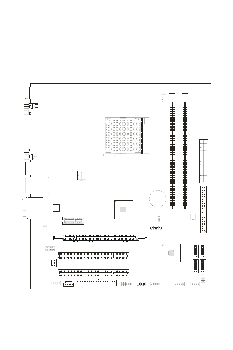
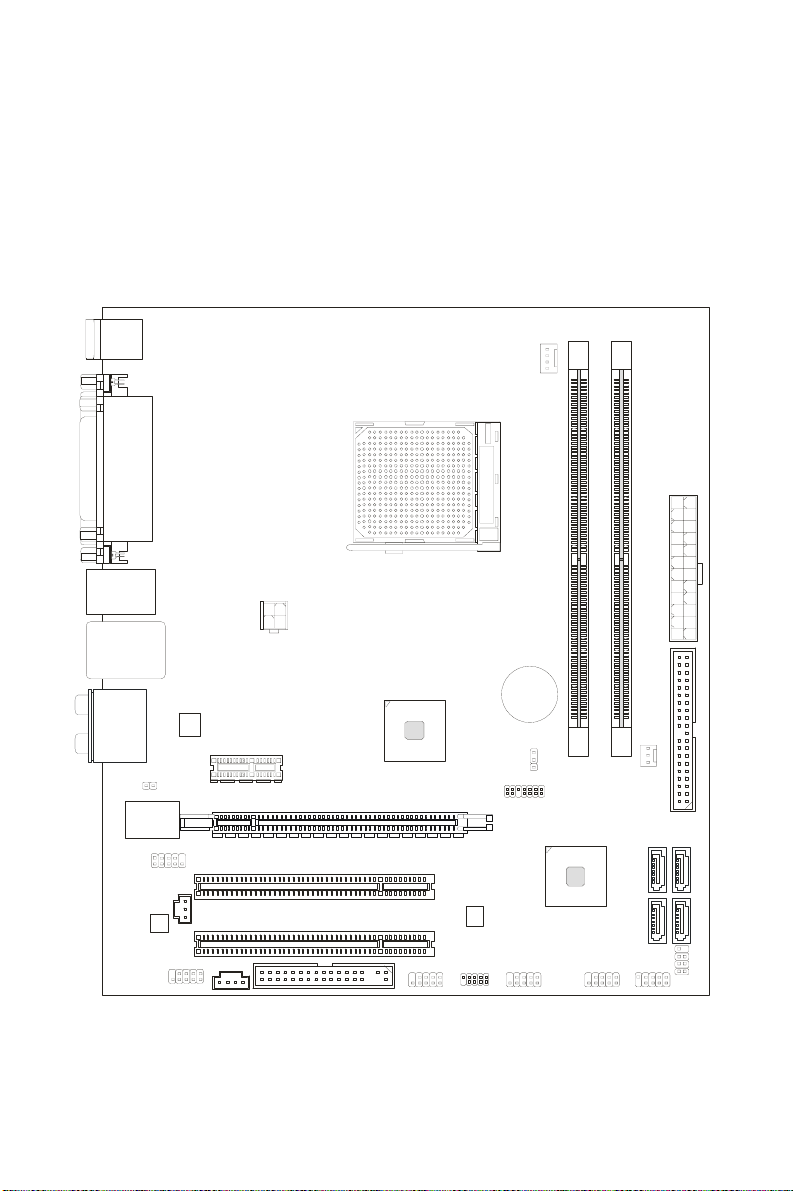
Layout
Top : mous e
Bottom:
keyboard
Top :
Parallel Port
Bottom:
COM portA
VGA port
Top:1394 (optional)
Bottom: USB ports
®
780G/740/780V + AMD®SB700 chipsets for optimal system efficiency.
®
Athlon 64 X2 / Athlon 64 / AM2+ processor, the
CPUFAN1
SOCKET AM2
DIMM1
DIMM2
ATX1
Top: LAN Jack
Bottom: USB ports
Line-In
T:
Line-Out
M:
Mic
B:
T:R S- O ut
M:CS-Out
B:SS-Out
1
JCI
JCOM2
JSP1
JAUD1
PCI 1
PCI 2
CD1
PWR1
PCIE1_X1
PCIE16_X 1
FDD 1
AMD
780G/
740/
780V
J1394_1
(optional)
BATT
+
JBAT1
JTPM1( optional)
AMD
SB700
SYSFAN1
SATA3
SATA1
JFP1JUSB1JUSB2JSPI1
IDE1
JFP2
SATA4
SATA2
Page 8

SPECIFICATIONS
Processor Support
z Supports AMD® Athlon64 / Athlon64 X2 /AM2+ processors
z Supports 4 pin CPU Fan Pin-Header with Fan Speed Control
z Supports up to 6000+ and higher CPU
(For the latest information about CPU, please visit
http://global.msi.com.tw/index.php?func=cpuform)
Supported FSB
z Hyper Transport support speed up to 3.0GHz
Chipset
z North Bridge: AMD® 780G/740/780V chipset (optional)
z South Bridge: AMD
Memory Support
z DDR2 533/667/800/1066 SDRAM (240pin / 1.8V)
z 2 DDR2 DIMMs (4GB Max)
(For more information on compatible components, please visit
http://global.msi.com.tw/index.php?func=testreport)
LAN
z Supports LAN 10/100/1000 Fast Ethermet by RTL8111C/8111B (optional)
z Supports LAN 10/100 Fast Ethermet by RTL8101E (optional)
IEEE1394 (optional)
z Chip integrated by JMicron 381
z Transfer rate is up to 400Mb/s
®
SB700 chipset
Audio
z Chip integrated by Realtek® ALC888 / ALC662 (optional)
z Flexible 8-channel audio with jack sensing
z Compliant with Azalia 1.0 Spec
IDE
z 1 IDE port by SB700
z Supports Ultra DMA 33/66/100/133 mode
z Supports PIO, Bus Master operation mode
SATA
z 4 SATA II ports by SB700
z Supports 4 SATA II devices
z Supports storage and data transfers at up to 300MB/s
RAID
z Supports RAID 0/ 1/ 0+1 or JBOD mode
2
Page 9

Floppy
z 1 floppy port
z Supports 1 FDD with 360KB, 720KB, 1.2MB, 1.44MB and 2.88MB
Connectors
z Back panel
- 1 PS/2 mouse port
- 1 PS/2 keyboard port
- 1 serial port (COM1)
- 1 VGA port
- 1 parallel port supporting SPP/EPP/ECP mode
- 1 IEEE 1394 port (optional)
- 4 USB 2.0 Ports
- 1 LAN jack
- 6 flexible audio jacks
z On-Board Pinheaders / Connectors
- 2 USB 2.0 pinheaders
- 1 COM port pinheader
- 1 CD-In connector
- 1 Front Panel Audio pinheader
- 1 SPDIF-Out pinheader
- 1 TPM pinheader (optional)
- 1 IEEE1394 pinheader (optional)
Slots
z 1 PCI Express x16 slot
z 1 PCI Express x1 slot
z 2 PCI slots
Form Factor
z M-ATX (24.4cm X 21.5cm)
Mounting
z 6 mounting holes
3
Page 10
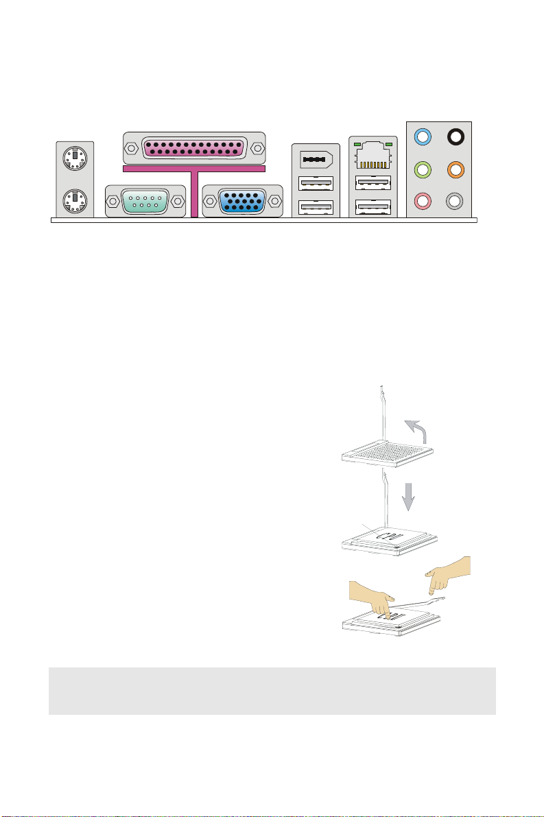
REAR PANEL
t
C
t
r
U
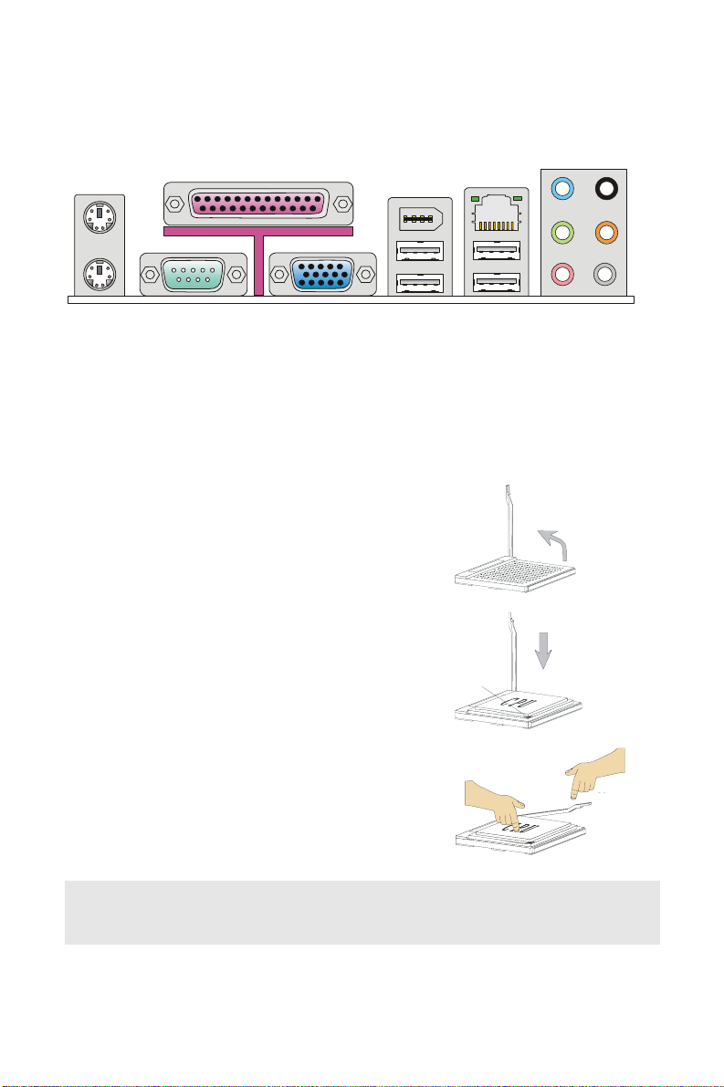
The rear panel provides the following connectors:
Parallel Port 1394 Port
Mouse
Line-In RS-Ou
LAN
(optional)
Keyboard Serial Port VGA Port
USB Ports
Line-Out
MI
CS-Ou
SS-Out
HARDWARE SETUP
This chapter tells you how to install the CPU, memory modules, and expansion cards, as
well as how to setup the jumpers on the mainboard. It also provides the instructions on
connecting the peripheral devices, such as the mouse, keyboard, etc. While doing the
installation, be careful in holding the components and follow the installation procedures.
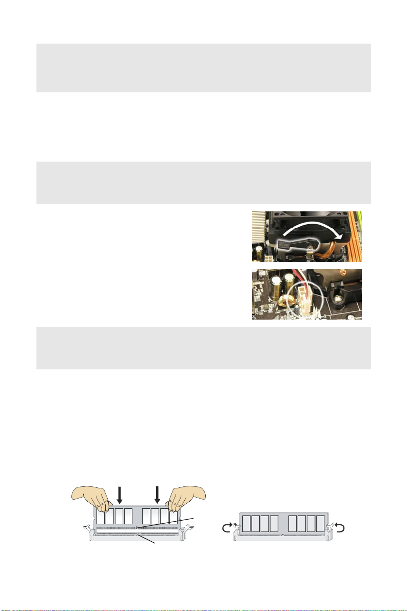
CPU Installation Procedures for Socket AM2
1. Please turn off the power and unplug the power
cord before installing the CPU.
2. Pull the lever sideways away from the socket.
Make sure to raise the lever up to a 90-degree
angle.
Sliding
the plate
3. Look for the gold arrow of the CPU. The gold
arrow should point as shown in the picture. The
CPU can only fit in the correct orientation.
4. If the CPU is correctly installed, the pins should be
completely embedded into the socket and can not
Gold arrow
be seen. Please note that any violation of the
correct installation procedures may cause
permanent damages to your mainboard.
Press down
the CPU
5. Press the CPU down firmly into the socket and
close the lever. As the CPU is likely to move while
the lever is being closed, always close the lever
with your fingers pressing tightly on top of the
CPU to make sure the CPU is properly and
completely embedded into the socket.
Important:
Overheating will seriously damage the CPU and system. Always make sure the cooling fan
can work properly to protect the CPU from overheating.
Open the leve
90 degree
Correct CP
placement
O
Close
the lever
4
Page 11
Make sure that you apply an even layer of heat sink paste (or thermal tape) between the
CPU and the heatsink to enhance heat dissipation.
While replacing the CPU, always turn off the ATX power supply or unplug the power supply
power cord from the grounded outlet first to ensure the safety of CPU.
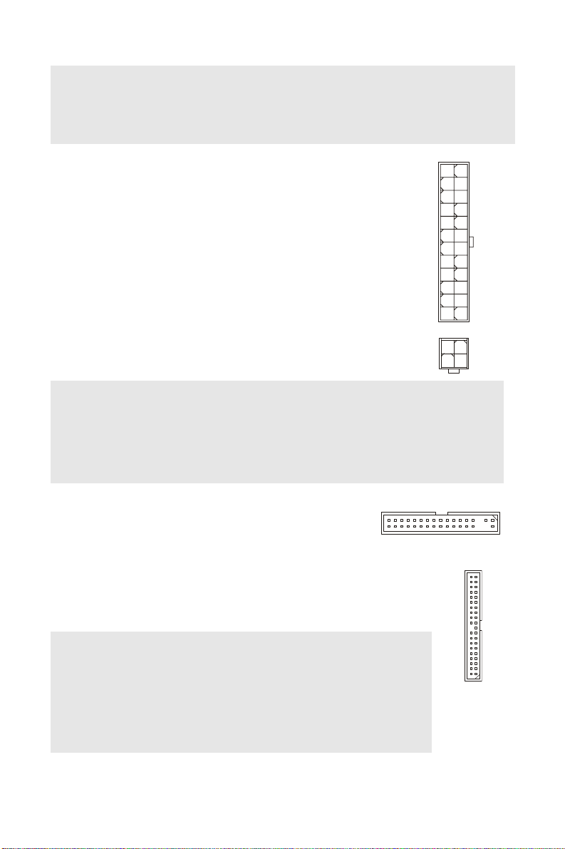
Installing AMD Socket AM2 CPU Cooler Set
When you are installing the CPU, make sure the CPU has a heat sink and a cooling fan
attached on the top to prevent overheating. If you do not have the heat sink and cooling fan,
contact your dealer to purchase and install them before turning on the computer.
Important:
Mainboard photos shown in this section are for demonstration of the cooler installation for
Socket AM2 CPUs only. The appearance of your mainboard may vary depending on the
model you purchase.
1. Position the cooling set onto the retention
mechanism. Hook one end of the clip to hook
first.
2. Then press down the other end of the clip to
fasten the cooling set on the top of the retention
mechanism. Locate the Fix Lever and lift up it.
3. Fasten down the lever.
4. Attach the CPU Fan cable to the CPU fan
connector on the mainboard.
Important:
While disconnecting the Safety Hook from the fixed bolt, it is necessary to keep an eye on
your fingers, because once the Safety Hook is disconnected from the fixed bolt, the fixed
lever will spring back instantly.
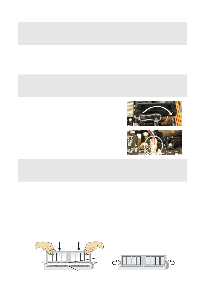
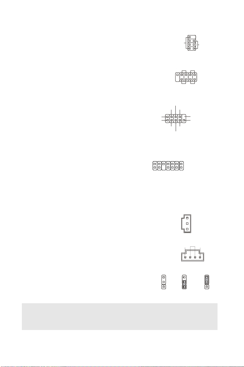
Installing Memory Modules
1. The memory module has only one notch on the center and will only fit in the right
orientation.
2. Insert the memory module vertically into the DIMM slot. Then push it in until the
golden finger on the memory module is deeply inserted in the DIMM slot. You can
barely see the golden finger if the memory module is properly inserted in the DIMM
slot.
3. The plastic clip at each side of the DIMM slot will automatically close.
Notch
Volt
5
Page 12
Important:
#
DDR2 memory modules are not interchangeable with DDR and the DDR2 standard is not
backwards compatible. You should always install DDR2 memory modules in the DDR2
DIMM slots.
To enable successful system boot-up, always insert the memory modules into the DIMM1
first.
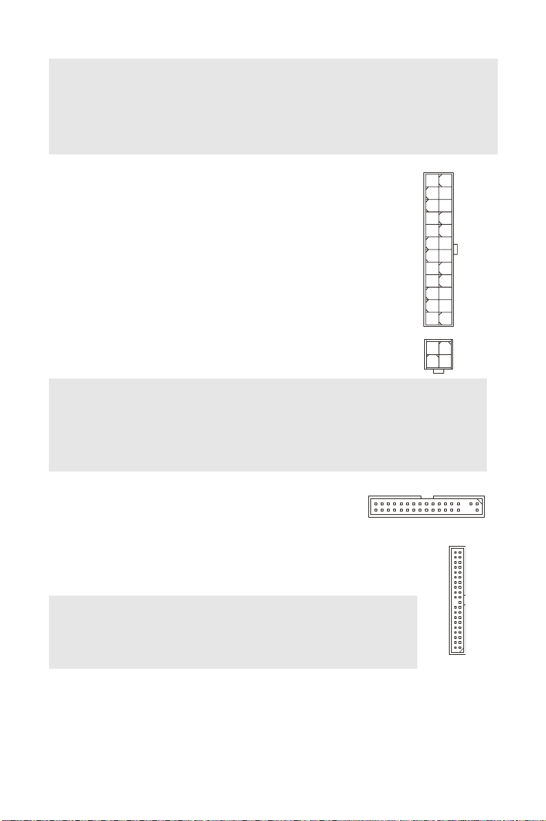
ATX 24-Pin Pow er Connector: ATX1
This connector allows you to connect an ATX 24-pin power supply.
To connect the ATX 24-pin power supply, make sure the plug of the
power supply is inserted in the proper orientation and the pins are
aligned. Then push down the power supply firmly into the
connector.
You may use the 20-pin ATX power supply as you like. If you like to
use the 20-pin ATX power supply, please plug your power supply
along with pin 1 & pin 13 (refer to the image at the right hand).
ATX 12V Power Connector: PWR1
This 12V power connector is used to provide power to the CPU.
+3.3V
+12V
+12V
5VSB
PWR OK
GND
+5V
GND
+5V
GND
+3.3V
+3.3V
GND
+5V
+5V
+5V
Res
GND
GND
GND
PS-ON
GND
-12V
+3.3V
GNDGND
+12V+12V
Important:
Make sure that all the connectors are connected to proper ATX power supplies to ensure
stable operation of the mainboard.
Power supply of 350 watts (and above) is highly recommended for system stability.
ATX 12V power connection should be greater than 18A.
Floppy Disk Drive Connector: FDD1
This connector supports 360KB, 720KB, 1.2MB, 1.44MB or
2.88MB floppy disk drive.
IDE Connector: IDE1
This connector supports IDE hard disk drives, optical disk drives and other
IDE devices.
Important:
If you install two IDE devices on the same cable, you must configure the
drives to cable select mode or separately to master / slave mode by setting
jumpers. Refer to IDE device documentation supplied by the vendors for
jumper setting instructions.
6
Page 13
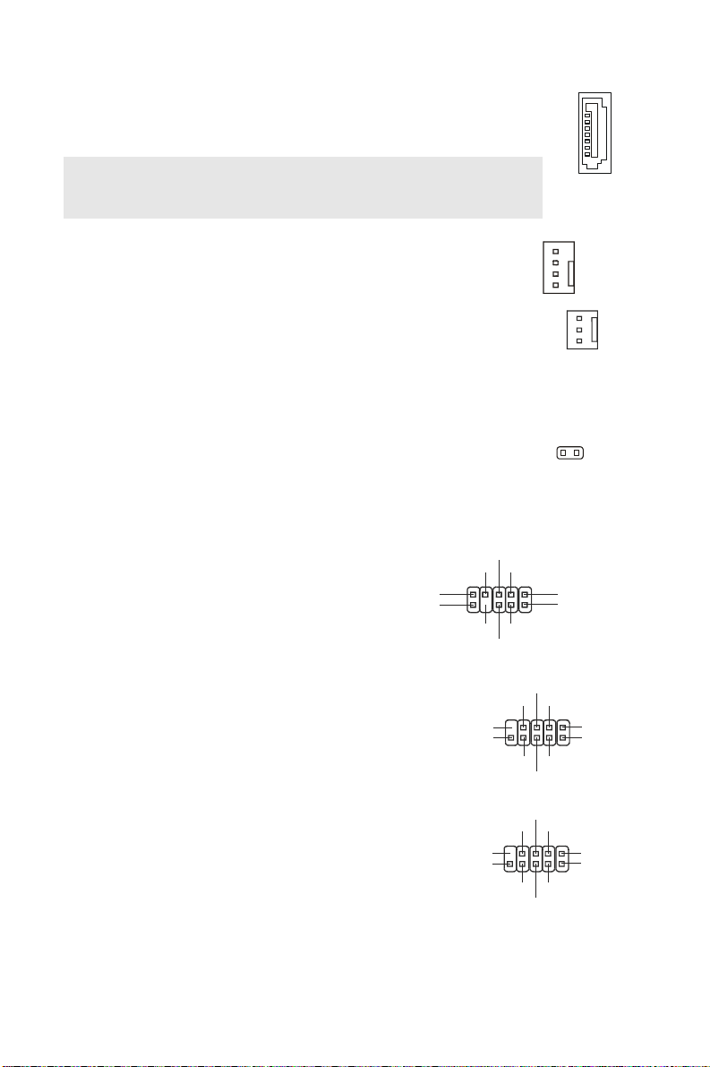
Serial ATA Connector: SATA1 ~ 4
U
US
TPB
This connector is a high-speed Serial ATA interface port. Each connector
can connect to one Serial ATA device.
Important:
Please do not fold the Serial ATA cable into 90-degree angle. Otherwise,
data loss may occur during transmission.
Fan Power Connectors: CPUFAN1,
SYSFAN1
The fan power connectors support system cooling fan with +12V.
When connecting the wire to the connectors, always note that the red
wire is the positive and should be connected to the +12V; the black
wire is Ground and should be connected to GND. If the mainboard
has a System Hardware Monitor chipset on-board, you must use a
specially designed fan with speed sensor to take advantage of the
CPU fan control.
Chassis Intrusion Connector: JCI
This connector connects to the chassis intrusion switch cable. If the
chassis is opened, the chassis intrusion mechanism will be activated.
The system will record this status and show a warning message on
the screen. To clear the warning, you must enter the BIOS utility and
clear the record.
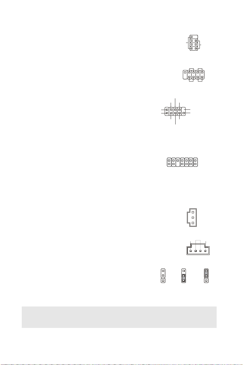
Front Panel Audio
Connector: JAUD1
This connector allows you to connect the
front panel audio and is compliant with
®
Intel
Front Panel I/O Connectivity Design
Guide.
Front to Sense
(9)Line-out_L
(10)Line_JD
Line-out_R
NC
MIC2_JD
Front USB Connector: JUSB1/2
This connector, compliant with Intel® I/O
Connectivity Design Guide, is ideal for connecting
high-speed USB interface peripherals such as USB
HDD, digital cameras, MP3 players, printers,
modems and the like.
IEEE1394 Connector:
J1394_1(optional)
This connector allows you to connect the IEEE1394
device via an optional IEEE1394 bracket.
(9)Key,no pin
(10)N.C.
Cable power
(9)Key,no pin
(10)GND
Cable power
MIC_R
VCC5
USB0+
GND
GND
TPB-
Sensor
+12V
GND
GND
USB0-
USB1-
B1+
+
GND
GND
Control
Sensor
+12V
GND
21
CINTR
MIC_L(1)
GND(2)
VCC(1)
VCC(2)
TPA+(1)
TPA-(2)
7
Page 14
Front Panel Connectors: JFP1,
HDD
R
S
S
G
G
JFP2
These connectors are for electrical connection to the
front panel switches and LEDs. The JFP1 is compliant
with Intel
®
Front Panel I/O Connectivity Design Guide.
Serial Port Connector: JCOM2
This connector is a 16550A high speed communication
port that sends/receives 16 bytes FIFOs. You can
attach a serial device.
TPM Module connector:
JTPM1(optional)
This connector connects to a TPM (Trusted Platform
Module) module. Please refer to the TPM security
platform manual for more details and usages.
(1)
(2)
JFP2
JFP1
SIN
DCD
DTR
SOUT
13
14
D
#
E
M
A
R
F
L
D
N
G
8
Speaker
2
eset
Switch
+---
10 2
Power
witch
R
CTS
Key,no pin
RI
RTS
ND
0
1
2
3
D
D
D
D
A
A
A
A
L
L
L
L
5
Y
D
Q
C
E
N
R
I
C
K
G
S
V
+
#
T
S
R
L
3
C
C
V
7
1
LED
Power
LED
(9)
K
L
C
L
1
2
B
T
S
_
V
3
/
l
a
u
d
V
3
Power
+
LED
19
(10)
S/PDIF-Out Connector: JSP1
This connector is used to connect S/PDIF (Sony & Philips Digital
Interconnect Format) interface for digital audio transmission.
CD-In Connector: CD1
GND
SPDIF
VCC
ND
LR
This connector is provided for external audio input.
Clear CMOS Jumper: JBAT1
There is a CMOS RAM onboard that has a power supply
from an external battery to keep the data of system
configuration. With the CMOS RAM, the system can
automatically boot OS every time it is turned on. If you want
3
2
1
Keep Dat a Clear Data
33
22
11
to clear the system configuration, set the jumper to clear
data.
Important:
You can clear CMOS by shorting 2-3 pin while the system is off. Then return to 1-2 pin
position. Avoid clearing the CMOS while the system is on; it will damage the mainboard.
8
Page 15
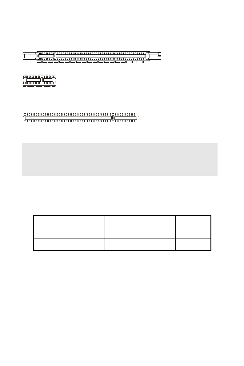
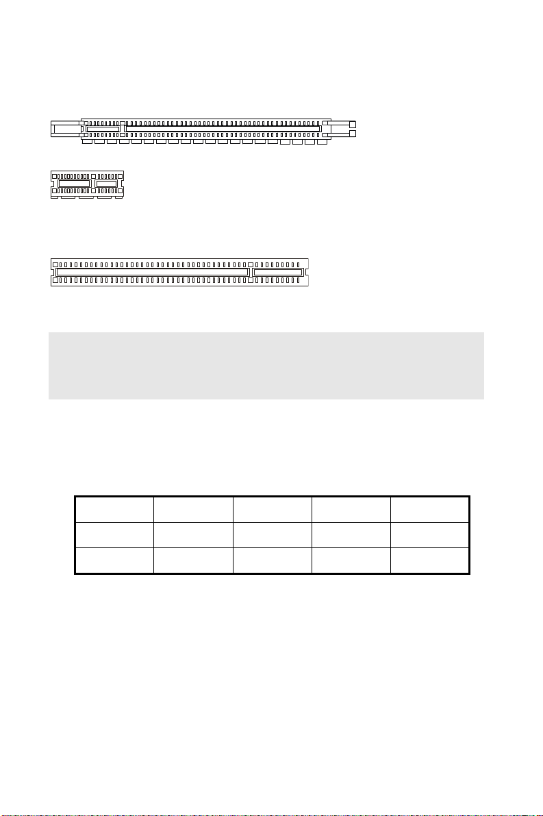
PCI (Peripheral Component Interconnect) Express Slot
The PCI Express slot supports the PCI Express interface expansion card.
The PCI Express x 16 slot supports up to 4.0 GB/s transfer rate.
The PCI Express x 1 slot supports up to 250 MB/s transfer rate.
PCI (Peripheral Component Interconnect) Slot
The PCI slot supports LAN card, SCSI card, USB card, and other add-on cards that
comply with PCI specifications.
Important:
When adding or removing expansion cards, make sure that you unplug the power supply
first. Meanwhile, read the documentation for the expansion card to configure any
necessary hardware or software settings for the expansion card, such as jumpers,
switches or BIOS configuration.
PCI Interrupt Request Routing
The IRQ, acronym of interrupt request line and pronounced I-R-Q, are hardware lines over
which devices can send interrupt signals to the microprocessor. The PCI IRQ pins are
typically connected to the PCI bus pins as follows:
Order1 Order2 Order3 Order4
PCI Slot1 INT A# INT B# INT C# INT D#
PCI Slot2 INT B# INT C# INT D# INT A#
9
Page 16
BIOS Setup
Power on the computer and the system will start POST (Power On Self Test) process. When
the message below appears on the screen, press <DEL> key to enter Setup.
Press DEL to enter SETUP
If the message disappears before you respond and you still wish to enter Setup, restart the
system by turning it OFF and On or pressing the RESET button. You may also restart the
system by simultaneously pressing <Ctrl>, <Alt>, and <Delete> keys.
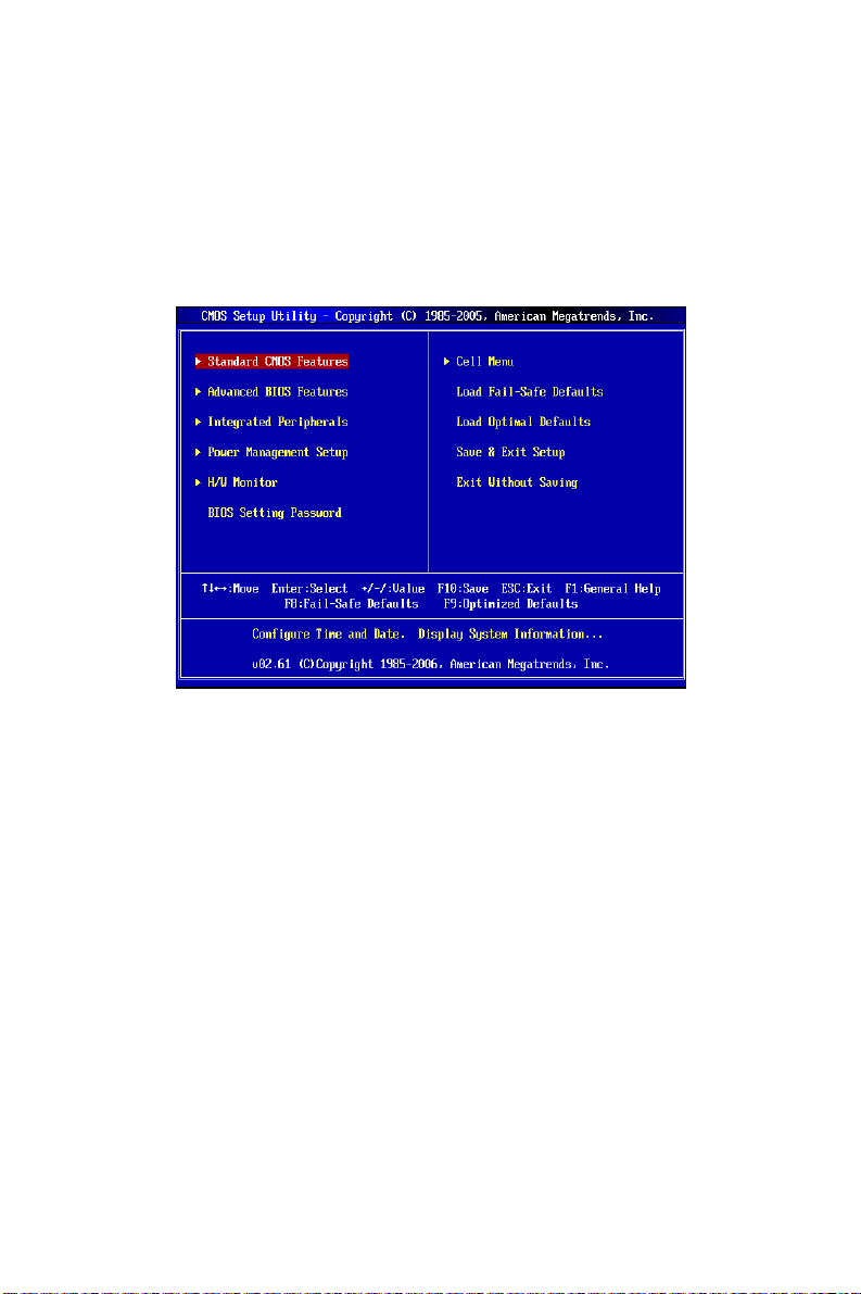
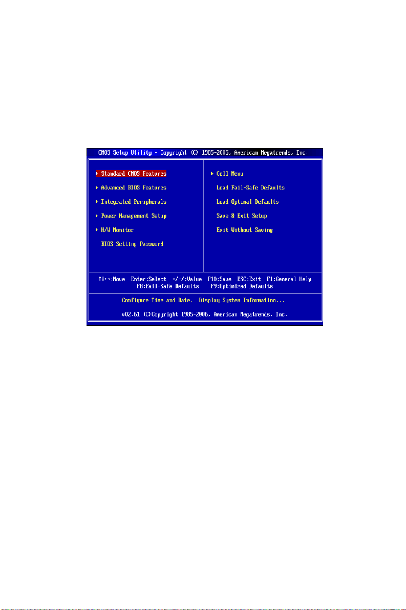
Main Page
Standard CMOS Features
Use this menu for basic system configurations, such as time, date etc.
Advanced BIOS Features
Use this menu to setup the items of special enhanced features.
Integrated Peripherals
Use this menu to specify your settings for integrated peripherals.
Power Management Setup
Use this menu to specify your settings for power management.
H/W Monitor
This entry shows the status of your CPU, fan, warning for overall system status.
BIOS Setting Password
Use this menu to set BIOS setting Password.
Cell Menu
Use this menu to specify your settings for frequency/voltage control.
Load Fail-Safe Defaults
Use this menu to load the default values set by the BIOS vendor for stable system
performance.
10
Page 17
Load Optimized Defaults
Use this menu to load the default values set by the mainboard manufacturer specifically for
optimal performance of the mainboard.
Save & Exit Setup
Save changes to CMOS and exit setup.
Exit Without Saving
Abandon all changes and exit setup.
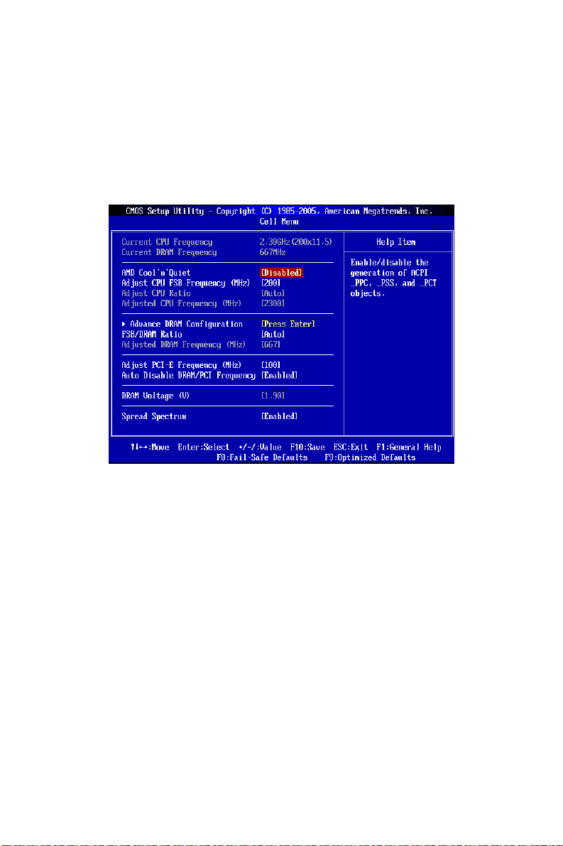
Cell Menu
Current CPU/DRAM Frequency
These items show the current clocks of CPU and Memory speed. Read-only.
AMD Cool’n’Quiet
This feature is especially designed for AMD processor, which provides a CPU temperature
detecting function to prevent your CPU from overheating due to the heavy working loading.
Adjust CPU FSB Frequency (MHz)
This item allows you to set the CPU FSB frequency (in MHz).
Adjust CPU Ratio
This item allows you to set the CPU frequency multiplier (ratio).
Adjusted CPU Frequency (MHz)
It shows the adjusted CPU frequency. Read-only.
Advance DRAM Configuration
Press <Enter> to enter the sub-menu.
Advance DRAM Configuration -> DRAM Timing Mode
Setting to [Auto] enables DRAM CAS# Latency automatically to be determined by BIOS
based on the configurations on the SPD (Serial Presence Detect) EEPROM on the DRAM
module.
11
Page 18

Advance DRAM Configuration -> CAS Latency (CL)
When the DRAM Timing sets to [Manual], the field is adjustable.This controls the CAS
latency, which determines the timing delay (in clock cycles) before SDRAM starts a read
command after receiving it.
Advance DRAM Configuration -> TRCD
When the DRAM Timing sets to [Manual], the field is adjustable. When DRAM is refreshed,
both rows and columns are addressed separately. This setup item allows you to determine
the timing of the transition from RAS (row address strobe) to CAS (column address strobe).
The less the clock cycles, the faster the DRAM performance.
Advance DRAM Configuration -> TRP
When the DRAM Timing sets to [Manual], this field is adjustable. This setting controls the
number of cycles for Row Address Strobe (RAS) to be allowed to precharge. If insufficient
time is allowed for the RAS to accumulate its charge before DRAM refresh, refresh may be
incomplete and DRAM may fail to retain data. This item applies only when synchronous
DRAM is installed in the system.
Advance DRAM Configuration -> TRAS
When the DRAM Timing sets to [Manual], this setting determines the time RAS takes to
read from and write to a memory cell.
Advance DRAM Configuration -> TRTP
When the DRAM Timing sets to [Manual], this setting controls the time interval between a
read and a precharge command.
Advance DRAM Configuration -> TRC
When the DRAM Timing sets to [Manual], the field is adjustable. The row cycle time
determines the minimum number of clock cycles a memory row takes to complete a full
cycle, from row activation up to the precharging of the active row.
Advance DRAM Configuration -> TWR
When the DRAM Timing sets to [Manual], the field is adjustable. It specifies the amount of
delay (in clock cycles) that must elapse after the completion of a valid write operation,
before an active bank can be precharged. This delay is required to guarantee that data in
the write buffers can be written to the memory cells before precharge occurs.
Advance DRAM Configuration -> TRRD
When the DRAM Timing sets to [Manual], the field is adjustable. Specifies the
active-to-active delay of different banks.
Advance DRAM Configuration -> TWTR
When the DRAM Timing sets to [Manual], the field is adjustable. This item controls the Write
Data In to Read Command Delay memory timing. This constitutes the minimum number of
clock cycles that must occur between the last valid write operation and the next read
command to the same internal bank of the DDR device.
Advance DRAM Configuration -> 1T/2T Memory Timing
When the DRAM Timing sets to [Manual], the field is adjustable. This field controls the
SDRAM command rate. Selecting [1T] makes SDRAM signal controller to run at 1T
(T=clock cycles) rate. Selecting [2T] makes SDRAM signal controller run at 2T rate.
Advance DRAM Configuration -> SoftWare Memory Hole
When the DRAM Timing sets to [Manual], the field is adjustable. This field allows you to
enable or disable SoftWare Memory Hole.
12
Page 19

FSB/DRAM Ratio
This item allows you to set the FSB/DRAM ratio.
Adjusted DRAM Frequency (MHz)
It shows the adjusted DDR memory frequency. Read-only.
Adjust PCI-E Frequency (MHz)
This item allows you to set the PCI-E frequency (in MHz).
Auto Disable DRAM/PCI Frequency
This item is used to auto detect the DIMM/PCI slots. When set to [Enabled], the system will
remove (turn off) clocks from empty DIMM/PCI slots to minimize the electromagnetic
interference (EMI).
DRAM Voltage (V)
This item will allow you to adjust the Memory voltage.
Spread Spectrum
When the motherboard’s clock generator pulses, the extreme values (spikes) of the pulses
create EMI (Electromagnetic Interference). The Spread Spectrum function reduces the EMI
generated by modulating the pulses so that the spikes of the pulses are reduced to flatter
curves. If you do not have any EMI problem, leave the setting at Disabled for optimal system
stability and performance. But if you are plagued by EMI, set to Enabled for EMI reduction.
Remember to disable Spread Spectrum if you are overclocking because even a slight jitter
can introduce a temporary boost in clock speed which may just cause your overclocked
processor to lock up.
Important:
If you do not have any EMI problem, leave the setting at [Disabled] for optimal system
stability and performance. But if you are plagued by EMI, select the value of Spread
Spectrum for EMI reduction.
The greater the Spread Spectrum value is, the greater the EMI is reduced, and the system
will become less stable. For the most suitable Spread Spectrum value, please consult your
local EMI regulation.
Remember to disable Spread Spectrum if you are overclocking because even a slight jitter
can introduce a temporary boost in clock speed which may just cause your overclocked
processor to lock up.
13
Page 20
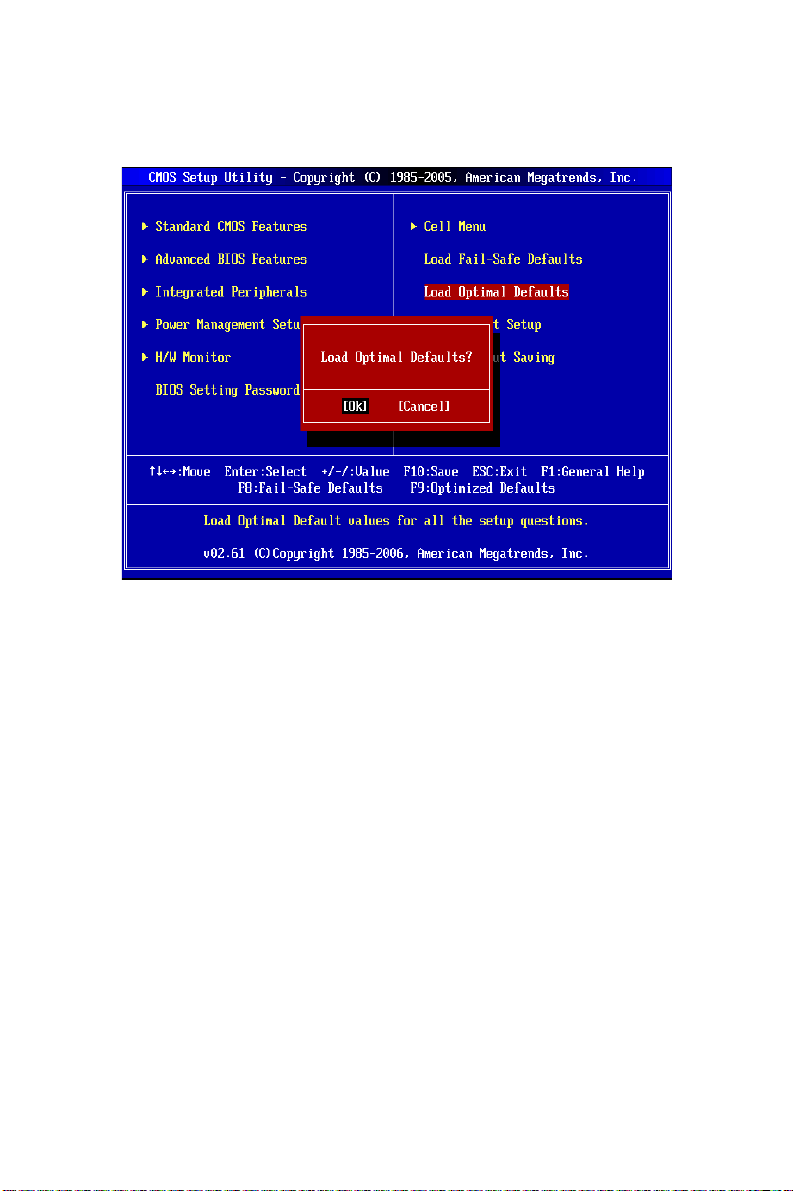
Load Optimized Defaults
You can load the default values provided by the mainboard manufacturer for the stable
performance.
14
Page 21
소개
K9A2GM V2 / K9A2GM V3 / K9A2VM V2 시리즈 (MS-7302 v1.x) Micro-ATX 메인보드를
선택해주셔서 감사합니다. K9A2GM V2 / K9A2GM V3 / K9A2VM V2 시리즈는 최적의
시스템 효율을 위해 AMD
고급의 AMD
®
Athlon 64 X2 / Athlon 64 / AM2+ 프로세서에 적합하게 디자인된 K9A2GM
V2 / K9A2GM V3 / K9A2VM V2 시리즈는 고성능과 전문적인 데스크톱 플랫폼 솔루션을
제공합니다.
레이아웃
Top : mouse
Bottom:
keyboa rd
Top :
Parallel Port
Bottom:
COM portA
VGA port
Top:1394(opt i onal)
Bottom: USB ports
®
780G/740/780V + AMD®SB700 칩셋에 기반을 둔 제품입니다.
CPUFAN1
SOCKET AM2
ATX1
DIMM1
DIMM2
Top: LAN Jack
Bottom: USB ports
T:
Line-In
M:
Line-Out
B:
Mic
T:RS-Out
M:CS-Out
B:SS-Out
15
JCI
JCOM2
JSP1
PCIE1_X1
PCIE16_X1
PCI 1
PCI 2
CD1JAUD1
PWR1
FDD 1
AMD
780G/
740/
780V
J1394_1
(optional)
BATT
+
JBAT1
JTPM1(optional)
AMD
SB700
SYSFAN1
SATA3
SATA1
JFP1JUSB1JUSB2J SPI 1
IDE1
JFP2
SATA4
SATA2
Page 22

사양
지원되는 프로세서
®
z AMD
z 팬 속도 컨트롤이 있는 4 핀 CPU 팬 핀헤더 지원
z 최대 6000+ 이상 CPU 지원
지원되는 FSB
z 하이퍼 전송 지원 최대 속도 3.0GHz
칩셋
z 노스 브릿지: AMD® 780G/740/780V 칩셋(옵션)
z 사우스 브릿지: AMD® SB700 칩셋
지원되는 메모리
z DDR2 533/667/800/1066 SDRAM (240 핀 / 1.8V)
z 2 DDR2 DIMMs (4GB Max)
(호환 가능한 부품에 대한 자세한 내용은
http://global.msi.com.tw/index.php?func=testreport를 참조하십시오.)
LAN
z RTL8111C/8111B 에 의해 LAN 10/100/1000 고속 이더넷 지원(옵션)
z RTL8101E 에 의해 LAN 10/100 고속 이더넷 지원(옵션)
IEEE1394(옵션)
z JMicron 381 에 의해 통합된 칩
z 400Mb/s 의 최대 전송 속도
Athlon64 / Athlon64 X2 /AM2+ 프로세서 지원
(CPU 에 대한 최신 정보는
http://global.msi.com.tw/index.php?func=cpuform 참조)
오디오
z Realtek® ALC888 / ALC662 에 의해 통합된 칩(옵션)
z 잭 감지 기능이 있는 플렉시블 8 채널 오디오
z Azalia 1.0 규격 준수
IDE
z SB700 에 의한 IDE 포트 1 개
z Ultra DMA 33/66/100/133 모드 지원
z PIO, 버스 마스터 작동 모드 지원
SATA
z SB700 SATA II 포트 4 개
z 4 개의 SATA II 장치 지원
z 최대 300 MB/s 의 저장 및 데이터 전송 지원
RAID
z RAID 0/1/0+1 또는 JBOD 모드 지원(ICH7R 에만 해당)
16
Page 23

플로피
z 플로피 포트 1 개
z 360KB, 720KB, 1.2MB, 1.44MB 및 2.88MB 의 FDD 1 개 지원
커넥터
z 후면 패널
- PS/2 마우스 포트 1 개
- PS/2 키보드 포트 1 개
- 직렬 포트(COM1) 1 개
- VGA 포트 1 개
- SPP/EPP/ECP 모드를 지원하는 병렬 포트 1 개
- IEEE 1394 포트 1 개(옵션)
- USB 2.0 포트 4 개
- LAN 잭 1 개
- 플렉시블 오디오 잭 6 개
z 온보드 핀헤더/커넥터
- USB 2.0 핀헤더 2 개
- COM 포트 핀헤더 l 개
- CD 입력 커넥터 1 개
- 전면 패널 오디오 핀헤더 1 개
- SPDIF 출력 핀헤더 1 개
- TPM 핀헤더 1 개(옵션)
- IEEE 1394 핀헤더 1 개(옵션)
슬롯
z PCI Express x16 슬롯 1 개
z PCI Express x1 슬롯 1 개
z PCI 슬롯 2 개
폼 팩터
z M-ATX(24.4cm X 21.5cm)
장착
z 장착 구멍 6 개
17
Page 24
뒷면
t
C
t
r
U
r
뒷면에는 다음 커넥터가 있습니다.
Parallel Port 1394 Port
Mouse
마우스
병렬 포트
1394
(optional)
포트(옵션)
Line-In RS-Ou
라인 입력 RS 출력
LAN
LAN
Keyboard Serial Port VGA Port
키보드 직렬 포트 VGA 포트
USB Ports
USB 포트
Line-Out
라인 출력 CS 출력
MI
마이크 SS 출력
CS-Ou
SS-Out
하드웨어 설치
이 장에서는 CPU, 메모리 모듈, 확장 카드의 설치 방법과 메인보드의 점퍼 설정
방법을 설명합니다. 또한 마우스, 키보드 등과 같은 주변 장치의 연결 방법을
설명합니다. 설치하는 동안, 부품을 주의해서 취급하고 설치 절차를 잘 따르십시오.
소켓 AM2/ AM2 용 CPU 설치 절차
1. CPU 를 설치하기 전에 전원을 끄고 전원 코드를
뽑습니다.
2. 레버를 소켓에서 비스듬히 당깁니다. 레버를
90 도까지 올립니다.
플레이트
Sliding
밀기
the plate
3. CPU 의 금색 화살표를 찾습니다. 금색 화살표가
그림과 같이 가리키고 있어야 합니다. CPU 는
올바른 한 쪽 방향으로만 끼워집니다.
4. CPU 가 올바로 설치되면, 핀이 소켓에 완전히
끼워져서 보이지 않게 됩니다. 올바른 설치
절차를 따르지 않으면 메인보드가 영구적으로
금색
화살표
Gold arrow
손상될 수 있습니다.
5. CPU 를 소켓 안으로 꽉 눌러 넣고 레버를
닫습니다. 레버를 닫는 동안 CPU 가 움직일
우려가 있기 때문에, 레버를 닫을 때는 항상
CPU 를 아래로
Press down
the CPU
누릅니다.
손가락으로 CPU 의 상단을 꽉 눌러 CPU 가
소켓 안에 제대로 완전히 끼워지도록 해야
합니다.
중요:
과열은 CPU 와 시스템을 심각하게 손상시킬 수 있습니다. CPU 가 과열되지 않도록
냉각 팬이 제대로 작동하는지 항상 확인하십시오.
레버를 엽니다.
Open the leve
90 도
90 degree
CPU 위치를
Correct CP
수정합니다.
placement
O
Close
레버를
the leve
닫습니다.
18
Page 25
열이 잘 발산되도록 CPU 와 방열판 사이에 방열판용 페이스트(또는 서멀 테이프)를
고르게 바르십시오.
CPU 교체 시, 항상 ATX 전원을 끄거나 먼저 전원 공급장치의 전원 코드를 접지된
콘센트에서 뽑아 CPU 의 안전을 확보하십시오.
AMD 소켓 AM2 CPU 쿨러 세트 설치
CPU 설치 시 과열을 방지하는 방열판과 냉각 팬을 상단에 연결하십시오. 방열판과
냉각 팬이 없는 경우, 컴퓨터를 켜기 전에 판매점에 문의하여 방열판과 냉각 팬을
설치하십시오.
중요:
이 절에 표시된 메인보드 사진은 Socket AM2 CPU 용 쿨러 설치를 보여줄 목적으로만
사용된 사진입니다. 메인보드의 외양은 구입한 모델에 따라 다를 수 있습니다.
1. 쿨러 세트를 고정 위치에 올려놓습니다. 먼저
클립의 한쪽 끝을 사용하여 겁니다.
2. 그리고 나서 클립의 다른 쪽 끝을 눌러 쿨러
세트를 고정 위치의 상단에 고정합니다. 고정
레버를 찾아 위로 올립니다.
3. 레버를 아래로 눌러 고정합니다.
4. CPU 팬 케이블을 메인보드의 CPU 팬
커넥터에 연결합니다.
중요:
안전 훅이 고정 볼트에서 분리되는 즉시 고정 레버가 다시 튀어 오르기 때문에, 고정
볼트에서 안전 훅을 분리할 때는 손가락에서 눈을 떼지 마십시오.
메모리 모듈 설치
1. 메모리 모듈은 중앙에 노치가 하나만 있으며, 오른쪽 방향으로만 맞습니다.
2. 메모리 모듈을 DIMM 슬롯에 수직으로 끼웁니다. 그리고 나서 메모리 모듈 위의
골든 핑거가 DIMM 슬롯에 깊이 삽입될 때까지 밀어 넣습니다. 메모리 모듈이
DIMM 슬롯에 제대로 삽입되면 골든 핑거가 거의 보이지 않습니다.
3. DIMM 슬롯의 양쪽에 있는 플라스틱 클립이 자동으로 닫힙니다.
Notch
노치
Volt
볼트
19
Page 26
중요:
#
DDR2 메모리 모듈은 DDR 과 서로 교환되지 않으며, DDR2 표준은 역호환이 되지
않습니다. 항상 DDR2 DIMM 슬롯에 DDR2 메모리 모듈을 설치해야 합니다.
성공적인 시스템 부팅을 하려면, 먼저 메모리 모듈을 DIMM 에 끼우십시오.
ATX 24 핀 전원 커넥터: ATX1
이 커넥터를 사용하여 ATX 24 핀 전원 공급장치를 연결할 수
있습니다. ATX 24 핀 전원 공급장치를 연결하려렴, 전원
공급장치의 플러그가 올바른 방향으로 삽입되었는지, 핀이
정렬되었는지 확인하십시오. 그리고 나서 전원 공급장치를
커넥터 안쪽으로 꽉 맞게 누릅니다.
원하는 경우 20 핀 ATX 전원 공급장치를 사용할 수 있습니다.
20 핀 ATX 전원 공급장치를 사용하려면, 전원 공급장치의
플러그를 핀 1 및 핀 13 과 함께 연결하십시오(오른쪽 이미지
참조).
ATX 12V 전원 커넥터: PWR1
12V 전원 커넥터는 CPU 에 전원을 공급하는 데 사용됩니다.
+3.3V
+12V
+12V
5VSB
PWR OK
GND
+5V
GND
+5V
GND
+3.3V
+3.3V
GND
+5V
+5V
+5V
Res
GND
GND
GND
PS-ON
GND
-12V
+3.3V
GNDGND
+12V+12V
중요:
모든 커넥터가 올바른 ATX 전원 공급장치에 연결되어 메인보드의 작동이 안정적인지
확인하십시오.
시스템 안정성을 위해 350 와트 이상의 전원 공급장치를 권장합니다.
ATX 12V 전원 연결은 18A 보다 커야 합니다.
플로피 디스크 장치 커넥터: FDD1
이 커넥터는 360KB, 720KB, 1.2MB, 1.44MB 또는 2.88MB
플로피 디스크 드라이브를 지원합니다.
IDE 커넥터: IDE1
이 커넥터는 IDE 하드 디스크 드라이브, 광학 디스크 드라이브 및 기타
IDE 장치를 지원합니다.
중요:
동일한 케이블에 2 개의 IDE 장치를 설치하는 경우, 점퍼 설정으로
드라이브를 케이블 선택 모드로, 또는 마스터/슬레이브에 별도로
구성해야 합니다. 점퍼 설정 방법은 공급업체가 제공한 IDE 장치의
설명서를 참조하십시오.
20
Page 27

직렬 ATA 커넥터: SATA1 ~ 4
r
U
2
1
US
이 커넥터는 고속의 직렬 ATA 인터페이스 포트에 사용됩니다. 각
커넥터는 하나의 직렬 ATA 장치에 연결할 수 있습니다.
중요:
직렬 ATA 케이블을 90 도로 꺾지 마십시오. 그럴 경우, 전송 중
데이터가 손실될 수 있습니다.
팬 전원 커넥터: CPUFAN1, SYSFAN1
팬 전원 커넥터는 +12V 의 시스템 냉각 팬을 지원합니다. 전선을
커넥터에 연결할 때, 항상 빨간색 전선이 양극으로서 +12V 에
연결되어야 하고, 검은색 전선은 접지선으로서 GND 에 연결되어야
합니다. 메인보드에 시스템 하드웨어 모니터 칩셋 온보드가 있는
경우, CPU 팬 제어를 활용하기 위해 속도 센서가 있는 특별히
디자인된 팬을 사용해야 합니다.
섀시 침입 커넥터: JCI
이 커넥터는 섀시 침입 스위치 케이블에 연결됩니다. 섀시가
열리는 경우, 섀시 침입 메커니즘이 활성화됩니다. 시스템이 이
상태를 기록하고 화면에 경고 메시지를 표시합니다. 경고를
지우려면, BIOS 유틸리티에서 레코드를 지워야 합니다.
센서
Sensor
+12V
GND
GND
컨트롤
Control
센서
Senso
+12V
GND
CINTR
전면 패널 오디오 커넥터:
JAUD1
이 커넥터를 사용하여 전면 패널 오디오를
연결할 수 있으며, 이 커넥터는 Intel® Front
Panel I/O Connectivity Design Guide 를
준수합니다.
(9)Line-out_L
전면 USB 커넥터: JUSB1/2
Intel® I/O Connectivity Design Guide 를 준수한
이 커넥터는 USB HDD, 디지털 카메라, MP3
플레이어, 프린터, 모뎀 등과 같은 고속의 USB
인터페이스 주변 장치를 연결하는 데 적합합니다.
IEEE1394 커넥터: J1394_1(옵션)
이 커넥터를 사용하여 옵션인 IEEE1394 브래킷을
통해 IEEE1394 장치를 연결할 수 있습니다.
21
앞면 감지
Front to Sense
(10)Line_JD
(9)키, 핀 없음
(9)Key,no pin
(10)N.C.
(9)키, 핀 없음
(9)Key,no pin
(10)GND
Line-out_R
NC
MIC2_JD
GND
GND
케이블 전원
Cable power
Cable power
케이블 전원
MIC_R
VCC5
USB0+
B1+
TPB+
TPB-
USB0-
USB1-
GND
GND
MIC_L(1)
GND(2)
VCC(1)
VCC(2)
TPA+(1)
TPA-(2)
Page 28
전면 패널 커넥터: JFP1, JFP2
S
G
)
2
G
a
이 커넥터는 전면 패널 스위치 및 LED에 대한 전기
연결에 사용됩니다. JFP1 은 Intel
Connectivity Design Guide를 준수합니다.
®
Front Panel I/O
직렬 포트 커넥터: JCOM2
이 커넥터는 16550A 고속 통신 포트로서 16
바이트의 FIFO 를 송수신합니다. 직렬 장치를
연결할 수 있습니다.
TPM 모듈 커넥터: JTPM1(옵션)
이 커넥터는 TPM(Trusted Platform Module) 모듈에
연결됩니다. 자세한 내용과 사용법은 TPM 보안
플랫폼 설명서를 참조하십시오.
(2)
(1)
13
14
JFP2
JFP1
SIN
DCD
#
E
M
A
R
F
L
D
N
G
Speaker
스피커
10 2
Power
전원 스위치
전원 LED
DSR
DTR
SOUT
ND
0
1
2
3
D
D
D
D
A
A
A
A
L
L
L
L
5
Y
D
Q
키
C
E
N
R
I
C
K
G
S
V
8
2
HDD
Reset
HDD 리셋
스위치 LED
LED
Switch
+---
+
Power
witch
LED
CTS
키, 핀 없음(10)
Key,no pin
RI
RTS
#
T
K
L
S
C
R
L
L
1
3
B
T
C
S
C
_
V
V
3
/
l
a
u
d
V
3
7
1
+
(9)
Power
전원 LED
LED
19
(10
S/PDIF 출력 커넥터: JSP1
이 커넥터는 디지털 오디오 전송을 위해 S/PDIF(Sony & Philips
Digital Interconnect Format) 인터페이스를 연결하는 데
사용됩니다.
CD 입력 커넥터: CD1
GND
SPDIF
VCC
ND
LR
이 커넥터는 외부 오디오 입력용으로 제공됩니다.
CMOS 점퍼 지우기: JBAT1
보드에 시스템 구성 데이터를 유지하기 위해 외부
배터리로부터 전원을 공급 받은 CMOS RAM 이 있습니다.
CMOS RAM의 경우, 시스템을 켤 때마다 시스템이 OS 를
자동으로 부팅합니다. 시스템 구성을 지우려면, 점퍼를
설정하여 데이터를 지우십시오.
중요:
시스템이 꺼져 있는 동안 2-3 핀을 단락시켜 CMOS 를 지울 수 있습니다. 그리고
나서 1-2 핀 위치로 돌아가십시오. 시스템이 켜 있는 동안에는 CMOS 를 지우지
마십시오. 그럴 경우 메인보드가 손상될 수 있습니다.
22
3
2
1
Keep Data Clear Dat
데이터 보관
33
22
11
데이터 지우기
Page 29
PCI(Peripheral Component Interconnect) Express 슬롯
PCI Express 슬롯은 PCI Express 인터페이스 확장 카드를 지원합니다.
PCI Express x 16 슬롯은 최대 4.0 GB/s 의 전송률을 지원합니다.
PCI Express x 1 슬롯은 최대 250 MB/s 의 전송률을 지원합니다.
PCI(Peripheral Component Interconnect) 슬롯
PCI 슬롯은 LAN 카드, SCSI 카드, USB 카드 및 PCI 규격을 준수하는 기타 애드온
카드를 지원합니다.
중요:
확장 카드를 추가하거나 제거할 때 먼저 전원 공급장치의 플러그를 뽑으십시오.
점퍼, 스위치 또는 BIOS 구성과 같은 확장 카드에 대해 필요한 하드웨어 및
소프트웨어 설정을 구성하려면 확장 카드의 설명서를 읽으십시오.
PCI 인터럽트 요청 라우팅
interrupt request line 의 약어인 IRQ 는 I-R-Q 라고 발음하며, 장치가 인터럽트 신호를
마이크로프로세서로 전송할 수 있는 하드웨어 회선입니다. PCI IRQ 핀은 일반적으로
다음과 같이 PCI 버스 핀에 연결됩니다.
순서 1 순서 2 순서 3 순서 4
PCI 슬롯 1 INT A# INT B# INT C# INT D#
PCI 슬롯 2 INT B# INT C# INT D# INT A#
23
Page 30
BIOS 설정
컴퓨터를 켜면 시스템이 POST(Power On Self Test) 프로세스를 시작합니다. 화면에
아래의 메시지가 표시되면, <DEL> 키를 눌러 설정을 시작합니다.
DEL 을 눌러 SETUP(설정)을 시작합니다.
사용자가 응답하거나 설정을 입력하기 전에 메시지가 표시되면, 시스템을 껐다가 다시
켜거나 RESET(리셋) 버튼을 눌러서 다시 시작합니다. 또한 <Ctrl>, <Alt> 및 <Delete>
키를 동시에 눌러 시스템을 다시 시작할 수도 있습니다.
Main Page (메인 페이지)
Standard CMOS Features (표준 CMOS 기능)
이 메뉴를 사용하여 시간, 날짜 등과 같은 기본 시스템 구성을 처리합니다.
Advanced BIOS Features (고급 BIOS 기능)
이 메뉴를 사용하여 특별 고급 기능의 항목을 설정합니다.
Integrated Peripherals (통합된 주변 장치)
이 메뉴를 사용하여 통합된 주변 장치의 설정을 지정합니다.
Power Management Setup (전원 관리 설정)
이 메뉴를 사용하여 전원 관리의 설정을 지정합니다.
H/W Monitor (H/W 모니터)
이 항목은 CPU 와 팬의 상태, 전반적인 시스템 상태에 대한 경고를 표시합니다.
BIOS Setting Password (BIOS 설정 암호)
이 메뉴를 사용하여 BIOS 설정 암호를 설정합니다.
Cell Menu (셀 메뉴)
이 메뉴를 사용하여 주파수/전압 제어의 설정을 지정합니다.
Load Fail-Safe Defaults (장애 시 안전 기본값 로드)
이 메뉴를 사용하여 안정된 시스템 성능을 위해 BIOS 공급업체가 설정한 기본값을
로드합니다.
24
Page 31

Load Optimized Defaults (최적 기본값 로드)
이 메뉴를 사용하여 특별히 메인보드 최적의 성능을 위해 메인보드 제조업체가 설정한
기본값을 로드합니다.
Save & Exit Setup (저장 및 설정 종료)
CMOS 에 변경사항을 저장하고 설정을 종료합니다.
Exit Without Saving (저장하지 않고 종료)
모든 변경사항을 취소하고 설정을 종료합니다.
Cell Menu (셀 메뉴)
Current CPU / DRAM Frequency (현재 CPU / DRAM 주파수)
이 항목은 CPU 및 메모리 속도의 현재 클럭을 표시합니다. 읽기 전용입니다.
AMD Cool’n’Quiet (AMD 쿨앤콰이어트)
이 기능은 특별히 CPU 온도 감지 기능이 있어 과도한 작업 부하로 인한 CPU 의
과열을 방지하는 AMD 프로세서를 위해 디자인되었습니다.
Adjust CPU FSB Frequency (CPU FSB 주파수 조정) (MHz)
이 항목을 사용하여 CPU FSB 주파수(MHZ)를 설정할 수 있습니다.
Adjust CPU Ratio (CPU 비율 조정)
이 항목을 사용하여 CPU 주파수 승수기(비율)을 설정할 수 있습니다.
Adjust CPU Frequency (CPU 주파수 조정) (MHz)
이 항목은 CPU 주파수를 표시합니다. 읽기 전용입니다.
Advance DRAM Configuration (고급 DRAM 구성)
<Enter>를 눌러 하위 메뉴를 시작합니다.
Advance DRAM Configuration -> DRAM Timing Mode (고급 DRAM 구성 -> DRAM
타이밍 모드)
[자동(Auto)]으로 설정하면 DRAM 모듈의 SPD(직렬 존재 감지) EFPROM 구성을
기준으로 하는 BIOS 에 의해 DRAM CAS# 대기 시간(DRAM CAS# Latency)을 자동
판별할 수 있습니다.
25
Page 32

Advance DRAM Configuration -> CAS Latency(CL) (고급 DRAM 구성 > CAS 대기
시간(CL))
DRAM 타이밍이 [수동(Manual)]으로 설정되어 있으면, 필드를 조정할 수 있습니다.
이렇게 되면 SDRAM 이 읽기 명령을 받아서 이 명령을 시작하기 전에 (클럭 사이클의)
타이밍 지연을 결정하는 CAS 대기 시간을 제어합니다.
Advance DRAM Configuration -> TRCD (고급 DRAM 구성 -> TRCD)
DRAM 타이밍이 [수동(Manual)]으로 설정되어 있으면, 필드를 조정할 수 있습니다.
DRAM 이 재충전되면 행과 열이 따로 분리됩니다. 이 설정 항목을 사용하면 RAS(열
주소)에서 CAS(행 주소)로의 변환 타이밍을 결정할 수 있습니다. 클럭 사이클이
짧을수록 DRAM 성능이 빨라집니다.
Advance DRAM Configuration -> TRP (고급 DRAM 구성 -> TRP)
DRAM 타이밍이 [수동(Manual)]으로 설정되어 있으면, 이 필드를 조정할 수 있습니다.
이 설정은 사전에 충전할 수 있는 RAS 사이클 수를 제어합니다. DRAM 재충전
이전에 RAS 가 충전 시간을 충분히 갖지 못할 경우, 충전이 불충분해서 DRAM 이
데이터를 보존하지 못할 수 있습니다. 이 항목은 시스템에 동기화 DRAM 이 설치된
경우에만 적용됩니다.
Advance DRAM Configuration -> TRAS (고급 DRAM 구성 -> TRAS)
DRAM 타이밍이 [수동(Manual)]으로 설정되어 있는 경우, 이 설정은 RFC 가 메모리
셀로부터 읽거나 메모리 셀에 쓰는 데 걸리는 시간을 결정합니다.
Advance DRAM Configuration -> TRTP (고급 DRAM 구성 -> TRTP)
DRAM 타이밍이 [수동(Manual)]으로 설정되어 있는 경우, 이 설정은 읽기 명령과 사전
충전 사이의 시간 간격을 제어합니다.
Advance DRAM Configuration -> TRC (고급 DRAM 구성 -> TRC)
DRAM 타이밍이 [수동(Manual)]으로 설정되어 있으면, 필드를 조정할 수 있습니다. 행
사이클 시간은 메모리 행이 행 활성화에서 현재 행의 사전 충전에 이르기까지 전체
사이클을 완료하는 데 필요한 클럭 사이클의 최소 수를 결정합니다.
Advance DRAM Configuration -> TWR (고급 DRAM 구성 -> TWR)
DRAM 타이밍이 [수동(Manual)]으로 설정되어 있으면, 필드를 조정할 수 있습니다.
유효한 쓰기 작업의 완료 후 현재 뱅크를 사전 충전할 수 있을 때까지 경과해야 하는
클럭 사이클의 지연을 지정합니다. 이 지연은 사전 충전이 발생하기 전에 쓰기 버퍼의
데이터를 메모리 셀에 쓸 수 있도록 하는 데 필요합니다.
Advance DRAM Configuration -> TRRD (고급 DRAM 구성 -> TRRD)
DRAM 타이밍이 [수동(Manual)]으로 설정되어 있으면, 필드를 조정할 수 있습니다.
다른 뱅크의 active-to-active 지연을 지정합니다.
Advance DRAM Configuration -> TWTR (고급 DRAM 구성 -> TWTR)
DRAM 타이밍이 [수동(Manual)]으로 설정되어 있으면, 필드를 조정할 수 있습니다. 이
항목은 읽기 명령 지연에 데이터 쓰기(Write Data In to Read Command Delay) 메모리
타이밍을 제어합니다. 이 항목이 DDR 장치의 동일한 내부 뱅크에 대한 유효한 최종
쓰기 작업과 다음 읽기 명령 사이에 발생하는 클럭 사이클의 최소 수를 구성합니다.
Advance DRAM Configuration -> 1T/2T Timing Mode (고급 DRAM 구성 -> 1T/2T 타이밍
모드)
DRAM 타이밍이 [수동(Manual)]으로 설정되어 있으면, 필드를 조정할 수 있습니다. 이
필드가 SDRAM 명령 대기 시간을 제어합니다. [1T]를 선택하면 SDRAM 신호
컨트롤러가 1T (T=클럭 사이클) 속도로 실행됩니다. [2T]를 선택하면 SDRAM 신호
컨트롤러가 2T 속도로 실행됩니다.
Advance DRAM Configuration -> SoftWare Memory Hole (고급 DRAM 구성 -> SoftWare
메모리 홀)
DRAM 타이밍이 [수동(Manual)]으로 설정되어 있으면, 필드를 조정할 수 있습니다. 이
필드를 사용하여 SoftWare 메모리 홀을 활성화 또는 비활성화할 수 있습니다.
26
Page 33

FSB/DRAM Ratio (FSB/DRAM 비율)
이 항목을 사용하여 FSB/DRAM 비율을 설정할 수 있습니다.
Adjust DRAM Frequency (DRAM 주파수 조정) (MHz)
이 항목은 DDR 메모리 주파수를 표시합니다. 읽기 전용입니다.
Adjust PCI-E Frequency (PCI-E 주파수 조정) (MHz)
이 항목을 사용하여 PCI-E 주파수(MHZ)를 설정할 수 있습니다.
Auto Disable DRAM/PCI Frequency (DRAM/PCI 주파수 자동 해제)
이 항목은 DIMM/PCI 슬롯을 자동 인식하는 데 사용됩니다. [사용(Enabled)]으로
설정하면 시스템이 빈 DIMM 및 PCI 슬롯에서 클록을 제거(전원이 꺼짐)하여 전자파
장애(EMI)를 최소화할 수 있습니다.
DRAM Voltage (DRAM 전압) (V)
이 항목을 사용하여 메모리 전압을 조정할 수 있습니다.
Spread Spectrum (대역 확산)
마더 보드의 클록 생성기가 펄스화되면 펄스의 극치값(스파이크)이 전자파 장애를
일으킵니다. 대역 확산 기능은 펄스 조절로 생성된 EMI 를 줄여줌으로써 그 결과
펄스의 스파이크가 flatter curve 로 감소됩니다. EMI 문제가 발생하지 않을 경우
최적의 시스템 안정성 및 성능을 위해 사용 안함으호 설정합니다. 그러나 EMI 로 인해
문제가 발생할 경우 EMI 감소를 사용으로 설정하십시오. 사소한 지터조차도 클록
속도를 일시적으로 상승시키면 오버클로킹한 프로세스를 고정시키는 원인이 될 수
있으므로 오버클로킹을 진행하는 동안 대역 확산을 반드시 사용 안함으로 설정해야
합니다.
중요:
EMI 문제가 발생하지 않을 경우 최적의 시스템 안정성 및 성능을 위해 [사용
안함]으로 설정합니다.. 그러나 EMI 로 인해 문제가 발생할 경우 EMI 감소를 위해 대역
확산 값을 선택하십시오.
대역 확산 값이 클수록 EMI 는 감소되지만 시스템의 안정성은 저하됩니다. 가장 적합한
대역 확산 값은 해당 지역의 EMI 규정을 참조하십시오.
사소한 지터조차도 클록 속도를 일시적으로 상승시키면 오버클로킹한 프로세스를
고정시키는 원인이 될 수 있으므로 오버클로킹을 진행하는 동안 대역 확산을 반드시
사용 안함으로 설정해야 합니다.
27
Page 34

Load Optimized Defaults (최적 기본값 로드)
안정적인 성능을 위해 메인보드 제조업체가 제공한 기본값을 로드할 수 있습니다.
28
Page 35

INTRODUCTION
Félicitations, vous venez d’acquérir une carte mère des séries Micro-ATX K9A2GM V2 /
K9A2GM V3 / K9A2VM V2 (MS-7302 v1.x). Les K9A2GM V2 / K9A2GM V3 / K9A2VM V2
séries sont basées sur les chipsets AMD
très performant. La carte fonctionne avec les processeurs AMD
AM2+, les K9A2GM V2 / K9A2GM V3 / K9A2VM V2 séries sont très performantes et offrent
une solution adaptée tant aux professionnels qu’aux particuliers.
Schéma
Top : mous e
Bottom:
keyboard
Top :
Parallel Port
Bottom:
COM p ortA
VGA p ort
Top:1394 (optional)
Bottom: USB ports
®
780G/740/780V + AMD®SB700 offrant un système
®
Athlon 64 X2 / Athlon 64 /
CPUFAN1
SOCKET AM2
DIMM1
DIMM2
ATX1
Top: LAN Jack
Bottom: USB ports
Line-In
T:
Line-Out
M:
Mic
B:
T:R S- O ut
M:CS-Out
B:SS-Out
29
JCI
JCOM2
JSP1
JAUD1
PCI 1
PCI 2
CD1
PWR1
PCIE1_X1
PCIE16_X 1
FDD 1
AMD
780G/
740/
780V
J1394_1
(optiona l)
BATT
+
JBAT1
JTPM1( optional)
AMD
SB700
SYSFAN1
SATA3
SATA1
JFP1JUSB1JUSB2JSPI1
IDE1
JFP2
SATA4
SATA2
Page 36

SPÉCIFICITÉS
Processeurs Supportés
z Supporte les processeurs AMD® Athlon64 / Athlon64 X2 /AM2+
z Supporte le connecteur de ventilateur de CPU de 4 pin avec le contrôle de la vitesse du
ventilateur
z Supporte jusqu’à 6000+ et CPU plus haut
(Pour plus d’informations sur le CPU, veuillez visiter
http://global.msi.com.tw/index.php?func=cpuform)
FSB supporté
z Hyper Transport supporte une vitesse jusqu’à 3.0GHz
Chipset
z North Bridge: chipset AMD® 780G/740/780V (optionnel)
z South Bridge: chipset AMD® SB700
Mémoire Supportée
z DDR2 533/667/800/1066 SDRAM (240pin / 1.8V)
z 2 DDR2 DIMMs (4GB Max)
(Pour plus d’informations sur les composants compatibles, veuillez visiter
http://global.msi.com.tw/index.php?func=testreport)
LAN
z Supporte LAN 10/100/1000 Fast Ethermet par RTL8111C/8111B (optionnel)
z Supporte LAN 10/100 Fast Ethermet par RTL8101E (optionnel)
IEEE1394 (optionnel)
z Puce intégrée par JMicron 381
z Taux de transfert jusqu’à 400Mb/s
Audio
z Puce intégrée par Realtek® ALC888 / ALC662 (optionnel)
z 8-canaux audio flexible avec detection de jack
z Compatible avec avec les specifications d’Azalia 1.0
IDE
z 1 port IDE par SB700
z Supporte les modes Ultra DMA 33/66/100/133
z Supporte les modes d’opération PIO, Bus Master
SATA
z 4 Ports SATA II par SB700
z Supporte 4 périphériques SATA II
z Supporte le stockage un taux de transfert jusqu’à 300MB/s
RAID
z Supporte les modes RAID 0/ 1/ 0+1 ou JBOD
30
Page 37

Disquette
z 1 port de disquette
z Supporte 1 FDD avec 360KB, 720KB, 1.2MB, 1.44MB et 2.88MB
Connecteurs
z Paneau arrière
- 1 port souris PS/2
- 1 port clavier PS/2
- 1 port série (COM1)
- 1 port VGA
- 1 port parallèle supportant les modes SPP/EPP/ECP
- 1 port IEEE 1394 (optionnel)
- 4 ports USB 2.0
- 1 jack LAN
- 6 jacks audio flexibles
z Connecteurs intégrés
- 2 connecteurs USB 2.0
- 1 connecteur port COM
- 1 connecteur CD-In
- 1 connecteur audio avant
- 1 connecteur SPDIF-Out
- 1 connecteur TPM (optionnel)
- 1 connecteur IEEE1394 (optionnel)
Slots
z 1 slot PCI Express x16
z 1 slot PCI Express x1
z 2 slots PCI
Dismension
z M-ATX (24.4cm X 21.5cm)
Montage
z 6 trous de montage
31
Page 38

Panneau Arrière
t
C
t
SS-Ou
r
U
Le panneau arrière dispose les connecteurs suivants:
Mouse
Parallel Port 1394 Port
(optional)
Line-In RS-Ou
LAN
Keyboard Serial Port VGA Port
USB Ports
Line-Out
MI
CS-Ou
t
INSTALLATION MATÉRIELLE
Ce chapitre vous indique comment installer le CPU, les modules de mémoire, les cartes
d’extension et comment installer les cavaliers sur la carte. Il explique également comment
connecter périphériques tels que la souris, le clavier etc. Lors de l’installation du matériel,
veuillez suivre les instructions de montage pour éviter d’endommager quoi que ce soit.
Procédure d’installation de CPU pour Socket AM2
1. Veuillez éteindre l’alimentation et en débrocher le
cordon avant d’installer le CPU.
2. Tirez le levier vers le haut et assurez-vous que
celui-ci est bien en position ouverte maximum
(angle de 90°).
Sliding
the plate
3. Recherchez la flèche dorée (gold arrow) du CPU.
Il faut que la flèche dorée dirige comme montrée
dans le dessin. Le CPU ne peut être installé que
dans un seul sens.
4. Si le CPU est correctement installé, les pins
Gold arrow
doivent être complément enfoncés et ne sont plus
visibles. Une mauvaise installation pourrait
entraîner des dommages vis-à-vis de la carte
mère.
Press down
the CPU
5. Mettez le CPU fermement dans la douille et
fermez le levier. Il est possible que le CPU bouge
quand vous fermez le levier. Alors veuillez
toujours le fermez en appuyant fermement sur le
haut du CPU avec l’autre main afin d’assurer qu’il
est correctement et complément enfoncé dans la
douille.
Important:
Le surchauffe peut endommager sérieusement le CPU et le système. Toujours
asserez-vous que le ventilateur peut fonctionner correctement pour protéger le CPU d’une
surchauffe.
32
Open the leve
90 degree
Correct CP
placement
O
Close
the lever
Page 39

Assurez-vous que vous appliquez une pâte de dissipateur termique (ou bande thermique)
entre le CPU et le dissipateur thermique afin d’améliorer la dissipation thermique.
Quand vous remplacez le CPU, toujours éteignez l’alimentation ou débrochez le cordon de
la sortie du sol en premier pour ensurer la sécurité du CPU.
Installation du ventilateur de CPU de Socket AM2
Quand vous installerez votre CPU, assurez-vous que le CPU possède un système de
refroidissement pour prévenir les surchauffes. Si vous ne possédez pas de système de
refroidissement, contactez votre revendeur pour vous en procurer un et installer le avant
d’allumer l’ordinateur.
Important:
Les photos de carte sont montrées ici pour une démonstration de l’installation du ventilateur
des CPU de Socket AM2 seulement. L’apparence de votre carte peut changer selon le
model que vous achetez.
1. Positionnez le système de refroidissement sur le
mécanisme d’attache. Accrochez une extrémité
de l’agrafe avant de tout accrocher.
2. Localisez le levier de fixation et accrochez-le
bien sur son encoche.
3. Fixez le levier vers le bas.
4. Attachez le câble de ventilateur de CPU au
connecteur sur la carte.
Important:
Quand vous déconnectez le croc de sécurité, il faut faire attention aux doigts, parce qu’une
fois le croc est déconnecté, le levier fixé jaillira en arrière immédiatement.
Installation des Modules de Mémoire
1. Le module de mémoire ne possède qu’une encoche en son centre. Ainsi il n’est
possible de monter le module que dans un seul sens.
2. Insérez verticalement le module de mémoire dans le slot DIMM. Puis poussez le
là-dedans jusqu’à ce que le doigt d’or sur le module de mémoire est inséré
profondément dans le slot DIMM. Vous ne pouvez presque pas voir le doigt d’or si le
module de mémoire est correctement inséré dans le slot DIMM.
3. Le clip en plastique situé de chaque côté du module va se fermer automatiquement.
Notch
Volt
33
Page 40

Important:
#
Les modules de mémoire DDR2 ne sont pas interchangeables par DDR et vice versa. Vous
devez installer toujours les modules de mémoire DDR2 dans les slots DDR2 DIMM.
Pour lancer avec succès votre ordinateur, insérez tout d’abord les modules de mémoire
dans le DIMM1.
Connecteur d’alimentation ATX 24-Pin:
ATX1
Ce connecteur vous permet de connecter l’alimentation ATX 24-pin.
Pour cela, assurez-vous que la prise d’alimentation est bien
positionnée dans le bon sens et que les goupilles soient alignées.
Enfoncez alors la prise dans le connecteur.
Vous pouvez aussi utiliser une alimentation 20-pin selon vos
besoins. Veuillez brancher votre alimentation d'éner gie avec le pin1
et le pin 13 si vous voulez utiliser l’alimentation ATX 20-pin
( refez-vous à l’image à droite).
+3.3V
+12V
+12V
5VSB
PWR OK
GND
+5V
GND
+5V
GND
+3.3V
+3.3V
GND
+5V
+5V
+5V
Res
GND
GND
GND
PS-ON
GND
-12V
+3.3V
Connecteur d’alimentation ATX 12V:
PWR1
GNDGND
+12V+12V
Le connecteur d’alimentation 12V est utilisé pour alimenter le CPU.
Important:
Assurez-vous que tous les connecteurs sont reliés à l’alimentation ATX pour assurer une
stabilité de la carte mère.
L’alimentation 350 watts (ou supérieur) est recommandée pour la stabilité du système.
La connection d’alimentation d’ATX 12V doit être plus de 18A.
Connecteur Floppy Disk Drive:FDD1
La carte mère comporte un connecteur standard pour un
lecteur de disquette qui supporte les formats 360KB,
720KB, 1.2MB, 1.44MB et 2.88MB.
Connecteur IDE: IDE1
Ce connecteur supporte les disques durs IDE, les lecteurs du disque
optiques et d’autres dispositifs IDE.
Important:
Si vous installez deux IDE devices sur un même câble, vous devez
configurer le second dans le mode cable select ou dans le mode master /
slave séparément en configurant le cavalier. Référez-vous aux
documentations d’IDE devices fournis par les vendeurs pour les
instructions d’arrangement de cavalier.
34
Page 41

Connecteurs Série ATA: SATA1 ~ 4
U
US
TPB
Ce connecteur est un port d’interface de haute vitesse Série ATA. Chaque
connecteur peut se connecter à un dispositif Série ATA.
Important:
Veuillez ne pas tordre le câble Série ATA à 90 degrés. Cela pourrait
l’endommager et entraîner la perte de données lors des phases de
transfert de celles-ci.
Connecteurs d’alimentation du ventilateur:
CPUFAN1, SYSFAN1
Les connecteurs d’alimentation du système de refroidissement
supportent un système de refroidissement de +12V. Lors de la
connexion du câble, assurez-vous que le fil rouge soit connecté au
+12V et le fil noir connecté au “GND“. Si la carte mère possède un
système de gestion intégré, vous devez utiliser un ventilateur ayant
ces caractéristiques si vous voulez contrôler le ventilateur du CPU.
Connecteur de Châssis Intrusion: JCI
Ce connecteur est connecté à un cable chassis intrusion switch. Si le
châssis est ouvert, le switch en informera le système, qui enregistrera
ce statut et affichera un écran d’alerte. Pour effacer ce message
d’alerte, vous devez entrer dans le BIOS et désactiver l’alerte.
Connecteur Audio
Panneau avant: JAUD1
Ce connecteur vous permet de connecter
un audio en panneau avant. Il est
compatible avec Intel
Design Guide.
®
I/O Connectivity
Front to Sense
(9)Line-out_L
(10)Line_JD
Line-out_R
NC
MIC2_JD
Connecteur USB avant:
JUSB1/2
Ce connecteur, compatible avec Intel® I/O
Connectivity Design Guide, est idéal pour connecter
les USB péripherique d’interface de haute vitesse
tel que USB HDD, cameras numériques, lecteur
MP3, imprimants et medems.
Connecteur IEEE1394: J1394_1
(optionnel)
Ce connecteur vous permet de connecter le
dispositif IEEE1394 via un bracket optionnel
IEEE1394.
(9)Key,no pin
(10)N.C.
Cable power
(9)Key,no pin
(10)GND
Cable power
MIC_R
VCC5
USB0+
GND
GND
TPB-
Sensor
+12V
GND
GND
USB0-
USB1-
B1+
+
GND
GND
Control
Sensor
+12V
GND
21
CINTR
MIC_L(1)
GND(2)
VCC(1)
VCC(2)
TPA+(1)
TPA-(2)
35
Page 42

Connecteurs Panneau avant:
HDD
R
S
S
G
)
G
JFP1, JFP2
Ces connecteurs sont pour des connections eletriques
aux commutateurs et LEDs en panneau avant. Le
JFP1 est compatible avec Intel
®
Front Panel I/O
Connectivity Design Guide.
Connecteur port de série: JCOM2
Ce connecteur est un port de communication de
16550A haute vitesse qui envoie/reçoit 16 bytes
FIFOs. Vous pouvez y attacher une périphérique de
série.
Connecteur TPM Module: JTPM1
(optionnel)
Ce connecteur est relié à un TPM (Trusted Platform
Module) module (optionnel). Veuillez vous referrer au
manuel de plateforme de sécurité TPM pour plus
d’informations.
JFP2
JFP1
(2)
(1)
DCD
SIN
SOUT
13
14
DTR
D
#
E
M
A
R
F
L
D
N
G
8
Speaker
2
eset
Switch
+---
10 2
Power
witch
R
CTS
Key,no pin
RI
RTS
ND
0
1
2
3
D
D
D
D
A
A
A
A
L
L
L
L
5
Y
D
Q
C
E
N
R
I
C
K
G
S
V
+
#
T
S
R
L
3
C
C
V
7
1
LED
Power
LED
(9)
K
L
C
L
1
B
T
S
_
V
3
/
l
a
u
d
V
3
2
Power
+
LED
19
(10
Connecteur S/PDIF-Out : JSP1
Ce connecteur est utilisé pour connecter l’interface S/PDIF (Sony &
Philips Digital Interconnect Format) pour une transmission numérique
audio.
Connecteur CD-In: CD1
Ce connecteur est fournit pour un audio externe d’entrer.
Cavalier Effacer COMS: JBAT1
Le CMOS RAM intégré reçoit une alimentation d’une
batterie externe qui permet de garder les données de
configuration du système. Avec le CMOS RAM, le système
peut automatiquement démarrer avec les paramètres
personnalisés du BIOS à chaque fois que le PC est allumé.
Si vous voulez effacer la configuration du système, utilisez
le JBAT1 pour effacer les données.
Important:
Vous pouvez effacer le CMOS en positionnant le cavalier sur les broches 2-3 lorsque le
36
3
2
1
GND
SPDIF
VCC
ND
LR
33
22
11
Keep Dat a Clear Data
Page 43

PC n’est pas allumé. Puis il faut remettre le cavalier en position 1-2. Ne surtout pas
effacer le CMOS lorsque le PC est allumé, cela endommagera la carte mère.
Slot PCI Express (Peripheral Component Interconnect)
Le slot PCI Express supporte la carte d’extension de l’interface PCI Express.
Le slot PCI Expressx16 supporte un taux de transfert jusqu’à 4.0 GB/s
Slot PCI (Peripheral Component Interconnect)
Le slot PCI supporte la carte LAN, la carte SCSI, la carte USB, et d’autres cartes ajoutées
qui obéissent aux spécificités PCI.
Important:
Lorsque vous ajoutez ou retirez une carte d’extension, assurez-vous que le PC n’est pas
relié au secteur. Lisez la documentation pour faire les configurations nécessaires du
matériel ou du logiciel de la carte d’extension, tels que cavaliers, commutateurs ou la
configuration du BIOS.
PCI Interrupt Request Routing
IRQ est l’abréviation de “interrupt request line”. Les IRQ sont des signaux émis par des
matériaux. Les PCI IRQ sont connectés généralement aux broches PCI bus INT A# ~ INT
D# comme ci-dessous:
Order1 Order2 Order3 Order4
PCI Slot1 INT A# INT B# INT C# INT D#
PCI Slot2 INT B# INT C# INT D# INT A#
37
Page 44

BIOS Setup
Lorsque le PC démarre le processus de POST (Power On Self Test). Quand le message
ci-dessous apparaît, appuyez sur <DEL> pour accéder au Setup.
Appuyez sur DEL pour accéder au SETUP
Si le message disparaît avant que n’ayez appuyé sur la touche, redémarrez le PC à l’aide
du bouton RESET. Vous pouvez aussi redémarrer en utilisant la combinaison de touches
<Ctrl>, <Alt> et <Delete>.
Page Principale
Standard CMOS Features
Utilisez cette fonctions pour les configurations du système de base, tels que le temps,
l’heure, etc.
Advanced BIOS Features
Cette fonction permet de paramétrer des éléments avancés du BIOS.
Integrated Peripherals
Utilisez ce menu pour paramétrer les périphériques intégrés.
Power Management Setup
Utilisez ce menu pour appliquer vos choix en ce qui concerne le power management.
H/W Monitor
Cette entrée montre le statut de votre CPU, ventilateur.
BIOS Setting Password
Utilisez ce menu pour entrer un mot de passe.
Cell Menu
Utilisez ce menu pour spécifier votre configuration pour le contrôleur de fréquence/ voltage.
Load Fail-Safe Defaults
Utilisez ce menu pour charger les valeurs par défaut configures par votre vendeur pour une
performance stable du système.
38
Page 45

Load Optimized Defaults
Chargez les paramètres optimums du BIOS par défauts sans affecter la stabilité du
système.
Save & Exit Setup
Les modifications sont enregistrées dans le CMOS avant la sortie du Setup.
Exit Without Saving
Les modifications sont abandonnées avant la sortie du Setup.
Cell Menu
Current CPU/DRAM Frequency
Cette icône montre la fréquence actuelle du CPU. Lecture uniquement.
AMD Cool’n’Quiet
Ce dispositif est destiné au processeur d'AMD, qui fournit la température du CPU détectant
la fonction qui empêche votre CPU de surchauffer à cause d’un chargement lourd..
Adjust CPU FSB Frequency (MHz)
Ce dispositif vous permet d’arranger la fréquence du FSB de CPU (en MHz).
Adjust CPU Ratio
Ce dispositif vous permet d’arranger le multiplieur de fréquence du CPU (ratio).
Adjusted CPU Frequency (MHz)
Il montre la fréquence du CPU ajusté. Lecture uniquement.
Advance DRAM Configuration
Appuyez sur <Enter> to entrer au sous-menu.
Advance DRAM Configuration -> DRAM Timing Mode
Mettre le en [Auto] rend DRAM CAS# Latence déterminée automatiquement par le BIOS
basé sur les configurations de SPD (Serial Presence Detect) EEPROM sur le module
DRAM.
39
Page 46

Advance DRAM Configuration -> CAS Latency (CL)
Quand le timing de DRAM Timing est mis en [Manual], ce domaine est ajustable. Il contrôle
la latence de CAS, qui détermine le retard de timing avant que le DRAM commence un
ordre de lecture après l’avoir reçu.
Advance DRAM Configuration -> TRCD
Quand le Timing de DRAM est mis en [Manual], ce domaine est ajustable. Quand le DRAM
est rafraîchi, les rangs et les colonnes sont tous addressés séparément. Cet article vous
permet de déterminer le timing de la transition de RAS (row address strobe) à CAS (column
address strobe). Le moins fonctionne l’horloge, le plus vite est la performance de DRAM.
Advance DRAM Configuration -> TRP
Lorsque le Timings de Mémoire sont mis en [Manual], ce domaine est ajustable. Cet article
contrôle le numéro de cycles pour que le Row Address Strobe (RAS) soit permit de
précharger. S’il n’y a pas assez de temps pour que le RAS accumule son charge avant le
refraîchissement de DRAM, le refraîchissement peut être incomplet et le DRAM peut
échouer à retenir les données. Cet article applique seulement quand le DRAM synchrone
est installé dans le système.
Advance DRAM Configuration -> TRAS
Lorsque le Timings de Mémoire sont mis en [Manual], ce domaine est ajustable. Cet article
détermine le temps que le RAS prend pour lire ou écrire sur une cellule de mémoire.
Advance DRAM Configuration -> TRTP
Lorsque le Timing de DRAM est mis en [Manual], il contrôle le décalage de temps entre les
commandements de lecture et de précharge.
Advance DRAM Configuration -> TRC
Lorsque le Timings de Mémoire sont mis en [Manual], ce domaine est ajustable. Le temps
du cycle de rang détermine le numero minimum des cycles d’horloge qu’un rang de
mémoire prend pour finir un cycle complet, de l’activation de rang jusqu’au précharge du
rang active.
Advance DRAM Configuration -> TWR
Lorsque le Timings de Mémoire sont mis en [Manual], ce domaine est ajustable. Il spécifie
la quantité de retard (en cycles d’horloge) qui doit disparaître après la vin d’une operation
d’écriture valide, avant qu’une banque activée soit préchargée. Ce retard est sert à
guarantir que les données dans les buffers blancs soient écrites sur les cellules mémoire
avant le surgissement du précharge.
Advance DRAM Configuration -> TRRD
Lorsque le Timings de Mémoire sont mis en [Manual], ce domaine est ajustable. Spécifie le
retard activité-à-activité de banques différentes.
Advance DRAM Configuration -> TWTR
Lorsque le Timings de Mémoire sont mis en [Manual], ce domaine est ajustable. Cet article
contrôle le Write Data dans le timing de mémoire Read Command Delay. Cela constitue le
numéro minimum de cycles d’horloge qui se déroule entre la dernière operation blanche
valide et le prochain ordre de lecture à la même banque intégrée du périphérique DDR.
Advance DRAM Configuration -> 1T/2T Memory Timing
Lorsque le Timing de DRAM est mis en [Manual], ce domaine est ajustable. Il contrôle le
taux de commandement du SDRAM. Choisi en [1T], le contrôleur de signal de SDRAM
fonctionne au taux de 1T (T=cycles d’horloge). Choisi en [2T], le contrôleur de signal de
SDRAM fonctionne au taux de 2T.
40
Page 47

Advance DRAM Configuration -> SoftWare Memory Hole
Lorsque le Timing de DRAM est mis en [Manual], ce domaine est ajustable. Il vous permet
de valider ou invalider le SoftWare Memory Hole.
FSB/DRAM Ratio
Cet article vous permet d’arranger le ratio de FSB/DRAM.
Adjusted DRAM Frequency (MHz)
Il montre la fréquence de mémoire de DDR ajusté. Lecteur uniquement.
Adjust PCI-E Frequency (MHz)
Cet article vous permet d’arranger la fréquence de PCI-E (en MHz).
Auto Disable DRAM/PCI Frequency
Cet article est utilisé à détecter les slots DIMM/PCI. Quand il est mis en [Enabled], le
système éteindra les horloges des fentes vidéos de PCI pour réduire au minimum l’interface
électromagnétique (EMI).
DRAM Voltage (V)
Cet article vous permet d’ajuster le voltage de mémoire.
Spread Spectrum
Lorsque le clock generator de la carte mère fonctionne, les valeurs extrêmes (spikes) créent
des interférences électromagnétiques (EMI - Electromagnetic Interference). La fonction
Spread Spectrum réduit ces interférences en réglant les impultions. Si vous n’avez pas de
problème d’EMI, laissez l’option sur Disabled, ceci vous permet d’avoir une stabilité du
système et des performances optimales. Dans le cas contraire, choisissez Enabled pour
réduire les interférences. N’oubliez pas de désactiver cette fonction si vous voulez faire de
l’overclocking, parce que la moindre modification peut entraîner une accélération temporaire
d’horloge et ainsi votre processeur overclocké se verrouillera.
Important:
Si vous n’avez pas de problème d’EMI, laissez l’option sur [Disabled], ceci vous permet
d’avoir une stabilité du système et des performances optimales. Dans le cas contraire,
choisissez Spread Spectrum pour réduire les EMI.
Plus la valeur Spread Spectrum est importante, plus les EMI sont réduites, et le système
devient moins stable. Pour la valeur Spread Spectrum la plus convenable, veuillez
consultez le règlement EMI local.
N’oubliez pas de désactiver la fonction Spread Spectrum si vous êtes en train d’overclocker
parce que même un battement léger peut causer un accroissement temporaire de la vitesse
de l’horloge qui verrouillera votre processeur overclocké.
41
Page 48

Load Optimized Defaults
Vous pouvez charger les valeurs de défaut fournites par la manufacture de carte pour une
performance stable.
42
Page 49

EINLEITUNG
Danke, dass Sie das K9A2GM V2 / K9A2GM V3 / K9A2VM V2 Series (MS-7302 v1.x)
Micro-ATX Mainboard gewählt haben. Das K9A2GM V2 / K9A2GM V3 / K9A2VM V2 Series
basiert auf dem AMD
optimales und effizientes System. Entworfen, um den hochentwickelten AMD
/ Athlon 64 / AM2+ Prozessoren zu unterstützen, stellt das K9A2GM V2 / K9A2GM V3 /
K9A2VM V2 Series die ideale Lösung zum Aufbau eines professionellen
Hochleistungsdesktopsystems dar.
Layout
Top : mous e
Bottom:
keyboard
Top :
Parallel Port
Bottom:
COM p ortA
VGA p ort
Top:1394 (optional)
Bottom: USB ports
®
780G/740/780V + AMD®SB700 Chipsatz und ermöglicht so ein
CPUFAN1
SOCKET AM2
DIMM2
®
Athlon 64 X2
DIMM1
ATX1
Top: LAN Jack
Bottom: USB ports
Line-In
T:
Line-Out
M:
Mic
B:
T:R S- O ut
M:CS-Out
B:SS-Out
43
JCI
JCOM2
JSP1
JAUD1
PCI 1
PCI 2
CD1
PWR1
PCIE1_X1
PCIE16_X 1
FDD 1
AMD
780G/
740/
780V
J1394_1
(optiona l)
BATT
+
JBAT1
JTPM1( optional)
AMD
SB700
SYSFAN1
SATA3
SATA1
JFP1JUSB1JUSB2JSPI1
IDE1
JFP2
SATA 4
SATA2
Page 50

SPEZIFIKATIONEN
Prozessoren
z Unterstützt AMD® Athlon64 / Athlon64 X2 /AM2+ Prozessoren
z Unterstützt Lüftersteuerung über eine 4-polige Stiftleiste
z Unterstützt bis zu 6000 + und höher CPU
(Weitere CPU Informationen finden Sie unter
http://global.msi.com.tw/index.php?func=cpuform)
FSB (Front-Side-Bus)
z Unterstützt eine Hochgeschwindigkeitsverbindung von bis zu 3.0GHz über den
HyperTransport
Chipsatz
z North-Bridge: AMD® 780G/740/780V Chipsatz (optional)
z South-Bridge: AMD® SB700 Chipsatz
Speicher
z DDR2 533/667/800/1066 SDRAM (240 Pin / 1.8V)
z 2 DDR2 DIMMs (max. 4GB)
(Weitere Informationen zu kompatiblen Speichermodulen finden Sie unter
http://global.msi.com.tw/index.php?func=testreport)
LAN
z Unterstützt LAN 10/100/1000 Fast Ethermet über RTL8111C/8111B (optional)
z Unterstützt LAN 10/100 Fast Ethermet über RTL8101E (optional)
IEEE1394 (optional)
z Onboard Chip über JMicron 381
z Übertragungsgeschwindigkeit von bis zu 400Mb/s
Audio
z Onboard Soundchip Realtek® ALC888 / ALC662 (optional)
z 8-Kanal Audio-Ausgang mit „Jack sensing“
z Erfüllt die Azalia Spezifikationen
IDE
z 1 IDE Port über SB700
z Unterstützt die Betriebmodi Ultra DMA 33/66/100/133
z Unterstützt die Betriebmodi PIO, Bus Mastering
SATA
z 4 SATA II Ports über SB700
z Unterstützt 4 SATA II Geräte
z Unterstützt Datenübertragungsraten von bis zu 300MB/s
RAID
z Unterstützt die Modi RAID 0/ 1/ 0+1 und JBOD
44
Page 51

Diskette
z 1 Disketten Anschluss
z Unterstützt 1 Diskettenlaufwerk mit 360 KB, 720 KB, 1.2 MB, 1.44 MB und 2.88 MB
Anschlüsse
z Hintere Ein-/ und Ausgänge
- 1 PS/2 Mausanschluss
- 1 PS/2 Tastaturanschluss
- 1 Serielle Schnittstelle (COM1)
- 1 VGA Anschluss
- 1 Parallele Schnittstelle unterstützt die Betriebsmodi SPP/EPP/ECP
- 1 IEEE 1394 Anschluss (optional)
- 4 USB 2.0 Anschlüsse
- 1 LAN Buchse
- 6 Audiobuchsen
z On-Board Stiftleiste/ Anschlüsse
- 2 USB 2.0 Stiftleisten
- 1 COM Stiftleiste
- 1 CD Stiftleiste für Audio Eingang
- 1 Audio Stiftleiste für Gehäuse Audio Ein-/ Ausgänge
- 1 SPDIF-Ausgang Stiftleiste
- 1 TPM Stiftleiste (optional)
- 1 IEEE1394 Stiftleiste (optional)
Schnittstellen
z 1 PCI Express x16 Schnittstelle
z 1 PCI Express x1 Schnittstelle
z 2 PCI Schnittstellen
Form Faktor
z M-ATX (24.4cm X 21.5cm)
Mountage
z 6 Montagebohrungen
45
Page 52

Hinteres Anschlusspanel
t
C
t
r
U
Das hintere Anschlusspanel verfügt über folgende Anschlüsse:
Mouse
Parallel Port 1394 Port
(optional)
Line-In RS-Ou
LAN
Keyboard Serial Port VGA Port
USB Ports
Line-Out
MI
CS-Ou
SS-Out
HARDWARE SETUP
Dieses Kapitel informiert Sie darüber, wie Sie die CPU, CPU Kühler und Speichermodule,
Erweiterungskarten einbauen, des weiteren darüber,wie die Steckbrücken auf dem
Mainboard gesetzt werden.
anschließen, wie z.B. Maus, Tastatur, usw. Handhaben Sie die Komponenten während des
Einbaus vorsichtig und halten Sie sich an die vorgegebene Vorgehensweise beim Einbau
Vorgehensweise beim Einbau der CPU mit dem
Sockel
1. Bitte schalten Sie das System aus und ziehen Sie
2. Ziehen Sie den Hebel leicht seitlich vom Sockel
3. Machen Sie den goldenen Pfeil auf der CPU
4. Ist die CPU korrekt installiert, sollten die Pins an
5. Drücken Sie die CPU fest in den Sockel und
6.
-AM2
den Netzstecker, bevor Sie die CPU einbauen.
weg, heben Sie ihn danach bis zu einem Winkel
von ca. 90° an.
ausfindig. Die CPU passt nur in der korrekten
Ausrichtung. Setzen Sie die CPU in den Sockel.
der Unterseite vollständig versenkt und nicht mehr
sichtbar sein. Beachten Sie bitte, dass jede
Abweichung von der richtigen Vorgehensweise
beim Einbau Ihr Mainboard dauerhaft
beschädigen kann.
drücken Sie den Hebel wieder nach unten bis in
seine Ursprungsstellung. Da die CPU während
des Schließens des Hebels dazu neigt, sich zu
bewegen, sichern Sie diese bitte während des
Vorgangs durch permanenten Fingerdruck von
oben, um sicherzustellen, dass die CPU richtig
und vollständig im Sockel sitzt.
Zudem bietet es Hinweise darauf, wie Sie Peripheriegeräte
Open the leve
Sliding
the plate
90 degree
Correct CP
placement
O
Close
the lever
46
Gold arrow
Press down
the CPU
.
Page 53

Wichtig:
Überhitzung beschädigt die CPU und das System nachhaltig, stellen Sie stets eine korrekte
Funktionsweise des CPU Kühlers sicher, um die CPU vor Überhitzung zu schützen.
Stellen Sie bitte sicher, dass Sie auf der CPU einen Kühlkörper mit aktiven Prozessorlüfter
anbringen, um Überhitzung zu vermeiden.
Stellen Sie während eines CPU-Wechsels immer sicher, dass das ATX Netzteil
ausgeschaltet ist und ziehen Sie zuerst den Netzstecker, um die Unversehrtheit Ihrer CPU
zu gewährleisten.
Einbau von CPU Kühler für AMD Socket AM2
Wenn Sie die CPU einbauen, stellen Sie bitte sicher, dass Sie auf der CPU einen Kühler
anbringen, um Überhitzung zu vermeiden. Verfügen Sie über keinen Kühler, setzen Sie sich
bitte mit Ihrem Händler in Verbindung, um einen solchen zu erwerben und danach zu
installieren, bevor Sie Ihren Computer anschalten.
Wichtig:
Die Fotos des Mainboard in diesem Abschnitt dienen nur Demonstrationszwecken im
Zusammenhang mit dem Kühlereinbau beim Sockel AM2. Die Erscheinung Ihres
Mainboards kann in Abhängigkeit vom Modell abweichen.
1. Setzen Sie den Kühler auf die Kühlerhalterung
und hacken Sie zuerst ein Ende des Kühlers an
dem Modul fest.
2. Dann drücken Sie das andere Ende des Bügels
herunter, um den Kühler auf der Kühlerhalterung
zu fixieren . Anschließend ziehen Sie den
Sicherungshebel an der Seite fest.
3. Drücken Sie den Sicherungshebel und
befestigen Sie den Kühler mit der Halterung des
Mainboards.
4. Verbinden Sie das Stromkabel des CPU Lüfters
mit dem Anschluss auf dem Mainboard.
Wichtig:
Es besteht Verletzungsgefahr, wenn Sie den Sicherungs-haken vom Sicherungsbolzen
trennen. Sobald der Sicher-ungshaken gelöst wird, schnellt der Sicherungshaken sofort
zurück.
Vorgehensweise beim Einbau von Speicher Modulen
1. Die Speichermodule haben nur eine Kerbe in der Mitte des Moduls. Sie passen nur in
einer Richtung in den Sockel.
2. Setzen Sie den DIMM- Speicherbaustein senkrecht in den DIMM- Sockel, dann
drücken Sie ihn hinein, bis die goldenen Kontakte tief im Sockel sitzen. Wenn das
Speichermodule richtig im DIMM Steckplatz eingesetzt wird, können Sie den
goldenen Finger kaum sehen.
47
Page 54

3. Die Plastikklammern an den Seiten des DIMM- Sockels schließen sich automatisch.
#
Notch
Volt
Wichtig:
DDR2 und DDR können nicht untereinander getauscht werden und der Standard DDR2 ist
nicht rückwärtskompatibel, installieren Sie DDR2 Speichermodule stets in DDR2 DIMM
Slots und DDR Speichermodule stets in DDR DIMM Slots.
Um einen sicheren Systemstart zu gewährleisten, bestücken Sie immer DIMM 1 zuerst.
ATX 24-Pin Stromanschluss: ATX1
Hier können Sie ein ATX 24-Pin Netzteil anschließen. Wenn Sie die
Verbindung herstellen, stellen Sie sicher, dass der Stecker in der
korrekten Ausrichtung eingesteckt wird und die Pins ausgerichtet
sind. Drücken Sie dann den Netzteilstecker fest in den
Steckersockel.
Sie können auch ein 20-Pin ATX Netzteil verwenden, wenn Sie
möchten. Wenn Sie ein 20-Pin ATX Netzteil einsetzen möchten,
stecken Sie bitte Ihr Netzteil beginnend bei den Pins 1 und 13 ein
(Bitte informieren Sie sich auf rechte Seite von Bild).
ATX 12V Stromanschluss: PWR1
Dieser 12V Stromanschluss wird verwendet, um die CPU mit Strom
zu versorgen.
+3.3V
+12V
+12V
5VSB
PWR OK
GND
+5V
GND
+5V
GND
+3.3V
+3.3V
GND
+5V
+5V
+5V
Res
GND
GND
GND
PS-ON
GND
-12V
+3.3V
GNDGND
+12V+12V
Wichtig:
Stellen Sie die Verbindung aller drei Anschlüsse mit einem angemessenem ATX Netzteil
sicher, um den stabilen Betrieb des Mainboards sicher zu stellen.
Netzteile mit 350 Watt (und mehr) werden aus Gründen der Systemstabilität dringend
empfohlen.
Die ATX 12V Stromversorgung sollte mit mehr als 18A erfolgen.
Anschluss des Diskettenlaufwerks:
FDD1
Der Anschluss unterstützt ein Diskettenlaufwerke mit
360KB, 720KB, 1.2MB, 1.44MB oder 2.88MB Kapazität.
48
Page 55

IDE Anschluss: IDE1
U
Anschluss können bis zu IDE Festplatten, optical Diskettenlaufwerke und
andere Geräte angeschlossen werden.
Wichtig:
Verbinden Sie zwei Laufwerke über ein Kabel, müssen Sie das zweite
Laufwerk im Slave-Modus konfigurieren, indem Sie entsprechend den
Jumper setzen. Entnehmen Sie bitte die Anweisungen zum Setzen des
Jumpers der Dokumentation der Festplatte, die der Festplattenhersteller
zur Verfügung stellt.
Serial ATA Anschlüsse: SATA1 ~ 4
Der Anschluss ist ein hoch-Geschwindigkeit Schnittstelle der Serial ATA .
An jeden connector can Anschluss kann eine Serial ATA Anschluss
angeschlossen werden.
Wichtig:
Bitte falten Sie das Serial ATA Kabel nicht in einem Winkel von 90 Grad. da
dies zu Datenverlusten während der Datenübertragung führt.
Stromanschlüsse für Lüfter: CPUFAN1,
SYSFAN1
Die Netzteillüfter Anschlüsse unterstützen aktive Systemlüfter mit
+12V. Wenn Sie den Stecker mit dem Anschluss verbinden, sollten
Sie immer darauf achten, dass der rote Draht der positive Pol ist und
mit +12V verbunden werden sollte, der schwarze Draht ist der
Erdkontakt und sollte mit GND verbunden werden. Besitzt Ihr
Mainboard einen Chipsatz zur Überwachung der Systemhardware
und Steuerung der Lüfter, dann brauchen Sie einen speziellen Lüfter
mit Tacho, um diese Funktion zu nutzen.
Gehäusekontaktschalter: JCI
Dieser Anschluss wird mit einem Kontaktschalter verbunden. Wird
das Gehäuse geöffnet, wird der Schalter geschlossen und das
System zeichnet dies auf und gibt auf dem Bildschirm eine Warnung
aus. Um die Warnmeldung zu löschen, muss das BIOS aufgerufen
und die Aufzeichnung gelöscht werden.
Audioanschluss des
Frontpanels: JAUD1
Der Audio Frontanschluss ermöglicht den
Anschluss von Audioein- und -ausgängen
eines Frontpanels. Der Anschluss
entspricht den Richtlinien des Intel
Panel I/O Connectivity Design Guide.
®
Front
Front to Sense
(9)Line-out_L
(10)Line_JD
Line-out_R
NC
MIC2_JD
Sensor
MIC_R
VCC5
+12V
GND
GND
Control
Sensor
+12V
GND
21
CINTR
MIC_L(1)
GND(2)
49
Page 56

USB Frontanschluss: JUSB1/2
US
TPB
HDD
R
S
S
G
)
Der Anschluss entspricht den Richtlinien des Intel®
Front Panel I/O Connectivity Design Guide, und ist
bestens geeignet, Hochgeschwindigkeits- USBPeripheriegeräte anzuschließen, wie z.B. USB
Festplattenlaufwerke, Digitalkameras, MP3-Player,
Drucker, Modems und ähnliches.
IEEE1394 Anschluss: J1394_1
(optional)
Dieser Anschluss erlaubt Ihren,die Vorrichtung
IEEE1394 über ein externes IEEE1394 Slotblech
anzuschließen.
Frontpanel Anschlüsse: JFP1,
JFP2
Die Anschlüsse für das Frontpanel dienen zum
Anschluss der Schalter und LEDs des Frontpaneels.
JFP1 erfüllt die Anforderungen des Intel
®
Front Panel
I/O Connectivity Design Guide.
Seriieller Anschluss: JCOM2
Es handelt sich um eine 16550A
Hochgeschwindigkeitskommunikationsschnittstelle,
die 16 Bytes FIFOs senden/empfängt. Hier lässt sich
eine Serielle Maus oder andere Serielle Geräte direkt
anschließen.
TPM Module Anschluss: JTPM1
(optional)
Dieser Anschluss wird für das optionale TPM Modul
(Trusted Platform Module) verwendet. Weitere
Informationen finden Sie im "TPM Sicherheitsplattform
Handbuch".
(9)Key,no pin
(10)N.C.
Cable power
(9)Key,no pin
(10)GND
Cable power
JFP2
JFP1
(2)
SIN
(1)
DCD
13
14
DTR
SOUT
GND
GND
Speaker
R
D
ND
#
E
M
3
A
D
R
A
F
L
L
D
D
N
N
G
G
USB0+
USB0-
VCC(1)
VCC(2)
USB1-
B1+
+
GND
TPA+(1)
TPA-(2)
GND
TPB-
8
7
1
2
eset
LED
Switch
+---
10 2
+
Power
Power
witch
LED
CTS
Key,no pin
(9)
RI
RTS
#
T
0
1
K
2
L
S
D
D
D
C
R
A
A
A
L
L
L
L
L
Y
E
K
1
2
3
B
5
Q
T
C
C
R
I
S
C
C
_
S
V
V
V
3
/
l
a
u
d
V
3
Power
LED
+
19
(10
S/PDIF- Ausgang: JSP1
Die SPDIF (Sony & Philips Digital Interconnect Format) Schnittstelle
wird für die Übertragung digitaler Audiodaten verwendet.
50
GND
SPDIF
VCC
Page 57

CD- Eingang: CD1
G
Dieser Anschluss wird für externen Audioeingang zur Verfügung
gestellt.
ND
LR
Steckbrücke zur CMOS- Löschung:
JBAT1
Der Onboard CMOS Speicher (BIOS), enthält
Grundinformationen sowie erweite Eistellungen des
Mainboards. Der CMOS Speicher wird über eine Betterie
mit Strom versotgt, damit die Daten nach Abschalten des
PC-systems erhalten bleiben. Wieterhin sind Informationen
für den Start des Systems in dem Speicher hinterlegt.
Sollten Sie Fehlermeldungen während des Startvorganges
erhalten, kann ein Zurücksetzen des CMOS Speichers in
den ursprünglichen Werkszustand helfen. Drücken Sie
dazu leicht den Schalter.
Wichtig:
Sie können den CMOS löschen, indem Sie die Pins 2-3 verbinden, während das System
ausgeschaltet ist. Kehren Sie danach zur Pinposition 1-2 zurück. Löschen Sie den CMOS
nicht, solange das System angeschaltet ist, dies würde das Mainboard beschädigen.
3
2
1
Keep Dat a Clear Data
33
22
11
PCI (Peripheral Component Interconnect) Express Slot
Der PCI Express Slot unterstützt die PCI Express Schnittstelle Erweiterungskarten.
T Der PCI Express x 16 Slot unterstützt die Datenubertragunsraten von bis zu 4.0 GB/s.
PCI (Peripheral Component Interconnect) Slot
Die PCI Steckplätze unterstützt LAN Karte, SCSI Karte, USB Karte und andere
Zusatzkarten Karte,die mit PCI Spezifikationen übereinstimmen.
Wichtig:
Stellen Sie vor dem Einsetzen oder Entnehmen von Karten sicher, dass Sie den
Netzstecker gezogen haben. Studieren Sie bitte die Anleitung zur Erweiterungskarte, um
jede notwendige Hard - oder Softwareeinstellung für die Erweiterungskarte vorzunehmen,
sei es an Steckbrücken („Jumpern“), Schaltern oder im BIOS.
51
Page 58

PCI Interrupt Request Routing
Die IRQs (Interrupt Request Lines) sind Hardwareverbindungen, über die Geräte
Interruptsignale an den Prozessor senden können. Die PCI IRQ Pins sind typischer Weise
in der folgendenArt mit PCI Bus Pins verbunden:
Reihenfolge1 Reihenfolge2 Reihenfolge3 Reihenfolge4
PCI Slot1 INT A# INT B# INT C# INT D#
PCI Slot2 INT B# INT C# INT D# INT A#
BIOS Setup
Nach dem Einschalten beginnt der Computer den POST (Power On Self Test – Selbstüberprüfung nach Anschalten). Sobald die Meldung unten erscheint, drücken Sie die Taste <F2>
oder <DEL> , um das Setup aufzurufen.
Press DEL to enter SETUP
Sollten Sie die Taste nicht rechtzeitig gedrückt haben und somit den Start des BIOS
verpasst haben, starten Sie bitte Ihr System neu. Entweder drücken Sie dazu den "Power
On / Anschalter" oder den "Reset" Knopf. Alternativ betätigen Sie die Tastenkombination
<Ctrl>, <Alt> und <Delete>, um einen Neustart zu erzwingen.
Main Page
Standard CMOS Features
In diesem Menü können Sie die Basiskonfiguration Ihres Systems anpassen, so z.B. Uhrzeit,
Datum usw.
Advanced BIOS Features
Verwenden Sie diesen Menüpunkt, um AMI- eigene weitergehende Einstellungen an Ihrem
System vorzunehmen.
52
Page 59

Integrated Peripherals
Verwenden Sie dieses Menü, um die Einstellungen für in das Board integrierte
Peripheriegeräte vorzunehmen.
Power Management Setup
Verwenden Sie dieses Menü, um die Einstellungen für die Stromsparfunktionen
vorzunehmen.
H/W Monitor
Dieser Eintrag zeigt den Status der CPU, des Lüfters und allgemeine Warnungen zum
generellen Systemstatus.
BIOS Setting Password
Verwenden Sie dieses Menü, um das Kennwort für das BIOS einzugeben.
Cell Menu
Hier können Sie Einstellungen zu Frequenzen/Spannungen und Übertaktung vornehmen.
Load Fail-Safe Defaults
In diesem Menü können Sie eine stabile, werkseitig gespeicherte Einstellung des BIOS
Speichers laden. Nach Anwählen des Punktes sichern Sie die Änder ungen und starten das
System neu.
Load Optimized Defaults
Hier können Sie die BIOS- Werkseinstellungen für stabile Systemleistung laden.
Save & Exit Setup
Abspeichern der BIOS-Änderungen im CMOS und verlassen des BIOS.
Exit Without Saving
Verlassen des BIOS’ ohne Speicherung, vorgenommene Änderungen verfallen.
Cell Menu
53
Page 60

Current CPU/DRAM Frequency
Zeigt die derzeitige Frequenz der CPU/ Speicher. Nur Anzeige.
AMD Cool’n’Quiet
Wurde speziell für AMD Athlon Prozessoren entworfen, und stellt eine Funktion zur
Erfassung der CPU Temperatur bereit, um Ihre CPU vor Überhitzung durch hohe Last zu
bewahren.
Adjust CPU FSB Frequency (MHz)
Hier können Sie die CPU FSB Frequenz angeben (in MHz).
Adjust CPU Ratio
Hier können Sie die CPU -Taktmultiplikator (Ratio) angeben.
Adjusted CPU Frequency (MHz)
Gibt der verstellt Frequenz des CPU. Nur Anzeige.
Advance DRAM Configuration
Drücken Sie die Eingabetaste <Enter>, um das folgende Untermenü aufzurufen.
Advance DRAM Configuration -> DRAM Timing Mode
Die Einstellung [Auto By SPD] ermöglicht die automatische Erkennung des DRAM timings
durch das BIOS auf Basis der Einstellungen im SPD. Das Vorwählen [Manual] eingestellt,
können Sie den DRAM Timing anpassen.
Advance DRAM Configuration -> CAS Latency (CL)
Lautet die Einstellung unter DRAM Timing [Manual], können Sie hier die DRAM Timing
angeben. Hier wird die Verzögerung im Timing (in Taktzyklen) eingestellt, bevor das
SDRAM einen Lesebefehl nach dessen Erhält auszuführen beginnt.
Advance DRAM Configuration -> TRCD
Lautet die Einstellung unter DRAM Timing [Manual], können Sie hier die DRAM Timing
angeben. Wenn DRAM erneuert wird, werden Reihen und Spalten separat adressiert.
Gestattet es, die Anzahl der Zyklen der Verzogerung im Timing einzustellen, die zwischen
den CAS und RAS Abtastsignalen liegen, die verwendet werden, wenn der DRAM beschr
ieben, ausgelesen oder aufgef rischt wird. Eine hohe Geschwindigkeit fuhrt zu hoherer
Leistung, während langsamere Geschwindigkeiten einen stabileren Betrieb bieten.
Advance DRAM Configuration -> TRP
Lautet die Einstellung unter DRAM Timing [Manual], können Sie hier die DRAM Timing
angeben. Legt die Anzahl der Taktzyklen fest, die das Reihenadressierungssignal (Row
Address Strobe - RAS) für eine Vorladung bekommt. Wird dem RAS bis zur Auffrischung
des DRAM nicht genug Zeit zum Aufbau seiner Ladung gegeben, kann der Refresh
unvollstandig ausfallen und das DRAM Daten verlieren. Dieser Menüpunkt ist nur relevant,
wenn synchroner DRAM verwendet wird.
Advance DRAM Configuration -> TRAS
Wenn das DRAM TIMING auf [Manual] einstellt, stellt diese Einstellung das Nehmen der
Zeit RAS fest, um von zu lesen und zu einer Speicherzelle zu schreiben.
Advance DRAM Configuration -> TRTP
Lautet die Einstellung unter DRAM Timing [Manual], können Sie hier die DRAM Timing
angeben. Legt die Pausenzeit zwischen ein Lesen Befehl und einem Vorladung Befehl.
54
Page 61

Advance DRAM Configuration -> TRC
Lautet die Einstellung unter DRAM Timing [Manual], können Sie hier die DRAM Timing
angeben. Die Reihe Taktzyklen Option spezifiziert die Mindestdauer der Taktgeberzyklen.
Die Speicherreihe einen vollen Zyklus Zeit braucht, von der Reihe Aktivierung bis zu
Precharge der aktiven Reihe fest.
Advance DRAM Configuration -> TWR
Lautet die Einstellung unter DRAM Timing [Manual], können Sie hier die DRAM Timing
angeben. Unter dieser Optionlegen Sie die WR-Verzögerung (in den Taktgeberzyklen) fest.
Dieses Verzögerung muss garantieren, dass Daten in den schreibenpuffern werden können
zu den Speicherzellen geschrieben, bevor Vor-Aufladung auftritt.
Advance DRAM Configuration -> TRRD
Lautet die Einstellung unter DRAM Timing [Manual], können Sie hier die DRAM Timing
angeben. Diese Option legt die Aktiv-zu-Aktive Verzögerung von den unterschiedlichen
angegrenzter Teil des Speicher fest.
Advance DRAM Configuration -> TWTR
Lautet die Einstellung unter DRAM Timing [Manual], können Sie hier die DRAM Timing
angeben. Hier stellen Sie den tWTR-Wert (Write Data In to Read Command Delay memory
Timing) ein. Dieses setzt die Mindestzahl der Taktgeberzyklen fest, müssen die zwischen
dem letzten gültigen Schreibenarbeitsgang und der folgende gelesene Befehl zur gleichen
internen Bank der DDR Vorrichtung auftreten.
Advance DRAM Configuration -> 1T/2T Memory Timing
Lautet die Einstellung unter DRAM Timing [Manual], können Sie hier die DRAM Timing
angeben. Legt die SDRAM Kommandorate fest. Die Einstellung 1T lässt den SDRAM
Signal Kontroller mit einem 1T (Taktzyklus) laufen. Bei 2T läuft er mit zwei Zyklen. 1T ist
schneller als 2T.
Advance DRAM Configuration -> SoftWare Memory Hole
Lautet die Einstellung unter DRAM Timing [Manual], können Sie hier die DRAM Timing
angeben. Diese Option aktiviert oder deaktiviert die SoftWare Memory Hole.
FSB/DRAM Ratio
Hier können Sie die FSB-/Speicher-aktrelation angeben.
Adjusted DRAM Frequency (MHz)
Gibt der verstellt Frequenz des DDR Speicher. Nur Anzeige.
Adjust PCI-E Frequency (MHz)
Gestattet die Wahl der PCI-E Frequenz (in MHz).
Auto Disable DRAM/PCI Frequency
Automatisch festgestellt die DIMM/PCI Slots. Lautet die Einstellung auf [Enabled]
(eingeschaltet), deaktiviert das System die Taktung leerer PCI Sockel, um die
Elektromagnetische Störstrahlung (EMI) zu minimieren.
DRAM Voltage (V)
Diese Option bietet Ihnen an, die Spannung des Speichers anzupassen.
Spread Spectrum
Pulsiert der Taktgenerator des Motherboards, erzeugen die Extremwerte (Spitzen) der
Pulse EMI (Elektromagnetische Interferenzen). Die Spread Spectrum Funktion reduziert die
erzeugten EMI, indem die Pulse so moduliert werden, das die Pulsspitzen zu flacheren
Kurven reduziert werden.
55
Page 62

Wichtig:
Sollten Sie keine Probleme mit Interferenzen haben, belassen Sie es bei der Einstellung
[Disabled] (ausgeschaltet), um bestmögliche Systemstabilität und -leistung zu
gewährleisten. Stellt für sie EMI ein Problem dar , wählen Sie die gewünschte Bandbreite zur
Reduktion der EMI.
Je größer Spread Spectrum Wert ist, desto größer nimmt der EMI ab, und das System wird
weniger stabil. Bitte befragen Sie Ihren lokalen EMI Regelung zum meist passend Spread
Spectrum Wert.
Denken Sie daran Spread Spectrum zu deaktivieren, wenn Sie übertakten, da sogar eine
leichte Schwankung eine vorübergehende Taktsteigerung erzeugen kann, die gerade
ausreichen mag, um Ihren übertakteten Prozessor zum einfrieren zu bringen.
Load Optimized Defaults
Hier können Sie die BIOS- Voreinstellungen für den stabilen Betrieb laden, die der
Mainboardhersteller vorgibt.
56
Page 63

Введение
Благодарим вас за выбор системной платы серии K9A2GM V2 / K9A2GM V3 / K9A2VM
V2 (MS-7302 v1.x) Micro-ATX. Для наиболее эффективной работы системы серия
K9A2GM V2 / K9A2GM V3 / K9A2VM V2 изготовлена на основе чипсетов
®
AMD
780G/740/780V + AMD®SB700. Разработана для современного процессора AMD®
Athlon 64 X2 / Athlon 64 / AM2+, серия K9A2GM V2 / K9A2GM V3 / K9A2VM V2
обеспечивает высокую производительность настольных платформ.
Компоненты системной платы
Top : mouse
Bottom:
keyboard
Top :
Parallel Port
Botto m:
COM portA
VGA port
Top:1394 (optiona l)
Bottom: USB ports
CPUFAN1
SOCKET AM 2
DIMM2
ATX 1
DIMM1
Top: LAN Jack
Bo ttom: USB por ts
Line-In
T:
Line-O ut
M:
Mic
B:
T:R S- Out
M:CS-Out
B:SS-Out
57
JCI
JCOM2
JSP1
JAUD1
PCI 1
PCI 2
CD1
PWR1
PCIE1_X1
PCI E16_X 1
FDD 1
AMD
780G/
740/
780V
J1394_1
(optiona l)
BATT
+
JBAT1
JTPM 1(optio nal)
AMD
SB700
SYSFAN1
SATA 3
SATA1
JFP1JUSB1JUSB2JSPI1
IDE1
JFP2
SATA 4
SATA2
Page 64

Характеристики
Процессор
z Процессоры AMD® Athlon64 / Athlon64 X2 /AM2+
z Поддержка 4-конт вентилятора процессора с функцией управления скоростью
вращения
z Поддержка процессоров до 6000+ и выше
(Для получения самой новой информации о CPU, посетите сайт
http://global.msi.com.tw/index.php?func=cpuform)
FSB
z Hyper Transport поддерживает скорость до 3.0GHz
Чипсет
z Северный мост: AMD® 780G/740/780V (опционально)
z Южный мост: AMD® SB700
Память
z DDR2 533/667/800/1066 SDRAM (240конт / 1.8V)
z 2 слота DDR2 DIMM (4GB Max)
(За дополнительной информацией о поддерживаемых модулях посетите сайт
http://global.msi.com.tw/index.php?func=testreport)
LAN
z Поддержка LAN 10/100/1000 Fast Ethermet на микросхеме
RTL8111C/8111B(опционально)
z Поддержка LAN 10/100 Fast Ethermet на микросхеме RTL8101E (опционально)
IEEE1394 (опционально)
z Интегрированный чипсет JMicron 381
z Скорость передачи данных до 400МБ/с
Аудио
z Аудио кодек Realtek® ALC888 / ALC662 (опционально)
z 8- канальное аудио с гибким переназначением разъемов
z Совместимость со спецификацией Azalia 1.0
IDE
z 1 IDE порт в чипсете SB700
z Поддержка режимов Ultra DMA 33/66/100/133
z Поддержка режимов работы PIO, Bus Master
SATA
z 4 SATA II порты на чипсете SB700
z Поддержка 4 устройств SATA
z Поддержка скорости передачи данных до 300 МБ/с
58
Page 65

RAID
z Поддержка режимов RAID 0/ 1/ 0+1 or JBOD
Флоппи
z 1 флоппи порт
z Поддержка 1 FDD с 360KB, 720KB, 1.2MB, 1.44MB и 2.88MB
Коннекторы
z Задней панели
- 1 PS/2 порт мыши
- 1 PS/2 порт клавиатуры
- 1 последовательный порт (COM1)
- 1 VGA порт
- 1 параллельный порт поддерживает режимы SPP/EPP/ECP
- 1 IEEE 1394 порт (опционально)
- 4 порта USB 2.0
- 1 разъем LAN
- 6 звуковых разъемов с гибким переназначением
z Разъемы, установленные на плате
- 2 разъема USB 2.0
- 1 разъем порта COM
- 1 разъем CD-In
- 1 разъем для подключения аудио на передней панели
- 1 разъем SPDIF-Out
- 1 разъем TPM (опционально)
- 1 разъем IEEE1394 (опционально)
Слоты
z 1 слот PCI Express x16
z 1 слот PCI Express x1
z 2 слота PCI
Форм Фактор
z M-ATX (24.4см X 21.5см)
Крепление
z 6 отверстий для крепления
59
Page 66

Задняя панель
t
C
t
r
U
Задняя панель имеет следуюшие разъемы:
Parallel Port 1394 Port
Mouse
Line-In RS-Ou
LAN
(optional)
Keyboard Serial Port VGA Port
USB Ports
Line-Out
MI
Установка оборудования
Эта глава посвящена вопросам установки процессора, модулей памяти, и плат
расширения, а также установке перемычек на системной плате. В главе также
рассказывается о том, как подключать внешние устройства, такие как мышь,
клавиатуру, и т.д.. При установке оборудования будьте внимательны, следуйте
указаниям по установке.
Установка CPU в Socket AM2
1. Перед установкой CPU, пожалуйста, отключите
питание и выньте вилку блока питания из
розетки.
2. Поднимите в вертикальное положение
рычажок, находящийся сбоку разъема.
3. Обратите внимание на золотую стрелку(gold
arrow) на CPU. Она должна так, как показано
на рисунке. CPU можно вставить только при
правильной его ориентации.
4. При правильной установке CPU его контакты
полностью войдут в разъем, и их не будет
видно. Помните, что любые применение силы
при установке CPU может вызвать серьёзные
повреждения системной платы.
5. Аккуратно прижмите CPU к разъему и опустите
рычажок. Поскольку CPU при опускании
рычажка может переместиться, осторожно
прижмите CPU пальцами в центре так, чтобы
он правильно и полностью зафиксировался в
разъеме.
Sliding
the plate
Gold arrow
Press down
the CPU
Open the leve
90 degree
Correct CP
placement
O
Close
the lever
CS-Ou
SS-Out
60
Page 67

Внимание:
Перегрев может серьёзно повредить центральный процессор и систему. Чтобы
уберечь процессор от перегрева, убедитесь в том, что процессорный кулер работает
нормально.
Убедитесь, что вы не забыли нанести теплопроводящую пасту на верхнюю крышку
процессора перед установкой вентилятора процессора.
При замене CPU, во избежание его повреждения, обязательно отключите источник
питания или выньте вилку блока питания из розетки.
Установка процессора и вентилятора
Во избежание перегрева процессора при его работе обязательно установите
вентилятор процессора. Если у вас нет процессорного вентилятора, пожалуйста,
свяжитесь с дилером с целью приобретения и его установки до того, как включите
компьютер.
Внимание:
Фотографии системной платы в этом разделе приведены только для демонстрации
установки вентилятора для процессора под Socket AM2. Внешний вид вашей модели
может отличаться от приведенного здесь.
1. Разместите вентилятор на узле крепления.
Вначале зацепите один его край.
2. Затем нажмите на другой край, чтобы
установить радиатор на узел крепления.
Найдите рычаг фиксации и поднимите его.
3. Зафиксируйте радиатор дальнейшим
поворотом рычага.
4. Подключите кабель вентилятора CPU к
соответствующему разъему системной
платы..
Внимание:
При отсоединении фиксирующего рычага необходимо соблюдать осторожность, так
как рычаг подпружинен и при отпускании он вернется с исходное положение.
Установка модулей памяти
1. Модули памяти имеют только одну прорезь в середине. Модуль войдёт в
разъем только при правильной ориентации.
2. Вставьте модуль в DIMM слот в вертикальном направлении. Затем нажмите на
него, чтобы золоченые контакты глубоко погрузились в DIMM слот. Если модули
памяти правильно вошли в DIMM слоты, золотые контакты будут почти не
видны.
3. Пластиковые защелки на обоих концах разъема закроются автоматически.
61
Page 68

Notch
#
Volt
Внимание:
Модули DDR2 не взаимозаменяемы с модулями DDR, и стандарт DDR2 не имеет
обратной совместимости. Модуль памяти DDR2 следует устанавливает только в
разъем DDR2.
Чтобы система загружалась, вначале установите модуль в разъем DIMM1.
24-контактный разъем блока питания
ATX: ATX1
Этот разъем позволяет подключать 24-контактный блок
питания ATX к системной плате. Перед подключением
убедитесь, что все штырьки разъема от блока питания ровные,
и он правильно сориентирован. Плотно вставте его в разъем на
системной плате.
Вы также можене использовать 24-контактный ATX блок
питания (смотрите зображение справа).
Дополнительный разъем питания ATX
12В: PWR1
+3.3V
+12V
+12V
5VSB
PWR OK
GND
+5V
GND
+5V
GND
+3.3V
+3.3V
GND
+5V
+5V
+5V
Res
GND
GND
GND
PS-ON
GND
-12V
+3.3V
GNDGND
+12V+12V
Этот разъем питания 12В используется для обеспечения
питания процессора.
Внимание:
Убедитесь, что все разъемы питания ATX правильно подключены.
Настоятельно рекомендуется использовать блок питания 350 ВТ (и выше) для
обеспечения стабильности.
Линия питания ATX 12В должна быть более 18A.
Разъем для подключения
накопителя флоппи дисков: FDD1
Этот разъем поддерживает флоппи диски емкостью
360КБ, 720КБ, 1.2МБ, 1.44МБ или 2.88МБ.
62
Page 69

Разъем IDE: IDE1
U
Разъем поддерживает подключение жёстких дисков IDE, оптических
дисков и других IDE устройств.
Внимание:
Если вы подключаете два устройства к одному кабелю IDE, второе
должно быть установлено в режим “Slave” переключателем на
устройстве. Обратитесь к разделу, посвященному установке
переключателей, в документации, поставляемой производителем
оборудования.
Разъем Serial ATA: SATA1 ~ 4
Разъем SATA – это высокоскоростной порт интерфейса Serial ATA.
Каждый разъем служит для подключения одного устройства Serial
ATA.
Внимание:
Избегайте резких изгибов кабеля Serial ATA. В противном случае могут
возникнуть потери данных при передаче.
Разъемы питания вентиляторов:
CPUFAN1, SYSFAN1
Разъемы питания вентиляторов поддерживают вентиляторы с
питанием +12В. При подключении необходимо помнить, что
красный провод подключается к шине +12В, а черный - к земле
GND. Если системная плата содержит микросхему аппаратного
мониторинга, необходимо использовать специальные
вентиляторы с датчиком скорости для реализации функции
управления вентилятором.
Датчик открывания корпуса: JCI
К этому коннектору подключается кабель датчика открывания
корпуса, установленный в корпусе. При открывании корпуса его
механизм активируется. Система запоминает это событие и
выдает предупреждение на экране. Предупреждение можно
отключить в настройках BIOS.
Аудио разъем передней
панели: JAUD1
Разъем позволяет подключить
звуковые разъемы передней панели.
Он соответствует спецификации Intel
Front Panel I/O Connectivity Design
Guide.
®
Front to Sense
(9)Line-out_L
(10)Line_JD
Line-out_R
NC
MIC2_JD
Sensor
MIC_R
VCC5
+12V
GND
GND
Control
Sensor
+12V
GND
21
CINTR
MIC_L(1)
GND(2)
63
Page 70

Разъем USB передней панели:
US
TPB
HDD
R
S
S
G
)
JUSB1/2
Разъем, который совместим со спецификацией
®
Intel
I/O Connectivity Design Guide, идеален для
подключения таких высокоскоростных
периферийных устройств как USB HDD,
цифровых камер, MP3 плееров, принтеров,
модемов и т.д.
IEEE1394 Коннектор:
J1394_1(опционально)
Этот коннектор позволяет подключить порты
IEEE1394 на выносной планке IEEE1394.
Разъемы передней панели:
JFP1, JFP2
Эти разъемы обеспечивают подключение кнопок
управления и индикаторов передней панели. JFP1
соответствует спецификации Intel
®
Front Panel I/O
Connectivity Design Guide.
Коннектор последовательного
порта: JCOM2
Этот коннектор высокоскоростного
коммуникационного порта 16550A, с
использованием 16-байтных FIFO. Предоставляет
возможность подключить последовательное
устройство.
Коннектор TPM модуля:
JTPM1(опционально)
Этот коннектор предназначен для подсоединения
TPM (Trusted Platform Module) модуля
(опционально). Для дополнительной информации и
использования обратитесь к руководству
платформы безопасности TPM.
(9)Key,no pin
(10)N.C.
Cable power
(9)Key,no pin
(10)GND
Cable power
JFP2
JFP1
(2)
SIN
(1)
DCD
13
14
DTR
SOUT
GND
GND
Speaker
R
D
ND
#
E
M
3
A
D
R
A
F
L
L
D
D
N
N
G
G
USB0+
USB0-
VCC(1)
VCC(2)
USB1-
B1+
+
GND
TPA+(1)
TPA-(2)
GND
TPB-
8
7
1
2
eset
LED
Switch
+---
10 2
+
Power
Power
witch
LED
CTS
Key,no pin
(9)
RI
RTS
#
T
0
1
K
2
L
S
D
D
D
C
R
A
A
A
L
L
L
L
L
Y
E
K
1
2
3
B
5
Q
T
C
C
R
I
S
C
C
_
S
V
V
V
3
/
l
a
u
d
V
3
Power
LED
+
19
(10
64
Page 71

Разъем S/PDIF-Out: JSP1
G
Этот разъем предназначен для подключения интерфейса S/PDIF
(Sony & Philips Digital Interconnect Format) для передачи звука в
цифровом формате.
Разъем CD-In: CD1
Этот разъем предназначен для подключения дополнительного
аудио кабеля.
GND
SPDIF
VCC
ND
LR
Перемычка очистики CMOS: JBAT1
На плате установлена CMOS память с питанием от
батарейки, хранящая данные о конфигурации системы.
Данные, хранящиеся в CMOS памяти, требуются
компьютеру для загрузки операционной системы при
включении. Если у вас возникает необходимость
сбросить конфигурацию системы (очистить CMOS),
воспользуйтесь этой перемычкой.
Внимание:
Очистка CMOS производится соединением контактов 2-3 при отключенной системе.
Затем следует вернуться к соединению контактов 1-2. Избегайте очистки CMOS при
работающей системе: это повредит системную плату.
3
2
1
Keep Data Clear Data
33
22
11
Разъем PCI (Peripheral Component Interconnect)
Express
Разъем PCI Express поддерживает карты расширения с интерфейсом PCI Express.
Разъем PCI Express x16 поддерживает скорость передачи данных до 4.0GB/s.
Разъем PCI (Peripheral Component Interconnect)
Разъем PCI позволяет устанавливать карты LAN, SCSI, USB и другие
дополнительные карты расширения, которые соответствуют характеристикам PCI.
Внимание:
Перед установкой или извлечением карты расширения убедитесь, что кабель
питания отключен от электрической сети. Прочтите документацию на карту
расширения и выполните необходимые аппаратные или программные установки
для данной платы (перемычки, переключатели или конфигурация BIOS).
65
Page 72

Маршрутизация запросов прерывания PCI
IRQ– сокращение от Interrupt ReQuest (line) – линия запроса прерывания, аппаратная
линия, по которой устройства могут посылать сигнал прерывания микропроцессору.
Обычное подключение контактов IRQ PCI к контактам шины PCI указано ниже:
Order1 Order2 Order3 Order4
PCI Slot1 INT A# INT B# INT C# INT D#
PCI Slot2 INT B# INT C# INT D# INT A#
Настройка параметров BIOS
Включите компьютер. Во время самотестирования (POST) нажмите клавишу <DEL>..
Нажмите DEL, чтобы войти в меню SETUP
Если же вы не успели нажать необходимую клавишу для входа в меню настройки,
перезагрузите систему и попробуйте еще раз. Для перезагрузки воспользуйтесь
кнопкой RESET или одновременно нажмите клавиши <Ctrl>, <Alt>, and <Delete>.
Основное меню
Standard CMOS Features
Используется для основных настроек, таких как время, дата и т.д.
Advanced BIOS Features
Используется для настройки дополнительных возможностей системы.
Integrated Peripherals
Используется для настройки параметров встроенных периферийных устройств.
Power Management Setup
Используется для настройки параметров энергосбережения.
66
Page 73

H/W Monitor
Используется для мониторинга системы.
BIOS Setting Password
Используется для установки пароля.
Cell Menu
Используется для установки тактовой частоты процессора и напряжений питания
процессора.
Load Fail-Safe Defaults
Используется для загрузки значений BIOS, установленных производителем для
стабильной работы системы.
Load Optimized Defaults
Используется при загрузке значений BIOS'a для работы с оптимальной
производительностью.
Save & Exit Setup
Используется для выхода из меню установки с сохранением внесённых изменений
(CMOS).
Exit Without Saving
Используется для выхода из меню установки с потерей всех внесённых изменений.
Cell Menu
Current CPU/DRAM Frequency
Этот пункт показывает текущее значение тактовой частоты процессора и памяти.
Тол ь к о для чтения.
AMD Cool’n’Quiet
Этот пункт специально разработан для процессоров AMD, имеющих функцию
измерения температуры процессора, чтобы уберечь процессор от перегрева.
67
Page 74

Adjust CPU FSB Frequency (MHz)
Этот пункт позволяет регулировать частоту FSB процессора (МГц).
Adjust CPU Ratio
Этот пункт позволяет регулировать коэффициент умножения процессора.
Adjusted CPU Frequency (MHz)
Этот пункт показывает частоту CPU. Тол ь к о для чтения.
Advance DRAM Configuration
Нажмите <Enter> для входа в под-меню.
Advance DRAM Configuration -> DRAM Timing Mode
Уст а новка в [Auto] дает возможность BIOS автоматически определять DRAM CAS#
Latency на основе конфигураций на чипсете SPD (Serial Presence Detect) EEPROM на
модуле DRAM.
Advance DRAM Configuration -> CAS Latency (CL)
При установке значения Memory Timings в [Manual] этот пункт становится доступным.
Он контролирует время задержки CAS, которое определяет период (в тактах
генератора) между получением SDRAM команды чтения и началом ее выполнения.
Advance DRAM Configuration -> TRCD
При установке значения Memory Timings в [Manual] этот пункт становится доступным.
При регенерации заряда DRAM, строки и столбцы адресуются раздельно. Этот пункт
позволяет вам определить время перехода от RAS (строб адреса строки) к CAS (строб
адреса столбца). Чем меньше тактов, тем быстрее работа DRAM.
Advance DRAM Configuration -> TRP
При установке значения Memory Timings в [Manual] этот пункт становится доступным.
Этот пункт контролирует количество тактов, предоставляемых для предзаряда Row
Address Strobe (RAS). Если выделяется недостаточное время для того, чтобы RAS
набрал необходимый заряд, регенерация DRAM может оказаться неполной и
привести к потере данных. Этот пункт применим, только когда в системе установлена
синхронная DRAM.
Advance DRAM Configuration -> TRAS
При установке значения Memory Timings в [Manual] этот пункт становится доступным.
Эта установка определяет время, которое RAS затрачивает на чтение и запись в
ячейку памяти.
Advance DRAM Configuration -> TRTP
При установке значения DRAM Timing в [Manual], это устройство определяет задержку
между командами чтения и предзарядом.
Advance DRAM Configuration -> TRC
При установке значения Memory Timings в [Manual] этот пункт становится доступным.
Длительность цикла для строк определяет минимальное количество тактов, которое
тратится на полный цикл строки памяти, от активации строки до предзаряда активной
строки.
Advance DRAM Configuration -> TWR
При установке значения Memory Timings в [Manual] этот пункт становится доступным.
Эта установка определяет временную задержку (в тактах генератора), которая
выполняется между завершением действительной операции записи и предзарядом
68
Page 75

активного банка. Эта задержка необходима, чтобы гарантировать, что данные в
буферах записи успеют попасть в ячейки памяти до предзаряда.
Advance DRAM Configuration -> TRRD
При установке значения Memory Timings в [Manual] этот пункт становится доступным.
Он определяет задержку от активного к активному состоянию для разных банков.
Advance DRAM Configuration -> TWTR
При установке значения Memory Timings в [Manual] этот пункт становится доступным.
Этот пункт контролирует задержку между Write Data In и Read Command Delay. Она
определяет минимальное количество тактов, которое должно пройти между
последней действительной операцией записи и следующей командой чтения для
одного и того же банка устройства DDR.
Advance DRAM Configuration -> 1T/2T Memory Timing
При установке DRAM Timing в [Manual], этот пункт становится доступным. Этот пункт
управляет скоростью выполнения команд SDRAM. Выбор [1T] переводит сигнальный
котроллер SDRAM в режим работы 1T (T=такт генератора). Выбор [2T] включает
сигнальный контроллер SDRAM в режим работы со скоростью 2T.
Advance DRAM Configuration -> SoftWare Memory Hole
При установке значения DRAM Timing в [Manual], этот пункт становится доступным.
Этот пункт позволяет включить или выключить SoftWare Memory Hole.
FSB/DRAM Ratio
Этот пункт позволяет устанавливать коэффициент FSB/DRAM.
Adjusted DRAM Frequency (MHz)
Этот пункт показывает частоту памяти DDR. Только для чтения.
Adjust PCI-E Frequency (MHz)
Этот пункт позволяет устанавливать частоту PCI-E (МГц).
Auto Disable DRAM/PCI Frequency
Этот пункт используется для автоопределения устройств в слотах DIMM/PCI. При
установке значения [Enabled] (разрешено) система автоматически отключит
неиспользуемые разъемы памяти и разъемы PCI, что приведет к снижению уровня
электромагнитных помех (EMI).
DRAM Voltage (V)
Этот пункт позволяет регулировать напряжение памяти.
Spread Spectrum
Так как тактовый генератор системной платы импульсный, то его работа вызывает
электромагнитные помехи - EMI (Electromagnetic Interference). Функция Spread
Spectrum снижает эти помехи, генерируя сглаженные импульсы. Если у вас нет
проблем с помехами, оставьте значение [Disabled] (запрещено) для лучшей
стабильности и производительности. Однако, если у вас возникают электромагнитные
помехи, разрешите использование этой функции, установив [Enable] (разрешено). Не
забудьте запретить использование функции Spread Spectrum, если вы «разгоняете»
системную плату. Это необходимо, так как даже небольшой дребезг сигналов
тактового генератора может привести к отказу «разогнанного» процессора.
69
Page 76

Внимание:
Если у вас нет проблем с помехами, оставьте значение [Disabled] (запрещено) для
лучшей стабильности и производительности. Однако, если у вас возникают
электромагнитные помехи, выберите Spread Spectrum для их уменьшения.
Чем больше значение Spread Spectrum, тем ниже будет уровень электромагнитных
помех, но система станет менее стабильной. Для выбора подходящего значения
Spread Spectrum, сверьтесь со значениями уровней электромагнитных помех,
установленных законодательством.
Не забудьте запретить использование функции Spread Spectrum, если вы
«разгоняете» системную плату. Это необходимо, так как даже небольшой дребезг
сигналов тактового генератора может привести к отказу «разогнанного» процессора.
Установка значений по умолчанию
Для стабильной работы системы вы можете загрузить значения BIOS’a,
установленные производителем системной платы.
70
Page 77

简介
感谢您购买了K9A2GM V2 / K9A2GM V3 / K9A2VM V2 系列(MS-7302 v1.x) Micro-ATX主板.
K9A2GM V2 / K9A2GM V3 / K9A2VM V2系列是基于AMD
组而设计的主板. 支持AMD® Athlon 64 X2 / Athlon 64 / AM2+处理器, K9A2GM V2 / K9A2GM V3
/ K9A2VM V2 提供了高性能,专业化的桌面平台解决方案.
布局
Top : mous e
Bottom:
keyboard
Top :
Parallel Port
Bottom:
COM p ortA
VGA p ort
Top:1394 (optional)
Bottom: USB ports
®
780G/740/780V + AMD® SB700 芯片
CPUFAN1
SOCKET AM2
ATX1
DIMM1
DIMM2
Top: LAN Jack
Bottom: USB ports
Line-In
T:
Line-Out
M:
Mic
B:
T:R S- O ut
M:CS-Out
B:SS-Out
JCI
JCOM2
JSP1
JAUD1
PCI 1
PCI 2
CD1
PWR1
PCIE1_X1
PCIE16_X 1
FDD 1
71 72
AMD
780G/
740/
780V
J1394_1
(optiona l)
BATT
+
JBAT1
JTPM1( optional)
AMD
SB700
SYSFAN1
SATA3
SATA1
JFP1JUSB1JUSB2JSPI1
IDE1
JFP2
SATA4
SATA2
Page 78

规格
处理器支持
z 支持AMD® Athlon64 / Athlon64 X2 /AM2+处理器
z 支持含 CPU 风扇速度控制的 4 针 CPU 风扇针头
z 支持 6000+和更高 CPU
z (要了解 CPU 的最新信息, 请访问:http:// global.msi.com.tw/index.php?func=cpuform )
前端总线
z 支持超线程速度高达 3.0GHz
芯片组
z 北桥: AMD® 780G/740/780V 芯片组 (选配)
z 南桥: AMD
内存支持
z DDR2 533/667/800/1066 SDRAM (240 针 / 1.8V)
z 2 根 DDR2 DIMM 插槽 (最高 4GB)
(要了解内存模组支持的最新信息, 请访问 http://global.msi.com.tw/index.php?func=testreport )
LAN
z 由 RTL8111C/8111B 支持 LAN 10/100/1000 快速以太网(选配)
z 由 RTL8101E 支持 LAN 10/100 快速以太网(选配)
IEEE1394 (选配)
z JMicron 381 整合芯片
z 传输速率高达 400Mb/s
®
SB700 芯片组
音频
z Realtek® ALC888 / ALC662 整合芯片(选配)
z Flexible 8 声道音频输出功能
z 兼容 Azalia 1.0 规格
IDE
z SB700 支持 1 个 IDE 端口
z 支持 Ultra DMA 66 / 100 / 133 模式
z 支持 PIO, 总线控制, 选配模式
SATA
z SB700 支持 4 SATA II 端口
z 支持 4 个 SATA II设备
z 支持存储和数据传输速度最高 300 MB/s
RAID
z 支持 RAID 0/ 1/ 0+1 或 JBOD 模式
软驱
z 1个软驱端口
Page 79

z 支持 1个 360KB, 720KB, 1.2MB, 1.44MB 和 2.88MB 软驱
接口
z 后置档板:
- 1 个 PS/2 鼠标端口
- 1 个 PS/2 键盘端口
- 1 个串行端口(COM1)
- 1 个 VGA端口
- 1 个并行端口,支持 SPP/EPP/ECP 模式
- 1 个 IEEE 1394 端口 (选配)
- 4 个 USB 2.0 接口
- 1 个网络接插口
- 6 个灵活的音频插孔
z 板载针头/接口:
- 2 个 USB2.0 针头
- 1 个 COM 端口针头
- 1 个 CD-In 接口
- 1 个前置面板音频针头
- 1 个 SPDIF-Out 针头
- 1 个 TPM 针头(选配)
- 1 个 IEEE1394 针头 (选配)
插槽
z 1条 PCI Express x16 插槽
z 1条 PCI Express x1 插槽
z 2条 PCI 插槽
外观尺寸
z Micro-ATX (24.4cm X 21.5cm)
固定孔
z 6个固定孔
73
Page 80

后置面板
t
C
t
r
U
后置面板包括以下接口:
Mouse
Parallel Port 1394 Port
(optional)
Line-In RS-Ou
LAN
Keyboard Serial Port VGA Port
USB Ports
Line-Out
MI
CS-Ou
SS-Out
硬件安装
这一章主要告诉您如何安装CPU, 内存, 扩展卡, 也会告诉您怎样设置主板上的跳线.并提供外围
设备的指导,如鼠标,键盘等.安装时, 请谨慎拿各零部件并且按照安装说明的步骤进行.
Socket AM2 CPU 安装
1. 安装前请先关掉电源并且拔掉电源线。
2. 将拉杆从插槽上拉起,与插槽成 90 度角.
3. 寻找 CPU 上的金色箭头.金色箭头方向如图所示,只有
方向正确 CPU 才能插入.
4. 如果 CPU 是正确安装的,针脚应该完全嵌入进插座里
并且不能被看到请注意任何违反正确操作的行为都可能
导致主板的永久性破坏.
5. 稳固的将 CPU 插入到插座里并且关上拉杆.当拉上拉杆
时 CPU 可能会移动,一般关上拉杆时用手指按住 CPU
的上端以确保 CPU 正确的而且是完全的嵌入进插座里
了.
注意:
温度过高将严重损坏 CPU 和系统。确保散热风扇正常工作以保证 CPU 不致过热。
确保散热硅胶(或散热片)均匀的涂在 CPU和散热器之间。
更换 CPU 请务必关闭 ATX 电源或拔除电源线,以保护 CPU 安全.
Sliding
the plate
Gold arrow
Press down
the CPU
安装 AMD Socket AM2 CPU 散热装置
当您安装 CPU 时, 请确认 CPU 带有散热片和风扇放置在 CPU 顶部, 如果您没有散热片和风扇,
请联系经销商以购买和安装.
Open the leve
90 degree
Correct CP
placement
O
Close
the lever
74
Page 81

注意:
#
此部分的主板图片仅作为 Socket AM2 CPU安装散热器的示范,您的主板可能会因为您购买的型号
而有所不同.
1. 先将散热装置放置于底座上. 再用夹子末端的钩子
钩住底座.
2. 然后,按下夹子上另一端上的钩子,以将散热装置固
定于底座上. 查找出固定杆并将其拉起
3. 按下固定杆.
4. 将 CPU 风扇电源线连接到主板上的 CPU 风扇接口.
注意:
在钩子从固定杆分开时,请小心您的手指.因为一旦钩子从固定杆脱离,固定杆将会弹起来.
安装内存
1. 内存模组的中央仅有一个缺口. 内存将被正确的安装到插槽中.
2. 将内存模组垂直插入 DIMM 插槽中,并确保缺口的正确位置.若正确插入了内存模组,您将不会
看到金手指部分.
3. DIMM 插槽两边的塑料卡口会自动闭合..
注意:
DDR2 内存不可以于 DDR互换,并且 DDR2不可以向下兼容。您应该将 DDR2内存总是插入 DDR2
DIMM 插槽中
要成功启动系统,总是首先将内存插入 DIMM1 插槽中。
Volt
ATX 24-Pin 电源接口: A TX1
此接口可连接一个 ATX 24-pin 电源适配器. 在与 ATX 24-pin电源适
配器相连时,请务必确认,电源适配器的接头安装方向正确,针脚对应
顺序也准确无误.将电源接头插入,并使其与主板电源接口稳固连接.
根据需要您也可以使用 20-pin ATX 电源适配器.如果你要使用 20-pin
ATX 电源适配器,请沿着针脚 1 到 13 插入您的电源适配器.在针脚 11,
12, 23 和 24 处有个防止错误安装的防呆设计.(参见右边图片)
ATX 12V 电源接口: PWR1
这个 12V 电源接口用于为 CPU 供电.
Notch
+3.3V
+12V
+12V
5VSB
PWR OK
GND
+5V
GND
+5V
GND
+3.3V
+3.3V
GND
+5V
+5V
+5V
Res
GND
GND
GND
PS-ON
GND
-12V
+3.3V
GNDGND
+12V+12V
75
Page 82

注意:
.
U
)
)
US
S
确认所有接口连接到合适的 ATX 电源以保证主板的稳定运行.
为了系统的稳定,推荐使用支持 350 瓦(或更高)的电源.
软盘驱动器接口: FDD1
接口支持 360K, 720K, 1.2M, 1.44M 和 2.88M 的软盘驱动器.
IDE 接口: IDE1
接口支持 IDE 硬盘设备,光驱和其他 IDE 设备.
注意:
如果您打算在一条硬盘线上连接二个硬盘,您必须通过跳线将第二个硬盘
设为从盘模式.请参考经销商提供的硬盘说明手册上的跳线设置指导.
Serial A TA 接口: SATA1 ~ 4
此接口是一个高速串行 ATA 界面端口.每个接口可以连接一个串行 ATA 设备
注意:
请勿将串行 ATA 线缆对折 90 度,这样会造成传输过程中数据丢失.
风扇电源接口: CPUFAN1, SYSFAN1
此风扇电源接口支持+12V 的系统冷却风扇.当您将接线接到风扇接头时,
请注意红色线为正极,必须接到+12V,而黑色线是接地,必须接到如果您
的主板有系统硬件监控芯片,您必须使用一个特别设计的支持速度侦测的
风扇方可使用此功能.
机箱入侵开关接口: JCI1
此接头与机箱入侵开关相连接。如果机箱被打开,此接头会
短接,系统会记录此状态,并在屏幕上显示此警告信息。您
必须进入 BIOS 设定工具以清除此记录。
前置面板音频接口: JAUD1
此接口是和Intel®的I/O面板连接规格兼容的.
GND
Front to Sense
(9)Line-out_L
(10)Line_JD
Line-out_R
NC
MIC2_JD
前置 USB 接口: JUSB1/2
此接口符合 Intel® I/O 接口规格,用于连接告诉 USB 周
边设备,比如 USB 硬盘,数码设备,MP3 播放器,打
印机,调制调解器等。
(9)Key,no pin
(10)N.C.
MIC_R
VCC5
GND
GND
21
U
Sensor
CINTR
B0+
USB0-
USB1-
B1+
+12V
GND
Control
Sensor
+12V
GND
MIC_L(1
GND(2)
VCC(1)
VCC(2
76
Page 83

IEEE1394 接口: J1394_1(选配)
TPB
HDD
R
S
S
G
)
G
此接口允许您通过一个选配的 IEEE1394 背板连接
IEEE1394 设备.
(9)Key,no pin
前置面板接口: JFP1, JFP2
主板提供了两组机箱面板和电源开关,指示灯的连接接
口. JFP2 是和 Intel 的 I/O 面板连接规格兼容.
JFP2
JFP1
串行端口接口: JCOM2
此接口一个 16550A 高速通讯端口,支持收/发 16 bytes
FIFOs.您能连接一个串行设备.
TPM 模组接口: JTPM1(选配)
此接口用于连接 TPM (Trusted Platform Module)模组(选配)
Cable power
(10)GND
Cable power
(2)
SIN
(1)
DCD
DTR
SOUT
13
14
Speaker
D
ND
#
E
M
A
R
F
L
D
N
G
+
GND
TPA+(1)
TPA-(2)
GND
TPB-
8
7
1
2
eset
LED
Switch
+---
10 2
+
Power
Power
witch
LED
R
CTS
Key,no pin
(9)
RI
RTS
#
T
0
1
2
3
S
D
D
D
D
R
A
A
A
A
L
L
L
L
L
3
5
Y
D
Q
C
C
E
N
R
I
C
C
K
G
S
V
V
Power
LED
+
19
(10
K
L
C
L
1
2
B
T
S
_
V
3
/
l
a
u
d
V
3
S/PDIF-Out 接口: JSP1
该接口可连接用于数码音频传输的 SPDIF(Sony & Philips 数码互连格
式)界面.
CD-In 接口: CD1
此接口为 CD-ROM 的音频接口.
清除 CMOS 跳线: JBAT1
主板上建有一个 CMOS RAM,其中保存的系统配置数据需要
通过一枚外置电池来维持.CMOS RAM是在每次启动计算机
的时候引导操作系统的.如果您想清除保存在 CMOS RAM 中
的系统配置信息,可使用 JBAT1 (清除 CMOS 跳线) 清除数
据. 请按照图示方法清除数据.
77
3
2
1
Keep Dat a Clear Data
GND
SPDIF
VCC
ND
LR
33
22
11
Page 84

注意:
在系统关闭时,您可以通过短接 2-3 针脚来清除 CMOS 数据.然后,返回到 1-2 针短接的状态.请避免
在系统开机时清除 CMOS.这样可能会对主板造成损害.
PCI (周边设备连接) Express 插槽
PCI Express 插槽支持 PCI Express 界面扩展卡.
PCI Express x 16 插槽支持最高到 4.0 GB/s 传输速率.
PCI (周边设备连接) 插槽
此 PCI 插槽支持网卡,SCSI 卡,USB 卡,和其他符合 PCI 规范的扩展卡.
注意:
在您加入或删除扩展卡时,请确认电源已关闭.同时,查阅扩展卡说明文档关于硬件或软件的配
置,比如跳线,开关或 BIOS 配置.
PCI 中断请求队列
IRQ 是中断请求队列和中断请求的确认的缩写,将设备的中断信号送到微处理器的硬件列表.
Order1 Order2 Order3 Order4
PCI Slot1 INT A# INT B# INT C# INT D#
PCI Slot2 INT B# INT C# INT D# INT A#
78
Page 85

BIOS 设置
计算机加电后,系统将会开始 POST (加电自检)过程. 当屏幕上出现以下信息时,按<DEL>键即可
进入设定程序.
如果此信息在您做出反应前就消失了.而您仍需要进入 Setup,请关机后再开机活按机箱上 RESET
键重新启动您的系统.您也可以同时按下<Ctrl>, <Alt>和<Delete> 键来重新启动您的系统.
主菜单
Standard CMOS Features(标准 CMOS 特性)
使用此菜单可对基本的系统配置进行设定.如时间,日期等.
Advanced BIOS Features(高级 BIOS 特性)
使用此菜单可以进行设置特别增强的特性.
Integrated Peripherals(整合周边)
使用此菜单可对周边设备进行特别的设定.
Power Management Setup(电源管理设置)
使用此菜单可以对学习同电源管理进行特别的设定.
H/W Monitor(硬件监视)
此项显示了你的 CPU,风扇的状态并能对所有的系统状态发出预告.
BIOS Setting Password(BIOS 密码设置)
使用此项可设置 BIOS 的密码.
Cell Menu(核心菜单)
使用此菜单可以对频率/电压控制进行设定
Load Fail-Safe Defaults(载入故障保护缺省模式)
使用此菜单可以为系统稳定载入 BIOS 出厂缺省值.
Press DEL to enter SETUP
79
Page 86

Load Optimized Defaults(载入优化设置缺省值)
为稳定系统操作使用此菜单可以性能载入系统优化性能设置的 BIOS 值.
Save & Exit Setup(保存后退出)
保存对 CMOS 的修改,然后退出 Setup 程序.
Exit Without Saving(不保存退出)
放弃对 CMOS 的修改,然后退出 Setup 程序.
核心菜单
Current CPU/DRAM Frequency(当前 CPU/DRAM 频率)
该项显示当前 CPU 频率和内存速度,只读。
AMD Cool’n’Quiet
Cool’n’ Quiet 技术可以有效动态的降低 CPU 速度和电源消耗.
Adjust CPU FSB Frequency (MHz) (调整 CPU FSB 频率,单位 MHZ)
此项允许您设置 CPU FSB 频率(单位 MHZ)
Adjust CPU Ratio(调整 CPU 倍频)
此项允许您设置 CPU 频率乘算器(倍频).
Adjusted CPU Frequency (MHz)
显示调整后的 CPU 频率.只读.
Advance DRAM Configuration
按<Enter>进入子菜单.
Advance DRAM Configuration -> DRAM Timing Mode
设为[Auto] 由 DRAM 模组中的 SPD (Serial Presence Detect) EEPROM 控制 DRAM 时钟周期
Advance DRAM Configuration -> CAS Latency (CL)
当DRAM Timing设为 [Manual],此为可调整项,控制CAS延迟,决定SDRAM接受并开始读取指令的
延迟时间( 在时钟周期内) .
80 81
Page 87

Advance DRAM Configuration -> TRCD
当DRAM Timing设置为[Manual]时, 此为可调整项. 当刷新DRAM时,行和列独立地取址.此项允许
您决定从RAS(row address strobe)到CAS(column address strobe)的传输周期. 时钟周期越短,
DRAM性能越高.
Advance DRAM Configuration -> TRP
当 DRAM Timing 设为 [Manual], 此为可调整项,用来控制Row Address Strobe (RAS)预充 电过
程的时钟周期数.如果在DRAM刷新前没有足够的时间给RAS积累电量,刷新过程可能无法完 成而
且DRAM将不能保持数据. 此项仅在系统中安装了同步DRAM才有效.
Advance DRAM Configuration -> TRAS
当 DRAM Timing设为 [Manual], 此为可调整项. 此项控制CAS延迟.决定了SDRAM接受并开始
读取指令后的延迟时间.
Advance DRAM Configuration -> TRTP
当 DRAM Timing 设为 [Manual], 此为控制读取和预命令之间的时间间隔.
Advance DRAM Configuration -> TRC
当 DRAM Timing 设为 [Manual],此为可调整项, 此行循环时间决定了内存行
开始完成一个周期所需要的最小循环时钟数.
Advance DRAM Configuration -> TWR
当 DRAM Timing 设为 [Manual],此为可调整项,
间隔, 允许感觉线路恢复核心数据.
Advance DRAM Configuration -> TRRD
当 DRAM Timing 设为 [Manual], 此为可调整项,在不同的 banks 中指定
active-to-active 延迟.
Advance DRAM Configuration -> TWTR
当 Memory Timings 设为 [Manual],此为可调整项,最后一次有效写操作和下一次读操作之间的最
小时间间隔. 允许 I / O在读命令开始前超速感觉线路.
Advance DRAM Configuration -> 1T/2T Memory Timing
当 DRAM Timing 设为 [Manual], 此为可调整项,此项控制 SDRAM command rate. 设为[1T]
SDRAM 信号控制运行在 1T (T=clock cycles) rate. 设为 [2T] SDRAM 信号控制运行在 2T rate.
Advance DRAM Configuration -> SoftWare Memory Hole
当 DRAM Timing 设为 [Manual], 此为可调整项,此项允许您打开或关闭 SoftWare Memory Hole.
FSB/DRAM Ratio(FSB/内存倍频)
此项允许您手动调整 FSB/内存倍频。
Adjusted DRAM Frequency (调整后的 DDR 内存频率,单位 MHZ)
显示调整后的 DDR 内存频率,只读。
Adjust PCI-E Frequency (MHz)
此项允许您设置 PCI-E 频率(单位 MHZ)
Auto Disable DIMM/PCI Frequency (自动关闭 DIMM/PCI 频率)
该项用于自动侦测 DIMM/PCI 插槽.当设置为[Enabled]时,为了将电磁干扰(EMI)减到最小,系统会将
空的 DIMM/PCI 插槽的时钟移除(关闭).
DRAM Voltage (V)
此项允许您调整内存频率.
最后一次写操作和下一次读操作之间的最小时间
Page 88

Spread Spectrum (频展)
当主板上的时钟震荡发生器工作时,脉冲的极值(尖峰)会产生 EMI(电磁干扰).频率范围设定功能可
以降低脉冲发生器所产生的电磁干扰,所以脉冲波的尖峰会衰减为较为平滑的曲线.如果您没有遇
到电磁干扰问题,将此项设定为 Disabled,这样可以优化系统的性能表现和稳定性.但是如果您被电
磁干扰问题困扰,请将此项设定为 Enabled,这样可以减少电磁干扰.注意,如果您超频使用,必须将此
项禁用.因为即使是微小的峰值漂移(抖动)也会引入时钟速度的短暂突发,这样会导致您超频的处理
器锁死..
注意:
如果您没有任何 EMI 方面的问题,要使系统获得最佳的稳定性和性能,请设置为[Disabled]。但是
如果您被 EMI 所干扰,请选择 Spread Spectrum(频展)的值,以减少 EMI。
Spread Spectrum(频展)的值越高,EMI 会减少,系统地稳定性也相应的减低。要为 Spread
Spectrum(频展)设定一个最合适的值,请参考当地 EMI 规章。
当您超频时,请关闭 Spread Spectrum(频展),因为即使一个很微小的峰值漂移也会引入时钟频
率的短暂推动,这样会导致您超频的处理器锁死。
载入优化设置缺省值
您可以为 BIOS载入性能优化缺省值,性能优化缺省值是主板制造商设定的优化性能表现的特定值.
82
Page 89

簡介
感謝您購買K9A2GM V2 / K9A2GM V3 / K9A2VM V2 系列(MS-7302 v1.x) Micro-ATX主機
板。K9A2GM V2 / K9A2GM V3 / K9A2VM V2 系列主機板,係採用AMD
®
SB700 晶片組,並針對AMD® Athlon 64 X2 / Athlon 64 / AM2+系列處理器來設計。
AMD
K9A2GM V2 / K9A2GM V3 / K9A2VM V2 系列,提供您高效能及專業的桌上型電腦平台解決
方案。
主機板配置圖
Top : mous e
Bottom:
keyboard
Top :
Parallel Port
Bottom:
COM p ortA
VGA p ort
Top:1394 (optional)
Bottom: USB ports
CPUFAN1
SOCKET AM2
®
780G/740/780V +
DIMM1
DIMM2
ATX1
Top: LAN Jack
Bottom: USB ports
Line-In
T:
Line-Out
M:
Mic
B:
T:R S- O ut
M:CS-Out
B:SS-Out
83
JCI
JCOM2
JSP1
JAUD1
PCI 1
PCI 2
CD1
PWR1
PCIE1_X1
PCIE16_X 1
FDD 1
AMD
780G/
740/
780V
J1394_1
(optiona l)
BATT
+
JBAT1
JTPM1( optional)
AMD
SB700
SYSFAN1
SATA3
SATA1
JFP1JUSB1JUSB2JSPI1
IDE1
JFP2
SATA4
SATA2
Page 90

規格
支援處理器
z 支援AMD® Athlon 64 X2 / Athlon 64 / AM2+系列處理器
z 支援有風速控制功能的4 pin 風扇接頭
z 支援 6000+及更高等級處理器
(欲知更多CPU 相關訊息,請參閱微星科技網站:
http://global.msi.com.tw/index.php?func=cpuform)
支援FSB
z 支援超執行緒 (Hypter Threading) 技術速度達 3.0GHz
晶片組
z 北橋: AMD® 780G/740/780V晶片(選配)
z 南橋: AMD
記憶體
z DDR2 533/ 667/ 800 /1066 SDRAM (240pin/ 1.8V)
z 2條 DDR2 DIMM (最高至4GB)
(欲知更多相容元件的相關訊息,請參閱微星科技網站
http://global.msi.com.tw/index.php?func=testreport)
LAN
z 由Realtek® RTL8111C/8111B (選配)支援 10/100/1000 Mbps高速乙太網
z 由Realtek
®
SB700 晶片
®
RTL 8101E (選配)支援每秒10/100 Mb高速乙太網
IEEE1394 (選配)
z 由JMicron® JMB 381 整合
z 傳輸速率達 400Mbps
音效
z 由Realtek® ALC888/ ALC662 (選配) 整合
z 8聲道可自動調變音效輸出頭
z 符合 Azalia 1.0 規格
IDE
z 由AMD® SB700 支援 1 個IDE埠
z 支援 Ultra DMA 33/66/100/133模式
z 支援 PIO、主控匯流排操作模式
SATA
z 由AMD® SB700 支援 4 個SATAII埠
84
Page 91

z 支援 4 個 SATAII 裝置
z 支援儲存及資料傳輸率達每秒 300 MB
RAID
z 支援 RAID 0/ 1/ 0+1 或 JBOD 模式
軟碟機
z 一台軟碟機
z 支援一台 360KB, 720KB, 1.2MB, 1.44MB 及 2.88MB 規格的軟碟機
連接器
z 背板
- 一個PS/2 滑鼠連接埠
- 一個PS/2 鍵盤連接埠
- 一個序列埠(COM1)
- 一個VGA 埠
- 一個支援SPP/EPP/ECP 模式的平行埠
- 一個IEEE 1394 埠 (選配)
- 四個USB2.0 連接埠
- 一個LAN 區域網路接頭
- 六個音效接頭
z 內建接頭
- 二個USB2.0 接頭
- 一個COM 埠接頭
- 一個CD-In 接頭
- 一個面板音效接頭
- 一個S/PDIF-out 接頭
- 一個TPM 接頭 (選購)
- 一個IEEE 1394 接頭 (選配)
插槽
z 一個 PCI Express x16 插槽
z 一個 PCI Express x1 插槽
z 二個 PCI 插槽
尺寸
z Micro-ATX (24.4 X 21.5 公分)
裝機
z 六個裝機孔
85
Page 92

背板
t
C
t
r
U
主機板的背板提供下列各項連接器:
Parallel Port 1394 Port
Mouse
Line-In RS-Ou
LAN
(optional)
Keyboard Serial Port VGA Port
USB Ports
Line-Out
MI
CS-Ou
SS-Out
硬體設定
本章教您安裝中央處理器、記憶體模組、擴充卡及設定主機板上的跨接器。還有連接滑鼠、
鍵盤等週邊裝置的方法。進行安裝時請小心處理零組件,並遵守安裝步驟。
安裝AMD AM2 架構的中央處理器
1. 請先把電源關閉,電源線拔掉後,再行安裝中央處
理器。
2. 將側邊的拉桿從插槽拉起,再將拉桿上拉至 90度
Sliding
the plate
角。
3. 找出處理器上的標記(如圖)。處理器的安裝,僅能以
一正確方向插入。
4. 中央處理器安裝無誤,插梢應能完全地插入插座內
且看不到插梢。請注意,錯誤地安裝中央處理器,
Gold arrow
可能會導致主機板永久毀損。
5. 壓下拉桿完成安裝。在壓下拉桿時,中央處理器可
能會移動,請緊按住中央處理器上方,確定中央處
理器插座的拉桿,完全地插入插座內。
Press down
the CPU
注意事項:
溫度過高會嚴重損壞 CPU及系統,請確保散熱風扇可正常運作,以免 CPU 過熱。
請先於CPU 及散熱器間均勻塗抹散熱膏(或散熱膠帶),有助中央處理器散熱。
更換CPU 時,務必把ATX 電源關掉或拔除電源線以確保 CPU 正常。
Open the leve
90 degree
Correct CP
placement
O
Close
the lever
86
Page 93

安裝AMD AM2 架構的散熱風扇
在安裝中央處理器時,為避免過熱,請確認是否隨附一散熱風扇。若無,請先向經銷商洽購。
請安裝散熱風扇後,再開啟電腦。
注意事項:
本節主機板圖示,僅供 AMD Socket AM2 規格的中央處理器安裝散熱風扇參考。該圖示可能
會與您購置的主機板外觀有所差異。
1. 將風扇放置在風扇底座上。先將扣具的一端扣上。
2. 再將扣具的另一端扣上,使風扇底座,緊密地固定
在主機板上。找到固定桿並將其拉起。
3. 將固定桿壓下。
4. 將CPU風扇排線接到主機板上的CPU風扇連接器。
注意事項:
若鬆開安全鈎,請務必小心手指;因為當安全鈎未扣好固定栓時,固定桿所產生的反彈力道,
可能會彈到手指。
安裝記憶體模組
1. 記憶體模組上只有一個凹槽。模組只能以一種方向安裝。
2. 將記憶體模組垂直插入 DIMM 插槽,直到記憶體模組上的金手指,牢固地插入插槽內。.
3. 記憶體插槽兩側的塑膠卡榫會自動卡上。
Notch
Volt
注意事項:
DDR2 記憶體模組,無法與 DDR互換,且無法與 DDR 向下相容。因此請在 DDR2 插槽內,
安裝DDR2 記憶體模組.
務必先將記憶體插入 DIMM1插槽以確保系統正常開機。
87
Page 94

ATX 24-Pin 電源連接器: ATX1
#
本連接器用來接 ATX 24-pin 電源供應器。連接 ATX 24-pin 電源時,
請確認電源連接器插入的方向正確且腳位是對準的,再將電源連接
器緊密地壓入連接器內。
您亦可依需求使用 ATX 20-pin 電源。安裝ATX 20-pin 電源時,請
確認電源插頭對準 pin 1 及 pin 13 (如右圖所示)插入。
+3.3V
+12V
+12V
5VSB
PWR OK
GND
+5V
GND
+5V
GND
+3.3V
+3.3V
GND
+5V
+5V
+5V
Res
GND
GND
GND
PS-ON
GND
-12V
+3.3V
ATX 12V 電源連接器: PWR1
12V 的電源連接器供 CPU 使用。
注意事項:
確認所有連接器均接到 ATX 電源供應器,以確保主機板穩定運作。
建議使用350 瓦或以上電源,有助系統穩定性。
ATX 12V的電源連接須大於18 安培。
軟碟機連接器: FDD1
主機板提供一個軟碟機連接器,可支援 360KB, 720KB, 1.2MB,
1.44MB 及 2.88MB 等規格的軟碟機。
IDE 電源連接器: IDE1
本連接器可接硬碟、光碟機及其他IDE裝置。
注意事項:
若在同一條排線上安裝兩組硬碟,須依硬碟的跨接器(Jumper),將硬碟
個別指定到主要/次要模式。請參考硬碟廠商提供之說明文件來設定硬碟。
Serial A TA 連接器: SATA1~4
本連接器為高速Serial AT A介面,可各接一台Serial A T A裝置。
注意事項:
請勿摺疊Serial AT A排線超過90 度,以免傳輸資料時產生錯誤。
GNDGND
+12V+12V
88
Page 95

風扇電源連接器: CPUFAN1, SYSFAN1
U
)
US
S
TPB
HDD
R
S
電源風扇連接器均支援+12V 散熱風扇。在將電線接到連接器時,
請切記紅線是正極,一定要連接到+12V;而黑線是接地線,須連
接到GND。若主機板內建有系統硬體監控器晶片組,須使用具速
度感應器設計之風扇,方能使用 CPU風扇控制功能。
Sensor
+12V
GND
Control
Sensor
+12V
GND
機殼開啟警告開關連接器: JCI
本連接器接到機殼開啟開關排線。在機殼被打開時,會啟動機殼開
啟機制,系統會記錄該狀態,並於螢幕上顯示警告訊息。請進入
BIOS 設定程式中清除此紀錄訊息。
面板音效連接器: JAUD1
本連接器可連接到面板音效,且規格符合
®
Intel
面板I/O連接設計指南。
Front to Sense
(9)Line-out_L
(10)Line_JD
面板USB 連接器: JUSB1/ 2
本連接器規格符合Intel® 面板I/O連接設計指南,適用於
高速USB介面,如:USB硬碟、數位相機、MP3 播放
器、印表機、數據機等相關週邊裝置。
(9)Key,no pin
(10)N.C.
IEEE1394 連接器: J1394_1(選配)
本連接器可透過另行選配的 IEEE1394支架來連接
IEEE1394 裝置。
面板連接器: JFP1, JFP2
這些連接器連接到面板開關及LED指示燈。JFP1 的規
格符合Intel
®
面板I/O連接設計指南。
(9)Key,no pin
(10)GND
JFP2
JFP1
GND
Line-out_R
NC
MIC2_JD
GND
GND
Cable power
Cable power
Speaker
21
CINTR
MIC_R
MIC_L(1)
GND(2)
VCC5
U
B0+
USB0-
VCC(1)
VCC(2
USB1-
B1+
+
GND
TPA+(1)
TPA-(2)
GND
TPB-
8
7
1
2
eset
LED
Switch
+---
10 2
+
Power
Power
witch
LED
Power
LED
+
19
89
Page 96

序列埠連接器: JCOM2
S
G
)
G
本連接器可傳送/接收16 位元組FIFOs 的16550A 高速
通信埠。您可直接接上序列裝置。
TPM 可信任安全平台模組連接器:
JTPM1(選配)
本連接器接到可信任安全模組。
R
D
CTS
DTR
(2)
SIN
(1)
DCD
SOUT
#
E
M
A
R
F
L
13
14
D
N
G
Key,no pin
(10
(9)
RI
RTS
ND
#
T
0
1
2
3
S
D
D
D
D
R
A
A
A
A
L
L
L
L
L
3
5
Y
D
Q
C
C
E
N
R
I
C
C
K
G
S
V
V
K
L
C
L
1
2
B
T
S
_
V
3
/
l
a
u
d
V
3
S/PDIF-Out 連接器: JSP1
本連接器可接到S/PDIF (Sony & Philip Digital Interconnect Format)介
面,來傳輸數位音效。
CD-In 連接器: CD1
GND
SPDIF
VCC
ND
LR
本連接器光碟機的音訊連接器。
清除CMOS 跨接器: JBAT1
主機板上有一個 CMOS RAM,是利用外接電池來保
存系統的設定。CMOS RAM 可讓系統在每次開機
時,自動啟動作業系統。若要清除系統設定,請使用
本跨接器。
注意事項:
系統關閉時,請將 2-3 腳位短路以清除 CMOS 資料,然後回到 1-2 腳位短路的狀態。切記
勿在系統開機的狀態下進行 CMOS 資料清除,以免主機板受損。
3
2
1
Keep Dat a Clear Data
33
22
11
PCI Express 插槽
PCI Express 插槽支援 PCI Express 介面的擴充卡。
PCI Express x 16 插槽支援高逹每秒 4.0 GB 的傳輸速率。
90
Page 97

PCI 插槽
PCI 插槽支援網卡、SCSI 卡、USB 卡及其它符合PCI 規格的外接卡。
注意事項:
新增或移除擴充卡時,請確認已將電源線拔掉。另外,請詳讀擴充卡的使用說明,確認在
使用擴充卡時所需變更如跨接器、開關或 BIOS 設定等軟硬體設定。
PCI 的中斷要求
IRQ 是中斷要求 (Interrupt request) 的英文縮寫,是個可讓裝置傳送中斷訊號至微處理器的
硬體線路。PCI 的 IRQ 腳位,通常都連接到 PCI 匯流排腳位,如下表所示:
Order1 Order2 Order3 Order4
PCI Slot1 INT A# INT B# INT C# INT D#
PCI Slot2 INT B# INT C# INT D# INT A#
91
Page 98

BIOS 設定
開機後,系統就會開始POST (開機自我測試)程序。當下列訊息出現在螢幕上時,請按 <DEL>
鍵,進入設定程式。.
若此訊息在您反應前就已消失,而您還想要進入設定時,請將系統關閉,再重新啟動,或是
按RESET 鍵。亦可同時按下 <Ctrl>、<Alt>及<Delete> 鍵重新開機。
主選單
Standard CMOS Features (標準CMOS 功能)
使用本選單設定基本的系統組態,例如時間、日期等。
Press DEL to enter SETUP
Advanced BIOS Features (進階 BIOS 功能)
使用本選單設定特殊的進階功能。
Integrated Peripherals (整合型週 ) 邊
使用本選單設定整合型週邊裝置。
Power Management Setup (電源管理設定)
使用本選單設定電源管理。
H/W Monitor
本選單顯示處理器、風扇及整體系統的警告狀態。
BIOS Setting Password(設定BIOS 密碼)
使用本選單設定 BIOS 密碼。
Cell Menu
本選單可指定頻率及電壓控制。
Load Fail-Safe Defaults(載入安全預設值)
本選單載入 BIOS 出廠預設值。
92
Page 99

Load Optimized Defaults(載入最佳預設值)
使用本選單載入 BIOS 的最佳預設值,以獲穩定的系統效能。
Save & Exit Setup(儲存並離開設定)
將變更儲存到 CMOS,並離開設定程式。
Exit Without Saving(離開但不儲存)
棄所有變更並離開設定程式。
Cell Menu
Current CPU/ DRAM Frequency(目前 CPU/ DRAM 頻率)
本項顯示目前的 CPU 及記憶體頻率。唯讀。
AMD Cool’n’Quiet
本項提供AMD 處理器溫度的偵測功能,避免處理器因過載而產生過熱情形。
Adjust CPU FSB Frequency (MHz)(自動調整 CPU FSB 頻率)(MHz)
本項調整處理器的前端匯流排頻率(MHz)。
Adjust CPU Ratio(自動調整處理器倍頻)
本項可設定處理器倍頻(ratio)。
Adjusted CPU Frequency (MHz)(調整後 CPU 頻率)(MHz)
本項顯示調整後 CPU 頻率的頻率。唯讀。
Advance DRAM Configuration(進階 DRAM 設定)
按下<Enter>鍵,即可進入以下子選單。
Advance DRAM Configuration > DRAM Timing Mode(記憶體時脈模式)
設為[Auto],自動由 BIOS 依DRAM 模組上的SPD(Serial Presence Detect) EEPROM,來設
定DRAM CAS#延遲。
93
Page 100

Advance DRAM Configuration -> CAS Latency (CL)
記憶體時脈模式設為手動[Manual],可調整本欄位。本項設定 DRAM 在接收到一個指令後,
開始讀取前的延遲時間。
Advance DRAM Configuration -> TRCD
記憶體時脈模式設為手動[Manual],可調整本欄位。在 DRAM 重置時,列和欄位址是分開處
理的。本項設定列位址(RAS)到行位址 (CAS) 和訊號之間的延遲時間。時脈數越少,記憶體
的效能越好。
Advance DRAM Configuration -> TRP
記憶體時脈模式設為手動[Manual],可調整本欄位。本項控制列位址(RAS)預充電的時脈。若
無足夠時間,讓列位址在記憶體更新之前預充電,更新可能會不完全,且記憶體可能漏失資
料。本項僅適用於系統安裝同步動態隨機存取記憶體時。
Advance DRAM Configuration -> TRAS
記憶體時脈模式設為手動[Manual],可調整本欄位。本項指定 RAS 由讀取到寫入記憶體所需
時間。
Advance DRAM Configuration -> TRTP
記憶體時脈模式設為手動[Manual],可調整本欄位。本項決定讀取到預充電間的間隔時間。
Advance DRAM Configuration -> TRC
記憶體時脈模式設為手動[Manual],可調整本欄位。本項決定記憶體由列活化到預充電整個所
需的最小週期。
Advance DRAM Configuration -> TWR
記憶體時脈設為[Manual],可調整本欄位。本項指定在整個寫入資料結束到預充電指令開始間
的延遲時間(以時脈計)。本延遲時間是為確保預充電前,在寫入緩衝區的資料能確實寫入記憶
體內。
Advance DRAM Configuration -> TRRD
記憶體時脈設為[Manual],可調整本欄位。本項設定不同記憶體間 active-to-active 的延遲時
間。
Advance DRAM Configuration -> TWTR
記憶體時脈設為[Manual],可調整本欄位。本項設定資料寫入到讀取指令延遲時間。本項設定
在最後一次有效寫入到下次讀取指令到相同 DDR 裝置內部記憶體間產生的最小時脈數。
Advance DRAM Configuration > 1T/2T Memory Timing(1T/ 2T 時脈)
記憶體時脈設為[Manual],可調整本欄位。本項設定 SDRAM 指令速率。設定[1T],則 SDRAM
信號控制器會以一週期速率執行(T=時脈週期),設定[2T],則以二週期執行。
Advance DRAM Configuration > SoftWare Memory Hole(軟體記憶體)
記憶體時脈設為
FSB/ DRAM Ratio(FSB/記憶體 Ratio)
本項調整FSB/ DRAM Ratio。
Adjusted DRAM Frequency(調整後記憶體頻率)
本項顯示調整後記憶體頻率。唯讀。
[Manual],可調整本欄位。本項開啟或關閉軟體記憶體。
94
 Loading...