

Page 1

Software & Application
User Guide
G52-XXXX1HA
Page 2
Software Application Guide
Preface
Copyright Notice
The material in this document is the intellectual property of MICRO-STAR INTERNATIONAL. We take every care in the preparation of this document, but no guarantee is
given as to the correctness of its contents. Our products are under continual improvement and we reserve the right to make changes without notice.
Trademarks
All trademarks are the properties of their respective owners.
MSI® is registered trademark of Micro-Star Int’l Co.,Ltd.
■
NVIDIA® is registered trademark of NVIDIA Corporation.
■
ATI® is registered trademark of ATI Technologies Inc.
■
AMD® is registered trademarks of AMD Corporation.
■
Intel® is registered trademarks of Intel Corporation.
■
Windows® is registered trademarks of Microsoft Corporation.
■
AMI® is registered trademark of American Megatrends Inc.
■
Award® is a registered trademark of Phoenix Technologies Ltd.
■
Sound Blaster® is registered trademark of Creative Technology Ltd.
■
Realtek® is registered trademark of Realtek Semiconductor Corporation.
■
JMicron® is registered trademark of JMicron Technology Corporation.
■
iPad®, iPhone® and iPod® are registered trademarks of Apple Inc.
■
Lucid® is trademark of LucidLogix Technologies, Ltd.
■
Revision History
Revision Revision History Date
V1.0 First release 2010/10
V1.1 Second release 2011/03
V1.2 Add VIRTU 2011/04
V1.3 Update Conter Center for AMD CPU 2011/05
V1.4 Add CLICK BIOS II 2011/06
V1.5 Add VIRTU Universal MVP and Network Genie 2012/01
Technical Support
If a problem arises with your system and no solution can be obtained from the user’s
manual, please contact your place of purchase or local distributor. Alternatively, please
try the following help resources for further guidance.
Visit the MSI website for FAQ, technical guide, BIOS updates, driver updates,
◙
and other information:
Contact our technical sta at:
◙
ii
http://www.msi.com/service/download/
http://support.msi.com/
Page 3
Preface
About this guide
This Software Application Guide describes how to install and use the software applications that come with the MSI’s mainboards. Each chapter describes one of the software
applications. It can help you to operate easily when you use the advanced software
applications designed by MSI.
Control Center - this chapter describes Control Center overview, how to moni-
◯
tor your mainboard hardware, read CPU, memory information and use Control
Center to overclock the system.
Super-Charger - this chapter guides you with Super-Charge to charge your
◯
iPad, iPhone and iPod.
Winki III - this chapter describes how to enter Winki III, introduces the main
◯
window of Winki III and hotkeys.
Audio Genie - this chapter describes how to install and use Audio Genie.
◯
Video Genie - this chapter describes Video Genie overview, and how to enable
◯
Video Genie.
Network Genie - this chapter describes system requirement of Network Genie,
◯
how to select network mode and set applications priority.
Teaming Genie - this chapter describes system requirement of Teaming Genie,
◯
how to install Teaming Genie, Teaming Genie overview, Team mode and how
to create a team.
Live Update 5 - this chapter describes Live Update 5 overview, and how to
◯
update your system.
EasyViewer - this chapter describes functions of Easy Viwer, and how to enable
◯
the 3D eect.
VIRTU - this chapter describes VIRTU, how to connect the display and how to
◯
use i-Mode and d-Mode.
VIRTU Universal MVP - this chapter describes VIRTU Universal MVP, how
◯
to connect the display and how to use i-Mode, d-Mode, HyperFormance and
Virtual Vsync.
CLICK BIOS II - this chapter describes how to use CLICK BIOS II to change
◯
BIOS settings.
Preface
iii
Page 4
Software Application Guide
Preface
CONTENTS
▍
Control Center ................................................................................................1
Control Center Overview ......................................................................................... 2
System Information ................................................................................................. 5
Overclock ................................................................................................................ 7
Green Power ......................................................................................................... 11
Gadget Mode ........................................................................................................12
Super-Charger ..............................................................................................13
Enabling Super-Charger .......................................................................................14
Winki III .........................................................................................................15
System Requirement .............................................................................................16
Entering Winki III ................................................................................................... 16
Winki III overview .................................................................................................. 19
Hotkeys ................................................................................................................. 20
Audio Genie ..................................................................................................21
Installing Audio Genie ........................................................................................... 22
Using Audio Genie ................................................................................................ 22
Hotkeys ................................................................................................................. 24
Using THX Control Panel ...................................................................................... 24
Video Genie ..................................................................................................25
Video Genie overview ........................................................................................... 26
Enabling Video Genie ...........................................................................................26
Network Genie ..............................................................................................27
System Requirement .............................................................................................28
Network Genie Operation ......................................................................................28
Network Genie Control Panel ................................................................................29
Teaming Genie .............................................................................................33
System Requirement .............................................................................................34
Installing Teaming Genie ......................................................................................34
Teaming modes ....................................................................................................34
Teaming Genie Overview ......................................................................................35
Creating Team ......................................................................................................36
Live Update 5 ...............................................................................................37
Live Update 5 overview ......................................................................................... 38
Updating The System ............................................................................................41
Total Installer .........................................................................................................42
iv
Page 5
Preface
EasyViewer...................................................................................................43
Supported File Formats .........................................................................................44
Preview Mode .......................................................................................................44
Slide Mode ............................................................................................................ 46
3D Eect ............................................................................................................... 48
VIRTU ...........................................................................................................49
System Requirement .............................................................................................50
i-Mode ................................................................................................................... 50
d-Mode .................................................................................................................. 51
Installing VIRTU .................................................................................................... 51
VIRTU Operation ...................................................................................................52
VIRTU Control Panel .............................................................................................53
Virtu Universal MVP ....................................................................................57
System Requirement .............................................................................................58
i-Mode ................................................................................................................... 58
d-Mode .................................................................................................................. 59
Installing VIRTU .................................................................................................... 59
VIRTU Operation ...................................................................................................60
VIRTU Universal MVP Control Panel .................................................................... 61
CLICK BIOS II ..............................................................................................65
CLICK BIOS II Overview ....................................................................................... 66
BIOS Menu Operation ........................................................................................... 67
Changing Boot Priority .......................................................................................... 68
Preface
v
Page 6

Page 7

Control Center
Control Center is an user-friendly software and exclusively developed by MSI, helping users to monitor the
system status, overclock the system and adjust power
saving function under OS. With the help of Control Center, making it possible to achieve easier and ecient
monitoring process and adjustments than that under
BIOS.
Page 8
Software Application Guide
Control Center
Control Center Overview
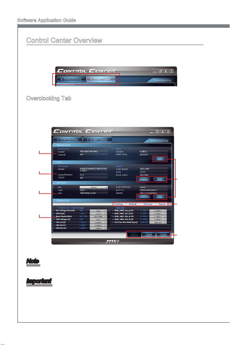
After installing and activating Control Center, you will see Overclock and Green Power
tabs at the top. You can click the tab to switch the control panel.
Overclocking Tab
When you launch Control Center, you will see the Overclock tab at rst, this tab consists
of four blocks which are Mainboard, CPU, Memory and Overclock. You can monitor the
system status, adjust DRAM Timing and voltage under this panel.
Mainboard
information
CPU
information
Advanced
Memory
information
buttons
Overclock
Control
Panel
Overclocking
Mode bar
Prole
buttons
Note
Advanced and DRAM Timing button only appear when you use a Intel mainboard.
Important
The pictures in this guide are for reference only and may vary from the product you purchased. Please refer to the actual screens of your system for detailed information.
2
Page 9
Control Center
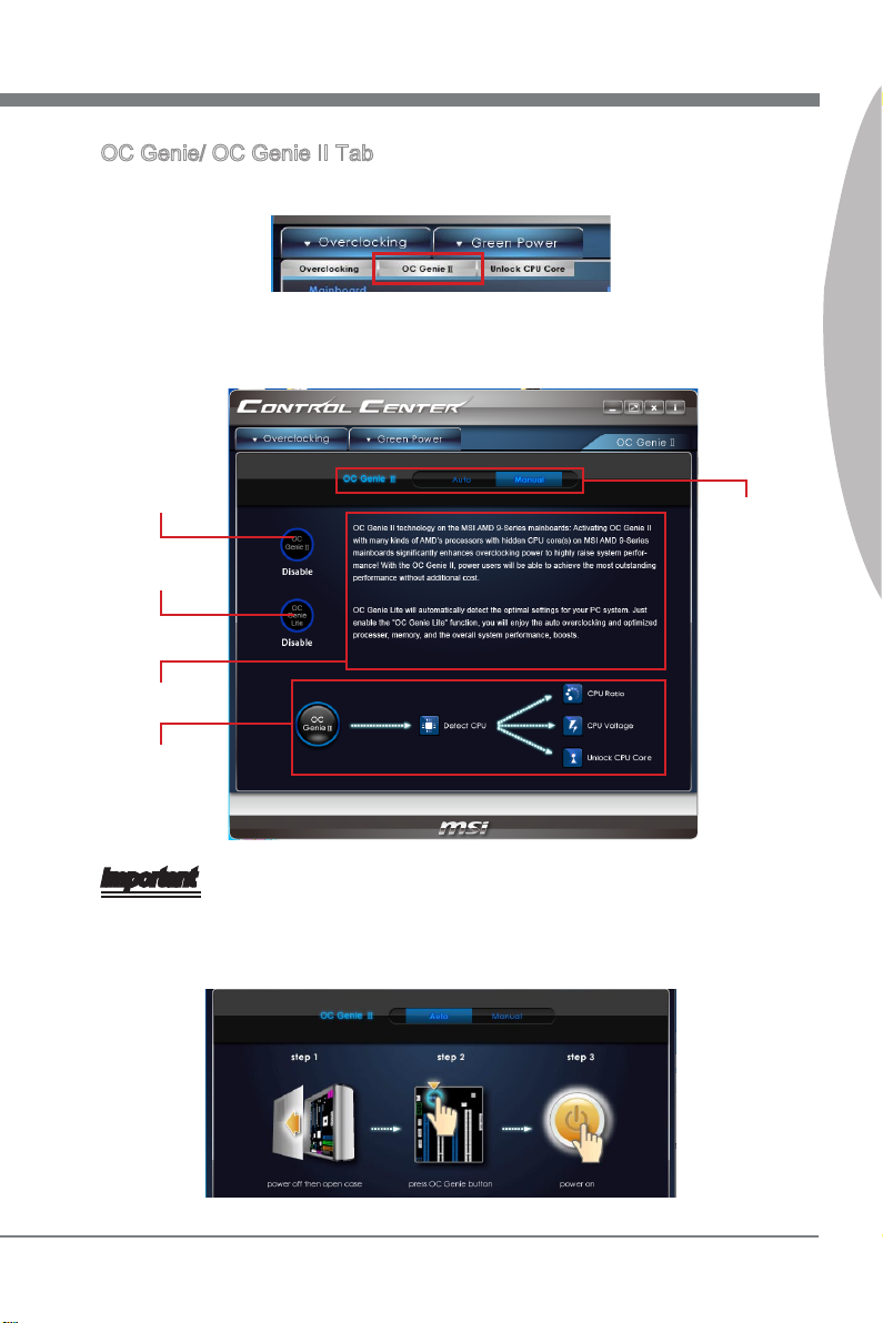
OC Genie/ OC Genie II Tab
To enter the OC Genie/ OC Genie II tab, click the sub-menu under the Overclocking
tab.
Under the OC Genie/ OC Genie II tab, read the introduction on the tab rst. The functions of Intel CPU and AMD CPU may be dierent, that will have dierent screens. The
following gure shows an example of AMD CPU.
OC Genie/ OC
Genie II switch
OC Genie Lite
switch
Introduction
OC Genie/ OC
Genie II steps
diagram
Control
Mode
Selection
Control Center
Important
If there is a physical OC Genie button on your mainboard and when you select the Auto
mode, the OC Genie/ OC Genie II tab will show the animation as below. Follow the
steps and press the button to control OC Genie/ OC Genie II function by the Control
Center software.
3
Page 10
Software Application Guide
Control Center
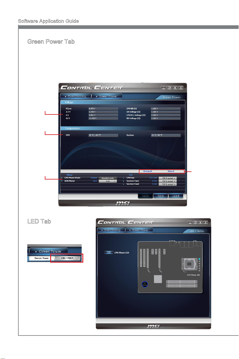
Green Power Tab
Green Power is an energy saving technology that controls power supply by auto phase
switching for CPU and components. Besides, Green Power can automatically manage
your power conguration, resulting in more ecient power usage and acoustic noise
reduction. You can monitor the power supply status, system temperature and adjust
the fan speed under this panel.
Power
Supply
information
Temperature
information
Power Phase,
Fan Speed
control panel
LED Tab
To enter the LED/TEMP tab,
click the sub-menu under the
Green Power tab.
Under the LED/TEMP tab,
you can turn on/o the onboard LEDs by clicking each
button. If your mainboard with
Dr.MOS, this screen will display the status of Dr.MOS.
Green
Power
Mode bar
4
Page 11
Control Center
System Information
This section describes how to monitor the system information, enter the advanced menu
and adjust the DRAM timing.
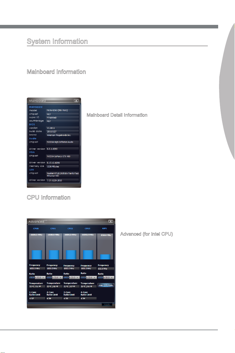
Mainboard Information
Mainboard information block is under the Overclock tab. You can refer to the model
name, chipset, and BIOS version of each item to be informed to the hardware status
at all time.
Mainboard Detail Information
Click the “More” button on the right side of the Mainboard
block to open the mainboard detailed information window,
including model name, chipset, BIOS, audio chip, graphic
chip and LAN chip information.
CPU Information
CPU information block is under the Overclock tab. You can read the information of
model and frequency.
Control Center
Advanced (for Intel CPU)
Click the Advanced button on the right side
of the CPU block to open the Advanced
window. This window shows real-time status of CPU cores and iGPU (only on IGP
chipsets), including frequency, ratio and
temperature.
5
Page 12
Software Application Guide
Control Center
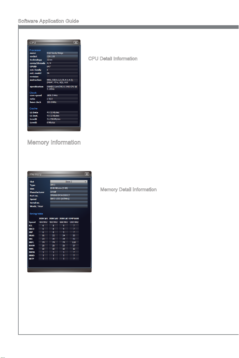
CPU Detail Information
Click the “More” button on the right side of the CPU block
to open the CPU detailed information window, including
model name, specications, features and cache information.
Memory Information
Memory information block is under the Overclock tab. You can read the information of
each memory DIMM slot, including memory type, manufacturer and speed. You can
select a DIMM slot you want to read by clicking slot button.
Memory Detail Information
Click the “More” button on the right side of the
Memory block to open the memory detailed information window, you can select a slot to read information, including type, size, manufacturer, speed
and timing table.
6
Page 13
Control Center
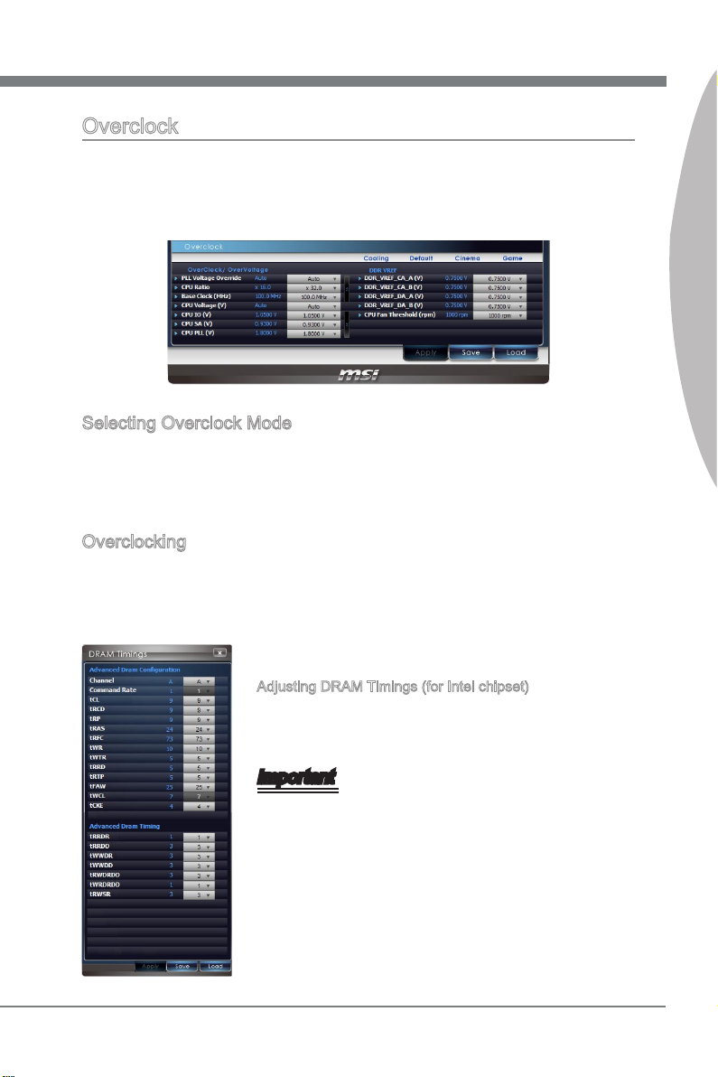
Overclock
Under Overclock block, you can select Cooling, Default, Cinema, and Game mode to
reach the most suitable overclocking eect. That is to say, you can set an overclocking
environment in advance, which avoids unnecessary risks and time-consuming manual
adjustment on endless testing.
Selecting Overclock Mode
Under Cinema mode, Control Center provides you 3% plus overclocking eect automatically, 6% plus under Game mode, and 3% less under Cooling mode (for power saving
concerned users) respectively. You can just enjoy the fast and convenient overclocking
eect or make more adjustments based on your need.
Overclocking
Under Overclock block, also you can adjust the CPU base clock、iGPU frequency (only
on IGP chipsets), and its related voltages like CPU Vcore, PCH, DRAM and so on. In
addition, you are able to adjust memory voltage and even memory reference voltages.
The fan speed is also adjustable to meet your power saving or performance demand.
Control Center
Adjusting DRAM Timings (for Intel chipset)
Click the DRAM Timing button on the right side of the Mem-
ory block to open the DRAM Timings window, you can read
and set parameters.
Important
Please refer to the BIOS chapter in the mainboard user
•
guide.
Every time you shut down the system, the congured set-
•
ting will be restored to the factory default. If you want to
use the saved settings, you have to load it every time by
clicking the “Load” button.
7
Page 14
Software Application Guide
Control Center
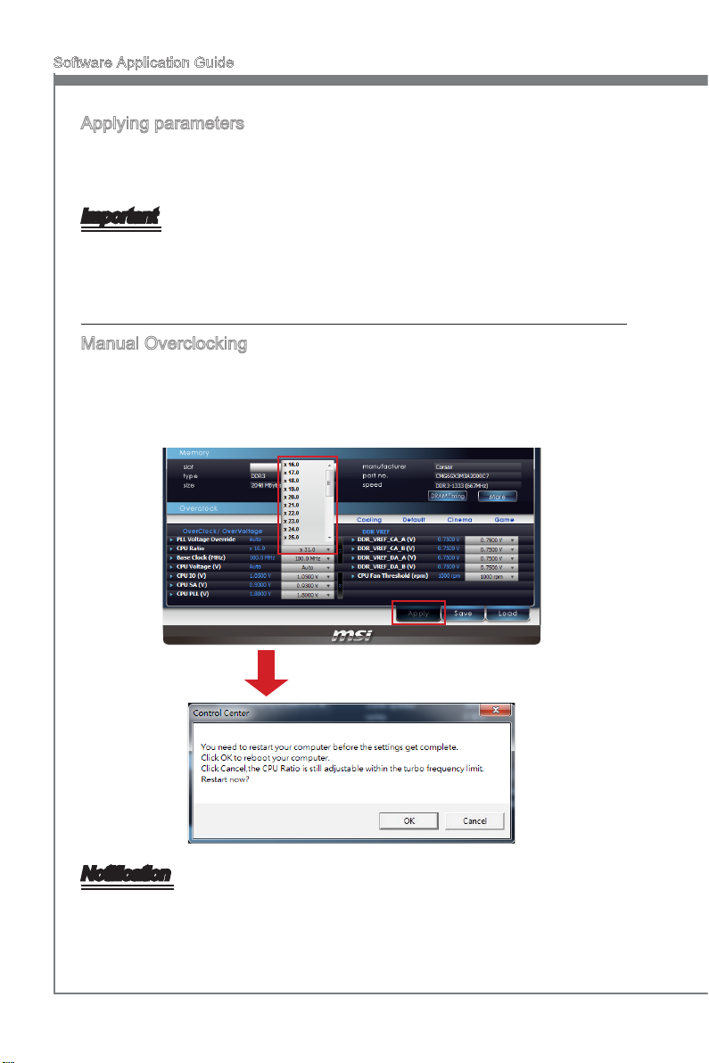
Applying parameters
You can do all the above mentioned adjustments under each mode, after that, please
click the “Apply” button to execute the congured setting without rebooting the system;
or you can click the “Save” button to save the adjustments for future use.
Important
Every time you shut down the system, the congured setting will be restored to the
factory default. If you want to use the saved settings, you have to load it every time by
clicking the “Load” button.
Manual Overclocking
You can adjust the CPU base clock, CPU ratio and its related voltages to create an
even better overclocking environment, after that, please click the “Apply” button. When
prompted to reboot your computer, click OK to reboot. You can also click the “Save” button to save the adjustments for future use. You may refer to the following pictures.
Adjust CPU Ratio, click Apply, it will
prompt a message for reboot.
Notication
A good CPU cooler is suggested when users have to overclock manually, the key to
overclocking through Control Center is to increase the smallest increments allowable
on related items.
8
Page 15
Control Center
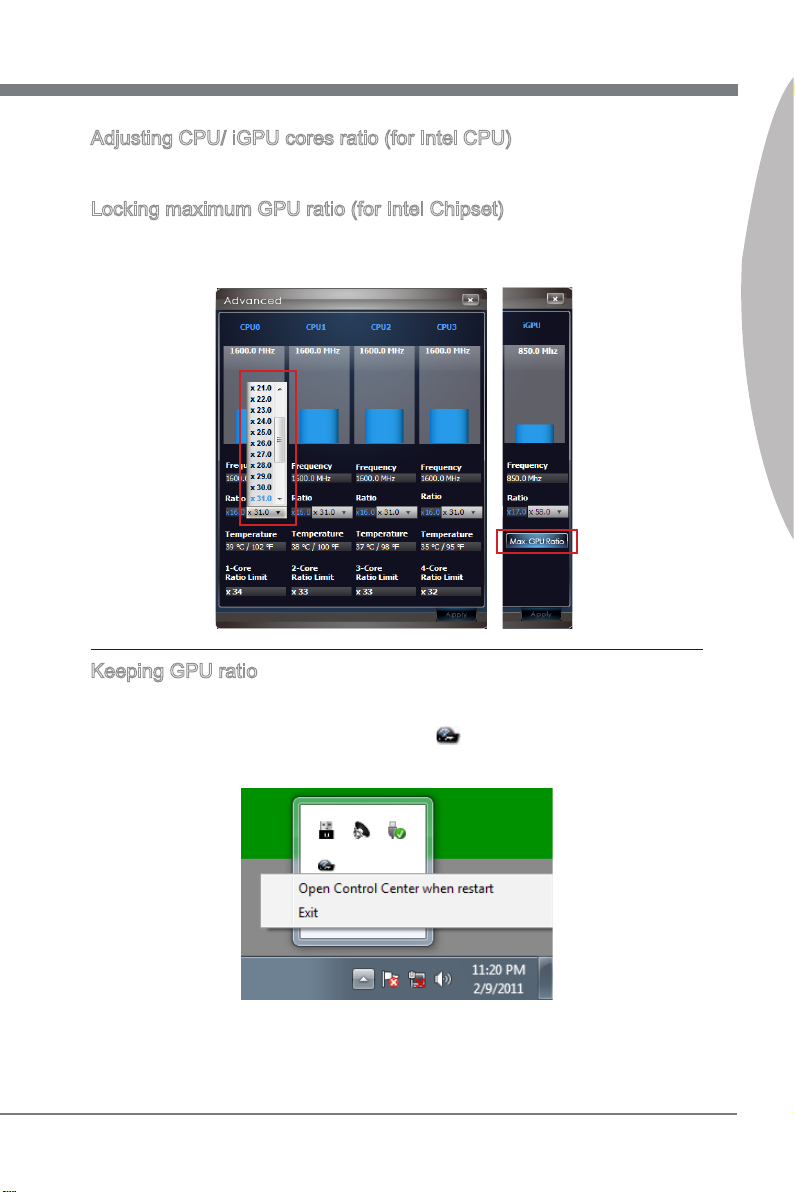
Adjusting CPU/ iGPU cores ratio (for Intel CPU)
Click the Advanced button on the right side of the CPU block to open the Advanced
window. You can adjust the CPU/iGPU cores ratio.
Locking maximum GPU ratio (for Intel Chipset)
To lock GPU ratio at the maximum value, click Max. GPU Ratio button in Advanced
window, otherwise it will be dynamically adjusted.
Keeping GPU ratio
In the default setting, for keeping the GPU ratio, Control Center will startup automatically when your system boots and you login. It is minimized to the system tray instead
of the taskbar. If you want to close it, right click icon on the system tray and then
click Exit.
Control Center
9
Page 16
Software Application Guide
Control Center
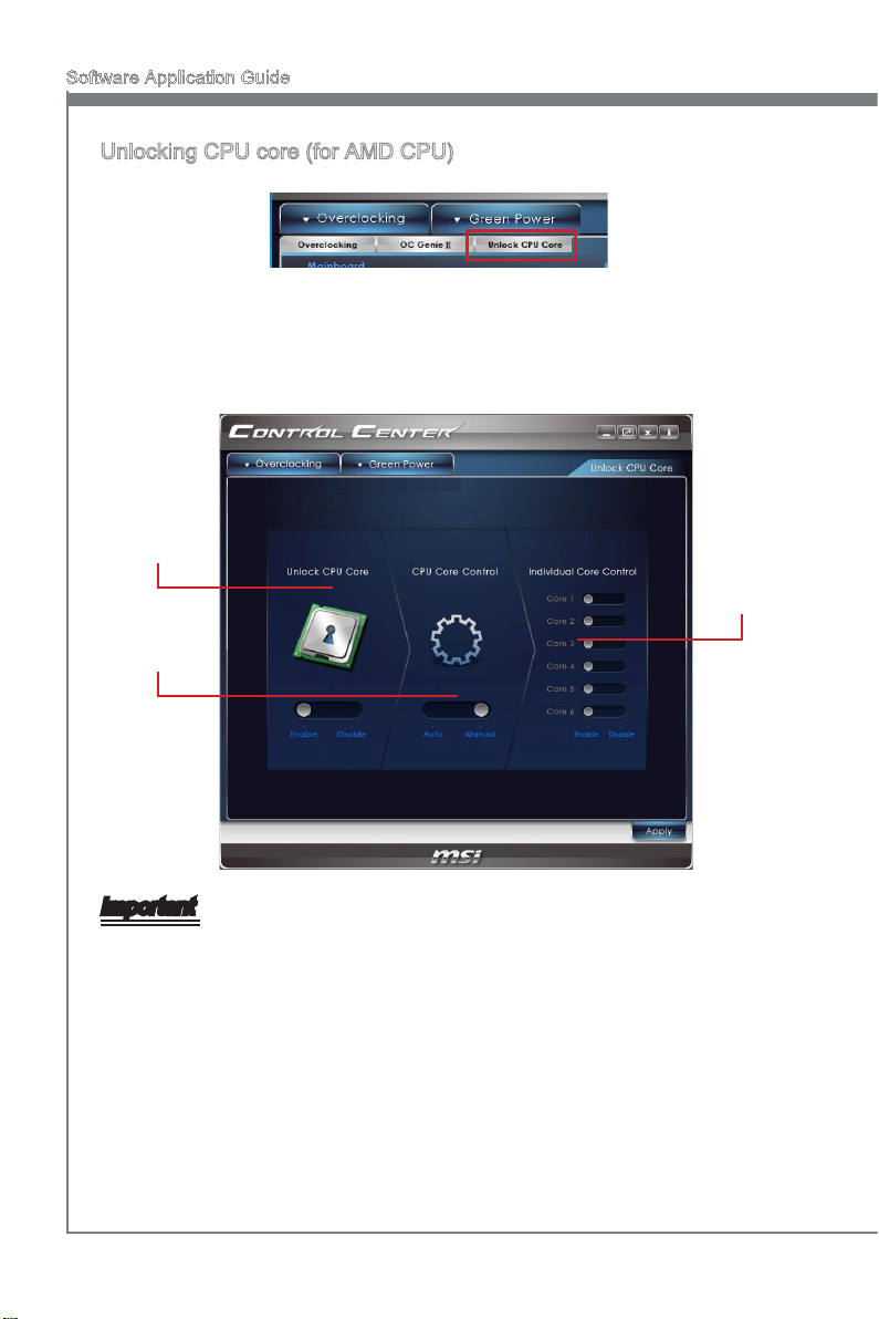
Unlocking CPU core (for AMD CPU)
To enter the Unclock CPU Core tab, click the sub-menu under the Overclocking tab.
Under the Unclock CPU Core tab, you can unlock CPU core that is original hidden (or
disabled) in CPU to enhance the performance. Therefore, a dual or tri-core CPU turns to
be a quad-core CPU, a quad-core CPU turns to be a hex-core CPU. In another words,
you can gain a quad-core or hex-core CPU.
Unlock CPU
Core control
panel
CPU Core
Control panel
Individual
Core
Control
panel
Important
The success and the stability of core unlocking regard to the CPU physique itself. Not
any CPU could be unlocked successful; by the way, the stability of the unlocked CPU
may be tested later. You can use some burn-in programs or Benchmark to test the
stability of the unlocked CPU.
To unlock CPU core, simply select the Unlock CPU Core column to be "Enable". You
can enable/ disable each core individually when the CPU Core Control column is set
to manual. After that, please click the “Apply” button. When prompted to reboot your
computer, click OK to reboot.
10
Page 17
Control Center
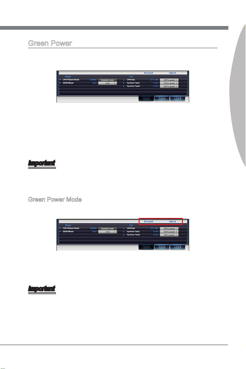
Green Power
Under the Green Power tab, you can select the Green Power mode, read CPU Phase
status, also select other power phase and control fan speed.
This application provides APS, Intel SVID, and Disable mode for CPU power phase
display. In APS and Intel SVID mode, when you adjust CPU voltage, the CPU phase
control will switch to Disabled mode automatically. You can change the CPU fan and
system fan speed as well to get a good balance between performance and power saving. After setup is complete, click the “Apply” button at the bottom of the tab to apply
changes or click the “Save” button to save the adjustment for future use.
Important
Every time you shut down the system, the congured setting will be restored to the
factory default. If you want to use the saved settings, you have to load it every time by
clicking the “Load” button.
Green Power Mode
There are two preset mode for fan control.
Control Center
Default: CPU fan speed: 100%, System fan speed: 100%
Silent: CPU fan speed: 50%, System fan speed: 50%
Important
The Control Center provides a safety funcation. A warning pop-up message will appear
when the CPU temperature reaches 75 degrees. Meanwhile it will automatically switch
to Default mode for maximum fan speed.
11
Page 18
Software Application Guide
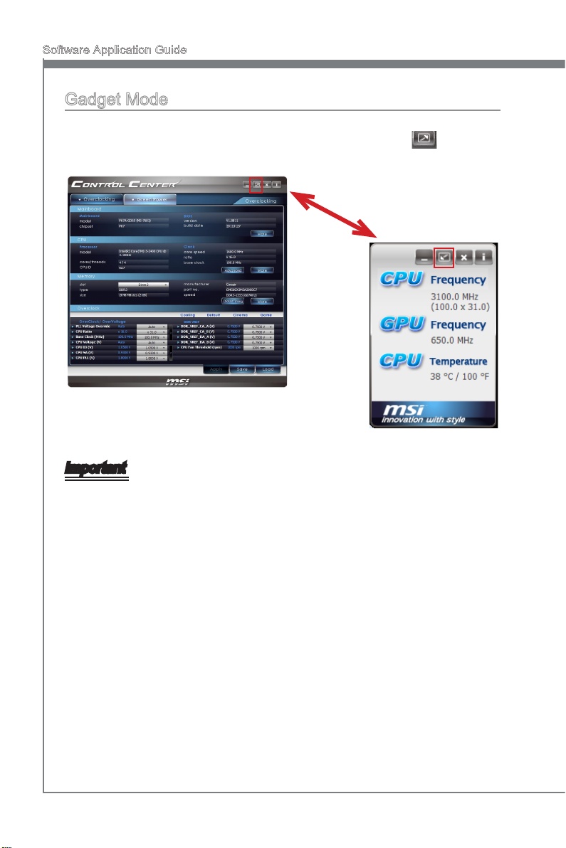
Gadget Mode
Control Center provides a gadget mode to monitor the CPU frequency, iGPU frequency
and CPU temperature. Switch to gadget mode by clicking the button as shown in
picture.
Important
The GPU frequency only appears when you use the CPU with integrated GPU.
12
Page 19

Super-Charger
Super-Charger provides i-Pad, i-Phone and iPod charging function.
The iPad with very special charging requirements as it
requires 1.6A power supply rather than the 0.5A current available with conventional USB interfaces. That
is ordinary computer cannot charge your iPad even at
power on status. The MSI Super-Charger is a Windows
resident program capable of revising power supply mode
of your USB port. Once an iPad is connected to your
USB port the Super-Charger sends a signal to initiate its
charging circuit.
When system goes into suspend, hibernate state or even
shutdown, Super-Charger will be still able to provide
charging function.
Page 20
Software Application Guide
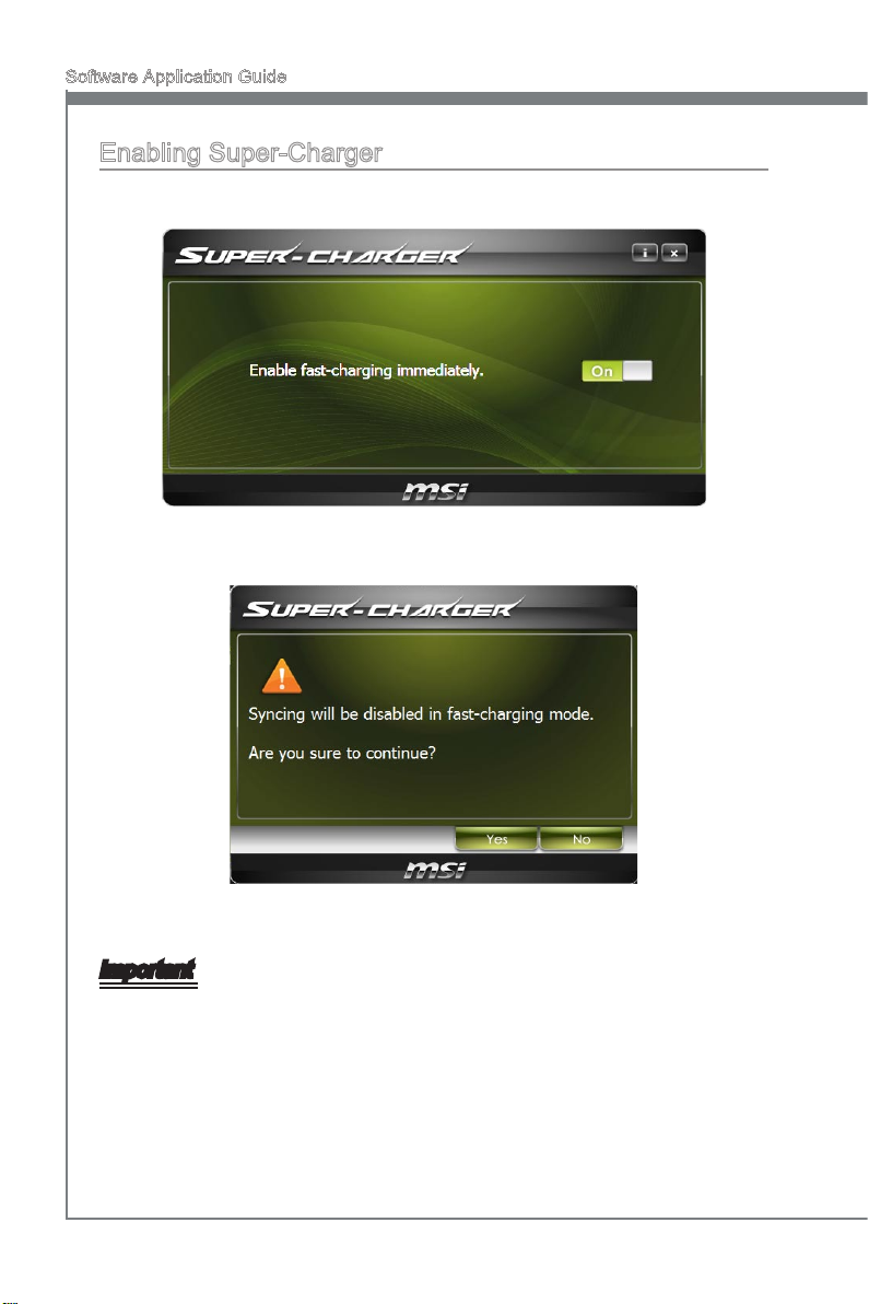
Enabling Super-Charger
Install and launch Super-Charger, the dialog as below will appear.
To enable Super-Charger, click the “On/O” button to On.
When a warning prompt window appears, click “Yes” to continue.
Important
When Super-Charger is enabled, the USB port will be changed to Charging mode,
therefore, the data syncing will be disabled.
14
Page 21

Winki III
Winki III is an MSI self-developed Linux distribution for
MSI’s proprietary mainboards. The quick boot Winki III
provides Live update, Internet browser, instant messenging, Skype, photo viewer and so on. Without entering
the Microsoft Windows, users still have access to basic
programs that are frequently used.
Page 22
Software Application Guide
Winki Ⅲ
System Requirement
In order to run Winki III, the following hardware and is required
At least 2GB memory
■
DVD Drive
■
Important
If you are using the Intel SATA 6Gb/s or Marvell 88SE9128 chip, when you use Live
Update or HDDBackup utility under Winki III, please change IDE_Mode to AHCI_Mode
in BIOS setting.
Entering Winki III
You can enter Winki III OS from attached DVD or your USB key installed with Winki III
OS. Please follow the steps below:
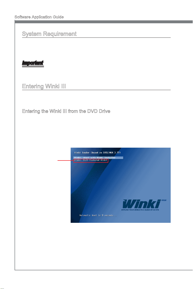
Entering the Winki III from the DVD Drive
Put the attached DVD to the DVD drive.
1.
Reboot and enter the BIOS by pressing “Delete” under POST screen.
2.
Select to boot from DVD drive and reboot.
3.
The Winki III boot screen appears as below.
4.
Select “Winki, full-featured Winki” and press “Enter”.
5.
Select this option
16
Then, you will enter Winki.6.
Page 23
Winki Ⅲ
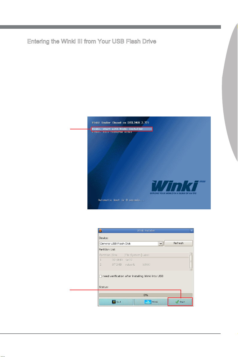
Entering the Winki III from Your USB Flash Drive
You need to prepare a USB drive with at least 1GB capacity. Please backup your data
in advance or the Winki III installer will format your USB drive.
Insert your USB drive to your computer.
1.
Put the attached DVD to the DVD drive.
2.
Reboot and enter the BIOS by pressing “Delete” under POST screen.
3.
Select to boot from DVD drive and reboot.
4.
The Winki III boot screen appears as below.
5.
Select “Winki, Start with Winki installer” and press “Enter”.
6.
Select this option
Winki Ⅲ
Check the installing dialog and click “Start”. 7.
Click here
17
Page 24

Software Application Guide
Winki Ⅲ
Make sure that you backup your data in advanced. Then, click “Yes” to continue.8.
Click here
The installer is proceeding. Click “Close” when nish.9.
Click here
Click “Reboot” and then “Yes”.10.
Click here
Enter the BIOS by pressing “Delete” under POST screen.
11.
Select to boot from USB drive and reboot.
12.
Then, you will enter Winki III.
13.
18
Page 25

Winki Ⅲ
Winki III overview
The following gure describes the function of the Winki III.
Application selection
Calendar
Task bar
Winki Ⅲ
Recently opened le list
Tool and Device selection
Application selection
▶
Applications are classied into several categories. Select a category and the applica-
tions will be listed at the top. You can click the icons to launch respective applications.
Task bar
▶
This bar is used to monitor the status of system and display current time.
Calendar
▶
The calendar allows you to schedule your tasks and set reminders.
Tool and Device selection
▶
Move the cursor to the left of the desktop, the pop-up menu appears. You can use it to
capture the screen and mount / unmount device drives.
Recently opened le list
▶
There is a list of recently used applications at the bottom. It allows you to launch ap-
plications quickly.
RSS reader
▶
The RSS reader is able to display any RSS news feed.
RSS reader
19
Page 26

Software Application Guide
Hotkeys
You can also use the hotkey listed below.
Hotkey Function
Ctrl + 1 Web Browser
Ctrl + 2 Instant Messenger
Ctrl + 3 Skype
Ctrl + 4 Photo Viewer
Ctrl + F1 Volume Controller
Ctrl + F2 Resolution Setting
Ctrl + F3 Network Setting
Ctrl + F4 Language Setting
Ctrl + F5 Keyboard Setting
20
Ctrl + F11 Decrease Volume
Ctrl + F12 Increase Volume
Page 27

Audio Genie
Audio Genie provides speakers location setting and THX
mode selection.
This chapter describes how to install Audio Genie and
how to use it.
Page 28

Software Application Guide
Audio Genie
Installing Audio Genie
If your audio device is built-in with your mainboard, take a moment to conrm that the
item “Audio Controller” in BIOS has been set to “Enabled”. If you are using the Realtek
HD audio card, conrm the card has been installed properly.
Before you begin to install and use Audio Genie, you need to install Realtek Audio and
THX TruStudio PRO.
Using Audio Genie
The Audio Genie contains three screens Location, Audio Mode and THX.
Location
The Location Setting allows you to nd the suggested speaker placement for your stereo and select audio les for testing.
22
This screen only shows
the speakers placement
Page 29

Audio Genie
Audio Mode
The Audio Mode allows you to select six THX audio modes, You can also select the
audio modes by right-click the Audio Genie icon in the system tray.
THX
This screen introduce the functions of THX control panel. When you enter this screen
the THX control panel will appear on the desktop.
Audio Genie
23
Page 30

Software Application Guide
Hotkeys
You can also use the hotkey listed below.
Hotkey Function
Ctrl + F7 Game Mode
Ctrl + F8 Movie Mode
Ctrl + F9 Music Mode
Ctrl + F10 Clean Mode
Ctrl + F11 Phone Mode
Ctrl + F12 Optimum Mode
Using THX Control Panel
You can open the THX control panel through the Audio Genie, or double-click the THX
icon in the system tray.
To enable or disable each THX sound eect, click the sound eect on the THX control
panel, and then click the on/ o button. Also you can adjust the intensity by dragging the
slide bar to the right or the left.
24
Page 31

Video Genie
Video Genie provides the automatic color saturation enhancement, contrast enhancement and intelligent gamma correction.
Video Genie not only improves the quality of static image, the video playback will be dramatically enhanced.
Page 32

Software Application Guide
Video Genie overview
The following gure describes the function of the Video Genie.
Eect comparison
Picture selection
Cancel button
OK button
Apply button
Enable checkbox
Eect comparison
▶
This window shows the picture comparison between before and after Video Genie ap-
plication.
Picture selection
▶
This button allows you to select a picture to be displayed in eect comparison window.
Cancel button
▶
This button is used to close Video Genie main window, you can still return to the main
window by clicking the Video Genie icon in the system tray.
OK button
▶
When you click the OK button, the eect setting will be applied and the main window
will be closed.
Apply button
▶
This button allows you to apply the eect setting immediately.
Enable check box
▶
You can use this checkbox to either enable or disable the Video Genie.
Enabling Video Genie
This section describes how to enable the Video Genie. Please follow the steps below:
Check the Enable checkbox.
1.
Click the OK button.
2.
The Video Genie “ON” message will pop up for two seconds.
3.
26
Page 33

Network Genie
Network Genie is an utility to optimize the trac for bandwidth control. Network Genie is designed for the Realtek
LAN chip with Windows Vista and Windows 7 platforms.
With the Network Genie you can play on-line games and
download data without being disturbed by latency. Just
set up the network priority in Network Genie. You do not
need to close some of occupied bandwidth applications
while enjoying on-line games or streaming videos.
Page 34

Software Application Guide
System Requirement
In order to run the Network Genie, the following hardware and software is required
Hardware:
MSI mainboard with Realtek LAN chip (8111E or newer).
■
Software specications:
Windows 7 32bit/ 64bit
■
Windows Vista 32bit/ 64bit
■
Realtek LAN driver
■
Network Genie Operation
Once installed, the Network Genie logo shows on system tray (the right bottom corner of
the screen). Mouse right click at the icon, will display the following screen.
Moving the mouse pointer on “Mode” option, a sub-menu will appear for user to
■
select Game, Stream, Browser and Auto mode.
Clicking on the “Show” option will open a new window with Network Genie con-
■
trol panel.
Clicking on the “Hide” option will hide the Network Genie control panel.
■
Clicking on the “Exit” option will exit Network Genie.
■
Invisible logo means Network Genie is not activated.
■
In case no logo is shown on the system tray, it is possible to activate Network Genie
manually by clicking Start → Programs → MSI → Network Genie → Network Genie.
28
Page 35

Network Genie Control Panel
Mode Tab
If Mode tab is selected, the following screen is displayed:
Mode selection
▶
Mode selection is used to quickly change the network mode. The following options are
available:
Game Mode - Network Genie will set gaming applications to high priority.
■
Stream Mode - Network Genie will set streaming applications to high priority.
■
Browser Mode - Network Genie will set web browsers to high priority.
■
Auto Mode - Network Genie will set gaming, streaming applications and web
■
browsers to high priority.
Network Genie
Click “Apply” button to complete.
29
Page 36

Software Application Guide
Application Tab
If Application tab is selected, the following screen is displayed:
Application tab lists all network related applications. There are 5 columns in the list,
including Program, Priority, Blocked, Download and Upload. The function of each
column is described as follows:
Program - Shows the currently running network related applications.
■
Priority - “H”: represents high network priority. “L”: represents low network prior-
■
ity. You can manually change the priority by clicking “H” or “L”.
Blocked - “Lock icon”: represents the network application is blocked. “Un-lock
■
icon”: represents the network application is allowed. You can block the network
application by clicking the block icon.
Download/ Upload - Indicate the download and upload status.
■
Inactive programs will be listed at the bottom and you can check the “Hide inactive
programs” to hide them. After changing the settings, click the “Save” button to store the
newer congurations.
30
Page 37

Advanced Tab
If Advanced tab is selected, the following screen is displayed:
Advanced tab provides detailed settings for Network Genie. There are two parts in this
tab, one is “Internet Speed”, and another is “Delay/Sensitivity Settings”.
In “Internet Speed”, you can set the maximum available bandwidth to the upload/
download speed manually or just leave blank for no limit.
In “Delay/Sensitivity Settings”, you can enable “Speed up Response Time” and “No
TCP Delay” to reduce the latency of the high priority applications.
Network Genie
31
Page 38

Software Application Guide
System Info Tab
If System Info tab is selected, the following screen is displayed:
System Info tab shows system information, including “Processor”, “Network Card”,
“Memory”, “Graphics Card”, “Operating System”, “CPU Usage”, “Connection Status”,
“Total Packets Sent”, and “Total Packets Received”.
About Tab
If About tab is selected, the following screen is displayed:
About tab shows information of Network Genie, including “Version”, “Copyright”, and
web address.
32
Page 39

Teaming Genie
Teaming Genie provides trac load balancing and redundant NIC operation if a network connection fails.
When multiple NICs are installed in the same mainboard,
they can be combined into a team. The team must include at least two members, but can support up to ten
members.
In a team of two or more NICs, the secondary NIC lls
the primary, if the primary NIC fails.
Page 40

Software Application Guide
Teaming Genie
System Requirement
The system and software requirements for Teaming Genie as listed below.
Installed with Microsoft .NET Framework 3.5
■
Dual Realtek RTL81XX series with NIC Adapters
■
Installing Teaming Genie
Before you begin to install and use Teaming Genie, take a moment to conrm that the
items “Onboard LAN Controller” in BIOS has been set to “Enabled”.
You need to install Microsoft .NET Framework 3.5 and Realtek LAN driver prior to
Teaming Genie installation. After then, Install Teaming Genie.
Teaming modes
FEC/GEC Mode
▶
The FEC/GEC mode is similar to the Link Aggregation\LACP(802.3ad) mode in that
all adapters in the team need to be congured to receive packets for the same MAC
address, however, it does not provide LACP or marker protocol support. Basically, this
mode is a light version of the Link Aggregation\LACP(802.3ad) mode.
The FEC/GEC mode supports load balancing and failover for both outbound and inbound trac.
Link Aggregation\LACP(802.3ad) Mode
▶
This mode supports link aggregation and conforms to the IEEE 802.3ad (LACP) speci-
cation. All adapters in the team are congured to receive packets for the same MAC
address. In this mode, at least one of the link partners must be in active mode.
34
Page 41

Teaming Genie
Teaming Genie Overview
The following gure describes the function of the Teaming Genie.
Mode selection
Member selection
Create/ Remove button
Mode selection
▶
Here you can select a team mode.
Member selection
▶
Here you can select members.
Create/ Remove button
▶
This button is used to create or remove a team.
Teaming Genie
35
Page 42

Software Application Guide
Creating Team
This section describes how to create a team. Please follow the steps below:
Select FEC/GEC mode or Link Aggregation\LACP(802.3ad) mode
1.
Select members that you want to combine to.
2.
Click the Create Team button.
3.
To remove the team, click the Remove button at the bottom.
36
Page 43

Live Update 5
Live Update 5 is an application for the MSI system to
scan and download the latest drivers, BIOS and utilities.
With Live Update 5, you don’t need to search the drivers on web sites, and don’t need to know the models of
mainboard and graphics cards. Live Update 5 will download the appropriate drivers automatically.
Page 44

Software Application Guide
Live Update 5
Live Update 5 overview
After installing and activating Live Update 5, you will see Home, Live Update, History,
Setting and About tabs at the top. You can click the tab to switch the control panel.
Home Tab
When you launch Live Update 5, you will see the Home tab at rst, this tab displays the
information of the system.
Live Update Tab
This tab allows you to select les to download. You can also read the relevant information by clicking the information icon on the right of the item listed.
Download options
Download list
Scan / Download /
Total installer button
38
Page 45

Live Update 5
History Tab
This tab shows the downloading history.
Setting
This tab allows you specify the frequency that Live Update 5 remind you to update.
Live Update 5
Reminder Frequency
conguration
Important
The pictures in this guide are for reference only and may vary from the product you purchased. Please refer to the actual screen of your system for detailed information.
39
Page 46

Software Application Guide
Live Update 5
About
This tab shows the information about Live Update 5. You can click the “MSI Online
Customer Service” button to open the online customer service web page.
MSI Online Customer
Service link button
40
Page 47

Live Update 5
Updating The System
This section describes how to update your system with Live Update 5. Please follow
the steps below:
Select download options in Live Update tab. If you select “Automatic scan”, Live
1.
Update 5 will automatically detect your system, select the appropriate items to
download.
Click the “Scan” button at the bottom, you will see the screen below. It may take
2.
several moments to complete the process. Please wait while it is displayed.
When the download list appears, please check the items you intend to update. 3.
Select all
Click “Download” button at the bottom.
4.
When Save Path prompt, you need to specify the directory for Live Update 5.
5.
Live Update 5
When downloading you will see the screen below. It may take several moments to
6.
complete the process. Please wait while it is displayed.
To install the applications, simply unpack the packages and install. 7.
41
Page 48

Total Installer
Total Installer is a convenient feature to simplify frequent installing procedure. To use
Total Installer:
Scan updates in Live Update tab.1.
Select all
Total installer button
Check the items you intend to update.
2.
Click the Total Installer button. Live Update 5 will automatically install them.
3.
When prompted, click OK to complete the Total Installer procedure
4.
Reboot your system.
5.
Page 49

EasyViewer
MSI EasyViewer is a full 3D image browser that supports
NVIDIA 3D vision and allows zoom-in, zoom-out, fullscreen or auto-playback for previewing images. Under
the Slide mode, you may edit pictures: image enlargement, reduction, 90-degree and ne-tuned rotation. You
can even use the HDII image enhancement, intelligent
white balance, and image sharpness adjustment features to make your pictures richer, more alive and more
textured. With intuitive user interface, it can be easily operated on a touch screen or on any PC with mouse.
Page 50

Software Application Guide
Video Genie
Supported File Formats
EasyViewer’s current supported le formats are jpg, png, bmp, tif and gif.
Preview Mode
Zoom In
Auto Playing Full Screen
Changing Directory Upper Directory
1. Zoom In/Out
Scroll with the mouse wheel.
■
Press the button and button.
■
2. Browsing photos
Left-click the mouse and hold. Move the mouse to the left or right to browse
■
photos.
Drag the slider bar to browse photos.
■
3. Selecting a photo
Left-click on an image to select it.
■
Zoom Out
44
Page 51

Video Genie
4. Auto playing images
Press the button and the EasyViewer will present a full-screen slide
■
show that runs automatically.
5. Full Screen
Press the button and the EasyViewer will enter full-screen mode.
■
6. Changing the le folder
Press the button to change your destination folder.
■
7. Go to the upper directory
Press the button to go to the upper directory.
■
Video Genie
45
Page 52

Software Application Guide
Video Genie
Slide Mode
Zoom In/Out Rotation
Fine-tuning Rotation Enhancing HDII Image
Intelligent White Balance Saving Files
Auto Playing Full Screen
1. Entering Slide mode
While selecting an image in the Preview mode, double left-click the mouse to
■
enter the slide mode.
2. Browsing photos
Left-click the mouse and hold. Move the mouse to the left or right to browse
■
photos.
Select the thumbnail to get a larger-sized view.
■
Press the arrow keys (←→) on the keyboard.
■
Press the and buttons alongside the thumbnail bar.
■
3. Zoom In/Out
Press the button and move the cursor to the center for zoom. Left-click
■
the mouse and hold. Move the mouse arbitrarily to zoom in or out.
Use two-nger pinch zoom (for touch screens only).
■
46
Page 53

Video Genie
4. Rotating photos
Press the buttons to rotate your photos clockwise or counterclock-
■
wise.
Use two-nger rotation (for touch screens only).
■
5. Fine-tuning the photo rotation
Press the button to ne-tune the degree of photo rotation.
■
6. HDII image enhancement
Press the button to enhance HDII images. If the image exposure is ad-
■
equate, the image will remain unchanged.
7. Intelligent white balance
Press the button to activate intelligent white balance. If the white balance
■
of the image is adequate, the image will remain unchanged.
8. Auto playing images
Press the button and the EasyViewer will present a full-screen slide
■
show that runs automatically.
9. Full Screen
Press the button and the EasyViewer will enter full-screen mode. If
■
equipped with a 120Hz monitor, the True 3D mode will be activated automatically. To experience the 3D eect, a pair of shutter glasses will be required.
10. Saving les
Video Genie
Press the button to save the images you’ve processed.
■
47
Page 54

Software Application Guide
3D Eect
EasyViewer provides the 3D visual eect, with 3D glasses, you can experience the
photos in 3D.
System Requirement
The system and software requirements for EasyViewer 3D eect as below list.
Microsoft® Windows® Vista 32/64-bit or Windows 7 32/64-bit
■
3D Vision-Ready Display
■
NVIDIA® 3D Vision Kit
■
Compatible NVIDIA® GeForce Graphics Card
■
Enabling 3D Effect
To enable 3D eect, please follow the steps below:
Conrm the graphic card has been installed properly.
1.
Conrm the 3D Vision kit has been installed properly.
2.
Install the latest graphic card driver.
3.
Install the GeForce 3D Vision driver.
4.
Enable GeForce 3D Vision in the NVIDIA control panel.
5.
Enter the MSI EasyViewer full-screen mode.
6.
Enjoy the 3D eect.
7.
Important
The MSI EasyViewer can only support GeForce 3D Vision in the full screen mode.
48
Page 55

VIRTU
Lucid VIRTU is designed for Intel 2nd Generation Intel®
Core™ i7 / Core™ i5 / Core™ i3 processors platform
with Intel Processor Graphics enabled. VIRTU dynamically assigns tasks to best available graphics resource
based on power, performance and features.
VIRTU allows user to fully utilize the unique capabilities of the Intel’s advanced media features on Intel 2nd
Generation Intel® Core™ i7 / Core™ i5 / Core™ i3 along
with the high end 3D rendering performance provided by
the discrete GPU installed in the system.
When no high end graphics is used and display is connected to integrated GPU, the discrete GPU is put in idle
mode thus GPU utilization, heat, fan speed and power
are down to near zero, turning the system to an environment friendly platform.
Page 56

Software Application Guide
VIRTU
System Requirement
In order to run the Lucid VIRTU, the following hardware and software is required
Hardware specications:
The mainboard supports VIRTU
■
Intel 2nd Generation Intel® Core™ i7 / Core™ i5 / Core™ i3 processors in an
■
LGA 1155 socket.
AMD GPU (HD 4xxx and up) or Nvidia GPU (GF 2xx and up)
■
At least 2GB memory
■
Software specications:
Windows 7 32bit/ 64bit
■
DirectX 9/ 10/ 10.1/ 11
■
Intel/ NVIDIA/ AMD GPU drivers
■
i-Mode
i-Mode provides user with near zero performance overhead on 3D graphics games,
Intel® Core™ i7 / Core™ i5 / Core™ i3 special features and power saving options when
no 3D gaming is used.
Important
In i-Mode the ATI/nVidia Control Panel is not accessible.
To use Lucid VIRTU in i-Mode, display must be always connected to mainboard video
output as shown below.
50
Graphics card
NO DISPLAY CONNECTED
Display connected to
mainboard video port
Page 57

VIRTU
d-Mode
d-Mode is provided for demanding 3D gamers to achieve uncompromised 3D performance of discrete GPU installed in the system. In this mode, VIRTU allows user to utilize
Intel special features, while display is connected to discrete GPU.
Important
In most cases the dierences of 3D performance between i-Mode and d-Mode are
unnoticeable to the user, so it is recommended to use i-Mode to save power.
To use Lucid VIRTU in d-Mode, display must be connected to graphics card installed in
the system as shown below.
Display connected to
graphics card
Installing VIRTU
In BIOS → Settings → On-Chip VGA Devices → IGD Multi-Monitor, the IGD Multi-
■
Monitor must be set to Enabled.
Intel/ NVIDIA/ AMD GPU drivers must be installed prior to Lucid VIRTU instal-
■
lation.
Install VIRTU from MSI Driver DVD setup screen → Driver → OTHERS. You
■
can also find setup.exe and double-click it to install. The full path on the DVD is
\\OtherDriver\Lucid Virtu Driver.
GPU drivers and Lucid VIRTU should be installed before running any graphic
■
application.
It is recommended to restart the system after every driver installation.
■
VIRTU
Important
Lucid VIRTU is designed for Intel 2nd Generation Intel® Core™ i7 / Core™ i5 / Core™
i3 processors based platforms only.
51
Page 58

Software Application Guide
VIRTU
VIRTU Operation
After the installation process completed, VIRTU is activated. Once activated, the Lucid
logo shows on system tray (the right bottom corner of the screen). Mouse right click at
the icon, will display the following screen.
Clicking on the “Open control panel” option will open a new window with VIRTU
■
control panel.
Clicking on “Disable” option, allows the user to stop VIRTU function. When
■
VIRTU is disabled, the system will use the Intel® Core™ i7 / Core™ i5 / Core™
i3 IGP for graphics activities.
Invisible or grey logo means VIRTU is not activated.
■
In case no logo is shown on the system tray, it is possible to activate the driver and the
control panel manually by using the following instructions:
Click Start → Programs → VIRTU.
1.
Right-click on “VIRTU Control Panel”.
2.
In case logo icon is grey, right-click while pointing at the logo to get the following
screen:
Clicking on the “Enable” option, will activate the VIRTU.
52
Page 59

VIRTU
VIRTU Control Panel
Main Tab
When activating the VIRTU control panel, the following window is displayed:
In-Game
Icon selection
Activate
button
Performance
optimization
Activate button
▶
By pressing a big “On” button VIRTU solution is activated. If “Show in System Tray” is
selected, a small control panel icon will be displayed on the system tray together with
the rest of the current running applications.
In-Game Icon selection
▶
In-Game Icon selection is used to enable/disable in game VIRTU logo indication. The
following options are available:
Show - The logo will be constantly displayed in the selected corner of the
■
screen.
Show for a few seconds - The logo will be shown for a few second and then
■
will disappear.
Hide - No logo will be shown.
■
Chose a Corner - is a control to select a corner of the screen in which VIRTU
■
logo will be displayed.
Performance optimization
▶
You can optimize the performance of the virtualization by using special techniques.
Tested on each application in support list. In case of new application some issues may
rarely happen it using full performance setting. In this case it is recommended to change
the seting to Quality.
VIRTU
53
Page 60

Software Application Guide
VIRTU
Games Tab
If the Games tab is selected, the following screen is displayed:
This screen shows the applications that VIRTU supports with the available graphics
cards. The application list is changed according to the graphics cards available in the
system and the current conguration.
VIRTU allows users to add new applications using the "Add", "Edit" and "Remove" buttons. We cannot guarantee the functionality and performance of applications that were
not part of the application list provided with the product.
Important
Adding and editing of the applications list is disabled in evaluation versions of the
product.
54
Page 61

VIRTU
When selecting the “Add” option, the following window is displayed:
Place the desired application full “exe” le path in the “exe name” box. Clicking on the
“…” button next to the “exe name” box allows using a standard Windows browser to
nd the location of the desired application “exe” le.
VIRTU
The “Friendly name” box allows the user to give the desired application a name that
best describes the application. This is a free text box.
Press “OK” after lling the required information. This will automatically add an application to the supported game list. Once the desired application will activate, VIRTU will
be applied to this application.
Important
Adding manually an application that was not originally part of the game list means that the
application did not pass tests. We cannot guarantee the functionality and performance
of applications that were not part of the application list provided with the driver.
55
Page 62

Software Application Guide
About Tab
If the “About” tab is selected, the following screen is displayed:
This screen provides VIRTU version installed.
56
Page 63

Virtu Universal MVP
Lucid VIRTU Universal MVP solution is designed for
the platforms with one integrated and one discrete
GPU. VIRTU Universal MVP dynamically assigns tasks
to best available graphics resource based on power,
performance and features. There is no need for HW or
HW changes. VIRTU Universal MVP allows user to fully
utilize the capabilities of both integrated and discrete
GPUs
When no high end graphics is used and display is
connected to integrated GPU, the discrete GPU is put
in idle mode thus GPU utilization, heat, fan speed and
power are down to near zero, turning the system to an
environment friendly platform.
Advanced performance improvement features of VIRTU
Universal MVP, Virtual Vsync and HyperFormance
provide the uncompromised image quality and game
responsiveness performance gain.
Page 64

Software Application Guide
VIRTU Universal MVP
System Requirement
In order to run the Lucid VIRTU Universal MVP, the following hardware and software
is required
Hardware specications:
MSI mainboard supports VIRTU Universal MVP
■
Any Intel CPU with integrated graphics support
■
Any NVIDIA/ AMD GPU with DX9/ DX10/ DX11 support
■
At least 2GB memory
■
Software specications:
Windows 7 32bit/ 64bit
■
DirectX 9/ 10/ 10.1/ 11
■
Intel/ NVIDIA/ AMD GPU drivers
■
i-Mode
i-Mode provides user with near zero performance overhead on 3D graphics games,
Virtual VSync and Hyperformance features, integrated GPU special features and power
saving options when no 3D gaming is used.
Important
GPU vendor specic multi GPU acceleration features such as SLI and CrossFire are not
available in i-Mode due to GPU vendor limitations.
To use Lucid VIRTU in i-Mode, display must be always connected to mainboard video
output as shown below.
Graphics card
NO DISPLAY CONNECTED
Display connected to
mainboard video port
58
Page 65

VIRTU Universal MVP
d-Mode
d-Mode is provided for demanding 3D gamers to achieve uncompromised 3D performance of discrete GPU installed in the system, along with Virtual VSync and Hyperformance quality/ performance improvement features. In this mode, Virtu Universal MVP
allows user to utilize integrated GPU special features such as trascoding, while display
is connected to discrete GPU.
Important
In d-Mode SLI and CrossFire are available. Media features can be virtualized by
•
VIRTU Universal MVP to integrated GPU.
Virtual Vsync and HyperFormance features are not available when SLI or CrossFire
•
is enabled.
To use Lucid VIRTU Universal MVP solution in d-Mode, display must be connected to
discrete GPU installed in the system as shown below.
Display connected to
graphics card
VIRTU Universal MVP
Installing VIRTU
In BIOS → SETTINGS → Integerated Graphics Devices Configuration → IGD
■
Multi-Monitor, the IGD Multi-Monitor must be set to Enabled.
Intel/ NVIDIA/ AMD GPU drivers must be installed prior to Lucid VIRTU Univer-
■
sal MVP installation.
Install Lucid VIRTU Universal MVP from MSI Driver DVD setup screen → Driver
■
→ OTHERS. You can also find setup.exe and double-click it to install. The full
path on the DVD is \\OtherDriver\Lucid VIRTU Universal MVP.
GPU drivers and Lucid VIRTU should be installed before running any graphic
■
application.
It is recommended to restart the system after every driver installation.
■
59
Page 66

Software Application Guide
VIRTU Universal MVP
VIRTU Operation
Once installed, the Lucid logo shows on system tray (the right bottom corner of the
screen). Mouse right click at the icon, will display the following screen.
Clicking on the “Open Virtu MVP Control Panel” option will open a new window
■
with VIRTU Universal MVP control panel.
Clicking on the “Check for updates” option will check for new updates.
■
Clicking on the “Disable Virtu MVP” option, allows the user to stop VIRTU Uni-
■
versal MVP function.
Invisible or grey logo means VIRTU Universal MVP is not activated.
■
In case no logo is shown on the system tray, it is possible to activate the driver and the
control panel manually by using the following instructions:
Click Start → Programs → VIRTU Universal MVP.
1.
Right-click on “Virtu MVP Control Panel”.
2.
In case logo icon is grey, right-click while pointing at the logo to get the following
screen:
Clicking on the “Enable Virtu MVP” option, will activate the VIRTU Universal MVP.
60
Page 67

VIRTU Universal MVP
VIRTU Universal MVP Control Panel
Main Tab
When activating the VIRTU control panel, the following window is displayed:
In-Game
Icon selection
Activate
button
Activate button
▶
By pressing a big “On” button VIRTU Universal MVP solution is activated. If “Show in
System Tray” is selected, a small control panel icon will be displayed on the system tray
together with the rest of the current running applications.
In-Game Icon selection
▶
In-Game Icon selection is used to enable/disable in game VIRTU logo indication. The
following options are available:
Show - The logo will be constantly displayed in the selected corner of the
■
screen.
Show for a few seconds - The logo will be shown for a few second and then
■
will disappear.
Hide - No logo will be shown.
■
Chose a Corner - is a control to select a corner of the screen in which VIRTU
■
Universal MVP logo will be displayed.
VIRTU Universal MVP
61
Page 68

Software Application Guide
VIRTU Universal MVP
Performance Tab
If Performance tab is selected, the following screen is displayed:
HyperFormance
ON/ OFF button
Virtual Vsync
ON/ OFF button
This screen controls the unique VIRTU Universal MVP performance and visual quality
optimization features.
By toggling On/O buttons on HyperFormance and Virtual Vsync features, these
features can be enabled/disabled for all games.
HyperFormance
▶
When enabled, improves overall game responsiveness performance and observed
frame rate.
Virtual Vsync
▶
Enables games to run at high FPS with fast user responsiveness while eliminating no
image tearing artifacts. You must keep in game Vsync option enabled to enjoy this
feature standalone.
Both features work well together, providing uncompromised visual quality together
with extra performance and game responsiveness.
62
Page 69

VIRTU Universal MVP
Games Tab
If the Games tab is selected, the following screen is displayed:
This screen shows the applications that VIRTU Universal MVP supports with the available graphic cards.
“D” column selected means application will use discrete GPU when running,
■
regardless of physical display cables connection. Good for 3D extensive applications.
“I” column selected means application will use integrated GPU when running,
■
regardless of physical display cables connection. Good for Media extensive
applications
“H” column checked means application will use “HyperFormance” feature when
■
HyperFormance enabled in “Performance” tab
VIRTU Universal MVP
VIRTU allows users to add new applications using the "Add", "Edit" and "Remove" buttons. We cannot guarantee the functionality and performance of applications that were
not part of the application list provided with the product.
Important
Not all application can are currently qualied to use HyperFormance feature. Unquali-
•
ed application may experience some issues.
Adding and editing of the applications list is disabled in evaluation versions of the
•
product.
63
Page 70

Software Application Guide
When selecting the “Add” option, the following window is displayed:
Place the desired application full “exe” le
path in the “exe name” box. Clicking on
the “…” button next to the “exe name” box
allows using a standard Windows browser
to nd the location of the desired application “exe” le.
The “Friendly name” box allows the user
to give the desired application a name
that best describes the application. This is
a free text box.
Press “OK” after lling the required
information. This will automatically add
an application to the supported game list.
VIRTU Universal MVP will be applied to this application.
Once the desired application will activate,
Important
Adding manually an application that was not originally part of the game list means that the
application did not pass tests. We cannot guarantee the functionality and performance
of applications that were not part of the application list provided with the driver.
About Tab
If the “About” tab is selected, the following screen is displayed:
This screen provides License Status and VIRTU Universal MVP version installed.
Important
VIRTU Universal MVP will try to activate itself through internet. If for some reason autoactivation process fails, or internet is not available for 30 days, you will have to manually
activate VIRTU Universal MVP by pressing “Activate” button.
64
Page 71

CLICK BIOS II
CLICK BIOS II is a new application software that provides a interface for setting parameters of BIOS from
Windows operating system without the need to reboot
and enter BIOS utility.
With the CLICK BIOS II, users can change BIOS settings, monitor CPU temperature, select the boot device
priority and view system information such as the CPU
name, DRAM capacity, the OS version and the BIOS
version. Users can import and export parameters data
for backup or sharing with friends.
Page 72

Software Application Guide
CLICK BIOS II
CLICK BIOS II Overview
After installing and activating CLICK BIOS II, the following window is displayed.
CPU
temperature
BIOS menu
selection
Menu display
System
information
Boot device
priority bar
Help
information
Important
If the BIOS is password protected, you will not be able to enter CLICK BIOS II and
•
change the BIOS settings.
The pictures in this guide are for reference only and may vary from the product you
•
purchased. Please refer to the actual screens of your system for detailed information.
CPU temperature
▶
This block shows the temperature of the processor.
System information
▶
This block shows the CPU name, CPUID, DRAM capacity, the OS version and the BIOS
version.
BIOS menu selection
▶
This block is used to select menus of BIOS. The following options are available:
SETTINGS - Use this menu to specify your settings for chipset features, boot
■
device. In this menu you can also control the M-Flash function.
OC - This menu contains items on the frequency and voltage adjustments.
■
Increasing the frequency can get better performance, however high frequency
and heat can cause instability, we do not recommend general users to
overclock.
ECO - This menu is related to energy-saving settings.
■
SECURITY - You can use these security features to protect your system.
■
66
Page 73

CLICK BIOS II
Boot device priority bar
▶
You can move the device icons to change the boot priority.
Help information
▶
When you select a BIOS item, this window will provide you related information.
Menu display
▶
This area provides BIOS setting menu that allows you to change parameters.
BIOS Menu Operation
CLICK BIOS II allows you to set options on four BIOS menus incude SETTINGS, OC
(overclocking), ECO and SECURITY.
CLICK BIOS II
Clicking on , , , , BIOS menus will be displayed
■
in the middle of the window. Some menus have tab selection buttons on the
top.
Double clicking on BIOS items will enter the option window that allows you to
■
select parameters.
An arrow symbol appears to the left of certain elds that means it contains a
■
sub-menu.
Clicking the Import button allows you to import parameters data from
■
a le.
Clicking the Export button allows you to export parameters data and
■
store in a le.
Clicking the Default button allows you to load the optimized default
■
values.
Clicking the Apply button CLICK BIOS II will save changes and prompt
■
for restart the system.
67
Page 74

Software Application Guide
Changing Boot Priority
Boot priority species the order in which the computer searches for a bootable operating
system. You can set your system to boot from devices in order. The computer will
sequentially check the bootable device and load the operating system from the rst one
it nds.
Your mainboard can boot from devices include HDDs, USB drives, CD/DVD drives,
Network devices, UEFI and BEV. CLICK BIOS II oers alternate boot devices allow you
to specify the boot device priority by two methods:
From the Boot device priority bar
▶
High priority Low priority
This bar shows the priority of the boot devices. The light icons indicate that the
devices are available. Click and draw the icon to left or right to specify the boot priority.
Boot device icon list
■
USB Drive
USB hard
disk drive
Hard disk
drive
USB
oppy
Optical
disk
USB optical
drive
LAN
UEFI
BEV
From the Boot menu
▶
Enter the Boot menu by clicking the “Boot” tab button on the “SETTINGS” BIOS menu.
In the Boot menu, you can choose from 1st to 9th boot device priority. In addition, you
can specify Hard Disk Drive/ Network Device/ CD/DVD ROM Drive/ BEV Device BBS
Priorities (you may need to scroll down to nd them).
68
Disable
 Loading...