

Page 1
MSD Dual DIS-4 Harness
PN 89121
PN 89121
PN 88813
Pa rts Included:
8 - Individual Cylinder Harnesses
Additional Parts Required:
4 - Ignition Adapters PN 89121
2 - DIS-4 Ignitions (PN 62152 or High Output PN 62153)
WARNING: During installation, disconnect the battery cables. When disconnecting the battery
always remove the Negative cable first and install it last.
Note: It is recommended that you have the Service Manual
and wiring diagram for your vehicle before beginning
the installation of the MSD DIS Ignition.
Figure 1 shows the firing order for a Ford Modular motor. This
chart contains MSD's recommendations for triggering the
Dual DIS-4's versus Firing Order. See Figure 7 for Cylinder
Identification.
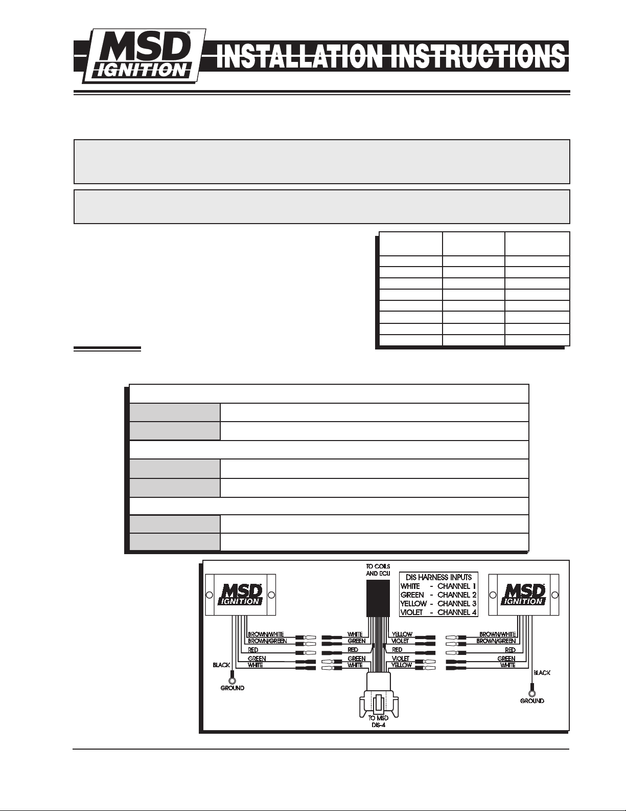
WIRING
The Adapter has six wires that need to be connected. The chart
FIRING DIS-4 BOX
ORDER A OR B
1 A 1
3 B 1
7 A 2
2 B 2
6 A 3
5 B 3
4 A 4
8 B 4
Figure 1
CHANNEL
shows each wire's application. Figure 2 shows how to wire the Adapter to the DIS ignitions.
WIRING
BLACK
RED
Connects to Ground.
Connects to 12 volt (Ignition).
INPUTS
BROWN/WHITE
BROWN/GREEN
Connects to the White wire going to the Coils and ECU.
Connects to the Green wire going to the Coils and ECU.
OUTPUTS
WHITE
GREEN
Connects to the White wire going to the MSD DIS Ignition.
Connects to the Green wire going to the MSD DIS Ignition.
Note: The pro c e dure
shown in Figure 2
will be performed
twice for each
DIS-4 Ignition PN
62152 (or H.O. PN
62153).
Figure 2 Installation to an MSD DIS-4 Ignition.
M S D I G N I T I O N • ww w. msd ig ni tio n. co m • ( 9 15 ) 8 57 -5 20 0 • FA X (9 15) 85 7 -3 34 4
Page 2
2 INS TA LLA TIO N INS TR UCT ION S
NOTES: This wiring diagram applies only
to SOHC applications. Please refer to
figure 5 and 6 for DOHC models.
This wiring diagram applies to cylinders
1, 7, 6 and 4. Please refer to Figure 4
for cylinders 3, 2, 5 and 8.
CYL. #1
CYL. #7
CYL. #6
CYL. #4
WHITE
BROWN/WHITE
RED
BROWN/ORANGE
GREEN
BROWN/GREEN
WHITE
BROWN/WHITE
RED
RED
BROWN/ORANGE
BROWN/ORANGE
GREEN
BROWN/GREEN
YELLOW
BROWN/YELLOW
RED
BROWN/ORANGE
VIOLET
BROWN/VIOLET
YELLOW
BROWN/YELLOW
RED
RED
BROWN/ORANGE
BROWN/ORANGE
VIOLET
BROWN/VIOLET
SOHC BOX A
NOTES: This wiring diagram applies
only to SOHC applications. Please refer
to figure 5 and 6 for DOHC models.
This wiring diagram applies to cylinders
3, 2, 5 and 8. Please refer to Figure 3
for cylinders 1, 7, 6 and 4.
CYL. #3
CYL. #2
CYL. #5
CYL. #8
WHITE
BROWN/WHITE
RED
BROWN/ORANGE
GREEN
BROWN/GREEN
WHITE
BROWN/WHITE
RED
RED
BROWN/ORANGE
BROWN/ORANGE
GREEN
BROWN/GREEN
YELLOW
BROWN/YELLOW
RED
BROWN/ORANGE
VIOLET
BROWN/VIOLET
YELLOW
BROWN/YELLOW
RED
RED
BROWN/ORANGE
BROWN/ORANGE
VIOLET
BROWN/VIOLET
SOHC BOX B
Figure 3
Figure 4
M S D I G N I T I O N • ww w. msd ig ni tio n. co m • ( 9 15 ) 8 57 -5 20 0 • FA X (9 15) 85 7 -3 34 4
Page 3

INS TA LLA TIO N INS TR UCT ION S 3
NOTES: This wiring diagram applies
only to DOHC applications. Please refer
to figure 3 and 4 for SOHC models.
This wiring diagram applies to cylinders
1, 7, 6 and 4. Please refer to Figure 6
for cylinders 3, 2, 5 and 8.
CYL. #1
CYL. #7
CYL. #6
CYL. #4
WHITE
BROWN/WHITE
RED
BROWN/ORANGE
GREEN
BROWN/GREEN
RED
BROWN/ORANGE
WHITE
GREEN
BROWN/WHITE
BROWN/GREEN
RED
BROWN/ORANGE
YELLOW
BROWN/YELLOW
RED
BROWN/ORANGE
VIOLET
BROWN/VIOLET
RED
BROWN/ORANGE
YELLOW
VIOLET
BROWN/YELLOW
BROWN/VIOLET
RED
BROWN/ORANGE
DOHC BOX A
NOTES: This wiring diagram applies
only to DOHC applications. Please refer
to figure 3 and 4 for SOHC models.
This wiring diagram applies to cylinders
3, 2, 5 and 8. Please refer to Figure 5
for cylinders 1, 7, 6 and 4.
CYL. #3
CYL. #2
CYL. #5
CYL. #8
WHITE
BROWN/WHITE
RED
BROWN/ORANGE
GREEN
BROWN/GREEN
RED
BROWN/ORANGE
WHITE
GREEN
BROWN/WHITE
BROWN/GREEN
RED
BROWN/ORANGE
YELLOW
BROWN/YELLOW
RED
BROWN/ORANGE
VIOLET
BROWN/VIOLET
RED
BROWN/ORANGE
YELLOW
VIOLET
BROWN/YELLOW
BROWN/VIOLET
RED
BROWN/ORANGE
DOHC BOX B
Figure 5
Figure 6
M S D I G N I T I O N • ww w. msd ig ni tio n. co m • ( 9 15 ) 8 57 -5 20 0 • FA X (9 15) 85 7 -3 34 4
Page 4

4 INSTALLATION INSTRUCTIONS
FRONT OF VEHICLE (RWD)
NOTE: COIL-ON-PLUG IGNITION
FORD MODULAR FIRING ORDER
1-3-7-2-6-5-4-8
1 2 3 4
5 6 7 8
4 INSTALLATION INSTRUCTIONS
Figure 7 Cylinder Identification.
Service
In case of malfunction, this MSD component will be repaired free of charge according to the terms of the warranty.
When returning MSD components for warranty service, Proof of Purchase must be supplied for verification. After
the warranty period has expired, repair service is based on a minimum and maximum fee.
All returns must have a Return Material Authorization (RMA) number issued to them before
being returned. To obtain an RMA number please contact MSD Customer Service at 1 (888) MSD-7859 or
visit our website at www.msdignition.com/rma to automatically obtain a number and shipping information.
When returning the unit for repair, leave all wires at the length in which you have them installed. Be sure to include
a detailed account of any problems experienced, and what components and accessories are installed on the vehicle.
The repaired unit will be returned as soon as possible using Ground shipping methods (ground shipping is covered
by warranty). For more information, call MSD Ignition at (915) 855-7123. MSD technicians are available from 7:00
a.m. to 6:00 p.m. Monday - Friday (mountain time).
Limited Warranty
M
SD IGNITION warrants this product to be free from defects in material and workmanship under its intended normal
use*, when properly installed and purchased from an authorized MSD dealer, for a period of one year from the date
of the original purchase. This warranty is void for any products purchased through auction websites. If found to be
defective as mentioned above, it will be repaired or replaced at the option of MSD Ignition. Any item that is covered
under this warranty will be returned free of charge using Ground shipping methods.
This shall constitute the sole remedy of the purchaser and the sole liability of MSD Ignition. To the extent permitted
by law, the foregoing is exclusive and in lieu of all other warranties or representation whether expressed or implied,
including any implied warranty of merchantability or fitness. In no event shall MSD Ignition or its suppliers be liable
for special or consequential damages.
*Intended normal use means that this item is being used as was originally intended and for the original application
as sold by MSD Ignition. Any modifications to this item or if it is used on an application other than what MSD Ignition
markets the product, the warranty will be void. It is the sole responsibility of the customer to determine that this item
will work for the application they are intending. MSD Ignition will accept no liability for custom applications.
M S D I G N I T I O N • ww w. msd ig ni tio n. co m • ( 9 15 ) 8 57 -5 20 0 • FA X (9 15) 85 7 -3 34 4
© 2007 Autotronic Controls Corporation
FRM28554 Revised 01/09 Printed in U.S.A.
 Loading...