

Page 1
Module 2 This is the default module. It is active when no voltage is present
on the other wires.
Active when 12 volts are applied to the Red Wire.
Active when 12 volts are applied to the Blue Wire. (3-Step Only)
Module 1
Note: If 12 volts are applied to the Red and Blue wires at the same time, Module 3
will be active.
Module 3
ACTIVATION WIRES
SWITCH OR
MICRO SWITCH
PN 8820
TO GROUND
TO 12V
RED
BLACK
TO MODULE SOCKET
TO LINE LOCK
OR TRANS-BRAKE
SOLENOID
MODULE SELECTOR
STEP
MODULE 2 MODULE 1
PN 8739
AUTOTRONIC CONTROLS CORPORATION
1490 HENRY BRENNAN DR, EL PASO, TX 79936
TM
MSD Module Selectors
Two Step, PN 8739
Three Step, PN 8737
ONLINE PRODUCT REGISTRATION: Register your MSD product online and you’ll be entered
in our monthly 8.5mm Super Conductor Spark Plug Wire give-away! Registering your product
will help if there is ever a warranty issue with your product and helps the MSD R&D team create
new products that you ask for! Go to www.msdignition.com/registration.
Parts Included:
1 - Module Selector
1 - Parts Bag, Wiring Terminals
4 - Mounting Screws
Note: Do NOT use solid core spark plug wires with any MSD component.
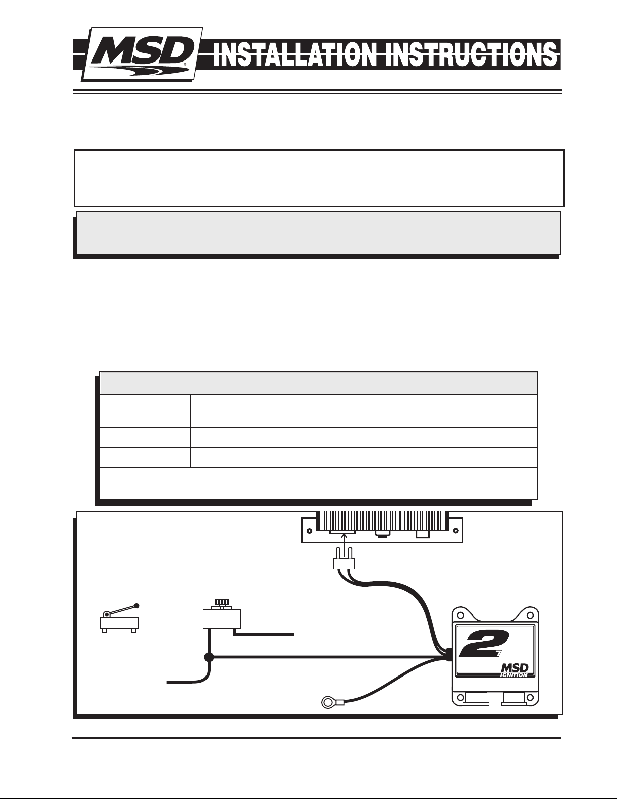
The MSD Module Selectors provide the ability to switch between two or three different rpm or degree
modules. The different modules are activated when 12 volts are applied to the corresponding activation wire. The Selectors work with either a Soft Touch Rev Control or any MSD Timing Control that
uses plug-in modules.
•The 2-Step Module Selector switches between two modules.
•The 3-Step Module Selector switches between three modules.
M S D • W W W . M S D P E R F O R M A N C E . C O M • ( 9 1 5 ) 8 5 7 - 5 2 0 0 • F A X ( 9 1 5 ) 85 7 - 3 3 4 4
Figure 1 Basic Two Step Module Selector Installation.
Page 2
2 INSTALLATION INSTRUCTIONS
T
A
C
H
C+
C-
IGN
PTS
M+
M-
GROUND
RPM
TO GROUND
TO 12V
MODULE 2 - ACTIVE WITH NO VOLTAGE.
MODULE 1 - ACTIVE WITH 12 VOLTS ON RED WIRE.
MODULE 3 - ACTIVE WITH 12 VOLTS ON BLUE WIRE. THIS
MODULE WILL ALSO BE ACTIVE IF 12 VOLTS
ARE SUPPLIED TO THE RED AND BLUE WIRES.
TO 12V
CLUTCH SWITCH
MSD MICRO SWITCH
PN 8820
BLUE
RED
BLACK
TO LINE LOCK
OR TRANS-BRAKE
SOLENOID
MODULE 2 MODULE 1
PN 8737
MODULE SELECTOR
3
MODULE 3
AUTOTRONIC CONTROLS CORPORATION
1490 HENRY BRENNAN DR, EL PASO, TX 79936
TM
BLACK
TO
GROUND
RELAY
PN 8961
RED
JUMPER
(+) 12V
CLUTCH
SWITCH
LINE LOCK
SOLENOID
REV LIMITER
(+) 12V
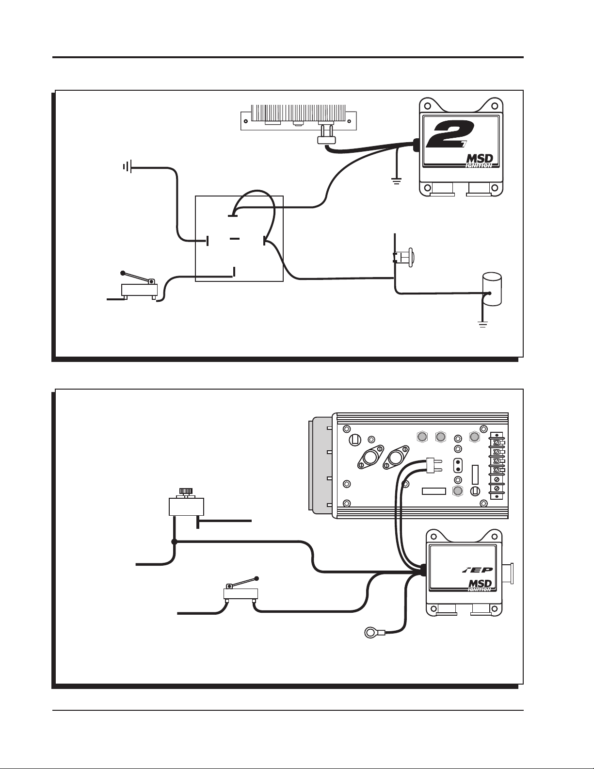
IF YOUR APPLICATION REQUIRES USING THE CLUTCH FOR EVERY SHIFT,
THIS DIAGRAM WILL PROVIDE A REV LIMIT ON THE LAUNCH ONLY AND
HOLD THE LINE LOCK ON UNTIL THE CLUTCH PEDAL IS RELEASED.
MOMENTARY
PUSH BUTTON
SWITCH
TO
GROUND
TO
GROUND
MODULE SELECTOR
STEP
MODULE 2 MODULE 1
PN 8739
AUTOTRONIC CONTROLS CORPORATION
1490 HENRY BRENNAN DR, EL PASO, TX 79936
TM
87A
87
NO
NC
C
86
85
30
Figure 2 Wiring a Two Step to a Latching Relay.
M S D • W W W . M S D P E R F O R M A N C E . C O M • ( 9 1 5 ) 8 5 7 - 5 2 0 0 • F A X ( 9 1 5 ) 85 7 - 3 3 4 4
Figure 3 Basic Three Step Installation.
Page 3

INSTALLATION INSTRUCTIONS 3
TACH OUTPUT
MAGNETIC
PICKUP
(NOT USED)
WHITE WIRE
TO POINTS OR
AMPLIFIER
IF USED
TO MAGNETIC
PICKUP
TRIGGER
IF USED
YELLOW
BLACK
(NOT USED)
WHITE
RED
GRAY
GRAY
RED
BLUE
SWITCH +12V TO ACTIVATE
SECOND RETARD
SWITCH +12V TO ACTIVATE
THIRD RETARD
FIRST RETARD
IGNITION KEY
+12 VOLTS
WHEN GRAY WIRE
IS GROUND THERE
IS NO RETARD, OPEN
SWITCH TO RETARD.
BLACK
TO GROUND
WHITE
TIMING COMPUTER
PN 8980
PN 8737
BLACK
FIRST
RETARD
THIRD
RETARD
SECOND
RETARD
ORANGE
RED
BLACK
COIL
IGNITION
TM
Multiple
Spark
Discharge
MODULE 2 MODULE 1
PN 8737
MODULE SELECTOR
3
M
O
D
U
LE
3
AUTOTRONIC CONTROLS CORPORATION
1490 HENRY BRENNAN DR, EL PASO, TX 79936
TM
+
HEAVY RED
HEAVY BLACK
TO BATTERY
TO BATTERY
+
RED
BLUE
SWITCH +12V TO ACTIVATE
SECOND SHIFT POINT
SWITCH +12V TO ACTIVATE
THIRD SHIFT POINT
PN 8737
BLACK
FIRST
SHIFT POINT
THIRD
SHIFT POINT
SECOND
SHIFT POINT
MODULE 2 MODULE 1
PN 8737
MODULE SELECTOR
3
MODULE 3
AUTOTRONIC CONTROLS CORPORATION
1490 HENRY BRENNAN DR, EL PASO, TX 79936
TM
AUTOTRONIC CONTROLS CORPORATION
PART NO.
SERIAL NO..
Figure 4 Wiring a Three Step to a Timing Control for Multiple Retards.
SHIFT LIGHT
BLACK
RED
TO SWITCHED
12 VOLTS
GREEN
TACH OUTPUT
Figure 5 Wiring a Three Step to a Shift Light for Multiple Shift Points.
TO GROUND
TO
M S D • W W W . M S D P E R F O R M A N C E . C O M • ( 9 1 5 ) 8 5 7 - 5 2 0 0 • F A X ( 9 1 5 ) 85 7 - 3 3 4 4
Page 4

TECH NOTES
_________________________________________________________________________________________________________________________
_________________________________________________________________________________________________________________________
_________________________________________________________________________________________________________________________
_________________________________________________________________________________________________________________________
_________________________________________________________________________________________________________________________
_________________________________________________________________________________________________________________________
_________________________________________________________________________________________________________________________
_________________________________________________________________________________________________________________________
_________________________________________________________________________________________________________________________
_________________________________________________________________________________________________________________________
_________________________________________________________________________________________________________________________
_________________________________________________________________________________________________________________________
_________________________________________________________________________________________________________________________
_________________________________________________________________________________________________________________________
_________________________________________________________________________________________________________________________
_________________________________________________________________________________________________________________________
Service
In case of malfunction, this MSD component will be repaired free of charge according to the terms of the warranty.
When returning MSD components for warranty service, Proof of Purchase must be supplied for verification. After
the warranty period has expired, repair service is based on a minimum and maximum fee.
All returns must have a Return Material Authorization (RMA) number issued to them before
being returned. To obtain an RMA number please contact MSD Customer Service at 1 (888) MSD-7859 or visit
our website at www.msdperformance.com/rma to automatically obtain a number and shipping information.
When returning the unit for repair, leave all wires at the length in which you have them installed. Be sure to include
a detailed account of any problems experienced, and what components and accessories are installed on the vehicle.
The repaired unit will be returned as soon as possible using Ground shipping methods (ground shipping is covered
by warranty). For more information, call MSD at (915) 855-7123. MSD technicians are available from 7:00 a.m. to
5:00 p.m. Monday - Friday (mountain time).
Limited Warranty
M
SD warrants this product to be free from defects in material and workmanship under its intended normal use*,
when properly installed and purchased from an authorized MSD dealer, for a period of one year from the date of
the original purchase. This warranty is void for any products purchased through auction websites. If found to be
defective as mentioned above, it will be repaired or replaced at the option of MSD. Any item that is covered under
this warranty will be returned free of charge using Ground shipping methods.
This shall constitute the sole remedy of the purchaser and the sole liability of MSD. To the extent permitted by
law, the foregoing is exclusive and in lieu of all other warranties or representation whether expressed or implied,
including any implied warranty of merchantability or fitness. In no event shall MSD or its suppliers be liable for special
or consequential damages.
*Intended normal use means that this item is being used as was originally intended and for the original application
as sold by MSD. Any modifications to this item or if it is used on an application other than what MSD markets the
product, the warranty will be void. It is the sole responsibility of the customer to determine that this item will work for
the application they are intending. MSD will accept no liability for custom applications.
M S D • W W W . M S D P E R F O R M A N C E . C O M • ( 9 1 5 ) 8 5 7 - 5 2 0 0 • F A X ( 9 1 5 ) 85 7 - 3 3 4 4
© 2012 Autotr onic Contr ols Corporation
FRM28948 Revised 01/12 Printed in U.S.A.
 Loading...