

Page 1
MSD 2-Step Launch Control
for Ford 4.6L/5.4L Mod Motors '99-On
PN 8734
ONLINE PRODUCT REGISTRATION: Register your MSD product online and you’ll be entered
in our monthly 8.5mm Super Conductor Spark Plug Wire give-away! Registering your product
will help if there is ever a warranty issue with your product and helps the MSD R&D team create
new products that you ask for! Go to www.msdperformance.com/registration.
Parts Included:
1 - 2-Step Launch Control
1 - Harness
Note: The 2-Step Launch Control is a low-rpm limiter that will not provide nor modify any overrev
protection. The stock high rpm rev limiter will still be active.
The MSD 2-Step Launch Control is designed for Ford Modular Enhgines with Coil-on-Plug ignitions. The
2-Step Control will provide consistent launches and quick 60-foot times. RPM adjustments are made via
two rotary switches located on the harness side of the unit. The adjustment range is from 1,000 - 10,900
rpm, in 100 and 1000 rpm increments, an LED will illujminate when the launch rev limit is active.
Note: It is recommended to have the service manual for your vehicle.
Note: The engine rpm must drop more than one third of the set launch limit in order to activate. For
example, if the launch limit is set at 3,000 rpm, the engine speed must drop below 2,000 rpm
in order for the launch limit to become active (one third of 3,000 rpm is a 1,000 rpm drop).
Caution: Keeping the engine on a lower rpm limit may cause the Check Engine light to come on
and could potentially damage the catalytic converter.
Parts Bag:
1 - Tap
3 - Mounting Screws
MOUNTING
The 2-Step Control can be mounted in any position but keep in mind to mount it so the rotary dials
are accessible for adjustments. Hardware is supplied for mounting. Before mounting the unit, confirm
that the wiring harnesses reach their connections.
WIRING
8-WIRE CONNECTOR
Tan (8) Signal Connections.
8-WIRE CONNECTOR
Red 12 volt Connection through this single Red wire.
3-WIRE CONNECTOR
Black Connects to a good engine round or the negative battery terminal.
Blue Activation Wire. When grounded, the launch feature will be active.
White/Blue Activation Wire. When switched to 12 volts, the launch feature will be active.
M S D • W W W . M S D P E R F O R M A N C E . CO M • ( 9 1 5 ) 8 5 7 - 5 2 0 0 • FA X ( 9 1 5 ) 8 5 7 - 3 3 4 4
Page 2
2 INSTALLATION INSTRUCTIONS
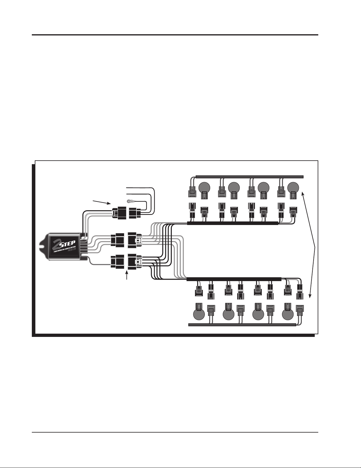
1. Connect the 3-pin harness to the 2-step and connect the Black wire to the good engine or chassis
ground.
2. Disconnect the 2-pin connectors from each of the eight ignition coils.
3. Connect all eight of the 2-pin male connectors from the MSD harness into the factory coil connectors.
4. Plug the 8-pin connector with the single Red wire from the 2-Step to the connector with Black wires.
5. Turn the key to the On position - do NOT start the engine. Look at the LED on the 2-Step:
LED On - This confirms that the wiring is correct and you can move to step 6 (Figure 1).
LED Off - The wiring is different for this application and needs to be changed. Turn the key Off, plug the
8-pin connector with the eight Gray wires into the connector with the single Red wire (Figure 2).
6. Connect the 8-pin harness with the tan wires to the remaining connector on the harness.
7. Connect all eight of the female 2-pin connectors from the MSD harness into the factory coils.
ACTIVATION
WIRES
WHITE BLUE
BLUE
STEP 4
ACTIVATES
WITH 12 VOLTS
OR GROUND
GROUND
TAN
RED
GRAY
STEP 2
BLACK
STEP 3
Figure 1 Wiring the 2-Step Launch Control.
M S D • W W W . M S D P E R F O R M A N C E . C O M • ( 9 1 5 ) 8 5 7 - 5 2 0 0 • F A X ( 9 1 5 ) 8 5 7 - 3 3 4 4
Page 3

INSTALLATION INSTRUCTIONS 3
ACTIVATION
ACTIVATES
WITH 12 VOLTS
OR GROUND
GROUND
WHITE BLUE
BLUE
WIRES
TAN
RED
BLACK
GRAY
NOTE: IF THE LED DOESN'T TURN ON, AS
DETAILED IN STEP 5, FOLLOW THIS
DIAGRAM.
Figure 2 Alternate Wiring.
CONNECT THE ACTIVATION WIRE
The launch rpm limit can be activated through a ground or a 12 volt source.
Ground: Switch the Blue wire to ground to activate the launch limit.
12 volts: Connect the White/Blue wire to 12 volts to activate the launch limit.
OR
NOTE: DO NOT USE THE BLUE AND BLUE/WHITE
WIRES AT THE SAME TIME.
BLUE - ACTIVATED WHEN GROUND
WHITE/BLUE - ACTIVATED W/12 VOLTS
Figure 3 Wiring the Launch Activation Wire.
CONFIRM INSTALLATION
With the power On, engine running, activate the clutch or On/Off switch. If connected correct, the LED will
illuminate when the clutch is activated. To verify the rpm, set the limit at a lower rpm, such as 3,000, and
test the system.
If the engine has trouble starting or running. check the following:
• Ground or switched 12 volts connection
• Coil connections
• The two 8-pin connectors may be in the wrong position and should be swapped and tested again.
M S D • W W W . M S D P E R F O R M A N C E . C O M • ( 9 1 5 ) 8 5 7 - 5 2 0 0 • F A X ( 9 1 5 ) 8 5 7 - 3 3 4 4
Page 4

TECH NOTES
_________________________________________________________________________________________________________________________
_________________________________________________________________________________________________________________________
_________________________________________________________________________________________________________________________
_________________________________________________________________________________________________________________________
_________________________________________________________________________________________________________________________
_________________________________________________________________________________________________________________________
_________________________________________________________________________________________________________________________
_________________________________________________________________________________________________________________________
_________________________________________________________________________________________________________________________
_________________________________________________________________________________________________________________________
_________________________________________________________________________________________________________________________
_________________________________________________________________________________________________________________________
_________________________________________________________________________________________________________________________
_________________________________________________________________________________________________________________________
_________________________________________________________________________________________________________________________
_________________________________________________________________________________________________________________________
_________________________________________________________________________________________________________________________
_________________________________________________________________________________________________________________________
Service
In case of malfunction, this MSD component will be repaired free of charge according to the terms of the warranty.
When returning MSD components for warranty service, Proof of Purchase must be supplied for verification. After
the warranty period has expired, repair service is based on a minimum and maximum fee.
All returns must have a Return Material Authorization (RMA) number issued to them before
being returned. To obtain an RMA number please contact MSD Customer Service at 1 (888) MSD-7859 or visit
our website at www.msdperformance.com/rma to automatically obtain a number and shipping information.
When returning the unit for repair, leave all wires at the length in which you have them installed. Be sure to include
a detailed account of any problems experienced, and what components and accessories are installed on the vehicle.
The repaired unit will be returned as soon as possible using Ground shipping methods (ground shipping is covered
by warranty). For more information, call MSD at (915) 855-7123. MSD technicians are available from 7:00 a.m. to
5:00 p.m. Monday - Friday (mountain time).
Limited Warranty
M
SD warrants this product to be free from defects in material and workmanship under its intended normal use*,
when properly installed and purchased from an authorized MSD dealer, for a period of one year from the date of
the original purchase. This warranty is void for any products purchased through auction websites. If found to be
defective as mentioned above, it will be repaired or replaced at the option of MSD. Any item that is covered under
this warranty will be returned free of charge using Ground shipping methods.
This shall constitute the sole remedy of the purchaser and the sole liability of MSD. To the extent permitted by
law, the foregoing is exclusive and in lieu of all other warranties or representation whether expressed or implied,
including any implied warranty of merchantability or fitness. In no event shall MSD or its suppliers be liable for special
or consequential damages.
*Intended normal use means that this item is being used as was originally intended and for the original application
as sold by MSD. Any modifications to this item or if it is used on an application other than what MSD markets the
product, the warranty will be void. It is the sole responsibility of the customer to determine that this item will work for
the application they are intending. MSD will accept no liability for custom applications.
M S D • W W W . M S D P E R F O R M A N C E . C O M • ( 9 1 5 ) 8 5 7 - 5 2 0 0 • F A X ( 9 1 5 ) 8 5 7 - 3 3 4 4
© 2012 Autotr onic Con trols Corporation
FRM29644 Revised 01/12 Printed in U.S.A.
 Loading...