

Page 1
Digital 2-Step
PN 8732
For the Digital 6AL Ignition Control, PN 6425
ONLINE PRODUCT REGISTRATION: Register your MSD product online and you’ll be entered
in our monthly 8.5mm Super Conductor Spark Plug Wire give-away! Registering your product
will help if there is ever a warranty issue with your product and helps the MSD R&D team create
new products that you ask for! Go to www.msdignition.com/registration.
Parts Included:
1 – Control
4 – Mounting Screws
WARNING: During installation, disconnect the battery cables. When disconnecting the
battery, always remove the negative cable first and install it last.
Note: Must be used with an MSD Digital 6AL Ignition, PN 6425.
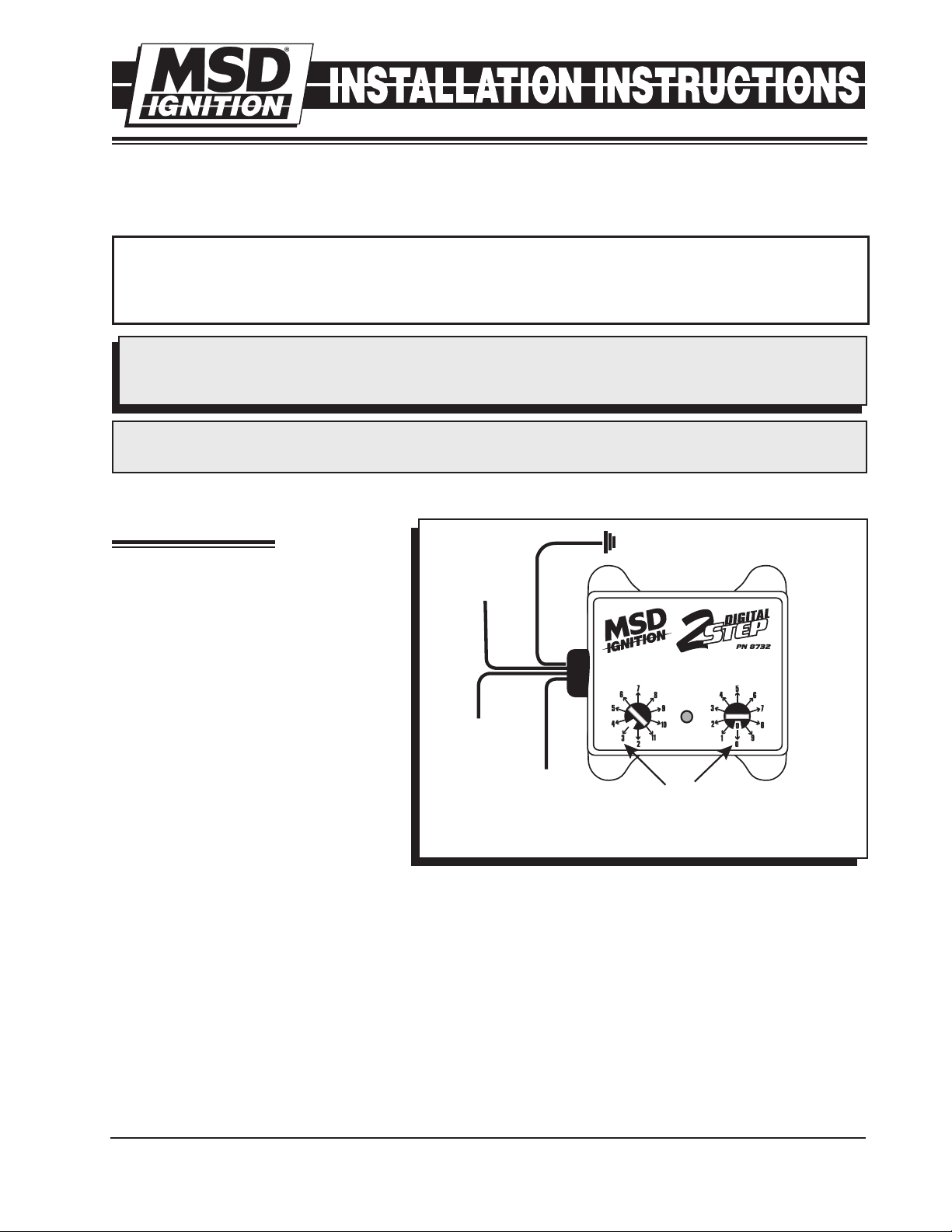
OPERATION
The Digital 2-Step Control is designed
specifically for the MSD Digital 6AL
TO
SWITCHED
12V
BLACK
TO GROUND
Ignition Control, PN 6425. It provides
the ability to set an rpm limit to be used
during the launch of the vehicle through
a switch or tied into a line-lock device
or trans-brake.
There is a Blue wire coming out of the
2-Step, that controls when the launch
rpm limit is activated. When this wire
is connected to 12 volts, the 2-Step is
activated. When released, the rpm limit
that is set in the Digital 6AL Ignition is
active. This wire can be tied into a trans-
RED
BLUE
ACTIVATE THE
2-STEP WITH
12 VOLTS
GRAY
TACH WIRE
ON MSD 6AL
TO
PN 6425
X1000 X100
ALWAYS SET THE RPM VALUE
WITH THE PRINTED NUMBER ON
THE HOUSING. THIS FIGURE
SHOWS A SETTING OF 3000 RPM.
brake circuit, a clutch switch or simply
a stand alone switch.
Figure 1
RPM LIMIT
The rpm limit is set with the two rotary dials, in 100 rpm increments. The limit can be programmed
from 2,000 rpm to 11,800 rpm. (The position for 11,900 is reserved for use with MSD's Power Grid
ignition system.)
LED
There is a useful LED built into the Digital 2-Step. This LED will illuminate when 12 volts are applied to
the Blue wire and the low rpm limit of the 2-Step is active. When 12 volts are removed from the Blue
wire the 2-Step rev limit and the LED will turn off.
3-STEP
If you prefer to have three different rev limits, a second PN 8732 could be used to provide a third rev
limit, such as for use during the burnout.
M S D I G N I T I O N • WW W. MSD IG NI TIO N. CO M • (9 15 ) 8 57 -52 00 • FA X ( 91 5) 8 57 -3 34 4
Page 2
2 INSTALLATION INSTRUCTIONS
MOUNTING
It is suggested to mount the unit within easy reach for adjustments. The Control can be mounted
under the hood but should be away from direct engine heat sources. Make sure the wiring reaches the
connections and mark the mounting holes. Use an 1/8” bit to drill mounting holes and mount the unit.
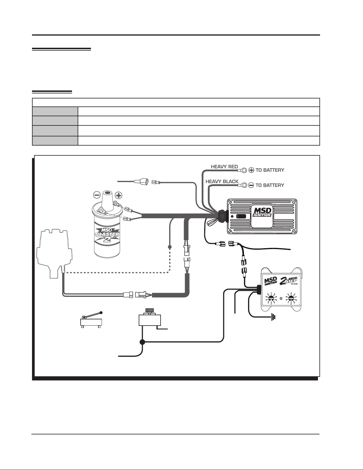
WIRING
WIRING
Red Power. Connect to a switched 12 volts.
Black Ground. Connect to ground.
Blue Launch RPM Activation wire. When connected to 12 volts the launch rpm value is active.
Gray Tach Signal. Connect to the Gray Tach Output wire of the MSD PN 6425.
12 VOLTS IGNITION KEY
DISTRIBUTOR
POINTS/AMPLIFIER
MAGNETIC PICKUP
MICRO SWITCH
PN 8820
OR
SWITCH OR
ORANGE
BLACK
WHITE
RED
VIOLET
TO 12V
GREEN
BLUE
GRAY
REV
LIMITER
GRAY
RED
12 VOLTS
DIGITAL 6AL
BLACK
X1000
TO GROUND
TACH
OUTPUT
X100
TO LINE LOCK
OR TRANS-BRAKE
SOLENOID
Figure 2 Wiring the Control with an MSD Digital 6AL Ignition Control.
M S D I G N I T I O N • WW W. MSD IG NI TIO N. CO M • (9 15 ) 8 57 -52 00 • FA X ( 91 5) 8 57 -3 34 4
Page 3

INSTALLATION INSTRUCTIONS 3
TO MSD
DIGITAL 6AL
TO
GROUND
87
87A
CLUTCH
SWITCH
(+) 12V
IF YOUR APPLICATION REQUIRES USING THE CLUTCH FOR EVERY SHIFT,
THIS DIAGRAM WILL PROVIDE A REV LIMIT ON THE LAUNCH ONLY AND
HOLD THE LINE LOCK ON UNTIL THE CLUTCH PEDAL IS RELEASED.
86
30
RELAY
PN 8961
GRAY
JUMPER
NO
NC
C
GRAY
BLUE
85
12 VOLTS
RED
BLACK
GROUND
TO
TO
TACH
OUTPUT
X1000 X100
TO 12 VOLTS
MOMENTARY
PUSH BUTTON
SWITCH
LINE LOCK
SOLENOID
GROUND
TO
Figure 3 Wiring the Digital 2-Step to a Latching Relay.
WIRE TAP INSTALLATION
1. Insert male end cup into wire to be spliced.
3. Hand tighten barrel into male end cup.
3. Strip wire approximately 3/8” (10mm).
4. Insert wire into male end exposing only bare
wire.
5. Hand tighten male end to barrel.
MALE
END
BARREL
3/8”
(10mm)
WIRE TO BE
SPLICED
MALE
END
CUP
Figure 4 Wire Tap.
M S D I G N I T I O N • WW W. MSD IG NI TIO N. CO M • (9 15 ) 8 57 -52 00 • FA X ( 91 5) 8 57 -3 34 4
Page 4

4 INSTALLATION INSTRUCTIONS
TECH NOTES
_________________________________________________________________________________________________________________________
_________________________________________________________________________________________________________________________
_________________________________________________________________________________________________________________________
_________________________________________________________________________________________________________________________
_________________________________________________________________________________________________________________________
_________________________________________________________________________________________________________________________
_________________________________________________________________________________________________________________________
_________________________________________________________________________________________________________________________
_________________________________________________________________________________________________________________________
_________________________________________________________________________________________________________________________
_________________________________________________________________________________________________________________________
_________________________________________________________________________________________________________________________
_________________________________________________________________________________________________________________________
_________________________________________________________________________________________________________________________
_________________________________________________________________________________________________________________________
Service
In case of malfunction, this MSD component will be repaired free of charge according to the terms of the warranty.
When returning MSD components for warranty service, Proof of Purchase must be supplied for verification. After
the warranty period has expired, repair service is based on a minimum and maximum fee.
All returns must have a Return Material Authorization (RMA) number issued to them before
being returned. To obtain an RMA number please contact MSD Customer Service at 1 (888) MSD-7859 or
visit our website at www.msdignition.com/rma to automatically obtain a number and shipping information.
When returning the unit for repair, leave all wires at the length in which you have them installed. Be sure to include
a detailed account of any problems experienced, and what components and accessories are installed on the vehicle.
The repaired unit will be returned as soon as possible using Ground shipping methods (ground shipping is covered
by warranty). For more information, call MSD Ignition at (915) 855-7123. MSD technicians are available from 7:00
a.m. to 5:00 p.m. Monday - Friday (mountain time).
Limited Warranty
M
SD IGNITION warrants this product to be free from defects in material and workmanship under its intended normal
use*, when properly installed and purchased from an authorized MSD dealer, for a period of one year from the date
of the original purchase. This warranty is void for any products purchased through auction websites. If found to be
defective as mentioned above, it will be repaired or replaced at the option of MSD Ignition. Any item that is covered
under this warranty will be returned free of charge using Ground shipping methods.
This shall constitute the sole remedy of the purchaser and the sole liability of MSD Ignition. To the extent permitted
by law, the foregoing is exclusive and in lieu of all other warranties or representation whether expressed or implied,
including any implied warranty of merchantability or fitness. In no event shall MSD Ignition or its suppliers be liable
for special or consequential damages.
*Intended normal use means that this item is being used as was originally intended and for the original application
as sold by MSD Ignition. Any modifications to this item or if it is used on an application other than what MSD Ignition
markets the product, the warranty will be void. It is the sole responsibility of the customer to determine that this item
will work for the application they are intending. MSD Ignition will accept no liability for custom applications.
M S D I G N I T I O N • WW W. MSD IG NI TIO N. CO M • (9 15 ) 8 57 -52 00 • FA X ( 91 5) 8 57 -3 34 4
© 2010 Autotronic Controls Corporat ion
FRM30243 Revised 01/11 Printed in U.S.A.
 Loading...