

Adjustable Timing Control
PN 8680
ONLINE PRODUCT REGISTRATION: Register your MSD product online and you’ll be entered in our
monthly 8.5mm Super Conductor Spark Plug Wire give-away! Registering your product will help if there
is ever a warranty issue with your product and helps the MSD R&D team create new products that you
ask for! Go to www.msdperformance.com/registration.
IMPORTANT: Read the instructions before attempting installation.
Parts Included:
1 - Timing Control, PN 8680 1 - Control Knob
1 - 3/8" Bushing 1 - 2-Pin Weathertight Connector
4 - Self Tapping Screws
WARNING: During installation, disconnect the battery cables. When disconnecting the battery,
always remove the Negative cable first and install it last.
Note: The MSD PN 8680 Timing Control must be used with an MSD Ignition Control. It is recommended
to install the MSD Ignition first.
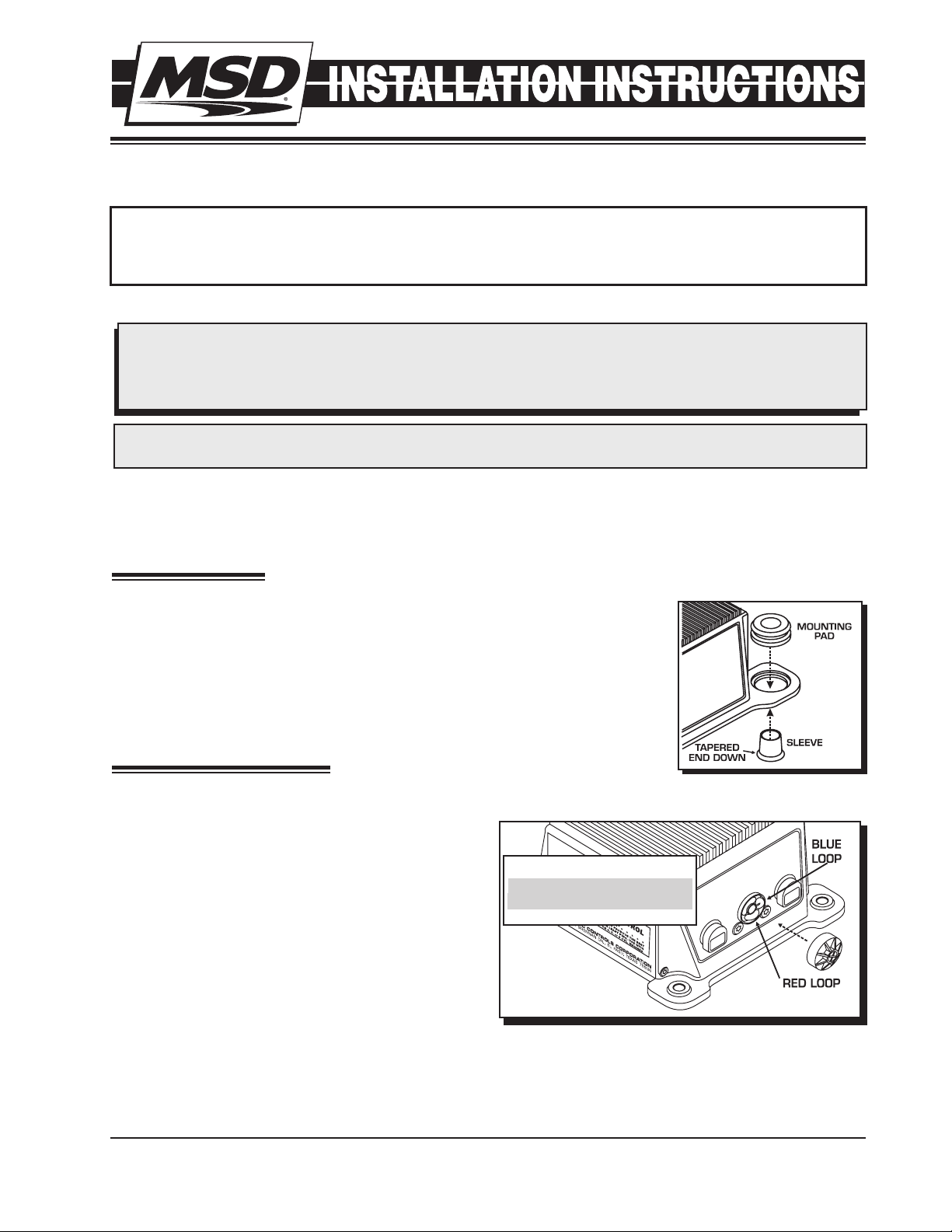
MOUNTING
The Timing Computer may be mounted in the engine compartment as long
as it is away from direct engine heat sources. Make sure all of the wires reach
their connections before mounting the unit. Use the Control as a template
and mark the mounting holes. Remove the unit and drill the mounting holes
using an 1/8" drill bit. Four self tapping screws are supplied to mount the unit.
Note: Before mounting the unit, install the supplied grommets and sleeves
as shown in Figure 1.
PROGRAMMING
The Timing Control is programmed for 8-cylinder. If installing the PN 8680 on
a 4 or 6-cylinder, the Control must be programmed.
Locate the Cylinder Select cover on the side of the
unit and remove the single Phillips screw (Figure 2).
CYLINDERS CUT LOOPS
Number of Cylinders: The Red loop and the Blue
loop are responsible for cylinder programming. The
chart in Figure 2 shows which loop(s) to cut.
8 NONE
6 RED
4 RED AND BLUE
Note: After cutting a loop, position the wire ends
away from each other so they cannot make
contact.
Figure 2 Selecting the Number of Cylinders.
M S D • W W W . M S D P E R F O R M A N C E . C O M • ( 9 1 5 ) 8 5 7 - 5 2 0 0 • F A X ( 9 1 5 ) 8 5 7 - 3 3 4 4
Figure 1 Installing the
Vibration Mounts.
2 INSTALLATION INSTRUCTIONS
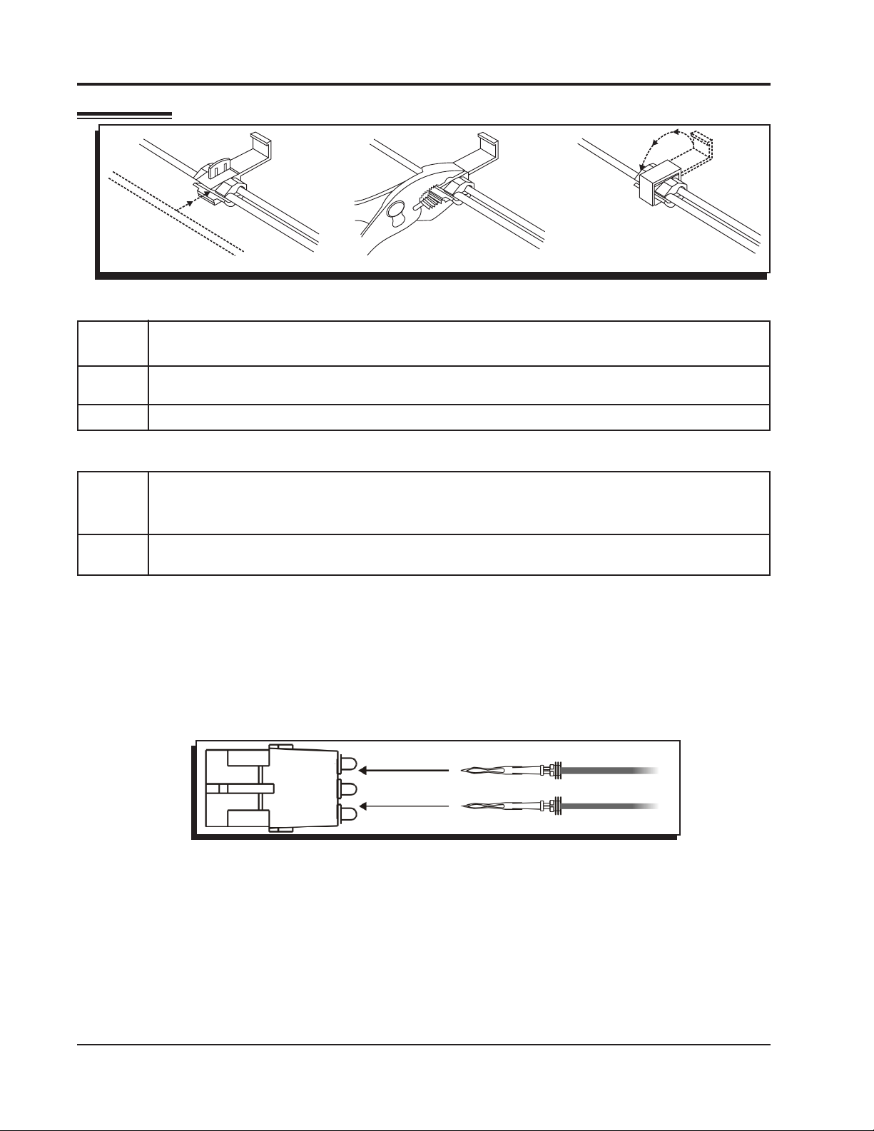
WIRING
Figure 3 How to use the Supplied Wire Splice Device.
WIRE FUNCTIONS
Yellow This is the trigger output wire. It connects to the White wire of an MSD 6 Series Ignition or
“Points” terminal of a 7 Series Ignition.
Red This wire is responsible for turning the Timing Control on and off. It connects to switched
12 volt source. It can be spliced into the small red wire of the MSD.
Black This is the ground wire and must be connected to a good engine or chassis ground.
TRIGGER WIRES
Violet These wires connect to the magnetic pickup of the distributor or crank trigger. The
Green Violet is positive (+) and the Green wire is negative (-). When this connector is used
the White wire is not.
White This is the trigger input wire for breaker points or ignition amplifier. When this wire is used,
the magnetic pickup wires (violet and green) are not.
Control Knob
The Black and Gray wires with the 2-Pin Weathertight connector are the Control Knob wires. After the
Timing Control is mounted, the Harness should be routed to the unit. The Control Knob should be
mounted within easy reach of the driver. Before mounting the Control Knob, make sure the wiring harness
reaches the unit.
If the harness must be routed through the firewall, drill a 3/8" hole and use the supplied grommet to route
the wires through. Install the supplied 2-Pin Weathertight connector to the wires after all of the routing is
finished (Figure 4). The position of the wires in the connector is not important.
Figure 4 Installing the Weathertight Connector.
Operating the Control
After installation, it is recommended to check the timing. Before starting the vehicle, turn the Control Knob
to the full 15° mark. This is the stock timing setting. As the Knob is turned counterclockwise, the timing
retards. As detonation occurs, slowy retard the timing until the “pinging” noise is not audible. Adjust the
timing as driving conditions change.
Resetting the Timing
It is possible to set the Timing Control up to where you can retard and advance the timing 7.5° each.
To do this, position the Control Knob in the center (approximately 7.5°) then reset the timing to factory
specifications.
M S D • W W W . M S D P E R F O R M A N C E . C O M • ( 9 1 5 ) 8 5 7 - 5 2 0 0 • F A X ( 9 1 5 ) 8 5 7 - 3 3 4 4
BLACK
BLACK
WHITE
WHITE
RED
RED
YELLOW
FROM IGNITION
KEY
INDICATES CONNECTION USING
WIRE SPLICE DEVICE
TO GROUND
ORANGE
MAG PICKUP
NOT USED
NOT USED
TIMING
CONTROL UNIT
TACH
OUTPUT
IGNITION
Multiple
Spark
Discharge
MSD
COIL
C+
C-
POINTS
OR AMPLIFIER
DISTRIBUTOR
ORIGINAL
COIL WIRE
-
ORIGINAL COIL+ WIRE
HEAVY RED
HEAVY BLACK
TO BATTERY+
TO BATTERY-
A
D
V
A
N
C
E
TM
TIMING
CONTROL
R
MAG PICKUP
INSTALLATION INSTRUCTIONS 3
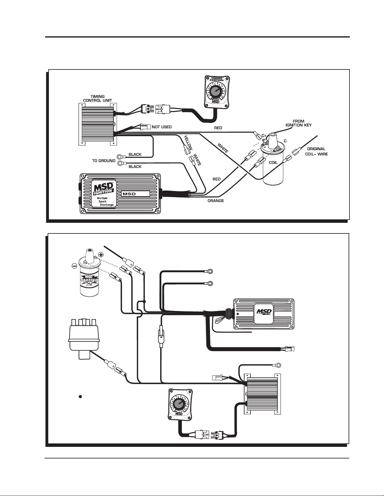
DIAGRAMS
The following wiring diagrams show common installations.
NOTE: The MSD 5 and Blaster Ignitions
are inductive designs and do not share
the same wiring as the 6-Series Ignitions.
Figure 5 Wiring to a Points or Amplifier Ignition with an MSD 5 or Blaster Ignition using the Points Trigger.
ORIGINAL COIL+ WIRE
FROM IGNITION
KEY
BLACK
ORANGE
HEAVY RED
HEAVY BLACK
RED
TO BATTERY+
TO BATTERY-
GRAY
DIGITAL 6A
TACH OUTPUT
POINTS
OR AMPLIFIER
DISTRIBUTOR
WHITE
GREEN (-)
ORIGINAL
COIL WIRE
-
RED
YELLOW
VIOLET (+)
MAG PICKUP
MAGNETIC PICKUP
BLACK
TO GROUND
(NOT USED)
NOT USED
WHITE
INDICATES CONNECTION USING
WIRE SPLICE DEVICE
TIMING
CONTROL
A
D
C
V
A
N
E
TM
TIMING
CONTROL UNIT
Figure 6 Wiring to Points or Amplifier Ignition with an MSD 6 Series.
M S D • W W W . M S D P E R F O R M A N C E . C O M • ( 9 1 5 ) 8 5 7 - 5 2 0 0 • F A X ( 9 1 5 ) 8 5 7 - 3 3 4 4

4 INSTALLATION INSTRUCTIONS
The PN 8680 can be installed with
other magnetic distributors. The
polarity of the pick-up wires must
be correctly wired to the MSD.
RED
ORANGE
WHITE
BLACK
VIOLET (+)
MAGNETIC PICKUP
GREEN (-)
(NOT USED)
Figure 6 Wiring to Magnetic Pickup Trigger with an MSD 6 Series.
CGND
B+
18” BLACK TO
ENGINE GROUND
YELLOW
GREEN (-)
VIOLET (+)
MAGNETIC PICKUP
(NOT USED)
DIGITAL 6A
GRAY
TACH OUTPUT
MAGNETIC PICKUP
(NOT USED)
GRAY
BLACK
TO GROUND
DIGITAL 6A
TACH OUTPUT
TIMING
CONTROL
A
D
E
C
V
A
N
TIMING
CONTROL UNIT
TM
Figure 7 Installation to a GM HEI with a 5 or 7-Pin Module (Points Trigger).
M S D • W W W . M S D P E R F O R M A N C E . C O M • ( 9 1 5 ) 8 5 7 - 5 2 0 0 • F A X ( 9 1 5 ) 8 5 7 - 3 3 4 4

INSTALLATION INSTRUCTIONS 5
CGND
B+
DIGITAL 6A
18” BLACK TO
ENGINE GROUND
RED
GREEN (-)
VIOLET (+)
TACH OUTPUT
GRAY
MAGNETIC PICKUP
(NOT USED)
WHITE
(NOT USED)
YELLOW WHITE
YELLOW
RED
Figure 8 Installation to a GM HEI with a 4-Pin Module (Magnetic Trigger).
Note: The PN 8876 and PN 8877 Harnesses install the same as the 8874 shown.
MAGNETIC PICKUP
BLACK
TO GROUND
(NOT USED)
TIMING
CONTROL
A
D
V
A
N
E
C
TM
GRAY
GREEN (-)
VIOLET (+)
DIGITAL 6A
TACH OUTPUT
MAGNETIC PICKUP
(NOT USED)
TIMING
CONTROL UNIT
Figure 9 Wiring with an MSD PN 8874, 8876 or 8877 Harness.
M S D • W W W . M S D P E R F O R M A N C E . C O M • ( 9 1 5 ) 8 5 7 - 5 2 0 0 • F A X ( 9 1 5 ) 8 5 7 - 3 3 4 4

6 INSTALLATION INSTRUCTIONS
Note: The MSD 6 and 7 Series Ignitions share the same wire colors.
ORANGE
BLACK
ORANGE
BLACK
Figure 10 Wiring to Points or Amplifier with an MSD 7 Series.
Figure 11 Wiring to Magnetic Pickup with an MSD 7 Series.
M S D • W W W . M S D P E R F O R M A N C E . C O M • ( 9 1 5 ) 8 5 7 - 5 2 0 0 • F A X ( 9 1 5 ) 8 5 7 - 3 3 4 4

INSTALLATION INSTRUCTIONS 7
DIGITAL 6A
TACH OUTPUT
GRAY
MAGNETIC PICKUP
(NOT USED)
TIMING
CONTROL UNIT
BLACK
TO GROUND
TIMING
CONTROL
A
D
E
C
V
A
N
TM
GREEN (-)
VIOLET (+)
MAGNETIC PICKUP
(NOT USED)
Figure 12 Wiring to a Mallory 3-Wire Distributor.
TACH OUTPUT
GRAY
MAGNETIC PICKUP
(NOT USED)
CONTROL UNIT
DIGITAL 6A
TIMING
GREEN (-)
VIOLET (+)
BLACK
TO GROUND
MAGNETIC PICKUP
(NOT USED)
TIMING
CONTROL
A
D
E
C
V
A
N
TM
Figure 13 Wiring to a Mallory Distributor w/ Mag Pickup.
M S D • W W W . M S D P E R F O R M A N C E . C O M • ( 9 1 5 ) 8 5 7 - 5 2 0 0 • F A X ( 9 1 5 ) 8 5 7 - 3 3 4 4

TECH NOTES
_________________________________________________________________________________________________________________________
_________________________________________________________________________________________________________________________
_________________________________________________________________________________________________________________________
_________________________________________________________________________________________________________________________
_________________________________________________________________________________________________________________________
_________________________________________________________________________________________________________________________
_________________________________________________________________________________________________________________________
_________________________________________________________________________________________________________________________
_________________________________________________________________________________________________________________________
_________________________________________________________________________________________________________________________
_________________________________________________________________________________________________________________________
_________________________________________________________________________________________________________________________
_________________________________________________________________________________________________________________________
_________________________________________________________________________________________________________________________
_________________________________________________________________________________________________________________________
_________________________________________________________________________________________________________________________
_________________________________________________________________________________________________________________________
_________________________________________________________________________________________________________________________
Service
In case of malfunction, this MSD component will be repaired free of charge according to the terms of the warranty.
When returning MSD components for warranty service, Proof of Purchase must be supplied for verification. After
the warranty period has expired, repair service is based on a minimum and maximum fee.
All returns must have a Return Material Authorization (RMA) number issued to them before
being returned. To obtain an RMA number please contact MSD Customer Service at 1 (888) MSD-7859 or visit
our website at www.msdperformance.com/rma to automatically obtain a number and shipping information.
When returning the unit for repair, leave all wires at the length in which you have them installed. Be sure to include
a detailed account of any problems experienced, and what components and accessories are installed on the vehicle.
The repaired unit will be returned as soon as possible using Ground shipping methods (ground shipping is covered
by warranty). For more information, call MSD at (915) 855-7123. MSD technicians are available from 7:00 a.m. to
5:00 p.m. Monday - Friday (mountain time).
Limited Warranty
M
SD warrants this product to be free from defects in material and workmanship under its intended normal use*,
when properly installed and purchased from an authorized MSD dealer, for a period of one year from the date of
the original purchase. This warranty is void for any products purchased through auction websites. If found to be
defective as mentioned above, it will be repaired or replaced at the option of MSD. Any item that is covered under
this warranty will be returned free of charge using Ground shipping methods.
This shall constitute the sole remedy of the purchaser and the sole liability of MSD. To the extent permitted by
law, the foregoing is exclusive and in lieu of all other warranties or representation whether expressed or implied,
including any implied warranty of merchantability or fitness. In no event shall MSD or its suppliers be liable for special
or consequential damages.
*Intended normal use means that this item is being used as was originally intended and for the original application
as sold by MSD. Any modifications to this item or if it is used on an application other than what MSD markets the
product, the warranty will be void. It is the sole responsibility of the customer to determine that this item will work for
the application they are intending. MSD will accept no liability for custom applications.
M S D • W W W . M S D P E R F O R M A N C E . C O M • ( 9 1 5 ) 8 5 7 - 5 2 0 0 • F A X ( 9 1 5 ) 8 5 7 - 3 3 4 4
© 2012 Autotr onic Co ntrol s Corpo ration
FRM28680 Revised 05/12 Printed in U.S.A.
 Loading...