

Page 1
MSD Pro-Billet Flat-Top
Chevrolet V8 Distributor
PN 84891
ONLINE PRODUCT REGISTRATION: Register your MSD product online and you’ll be entered
in our monthly 8.5mm Super Conductor Spark Plug Wire give-away! Registering your product
will help if there is ever a warranty issue with your product and helps the MSD R&D team create
new products that you ask for! Go to www.msdperformance.com/registration.
Important: Read these instructions before attempting the installation.
Parts Included:
1 - Pro-Billet Distributor
1 - Rotor, PN 84673
1 - Distributor Cap, PN 8531
WARNING: Before installing the MSD Distributor, disconnect the battery cables. When discon-
necting the battery cables, always remove the Negative (-) cable first and install it last.
Note: The terminals of this Distributor require spark plug style terminals. You may need to change the
terminals and boots of your wires. MSD offers two kits, PN 8849 or PN 8848 that are supplied with
nine boots and terminals.
Note: If the gear is ever replaced, MSD Gear (PN 8531) is required for replacement due to the .500"
diameter shaft.
Note: For a replacement rotor, contact MSD Customer Support at 915-855-7123.
1 - Advance Kit
1 - Gasket
1 - Tube of Gear Lubricant
2 - O-Rings
TIMING FUNCTIONS
Before continuing with the installation, here are a few definitions you should be aware of:
Initial Timing: This is the base timing (also referred to as idle timing) of the engine before the
centrifugal advance begins.
Centrifugal Advance: The centrifugal (or mechanical) advance mechanism is made up of weights,
springs, advance cams, and an advance stop bushing. The amount and rate of advance that your
distributor is capable of is determined by the centrifugal timing. If you ever wish to lock out the
centrifugal advance, refer to the centrifugal advance section.
Total Timing: This is the total of the initial timing plus the centrifugal advance added together.
Example: 10° Initial + 25° centrifugal = 35° Total Timing. (When checking Total timing, disconnect
the vacuum canister and plug the vacuum source.)
Note: MSD Distributors are supplied with the heavy (slow) advance springs installed. This is to prevent
detonation in certain applications. Review the information on pages 2-4 to determine the best
advance curve for your application.
M S D • W W W . M S D P E R F O R M A N CE . C O M • ( 9 1 5 ) 8 5 7 - 5 2 00 • F A X ( 9 1 5 ) 8 5 7 - 3 3 4 4
Page 2

2 INSTALLATION INSTRUCTIONS
CHOOSING AN ADVANCE CURVE
The function of the advance curve is to match the ignition timing to the burning rate of the fuel
and speed (rpm) of the engine. Any factor that changes the burning rate of the fuel or the engine
speed can cause a need for an ignition timing change. Figure 1 shows some of the factors that
will affect engine timing.
FACTOR Advance Timing Retard Timing
For For
Cylinder Pressure Low High
Vacuum High Low
Energy of Ignition Low High
Fuel Octane High Low
Mixture (Air/Fuel) Rich Lean
Temperature Cool Hot
Combustion Chamber Shape Open Compact
Spark Plug Location Offset Center
Combustion Turbulence Low High
Load Light Heavy
Figure 1 Ignition Timing Factors.
As you can see from the chart, most factors will change throughout the range of the engine
operation. The timing mechanism of the distributor must make timing changes based on these
factors.
Example: An engine has 11:1 compression with a high energy ignition. With the specifications
given, you will have to retard the timing for the high compression and high energy ignition. By
comparing the engine’s specifications against the chart, a usable timing guideline can be found.
Engines with a combination of items from both columns will require a timing that is set in the mid
range.
Obviously a full technical explanation of correct ignition timing would be very complicated. The
best way to arrive at a suitable ignition curve for your engine is to use the Ignition Timing Factors
Chart as a guide and compare it to the Advance Graphs in Figure 4 until a suitable curve is found.
When selecting your advance curve, use detonation (engine ping) as an indicator of too much
advance, and a decrease in power as an indicator of too little advance.
TIPS ON SELECTING AN ADVANCE CURVE
• Use as much initial advance as possible without encountering excessive starter load.
• Start the centrifugal advance just above the idle rpm.
• The starting point of the centrifugal advance curve is controlled by the installed length and
tension of the spring.
• How quickly the centrifugal advance (slope) comes in is controlled by the spring stiffness.
The stiffer the spring, the slower the advance curve.
• The amount of advance is controlled by the advance bushing. The bigger the bushing, the
smaller the amount of advance.
M S D • W W W . M S D P E R F O R M A N CE . C O M • ( 9 1 5 ) 8 5 7 - 5 2 00 • F A X ( 9 1 5 ) 8 5 7 - 3 3 4 4
Page 3
INSTALLATION INSTRUCTIONS 3
CENTRIFUGAL ADVANCE CURVE
SELECTING THE ADVANCE
SPRINGS
The rate, or how quick the advance comes
in is determined by the type of sp rings
which are installed on the distributor. The
MSD distributors are equipped with two
Heavy Silver springs installed. These
will give you the s lowest advance curve
possible (Figure 2). The parts kit contains
two additional sets of springs which can
be used to match the advance curve to
your particula r ap plication. Refer to the
Spring Combination Chart (Figure 3) for
combinations that can be achieved.
To change the springs, remove the cap and
rotor and use needlenose pliers to remove
the springs. Be sure the new springs seat
in the groove on the pin.
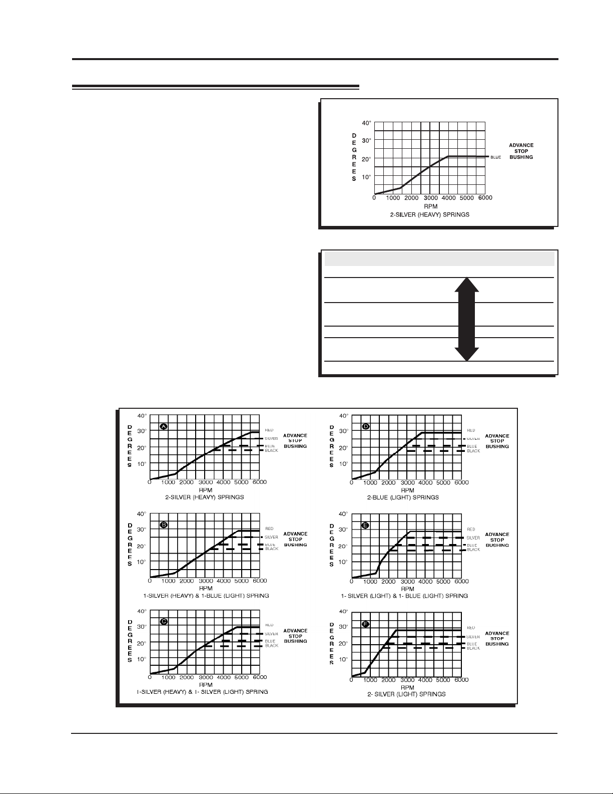
Timing Curve From Factory
Figure 2 The Factory Equipped Curve.
SPRING COMBINATION RATE OF ADVANCE FIGURE 4
2- Heavy Silver SLOWEST A
1- Heavy Silver B
1- Light Blue
1-Heavy Silver C
1-Light Silver
2- Light Blue D
1- Light Silver E
1- Light Blue
2- Light Silver FASTEST F
Figure 3 Spring Combination Chart.
Figure 4 Advance Curves.
M S D • W W W . M S D P E R F O R M A N CE . C O M • ( 9 1 5 ) 8 5 7 - 5 2 00 • F A X ( 9 1 5 ) 8 5 7 - 3 3 4 4
Page 4

4 INSTALLATION INSTRUCTIONS
SELECTING THE ADVANCE STOP
BUSHING
Three different advance stop bushings are supplied
in the distributor kit. The distributor comes with a
Blue (21°) bushing already installed. If a different
amount of centrifugal advance is desired, follow
the next procedure to change the bushings. The
chart in Figure 5 gives the size and approximate
degrees for the corresponding bushings.
CHANGING THE ADVANCE STOP
BUSHINGS
1. Remove the distributor cap and rotor.
2. Remove the locknut and washer on the bottom
of the advance assembly (Figure 6).
3. Remove the bushing and install the new one.
Ins tall t he was her and l ockn ut. Do not
overtighten.
BUSHING SIZE APPROXIMATE
CRANKSHAFT
DEGREES
Red-Smallest 28
Silver 25
Blue 21
Black-Largest 18
Figure 5 Advance Stop Bushing Chart.
LOCKING OUT THE CENTRIFUGAL
ADVANCE
1. Remove the advance components including the
springs, weights and the advance stop bushing
from the advance assembly.
2. Remove the roll-pin from the drive gear and
remove the gear from the shaft.
3. Slide the shaft two inches out of the housing.
4. Rotate the shaft 180° and insert the advance stop
bushing pin into the small hole on the advance
plate (Figure 7).
5. Install the locknut and washer to the advance
stop bushing pi n. This locks the advance in
place. Do not overtighten.
6. Install the drive gear and roll-pin.
Figure 6 Changing the Advance Stop Bushing.
Figure 6 Locking Out the Centrifugal Advance.
Figure 7 Locking Out the Advance.
M S D • W W W . M S D P E R F O R M A N CE . C O M • ( 9 1 5 ) 8 5 7 - 5 2 00 • F A X ( 9 1 5 ) 8 5 7 - 3 3 4 4
Page 5

INSTALLATION INSTRUCTIONS 5
INSTALLING THE DISTRIBUTOR
1. Remove the existing distributor cap without
disconnecting any of the spark pl ug
wires.
2. With the cap off, crank the engine until the
rotor is aimed at a fixed point on the engine
or firewall. Note this position by making a
mark (Figure 8).
3. Place the distributor cap back on and
note which plug wire the rotor is pointing
to. MARK THE SPARK PLUG WIRES and
remove the distributor cap.
4. D is c on n e ct th e w i ri n g f r o m t h e
distributor.
5. Loosen the distributor hold down clamp
and slide the clamp out of the way.
6. Lift the distributor out of the engine.
Note that the rotor rotates as you lift
the distributor out. T his is due to the
helical cut gear and should be taken into
consideration when installing the new
distributor.
7. Instal l the gasket and apply a liber al
amount of the supplied lubricant to the
distributor gear. (The supplied O-rings
can only be used if the block has been
modified as shown in Figure 9.)
8. Install the distributor making sure that the
rotor comes to rest pointing at the fixed
mark. If the distributor will not fully seat with
the rotor pointing to the marked position,
you may need to rotate the oil pump shaft
until the rotor lines up and the distributor
fully seats.
9. Position and tighten the hold down clamp
onto the distributor.
10. Install the distributor cap and spark plug wires one at a time to ensure correct location.
Figure 8 Marking the Rotor Location.
NOTE: BLOCK MUST BE MODIFIED TO USE O-RINGS.
Figure 9 Modified Block for use with O-Rings.
M S D • W W W . M S D P E R F O R M A N CE . C O M • ( 9 1 5 ) 8 5 7 - 5 2 0 0 • F A X ( 9 1 5 ) 8 5 7 - 3 3 4 4
Page 6

6 INSTALLATION INSTRUCTIONS
WARNING: High voltage is present on the coil terminals. Do not touch the terminals or
coil tower when the engine is cranking or running.
Figure 10 Wiring to an MSD 6-Series Ignition Control.
Figure 11 Wiring to an MSD 7-Series Ignition Control.
M S D • W W W . M S D P E R F O R M A N CE . C O M • ( 9 1 5 ) 8 5 7 - 5 2 0 0 • F A X ( 9 1 5 ) 8 5 7 - 3 3 4 4
Page 7
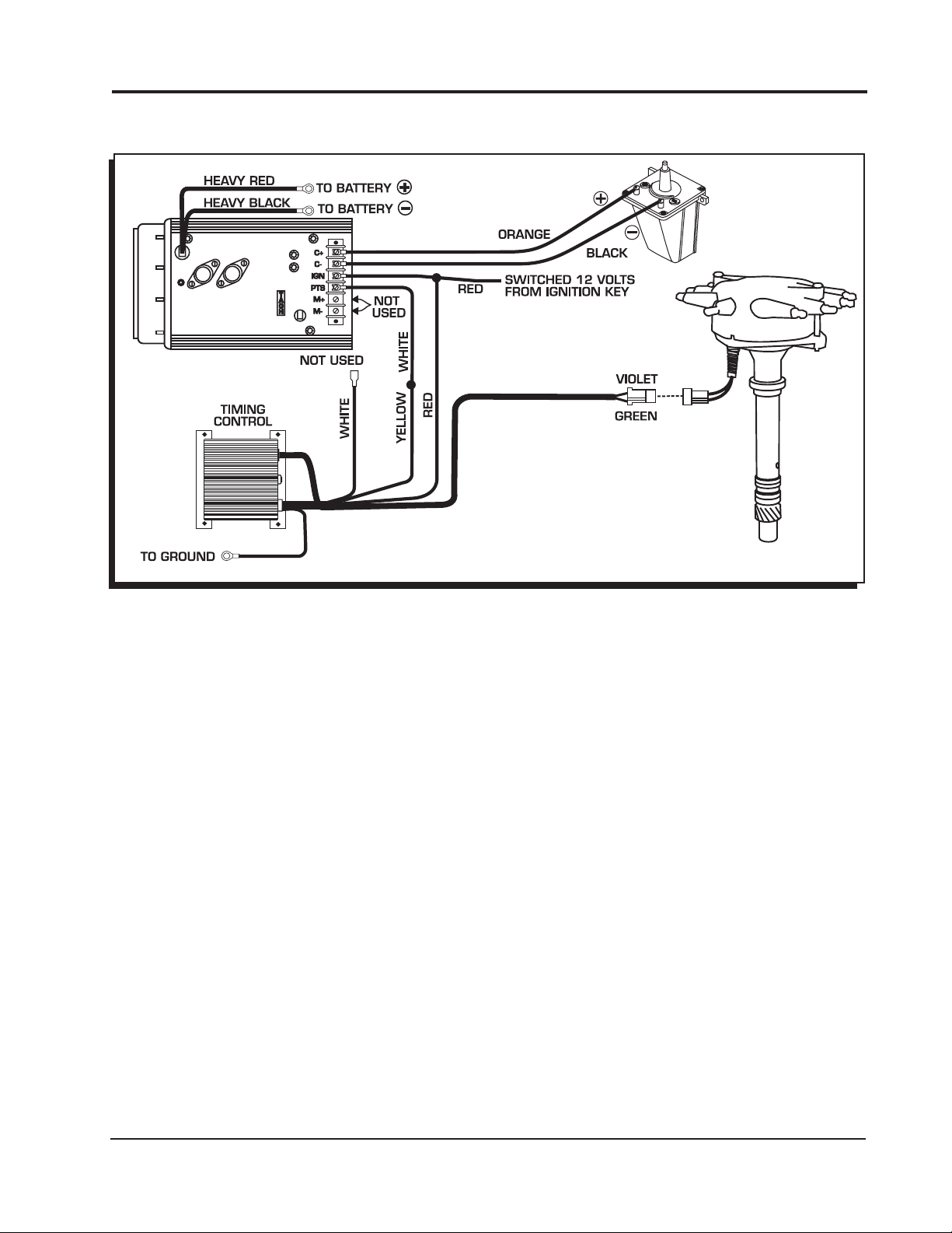
INSTALLATION INSTRUCTIONS 7
Note: MSD 6 and 7 Series Ignitions
share the same color wiring.
Figure 12 Wiring with an MSD 7-Series Ignition and Timing Control.
TECH NOTES
_________________________________________________________________________________________________________________________
_________________________________________________________________________________________________________________________
_________________________________________________________________________________________________________________________
_________________________________________________________________________________________________________________________
_________________________________________________________________________________________________________________________
_________________________________________________________________________________________________________________________
_________________________________________________________________________________________________________________________
_________________________________________________________________________________________________________________________
_________________________________________________________________________________________________________________________
_________________________________________________________________________________________________________________________
_________________________________________________________________________________________________________________________
_________________________________________________________________________________________________________________________
_________________________________________________________________________________________________________________________
_________________________________________________________________________________________________________________________
_________________________________________________________________________________________________________________________
_________________________________________________________________________________________________________________________
_________________________________________________________________________________________________________________________
M S D • W W W . M S D P E R F O R M A N CE . C O M • ( 9 1 5 ) 8 5 7 - 5 2 0 0 • F A X ( 9 1 5 ) 8 5 7 - 3 3 4 4
Page 8

TECH NOTES
_________________________________________________________________________________________________________________________
_________________________________________________________________________________________________________________________
_________________________________________________________________________________________________________________________
_________________________________________________________________________________________________________________________
_________________________________________________________________________________________________________________________
_________________________________________________________________________________________________________________________
_________________________________________________________________________________________________________________________
_________________________________________________________________________________________________________________________
_________________________________________________________________________________________________________________________
_________________________________________________________________________________________________________________________
_________________________________________________________________________________________________________________________
_________________________________________________________________________________________________________________________
_________________________________________________________________________________________________________________________
_________________________________________________________________________________________________________________________
_________________________________________________________________________________________________________________________
_________________________________________________________________________________________________________________________
_________________________________________________________________________________________________________________________
_________________________________________________________________________________________________________________________
Service
In case of malfunction, this MSD component will be repaired free of charge according to the terms of the warranty.
When returning MSD components for warranty service, Proof of Purchase must be supplied for verification. After
the warranty period has expired, repair service is based on a minimum and maximum fee.
All returns must have a Return Material Authorization (RMA) number issued to them before
being returned. To obtain an RMA number please contact MSD Customer Service at 1 (888) MSD-7859 or visit
our website at www.msdperformance.com/rma to automatically obtain a number and shipping information.
When returning the unit for repair, leave all wires at the length in which you have them installed. Be sure to include
a detailed account of any problems experienced, and what components and accessories are installed on the vehicle.
The repaired unit will be returned as soon as possible using Ground shipping methods (ground shipping is covered
by warranty). For more information, call MSD at (915) 855-7123. MSD technicians are available from 7:00 a.m. to
5:00 p.m. Monday - Friday (mountain time).
Limited Warranty
M
SD warrants this product to be free from defects in material and workmanship under its intended normal use*,
when properly installed and purchased from an authorized MSD dealer, for a period of one year from the date of
the original purchase. This warranty is void for any products purchased through auction websites. If found to be
defective as mentioned above, it will be repaired or replaced at the option of MSD. Any item that is covered under
this warranty will be returned free of charge using Ground shipping methods.
This shall constitute the sole remedy of the purchaser and the sole liability of MSD. To the extent permitted by
law, the foregoing is exclusive and in lieu of all other warranties or representation whether expressed or implied,
including any implied warranty of merchantability or fitness. In no event shall MSD or its suppliers be liable for special
or consequential damages.
*Intended normal use means that this item is being used as was originally intended and for the original application
as sold by MSD. Any modifications to this item or if it is used on an application other than what MSD markets the
product, the warranty will be void. It is the sole responsibility of the customer to determine that this item will work for
the application they are intending. MSD will accept no liability for custom applications.
M S D • W W W . M S D P E R F O R M A N CE . C O M • ( 9 1 5 ) 8 5 7 - 5 2 0 0 • F A X ( 9 1 5 ) 8 5 7 - 3 3 4 4
© 2012 Autotr onic Contr ols Corporation
FRM28512 Revised 02/12 Printed in U.S.A.
 Loading...