

Page 1
MSD Pro-Billet Honda Distributor
PN 8488
ONLINE PRODUCT REGISTRATION: Register your MSD product online and you’ll be entered
in our monthly 8.5mm Super Conductor Spark Plug Wire give-away! Registering your product
will help if there is ever a warranty issue with your product and helps the MSD R&D team create
new products that you ask for! Go to www.msdperformance.com/registration.
IMPORTANT: Read the instructions before attempting the installation.
Parts Included:
1 - Honda Distributor
1 - Parts Bag
1 - Wire Retainer
5 - 90° Boots and Terminals
WARNING: During installation, disconnect the battery cables. When disconnecting the battery,
always remove the Negative cable first and install it last.
WARNING: The Blaster SC Coil and Coil Driver produce very high voltage and current. Use
caution during installation and while working near the Coil assembly.
Note: The MSD Distributor Cap requires spark plug style 90° terminals and boots, which are supplied.
MSD also offers complete wire sets with the correct terminals and lengths. For more information, contact MSD or go to www.msdignition.com.
The MSD Pro-Billet Honda Distributor must be used with the SC Coil Driver, PN 6305, and Blaster SC
Coil, PN 8235. An MSD SCI, 6-Series and 7-Series Ignition Control may be used, but not required.
1 - Mini-Stripper-Crimper Tool
Components Required:
1 - SC Coil Driver, PN 6305
1 - Blaster SC Coil, PN 8235
REMOVAL
IMPORTANT: Ch ec k an d es ta bl is h
the ignition timing prior
to removing the original
distributor.
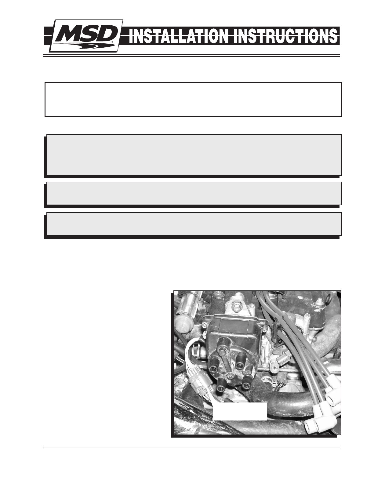
1. Clean the area around the distributor
and the engine to remove any loose
debris. Disconnect the distributor
connector.
2. Mark the location of each spark plug
wire, then remove the wires from the
distributor (Figure 1).
3. Remove the three 12mm bolts that
secure the distributor to the engine.
Remove the distributor by pulling it
straight out of the engine.
Figure 1 Removing the Wires and Factory Distributor.
M S D • W W W . M S D P E R F O R M A N C E . C O M • ( 9 1 5 ) 8 5 7 - 5 2 0 0 • F A X ( 9 1 5 ) 8 5 7 - 3 3 4 4
3
1
DISTRIBUTOR
CONNECTOR
4
2
4
2
3
Page 2
2 INSTALLATION INSTRUCTIONS
INSTALLATION
1. Apply a film of oil to the new O-ring and install it to the base of the distributor.
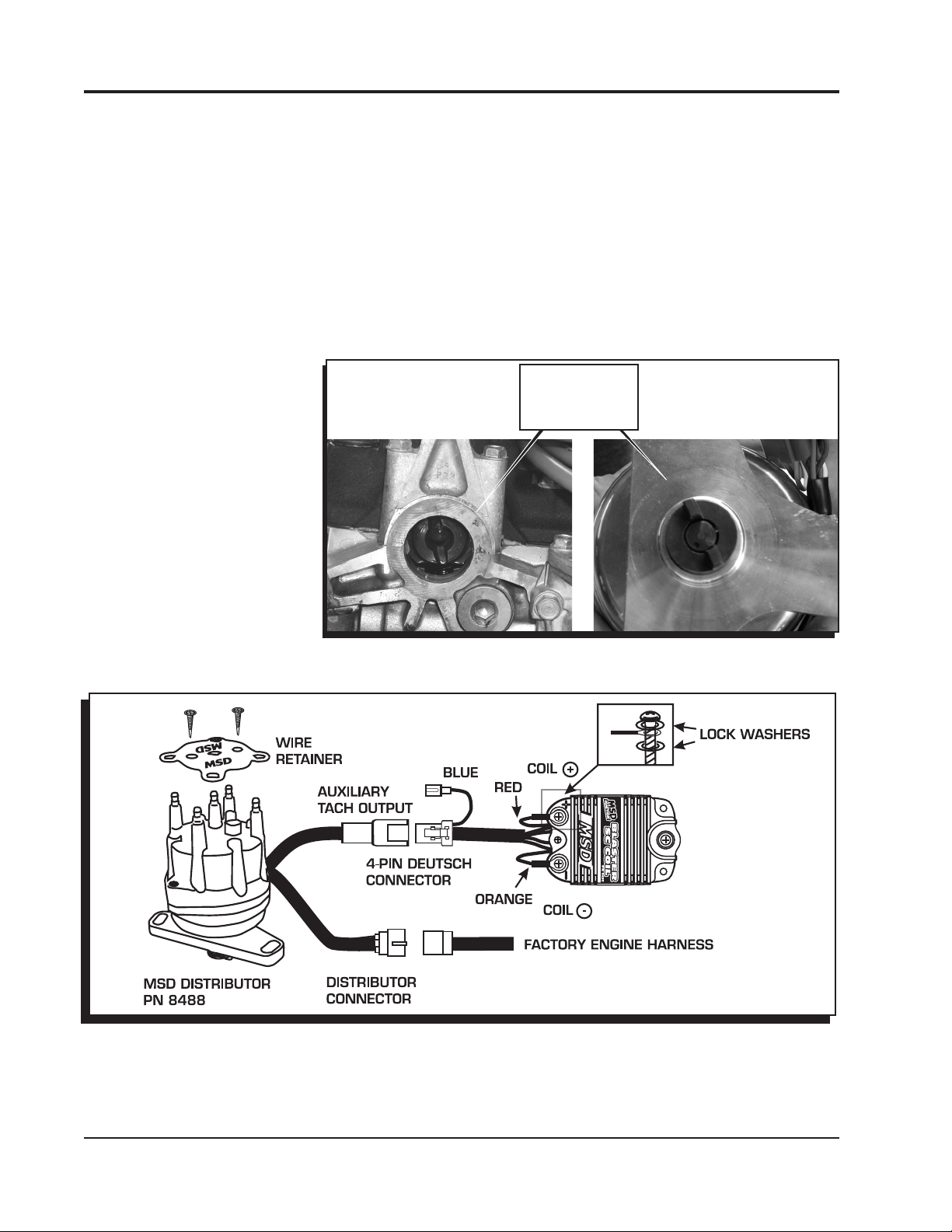
2. Note the distributor drive. It has two offset tabs that allow the distributor to be installed only in the
correct position (Figure 2). Line up these tabs with those of the camshaft and install the distributor
into the engine.
3. Install the three 12mm bolts to secure the distributor to the engine. Do not tighten them at this time
(The timing will require adjustment ).
4. Connect the distributor connector into the engine harness (Figure 3).
5. Connect the 4-pin Deutsch connector to the matching connector of the MSD Coil Driver (Figure
3). The factory tach will function without connecting the Blue auxiliary tach wire.
6. A set of terminals and boots have been supplied so most wires can be converted from the factory
socket terminals to the improved terminals of the MSD Distributor. Install the spark plug wires
making sure they are in
the correct firing order. For
Crimping Instructions, see
the following procedure on
page 3.
7. Install the MSD wire retainer
with the supplied screws
(Figure 3).
8. Start the engine and set the
ignition timing to the factory
specifications. Once set,
torque the three distributor
bolts to 16-18 lb-ft.
ENGINE DISTRIBUTOR
OFFSET
ALIGNMENT
TABS
Figure 2 Aligning the Distributor and Camshaft.
Figure 3 Wiring the Coil and Driver to the Distributor.
M S D • W W W . M S D P E R F O R M A N C E . C O M • ( 9 1 5 ) 8 5 7 - 5 2 0 0 • F A X ( 9 1 5 ) 8 5 7 - 3 3 4 4
Page 3

INSTALLATION INSTRUCTIONS 3
WIRING AN MSD IGNITION CONTROL
An MSD Ignition Control is not required but can be installed. Figure 4 shows the wiring when using
an MSD CD Ignition Control such as an SCI, 6-Series or even and MSD 7-Series Ignition Control.
Figure 4 Wiring the Coil and Driver with an MSD CD Ignition Control.
CRIMPING WITH THE MINI-STRIPPER-CRIMPER
1. Slide the wire into the cutting die as shown in Figure 5.
2. After stripping the sleeve, position the wire in the terminal so
the insulation protrudes about 1/8" beyond the insulation crimp
tabs and the conductor extends about 1/8" past the conductor
crimp tabs (Figure 6). Slide the other part of the Mini-StripperCrimper over the wire terminal and lightly press them together
(Figure 7).
3. Position the wire and terminal into the "W" groove of the MiniStripper Crimper and follow Steps 4 - 6 to crimp the terminal
to the sleeve.
Note: It is normal for the conductor to retract into the insulation
slightly as the sleeve crimp is made.
4. Put the assembly into a vise making sure the alignment tabs
are on the outside edge of the vise jaws (Figure 8).
5. Slowly close the vise making sure the tool and terminal stay
properly positioned and aligned (Figure 9). Stop applying
pressure when the terminal ends have wrapped securely
around the sleeve and grip the wire.
Note: DO NOT OVER CRIMP! It is possible to tear the sleeve
of the wire by excessive pressure on the vise. This will
cause a weaker crimp.
Figure 5 Stripping the Sleeve.
6. After the sleeve is crimped, push the conductor between the
crimp tabs and use a set of needlenose pliers to crimp them
together. DO NOT OVER CRIMP.
Figure 6 Crimping a Dual Crimp Terminal.
7. Slide the boot over the terminal and install the wire.
M S D • W W W . M S D P E R F O R M A N C E . C O M • ( 9 1 5 ) 8 5 7 - 5 2 0 0 • F A X ( 9 1 5 ) 8 5 7 - 3 3 4 4
Page 4

Figure 7
Aligning the Terminal in Tool.
Figure 8
Preparing to Crimp in the Vise.
Crimping with the Vise.
Figure 9
Service
In case of malfunction, this MSD component will be repaired free of charge according to the terms of the warranty.
When returning MSD components for warranty service, Proof of Purchase must be supplied for verification. After
the warranty period has expired, repair service is based on a minimum and maximum fee.
All returns must have a Return Material Authorization (RMA) number issued to them before
being returned. To obtain an RMA number please contact MSD Customer Service at 1 (888) MSD-7859 or visit
our website at www.msdperformance.com/rma to automatically obtain a number and shipping information.
When returning the unit for repair, leave all wires at the length in which you have them installed. Be sure to include
a detailed account of any problems experienced, and what components and accessories are installed on the vehicle.
The repaired unit will be returned as soon as possible using Ground shipping methods (ground shipping is covered
by warranty). For more information, call MSD at (915) 855-7123. MSD technicians are available from 7:00 a.m. to
5:00 p.m. Monday - Friday (mountain time).
Limited Warranty
M
SD warrants this product to be free from defects in material and workmanship under its intended normal use*,
when properly installed and purchased from an authorized MSD dealer, for a period of one year from the date of
the original purchase. This warranty is void for any products purchased through auction websites. If found to be
defective as mentioned above, it will be repaired or replaced at the option of MSD. Any item that is covered under
this warranty will be returned free of charge using Ground shipping methods.
This shall constitute the sole remedy of the purchaser and the sole liability of MSD. To the extent permitted by
law, the foregoing is exclusive and in lieu of all other warranties or representation whether expressed or implied,
including any implied warranty of merchantability or fitness. In no event shall MSD or its suppliers be liable for special
or consequential damages.
*Intended normal use means that this item is being used as was originally intended and for the original application
as sold by MSD. Any modifications to this item or if it is used on an application other than what MSD markets the
product, the warranty will be void. It is the sole responsibility of the customer to determine that this item will work for
the application they are intending. MSD will accept no liability for custom applications.
M S D • W W W . M S D P E R F O R M A N C E . C O M • ( 9 1 5 ) 8 5 7 - 5 2 0 0 • F A X ( 9 1 5 ) 8 5 7 - 3 3 4 4
© 2012 Autotr onic Co ntrols Corpor ation
FRM28725 Revised 02/12 Printed in U.S.A.
 Loading...