

Page 1
DIS CPC Signal Converter
PN 6304
Parts Included:
1 – DIS CPC Signal Converter
1 – Parts Bag
The MSD DIS CPC Signal Converter wires inline on the factory coil harness. It allows for the installation
of an MSD DIS-4 Series Ignition Control and Coils on vehicles with factory transistorized/driver style
coils. It achieves this by inverting the logic signal from the ECU and creating an output signal designed
to trigger the points input of an MSD DIS Ignition. The PN 6304 will not drive a coil.
Note: There are a number of different applications that can use the PN 6304. These instructions
illustrate a couple different installations. It is recommended to have the wiring schematic of
your vehicle prior to installation.
Coils: MSD recommends the PN 8207 Blaster SS Coil for Coil-per-Cylinder systems or PN 8204
(available from MSD Powersports).
MOUNTING
The DIS CPC Signal Converter is designed to be mounted under the hood. The circuits are potted
in polyurethane for water resistance and vibration protection. Position the unit away from excessive
heat sources and mark the location of the three mounting holes. Use a 5/32” bit to drill the holes and
secure the unit with the supplied screws.
WIRING
Route the wires away from any direct heat sources, rotating components, and sharp edges. The DIS
CPC Signal Converter comes with both male and female bullet terminals installed on the harness.
These terminals are designed to plug directly into the harness of an MSD DIS-4 color to color. The
ring lugs supplied in the parts bag install on the black wires and are to be connected to a good
chassis ground.
M S D I G N I T I O N • ww w. msd ig ni tio n. co m • ( 9 15 ) 8 57 -5 20 0 • FA X (9 15) 85 7 -3 34 4
Page 2
2 INSTALLATION INSTRUCTIONS
R
E
D
(N
C
)
V
IO
L
E
T
V
IO
L
E
T
Y
E
L
L
O
W
Y
E
L
L
O
W
12-PIN CONNECTOR
LED MONITOR
TACH OUTPUT
G
R
E
E
N
W
H
IT
E
G
R
E
E
N
W
H
IT
E
VIOLET
YELLOW
WHITE
GREEN
BROWN/WHITE
BROWN/GREEN
BROWN/YELLOW
BROWN/VIOLET
INPUT WIRES
GREEN
YELLOW
VIOLET
WHITE
OUTPUT WIRES
BROWN/WHITE
BROWN/GREEN
BROWN/YELLOW
BROWN/VIOLET
+
-
+
-
+
-
+
-
COIL 1 COIL 2 COIL 3 COIL 4
BROWN/GREEN
BROWN/
ORANGE
BROWN/
WHITE
BROWN/
ORANGE
BROWN/
YELLOW
BROWN/
VIOLET
BUTT
SPLICE
RED
RED
VIOLET
YELLOW
GREEN
WHITE
BLACK/WHITE +12V
BROWNBROWN
GROUND
WHITE/BLUE
BLUE/RED
YELLOW/GREEN
GROUND
GROUND
GROUND
CAP
CAP
CAP
PN 6304
COIL 4
HARNESS
COIL 3
HARNESS
COIL 2
HARNESS
COIL 1
HARNESS
GOOD CHASSIS
GROUND
JUMPER
JUMPER
SIGNAL
SIGNAL
SIGNAL
SIGNAL
MSD PN 8207
COILS
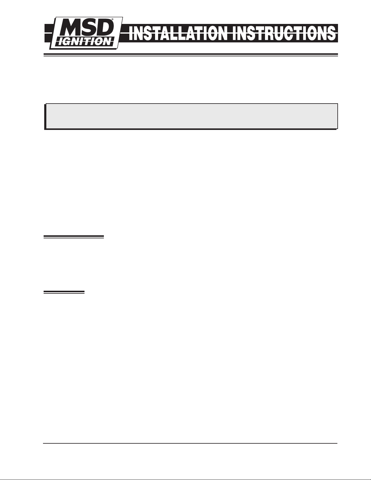
WIRE COLOR CODE OF DIS-4 IGNITION
Brown/White - Coil (-) Channel 1
Brown/Green - Coil (-) Channel 2
Brown/Yellow - Coil (-) Channel 3
Brown/Violet - Coil (-) Channel 4
Brown/Orange - Coil (+) High Voltage
White - Trigger Input Channel 1
Green - Trigger Input Channel 2
Yellow - Trigger Input Channel 3
Violet - Trigger Input Channel 4
Red (Heavy) - Battery (+)
Black (Heavy) - Battery (-)
Red - Ignition 12 Volt (Switched)
Pink - Step Retard (to 12 Volts)
Blue - Two Step (to 12 Volts)
Brown - No Spark output when Grounded
W
H
IT
E
W
H
IT
E
G
R
E
E
N
G
R
E
E
N
8-PIN CONNECTOR
LED MONITOR
TACH OUTPUT
BLACK
GOOD CHASSIS
GROUND
WHITE
GREEN
VIOLET
YELLOW
BROWN/GREEN
BROWN/WHITE
BROWN/YELLOW
BROWN/VIOLET
INPUT WIRES
WHITE
GREEN
OUTPUT WIRES
BROWN/WHITE
BROWN/GREEN
BROWN/
ORANGE
BROWN/
GREEN
BROWN/
ORANGE
BUTT
SPLICE
RED
GREEN
WHITE
(NC)
(NC)
(NC)
(NC)
BROWN/
WHITE
GROUND
GROUND
+12V
SIGNAL
SIGNAL
COIL 2
HARNESS
COIL 1
HARNESS
PN 6304
CAP
12V
1
2
R
E
D
(N
C
)
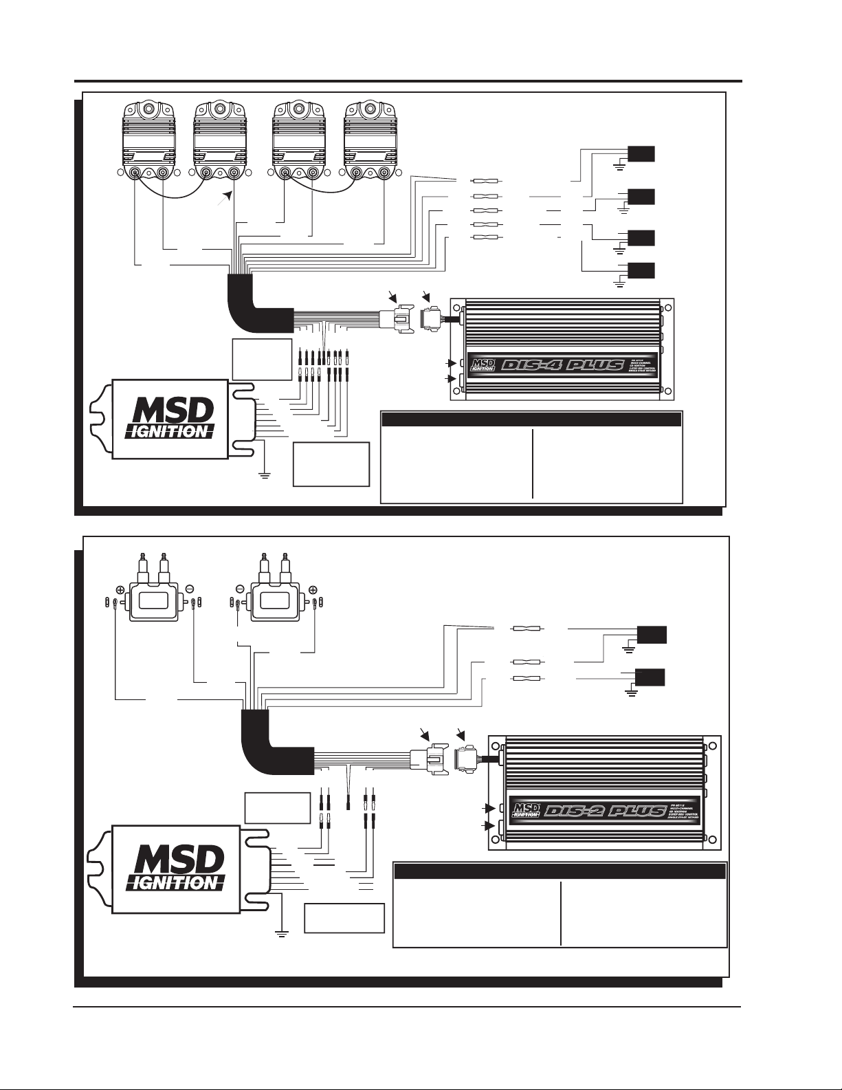
WIRE COLOR CODE OF DIS-4 IGNITION
Brown/White - Coil (-) Channel 1
Brown/Green - Coil (-) Channel 2
Brown/Orange - Coil (+) High Voltage
White - Trigger Input Channel 1
Green - Trigger Input Channel 2
Red - Ignition 12 Volt (Switched)
Pink - Step Retard (to 12 Volts)
Brown - No spark output
when grounded
Red (Heavy) - Battery (+)
Black (Heavy) - Battery (-)
Blue - Two Step (to 12 Volts)
Figure 1 Honda Wiring
M S D I G N I T I O N • ww w. msd ig ni tio n. co m • ( 9 15 ) 8 57 -5 20 0 • FA X (9 15) 85 7 -3 34 4
Figure 2 Typical 4-cylinder Wasted Spark Wiring.
Page 3

INSTALLATION INSTRUCTIONS 3
V
IO
L
E
T
V
IO
L
E
T
Y
E
L
L
O
W
Y
E
L
L
O
W
G
R
E
E
N
G
R
E
E
N
W
H
IT
E
W
H
IT
E
VIOLET
YELLOW
WHITE
GREEN
BROWN/WHITE
BROWN/GREEN
BROWN/YELLOW
BROWN/VIOLET
(NC)
(NC)
R
E
D
(N
C
)
GROUND
V
IO
L
E
T
V
IO
L
E
T
Y
E
L
L
O
W
Y
E
L
L
O
W
12-PIN CONNECTOR
LED MONITOR
TACH OUTPUT
G
R
E
E
N
G
R
E
E
N
W
H
IT
E
W
H
IT
E
BLACK
VIOLET
YELLOW
WHITE
GREEN
BROWN/WHITE
BROWN/GREEN
BROWN/YELLOW
BROWN/VIOLET
BUTT
SPLICE
FRONT
RED
VIOLET(NC)
WHITE
GREEN
YELLOW
BLACK/WHITE +12V
YELLOW/RED
BLUE/RED
PURPLE/WHITE
12-PIN CONNECTOR
LED MONITOR
TACH OUTPUT
BLACK
BROWN/GREEN
BROWN/ORANGE
BROWN/WHITE
BROWN/YELLOW
BROWN/ORANGE
BROWN/GREEN
BROWN/ORANGE
BROWN/WHITE
BROWN/ORANGE
BROWN/YELLOW
BUTT
SPLICE
RED
RED
VIOLET
YELLOW
GREEN
WHITE
BLACK/WHITE +12V
(NC)
GRAY/RED
GREEN/RED
OR GREEN/BLACK
GRAY
STOCK
COIL
HARNESS
STOCK
COIL
HARNESS
+
+
-
+
-
+
-
COIL 2 COIL 4 COIL 6 COIL 1
+
-
+
-
COIL 3 COIL 5
PN 6304
PN 6304
(NC)
(NC)
R
E
D
(N
C
)
BROWN/
ORANGE
BROWN/
ORANGE
GOOD CHASSIS
GROUND
GOOD CHASSIS
GROUND
GROUND
(N
C
)
(NC)
INPUT WIRES
WHITE
GREEN
YELLOW
VIOLET (NC)
OUTPUT WIRES
BROWN/WHITE
BROWN/GREEN
BROWN/YELLOW
BROWN/VIOLET (NC)
INPUT WIRES
WHITE
GREEN
YELLOW
VIOLET (NC)
OUTPUT WIRES
BROWN/WHITE
BROWN/GREEN
BROWN/YELLOW
BROWN/VIOLET (NC)
CYLINDER #2 - GREEN/RED OR GREEN/BLACK
CYLINDER #4 - GRAY
CYLINDER #6 - GRAY/RED
CYLINDER #1 - YELLOW/RED
CYLINDER #3 - BLUE/RED
CYLINDER #5 - PURPLE/WHITE
B
A
FIRING ORDER 1 2 3 4 5 6
IGNITION BOX A B A B A B
5
3
1
6
4
2
M S D I G N I T I O N • ww w. msd ig ni tio n. co m • ( 9 15 ) 8 57 -5 20 0 • FA X (9 15) 85 7 -3 34 4
Figure 3 Infinity G35 or Nissan 350-Z Wiring.
Page 4

TECH NOTES
_________________________________________________________________________________________________________________________
_________________________________________________________________________________________________________________________
_________________________________________________________________________________________________________________________
_________________________________________________________________________________________________________________________
_________________________________________________________________________________________________________________________
_________________________________________________________________________________________________________________________
_________________________________________________________________________________________________________________________
_________________________________________________________________________________________________________________________
_________________________________________________________________________________________________________________________
_________________________________________________________________________________________________________________________
_________________________________________________________________________________________________________________________
_________________________________________________________________________________________________________________________
_________________________________________________________________________________________________________________________
_________________________________________________________________________________________________________________________
_________________________________________________________________________________________________________________________
Service
In case of malfunction, this MSD component will be repaired free of charge according to the terms of the warranty.
When returning MSD components for warranty service, Proof of Purchase must be supplied for verification. After
the warranty period has expired, repair service is based on a minimum and maximum fee.
All returns must have a Return Material Authorization (RMA) number issued to them before
being returned. To obtain an RMA number please contact MSD Customer Service at 1 (888) MSD-7859 or
visit our website at www.msdignition.com/rma to automatically obtain a number and shipping information.
When returning the unit for repair, leave all wires at the length in which you have them installed. Be sure to include
a detailed account of any problems experienced, and what components and accessories are installed on the vehicle.
The repaired unit will be returned as soon as possible using Ground shipping methods (ground shipping is covered
by warranty). For more information, call MSD Ignition at (915) 855-7123. MSD technicians are available from 7:00
a.m. to 6:00 p.m. Monday - Friday (mountain time).
Limited Warranty
M
SD IGNITION warrants this product to be free from defects in material and workmanship under its intended normal
use*, when properly installed and purchased from an authorized MSD dealer, for a period of one year from the date
of the original purchase. This warranty is void for any products purchased through auction websites. If found to be
defective as mentioned above, it will be repaired or replaced at the option of MSD Ignition. Any item that is covered
under this warranty will be returned free of charge using Ground shipping methods.
This shall constitute the sole remedy of the purchaser and the sole liability of MSD Ignition. To the extent permitted
by law, the foregoing is exclusive and in lieu of all other warranties or representation whether expressed or implied,
including any implied warranty of merchantability or fitness. In no event shall MSD Ignition or its suppliers be liable
for special or consequential damages.
*Intended normal use means that this item is being used as was originally intended and for the original application
as sold by MSD Ignition. Any modifications to this item or if it is used on an application other than what MSD Ignition
markets the product, the warranty will be void. It is the sole responsibility of the customer to determine that this item
will work for the application they are intending. MSD Ignition will accept no liability for custom applications.
M S D I G N I T I O N • ww w. msd ig ni tio n. co m • ( 9 15 ) 8 57 -5 20 0 • FA X (9 15) 85 7 -3 34 4
© 2007 Autotronic Controls Corporation
FRM28074 Created 05/07 Printed in U.S.A.
 Loading...