

Page 1
Programmable Midget Racing Ignition Control
PN 6214
1 - Midget Ignition
1 - Magnet .250" x .200"
1 - Aluminum Magnet Rivet
1 - Pro-Data+ Disk
WARNING: During installation, disconnect the battery cables. When disconnecting the battery
always remove the Negative cable first and install it last.
Note: Solid Core spark plug wires cannot be used with the Midget Ignition.
The MSD Programmable Midget Ignition is a distributorless ignition system (DIS). It provides
powerful capacitive discharge sparks for complete combustion while providing a variety of
rpm and timing tuning programs. It consists of an Ignition Control, 2-Channel Coil Pack, and
incorporates a waste spark firing design. This means that two cylinders are fired at the same
time, one on the compression stroke and the other on the exhaust stroke. Two magnetic
pickups are used for trigger inputs and two outputs go to the supplied coil pack. The components offer a direct plug-in wiring harness with sealed, locking Deutsch Connectors. A 12
volt battery is required.
The MSD Programmable Midget Ignition Control requires a crank trigger system. MSD supplies two Non-Magnetic Pickups, but due to the variety of engines and applications, a crank
trigger wheel is not offered. Information is supplied on fabricating a crank trigger wheel.
Note: The Midget Ignition must be used on engines equipped with a battery.
1 - Wire Harness
2 - Ring Terminal (#6 Red)
2 - Ring Terminal (#1/4 Yellow)
1 - ON/OFF Toggle Switch
2 - PN 8159 Pickup
2 - 9-Pin Harness (6', 10')
4 - Vibration Mounts
GENERAL INFORMATION
DIGITAL OPERATION
The Programmable Midget Ignition uses a high speed RISC microcontroller to control the
ignition’s output while constantly analyzing the various inputs such as supply voltage, trigger
signals and rpm. The high speed controller can make extremely quick compensations to the
timing and rpm limits while maintaining accurate timing signals to within +/- 0.1° and +/- 10
rpm. The circuits and controller of the Ignition have been thoroughly debounced and suppressed to create protection against Electro Magnetic Interference (EMI).
Note: This Ignition can be removed from power and still retain its programmed settings.
CAPACITIVE DISCHARGE
The Midget Ignition features a capacitive discharge ignition design. The majority of stock
and aftermarket ignition systems are inductive ignitions. In an inductive ignition, the coil must
store energy and step up the supplied voltage to maximum strength between each firing. At
higher rpm, since there is less time to charge the coil to full capacity, the secondary voltage falls
short of reaching its maximum energy level which results in a loss of power or a top end miss.
The Midget Ignition features a capacitor which is quickly charged to 490 - 505 volts and
stores this energy until the ignition is triggered. With the CD design, the voltage sent to the
coil is always at maximum power even at high rpm.
MSD • WWW.MSDPERFORMANCE.COM • (915) 857-5200 • FAX (915) 857-3344
Page 2

2 INSTALLATION INSTRUCTIONS
MULTIPLE SPARKS
The Midget Ignition produces full power multiple sparks for each firing of a plug. The number
of multiple sparks that occur decreases as rpm increases, however the spark series always lasts
for 20° of crankshaft rotation. Above 1,200 rpm there is only one full power spark, for limiting
power drain on the battery. Multiple sparks will not activate unless rpm drops below 500 rpm.
BATTERY
The Midget Ignition Control will operate on any negative ground, 12 volt electrical system.
The Ignition can be used with 16 volt batteries and can withstand a momentary 24 volts in
case of jump starts. The Ignition will deliver full voltage with a supply of 11- 18 volts and will
operate momentarily with a supply voltage as low as 9 Volts.
If your application does not use an alternator, allow at least 17 amp/hour for every half hour
of operation. The Ignition uses about .8 Amps for every 1,000 rpm. If the engine is cranked
with the same battery or other accessories such as an electric fuel or water pump are used,
the amp/hour rating should be higher. Note: The negative battery terminal must be grounded
to the engine case.
COIL PACK
The MSD Programmable Midget Ignition should be used with the PN 8240 matched connector coil pack. For more information on recommended coils, contact our Customer Support
Department at (915) 855-7123.
TACHOMETERS
The Midget Ignition features a Tach Output Wire (Gray) and Black Ground wire. This wire
provides a trigger signal and ground for tachometers. The Tach Output Terminal produces a
12 volt square wave signal with a 30° duty cycle.
SPARK PLUGS AND WIRES
Spark plug wires are very important to the operation of your ignition system. A good quality, helically wound wire and proper routing are required to get the best performance from
your ignition, such as the MSD 8.5mm Super Conductor Wire. Helically wound wires provide
a good path for the spark to follow while keeping Electro Magnetic Interference (EMI) to a
minimum. Excessive EMI, such as the amount that solid core wires produce, may interfere
with the operation of the MSD. Solid Core spark plug wires cannot be used.
PROTECTION
The Programmable Midget Ignition has a built in reverse polarity protection circuit. This will
protect the ignition in the event of wrong connections. It will also shut off for protection from
a surge in power. The ignition will still operate once the surge or polarity is corrected.
LED INDICATOR
There is an LED that monitors the status of the Ignition. The LED will verify trigger inputs and
will flash trouble codes such as a Code 2 for Low Battery supply voltage.
PROGRAMMING OPTIONS
The Programmable Midget Ignition has many features that give you more control over
your timing and rev limits. For more information on programming these features, consult the
supplied Programming Instruction booklet, or see the Help menu in the Pro-Data+ Software.
MSD • WWW.MSDPERFORMANCE.COM • (915) 857-5200 • FAX (915) 857-3344
Page 3

INSTALLATION INSTRUCTIONS 3
HAND HELD PROGRAMMER, PN 7550
The Hand Held Programmer (Fig. 1) allows you to select and program the
different features of the Programmable Midget Ignition. The Ignition does
not need to be connected to the programmer in order to operate because
the program values are stored in an erasable memory circuit in the Ignition
Control. The Programmer only needs to be connected when you want to
check or change programs or to monitor different operating parameters.
Figure 1
PRO-DATA+ (INCLUDED)
MSD has a software package for your PC that allows you to create timing and rpm programs
for this ignition. All of the adjustable parameters can be reviewed and set, then uploaded to
the ignition. This software program is included to allow the upload and download of programs
for the Ignition Control as well as monitoring and editing of all the ignition's parameters. It will
work with any PC running Windows 95, 98, NT, ME, 2000 or XP. More information is available
in the Programming instructions. Visit our website to download the current version at www.
msdignition.com.
CYLINDER SELECTION
The Ignition default is for 4-cylinder operation only, using two mag pickups and two Ignition
Coils for waste spark operation.
PROGRAMMING FEATURES
The most current release of the MSD Pro-Data+ software is available which allows transferring all of the menu items and user data to the PC or from the PC to the timing controller
as well as viewing the Alternate and Run Timing curves and the monitored items. Also this
program allows editing the Alternate and Run timing curves on the PC.
the data to be printed out, timing plots and the other data items, from the Graph-View program.
RUN TIMING RETARD CURVE
This is the default timing curve and is active at all times unless the Alternate Timing Curve
is activated. This Curve is adjustable from 800 – 15,000 rpm and is programmable in 0.1°
increments every 100 rpm. The maximum amount of retard is 25°.
ALTERNATE TIMING RETARD CURVE
This feature provides the opportunity to switch to a second timing curve. This Curve will
override the Run Timing curve when the Dark Blue wire is supplied with 12 volts. It will remain
active until the 12 volts are removed (where the Run Curve becomes active again). This Curve
is adjustable from 800 – 15,000 rpm and is programmable in 0.1° increments every 100 rpm.
The maximum amount of retard is 25°.
Note: Both the Run Timing Curve and the Alternate Timing Curve defaults are zero degrees
of retard over the full RPM range.
START RETARD
This program will retard the timing when cranking to ease the load on the starter and flywheel. The retard will activate during cranking and will automatically turn off at 800 rpm. If
the engine drops below 500 rpm, the Start Retard rate will reactivate. The Start Retard has a
default setting of 15°.
This software allows all
MSD • WWW.MSDPERFORMANCE.COM • (915) 857-5200 • FAX (915) 857-3344
Page 4

4 INSTALLATION INSTRUCTIONS
REV LIMITER
An overrev rpm limit can be programmed in 100 rpm increments from 2,000 to 15,000 rpm.
The limiter has a default setting of 9,500 rpm.
IGNITION COMPENSATION
This compensation circuit is designed for MSD’s Crank Trigger Pickups and is automatic.
The circuit compensates for the inherent retard of magnetic pickups creating stable ignition
timing from idle to the maximum engine rpm. This function is automatic and does not require
any adjustments with the MSD pickups. Note: There is an offset of 4° from the input signals
to output signals to produce accurate timing. This must be taken into consideration when
statically setting the timing.
BATTERY MONITOR
This Ignition has a program that monitors the supply voltage of the battery in real time.
There are three different battery types that can be selected to automatically set a low voltage threshold by entering the number of cells that the battery has from six to 12. The battery
choices are Lead Acid, NIMH and NICAD. The default battery specification is a Lead Acid, 12
volt, six cell battery which has a low voltage threshold of 10.8 volts.
An example of some battery specs are:
12 volt Lead-Acid, 6 cell———10.8 volts
16 volt Lead-Acid, 8 cell———14.4 volts
12 volt NICAD,NIMH, 10 cell— 11.64 volts
The battery supply voltage is shown as BatVolts on the monitor.
Battery type is listed as BattType and BattCells displays the number of cells for selecting the
low thresehold.
13.2 volt NICAD,NIMH, 11 cell- 12.8 volts
14.4 volt NICAD,NIMH, 12 cell- 13.97 volts
BATTERY LOW PERCENTAGE MONITOR
This program is useful to see how the battery is holding up throughout a race. If the supply
voltage from the battery drops below the low voltage threshold, this monitor will display the
percentage of time that the voltage is below the recommended spec. This percentage is taken
from the entire time frame that the engine is run until it is shut off. This value will be stored in
the Ignition until the engine is started again. It is shown as %LOW on the monitor.
For example, if a race lasts 20 minutes (from the time the engine is started) and the voltage
dips below the threshold for 2 of those minutes, the %LOW value would be 10%. Note: If the
engine is started again, the program over writes the previous setting.
ALERTS
Alerts are messages that can be allowed to momentarily interrupt the current display screen
on the PN 7550 Monitor. The Alerts menu allows the user to select alert messages to be displayed, even to interrupt other screens, be scrolled through or skipped altogether. The default
of the Alerts/Scan program is set at 0 and will not show any alerts unless configured to show
any alerts. Until the user desires to change this feature to allow the alert mode of operation.
The alert messages at this time are: Low Spark and DisLost. More alert codes can be implemented as this component matures and as warranted by racer feedback.
OUTPUTS
An LED indicator is mounted on the 6214 end panel and can be used to verify trigger input
from mag-pickups. This LED also displays alert codes such as Low Spark code 2 by blinking
when this condition occurs. This alert code will be indicated both on the LED and the 7550
Monitor/Programmer/PC. An error condition of a lost pickup signal will indicate DisLost and
blink a code 3.
MSD • WWW.MSDPERFORMANCE.COM • (915) 857-5200 • FAX (915) 857-3344
Page 5
INSTALLATION INSTRUCTIONS 5
TRIGGER WHEEL FABRICATION
Due to the variety of engines and applications, a crank trigger wheel is not offered and must
be fabricated. The brackets for the two pickups must also be made.
The trigger wheel must be 3/8" thick for the MSD magnet to properly fit. The wheel can by
any type of non-magnetic material (aluminum, non-magnetic stainless, etc...) and can be any
diameter over 4”. MSD offers several trigger wheels for V8 applications that may be modified
for certain applications.
A magnet is supplied that must
be installed in the
trigger wheel. This
magnet must be
oriented in one position to produce
the correct trigger
signal for the non
magnetic pickups.
This is detailed in
Figure 2.
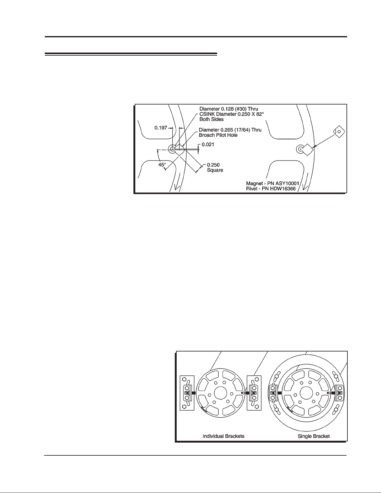
Figure 2 Mounting the Magnet in the Trigger Wheel.
1. Place the magnet in the wheel with the hole in the plastic overmolding facing the front of
the motor. The chamfer in the magnet must be positioned next to the hole for the aluminum
rivet.
2. Insert the aluminum rivet. The rivet must be set using a press or a vice with a set of smooth,
parallel jaws (such as the vice on a milling machine).
MOUNTING THE TRIGGER PICKUPS
Since the MSD Programmable Midget Ignition is a two channel, waste spark ignition system
there must be two trigger pickups. Brackets must be fabricated so the pickups are positioned
180° apart. Figure 3 shows two different mounting brackets.
Individual Brackets: Each pickup can be mounted on it’s own individual bracket 180° from
each other. In this configuration both pickups will need to be moved to make timing adjustments.
One Bracket: By using one bracket to position both pickups, timing adjustments will be easier
to set. The bracket will have to be slotted to make timing adjustments and one pickup will be
fixed and the other one will require adjustment slots to index it 180° from the other. Once the two
pickups are indexed correctly the
entire bracket will be able to be
rotated to make timing changes.
This configuration may be harder
to produce but has the advantage
of easier timing adjustments once
the pickups are indexed.
Care will have to be taken to ensure that the pickups remain 180 degrees apart.
Figure 3 Trigger Pickup Mounting Examples.
MSD • WWW.MSDPERFORMANCE.COM • (915) 857-5200 • FAX (915) 857-3344
Page 6

6 INSTALLATION INSTRUCTIONS
WIRING AND INSTALLATION
MOUNTING
The Ignition Control can be mounted in any position but should
be kept away from direct engine heat sources. It is fully potted with
a polyurethane compound and sealed. Make sure all of the wiring
reaches their connecting components. Four rubber mounts and
sleeves are supplied for installation and should be installed to the
Control as shown in Figure 4.
With everything mounted, connect all of the wiring harnesses
and secure them away from engine heat sources. The magnetic
pickup harnesses each have a ground wire which should be connected to engine ground.
WIRE FUNCTIONS
All of the wires, except the Power Leads, are supplied with Deutsch connectors already
terminated for a direct plug-in installation. It is not recommended to modify or lengthen any
wiring. Always route the wires away from direct heat sources and sharp edges. It is best to
route the trigger wires along a ground plane and away from the other wires.
Figure 4 Installing the
Vibration Mounts.
Large 2-Pin Connector: Power Leads
Large Red To the battery positive (+) terminal.
Large Black To battery negative (-) terminal or a common engine ground
Small 2-Pin Connector:
Red/Green wire
Red wire Connect to other side of the On/Off Switch
Violet/Green Magnetic Pickup, channel 1 (Violet is +, Green is -)
LT Blue/LTGreen Magnetic Pickup, channel 2 (LT Blue is +, LT Green is -)
Dark Blue This wire activates the Alternate Timing curve. When 12 volts are
applied, the Alternate Timing Curve is activated. When this wire is
removed from 12 volts the Alternate Curve is deactivated and timing
returns to the Run setting.
Gray Tach output, 12 volt, 20°- 30°duration. Note: Not compatible with
Magneto style Tachometers
Black Tachometer ground wire
Brown/White Connects to the negative terminal of Coil 1
Brown/Green Connects to the negative terminal of Coil 2
Brown/Orange Connects to the positive terminal of Coil 1
Brown/Orange Connects to the positive terminal of Coil 2
Connect to one side of the On/Off switch(+v source, internal fuse link)
8-Pin Connector:
Coil Connector, 4-Pin:
9-Pin connector Interface connector (RS232) to a PC or PN 7550 Programmer
MSD • WWW.MSDPERFORMANCE.COM • (915) 857-5200 • FAX (915) 857-3344
Page 7

INSTALLATION INSTRUCTIONS 7
Figure 5 Wiring the MSD Programmable Midget Ignition System.
Grounds: A poor ground connection can cause many frustrating problems. When a wire is
specified to go to ground, it should be connected to the battery negative terminal, engine
block and chassis. There should always be a ground strap between the engine and chassis.
Always securely connect the ground wire to a clean, paint free metal surface.
Spark plug wire routing: The MSD Coil Pack has two channels. With the coil's wiring harness facing you and looking from the top, the two terminals on the left are Channel 1 and the
two on the right are Channel 2. Channel 1 connects to the first and third cylinders in the firing
order. Channel two fires the second and fourth cylinders of the engine’s firing order. (Since
this is a waste spark system each channel of the coil fires its two cylinders at the same time.)
SETTING STATIC TIMING
By positioning the engine at your desired timing and lining up the trigger magnet and the
pickup, the timing will be close enough to start. Then your final adjustments can be set. Note
that a fully degreed hub is necessary for accurate timing settings.
Roll the engine over so cylinder #1 in the firing order is at the desired timing value then add
another 4°. This additional 4° is a computational lag associated with the magnetic pickups and
requires this compensation to achieve accurate timing throughout the entire rpm range. This
pickup should be connected to the Violet and Green wiring harness.
Next roll the engine over so the second cylinder in the firing order is at the desired timing
value (as used for the first cylinder). Line up the second pickup (Light Blue and Light Green
wires) with the magnet.
MSD • WWW.MSDPERFORMANCE.COM • (915) 857-5200 • FAX (915) 857-3344
Page 8

8 INSTALLATION INSTRUCTIONS
Note: When setting the static timing the timing must be set 4°advanced from maximum run
timing, this allows the IgnComp to automatically function to remove all timing retard caused
by pickups, ignition delays and coil rise-time delays.
Setting running ignition timing: Attach the inductive lead from the timing light to the number
one ignition wire. Set the desired timing by moving the primary pickup on it’s slotted bracket.
Now attach the inductive lead to the second cylinder (in the firing order) ignition wire and position the secondary pickup to your desired timing. Both pickups are now phased 180° apart.
Pro-Data+ Programming Instructions
These instructions will walk you through the different programming features of the Midget
Ignition using the Pro-Data+ Software. If you need help with the installation of the Midget
please refer to the Installation Instruction that came with your unit or you can download a new
set from our web site at www.msdignition.com
INSTALLATION
1. Insert the installation disk into your disk drive.
2. In Windows click “Start” then Select “Run”.
3. In the box type ”A:\Setup” Press Enter
4. Follow the on screen instructions.
5. At this point you should have two new icons on your desk top.
6. Select the one that says “MSD Graph View”
7. At this point you should see several timing graphs.
8. In the upper left corner of your screen select “File”
9. Scroll down and select “Open”
10. Select the folder that says “6214”
11. Highlight the file that says “6214vxx.IGN” (xx = The latest version #; Example "01")
12. Click Open
At this point you are in the default setting for the Programmable Midget Ignition. When you
make a change to this file always select the “Save As” option and rename the new file.
SAVES AND TRANSFERS
Whenever a change is made to a program, it either must be saved to your PC as part of the
file you are programming or it must be saved/transferred to the MSD. The software gives you
the choice of automatically transferring the change to the MSD or the PC.
Save to MSD: By saving the change right to the MSD, the new change is automatically put
into the Controller.
Save to PC: This saves the changes on your PC screen only. The information still must be
transferred to the MSD before it becomes active or saved to a file.
You can create numerous files with different options on our PC and download them at the
track for testing.
MSD • WWW.MSDPERFORMANCE.COM • (915) 857-5200 • FAX (915) 857-3344
Page 9

INSTALLATION INSTRUCTIONS 9
MONITOR
The rpm meter is a graphical interface that
allows you to monitor the rpm and retard functions of the Midget Ignition while the engine is
running. The dial on the left side will indicate
the rpm in real time. The dial on the right side
will show the total degrees retard.
Figure 6 RPM and Retard Monitor.
DEFAULT SETTINGS
The default settings are for a four cylinder engine with a Waste Spark (two spark plugs fire
at the same time). This ignition should only be used on 4-cylinder engine with two mag pickup
inputs, with two coils.
The following list shows all of the default values and adjustable increment of the Midget Ignition.
Display Default Data Low-High (step by)
RevMax ###00 Rpm 9,500 2,000-15,000 (100)
StartRetard ## Deg 15 0-25 (1)
BattType $$$$$ Lead Lead, NiCad, NiMH
BattCells ## 6 6-12 (1)
RunMap Rpm ###00 800 800-15,000 (100)
RunMap Deg ##.# 0 0-25.0 (0.1)
AltMap RPM ###00 800 800-15,000 (100)
AltMap Deg ##.# 0 0-25.0 (0.1)
AlertsPerScan # 0 0-1 (1)
REV LIMITER OPTIONS
RevMax – (Default 9,500)
This is the Max Rev Limiter. The options are from 2,000 rpm to
15,000 rpm in 100 rpm increments.
RevLim
RevMax
START RETARD OPTION
Start retard is used to ease the load on the starter and to prevent
backfires. This option is in effect from 0 to 800 rpm on start up. If
the engine drops below 500 rpm, it will activate again. It is adjustable in 1° increments from 0° - 25°. The default is 15°.
Retards
Starts
StartRetard
*Deg 10
MSD • WWW.MSDPERFORMANCE.COM • (915) 857-5200 • FAX (915) 857-3344
Page 10

10 INSTALLATION INSTRUCTIONS
ALTERNATE TIMING CURVE
AltCurve – (Default - See Graph)
The Midget Ignition allows you to
program a timing curve that is only
active when the Alt Wire is switched to
+12V. When this curve is active the word
active appears on the bottom of this
graph. This curve is programmable by
the graphical map. The easiest way to
achieve this is to maximize the box that
contains the Alt Curve. In order to move
the curve you will need to place your
mouse over the portion of the graph that
you would like to move. Right click your
mouse and select “Add Dot”. This will
give you a red dot that you will be able
to position anywhere along the curve.
Continue to do this until your curve is
completely mapped out. After this curve
has been edited, save it in the Midget
Ignition with a transfer - Plot to MSD or
File-Save As to save it in a file on the PC.
^Rpm 800 Alt
Copy RetDeg 0.0
RUN TIMING CURVE
RunCurve – (Default - See Graph)
The Run Curve is active when the
Alt Wire is not switched to +12V. The
Midget Ignition gives you the ability to
map out a complete timing curve from
800 rpm all the way to 15,000 rpm. This
timing curve can increase or decrease at
any point along the graph. The easiest
way to achieve this is to maximize the
box that contains the Run Timing Curve.
In order to move the curve you will need
to place your mouse over the portion of
the graph that you would like to move.
Right click your mouse and select “Add
Dot”. This will give you a red dot that you
will be able to position anywhere along
the curve. Continue to do this until your
curve is completely mapped out. After
this curve has been edited, save it in the
Midget Ignition with a transfer - Plot to
MSD or File-Save As to save it in a file
on the PC.
^Rpm 800 Run
Copy RetDeg 0.0
Note: Any graph can be printed by se-
lecting Transfer-Print. Also all other
parameters can be printed from the Data Editor-Select-Print.
MSD • WWW.MSDPERFORMANCE.COM • (915) 857-5200 • FAX (915) 857-3344
Page 11

INSTALLATION INSTRUCTIONS 11
Data Editor Window
Note:
6214 M01
Monitor
Stats
Stat 1
RevLim
RevMax
• Rpm 9500
Retards
RunCurve
• Rpm 800
Run
Copy@
RetDeg .0
6214V01. Uses menu 6214 M01. Programmable Midget Ignition Factory default data and menu.
Continued...
Start
StartRetard
• Deg15
AltCurve
• Rpm 800
Alt
Copy@
RetDeg .0
Continued...
Batt
• BattType Lead
• BattCells 6
Alerts
Alert 1
• (1) SCAN
• (1) SCAN
AlertsPer
• Alerts/Scan 0
ALERTS
Alerts – (Default - (1) Scan -
The Alerts will provide a flash code to the LED on the outside of
Alert (1) SCAN
LowSPARK
the Ignition.
This indicates a Low Battery situation. This will blink the LED two times.
The Options are: Scan (to enable)
Skip (to disable)
This indicates that the Ignition is not receiving a trigger signal from
one of the pickups. This will blink the LED three times.
Alert (2) SCAN
DisLost
MENU TREE
The following menu tree shows the different screens and programs of the PN 6214 and Monitor.
PN 6214 Flow Chat with Hand Held Monitor
Monitor List:
1 ScanTime 1Sec
2 DisIn OK
3 Rpm 12500
4 Retard 00.0
5 Curve RUN
6 BatVolt 12.0
7 BatThes 10.8
8 BattLow 12%
^s ScanTime 1Sec
H Rpm 12500
as displayed on the 7550 Terminal
^RevMax
Rpm ###00
6214 M01 Terminal Screens
Menus
Monitor Stats
RevLim Retards*
^RunCurve Start
AltCurve
Alert List
2.LowSpark
3. DisLost
^Stat 1 SCAN
ScanTime #Sec
Batt Alerts*
AlertsPer
^BattType$$$$
BattCells##
BattType
Lead
NiCad
NiMH
BattCells
6, 7, 8, 9, 10, 11, 12
^Alerts/Scan#
^Rpm###00 Run
Copy RetDeg##.#
^Rpm###00 Alt
Copy RetDeg##.#
^Alert# SCAN
LowSpark
DisLost
^StartRetard
Deg##
MSD • WWW.MSDPERFORMANCE.COM • (915) 857-5200 • FAX (915) 857-3344
Page 12

12 INSTALLATION INSTRUCTIONS
TROUBLESHOOTING
Every MSD Ignition undergoes numerous quality control checks including a four hour burn-in
test. If you experience a problem with your Midget Ignition, our research has shown that the
majority of problems are due to improper installation or poor connections. The Troubleshooting section has several checks and tests you can perform to ensure proper installation and
operation of the Midget Ignition. If you have any questions concerning your Midget Ignition,
call our Customer Support Department at (915) 855-7123, 8 - 5 Mountain Time, or e-mail at:
msdtech@msdignition.com.
LED
The LED on the side of the Midget Ignition monitors several operating conditions of the
Midget Ignition. If the LED indicates that there is a problem with the ignition system, follow
the steps through the Troubleshooting section. The LED will appear to be on steady at above
idle speeds when everything is functioning properly.
• A Code 2 (ash-ash)will occur if the supply voltage drops below 12 volts, when operat-
ing below 1200 rpm.
• A Code 3 (ash-ash-ash) will occur if a trigger signal is lost.
• The LED will ash for every trigger signal from the crank trigger. You can take advantage of
this when checking for input trigger signals.
MISSES AND INTERMITTENT PROBLEMS
Experience at the races has shown that if your engine is experiencing a miss or hesitation
at higher rpm, it is usually not directly ignition. Most probable causes include faulty wiring,
a coil or plug wire failure, arcing from the boot plug to ground. Several items to inspect are:
• Ensure that there is a good ground path from the engine and chassis to the negative terminal of the battery. Also confirm that the Black wire with a ring lug that exits the case is
grounded to the engine block.
• Always inspect the plug wires at the plug for a tight connection and visually inspect for cuts,
abrasions or burns. Dielectric grease such as Spark Guard, PN 8804, is also recom- mended.
• Inspect the Primary Coil Wire connections.
CAUTION: There may be high voltage at the Coil Positive (+) terminal even with the key turned
On. During cranking or while the engine is running, very high voltage will be present and no test equipment should be connected.
• Make sure that the battery is fully charged and the connections are clean and tight. If
you are not running an alternator this is an imperative check. If the battery voltage falls
below 11 volts during a race, the Midget Ignition current draw will increase.
• Is the engine running lean? Inspect the spark plugs and complete fuel system.
• Inspect all wiring connections for corrosion or damage. Remember to always use prop-
er connections followed by soldering and seal the connections completely.
WARNING: Do not touch the coil terminals during cranking or while the engine is running.
If everything checks positive, use the procedure on page 13 to test the ignition for spark.
MSD • WWW.MSDPERFORMANCE.COM • (915) 857-5200 • FAX (915) 857-3344
Page 13

INSTALLATION INSTRUCTIONS 13
CHECKING FOR SPARK
1. Make sure the ignition switch is in the “Off” position.
2. Remove the coil wires from the spark plug and set
them approximately 1/2" from ground.
3. Disconnect the magnetic pickup connectors from the
ignition.
4. Turn the ignition to the On position. Do not crank the
engine.
5. With a small jumper wire, short the Violet wire
to the Green wire (Pickup Channel 1), then pull
them apart (Figure 7). This will cause a
spark to jump from the plug wires to ground. If spark
is present, the ignition is working properly. Do the same test using the Light Blue and
Light Green trigger wires (Channel 2). If there is no spark procede to step 6:
6. If there is no spark:
A. Inspect all of the wiring.
B. Substitute another coil and repeat the test. If there is now spark, the coil is at
fault.
C. If there is still no spark, check to make sure there are 12 volts on the small Red
wire from the Midget Ignition when the ignition switch is in the On position. If
12 volts are not present, find another switched 12 volt source and repeat the
test.
D. If, after following the test procedures and inspecting all of the wiring, there is
still no spark, the Midget Ignition is in need of repair. See the Warranty and
Service section for information.
Figure 7 False Triggering Channel
MIDGET IGNITION TESTER, PN 8994
MSD also offers a Multi-Channel Ignition Tester (Fig. 8). This tool allows you to check your
complete ignition system while it is on the
vehicle as well as the operation of rpm
limits.
Figure 8 MSD Programmable Midget Ignition Tester.
If you experience difficulties when installing your MSD, contact our Customer Support Department at: (915) 855-7123 (8 - 5 Mountain time) or e-mail us at: msdtech@msdignition.com
MSD • WWW.MSDPERFORMANCE.COM • (915) 857-5200 • FAX (915) 857-3344
Page 14

14 INSTALLATION INSTRUCTIONS
Figure 12 - DIS SYSTEMS Wiring PN 8870 Coil Spacers with GM Ignitions.
_______________________________________________________________________________________
_______________________________________________________________________________________
_______________________________________________________________________________________
_______________________________________________________________________________________
_______________________________________________________________________________________
_______________________________________________________________________________________
_______________________________________________________________________________________
_______________________________________________________________________________________
_______________________________________________________________________________________
_______________________________________________________________________________________
_______________________________________________________________________________________
_______________________________________________________________________________________
_______________________________________________________________________________________
_______________________________________________________________________________________
_______________________________________________________________________________________
_______________________________________________________________________________________
_______________________________________________________________________________________
_______________________________________________________________________________________
_______________________________________________________________________________________
_______________________________________________________________________________________
_______________________________________________________________________________________
_______________________________________________________________________________________
_______________________________________________________________________________________
_______________________________________________________________________________________
_______________________________________________________________________________________
_______________________________________________________________________________________
_______________________________________________________________________________________
_______________________________________________________________________________________
_______________________________________________________________________________________
_______________________________________________________________________________________
_______________________________________________________________________________________
_______________________________________________________________________________________
_______________________________________________________________________________________
_______________________________________________________________________________________
_______________________________________________________________________________________
_______________________________________________________________________________________
_______________________________________________________________________________________
_______________________________________________________________________________________
_______________________________________________________________________________________
_______________________________________________________________________________________
MSD • WWW.MSDPERFORMANCE.COM • (915) 857-5200 • FAX (915) 857-3344
Tech Notes
Page 15

INSTALLATION INSTRUCTIONS 15
Tech Notes
_______________________________________________________________________________________
_______________________________________________________________________________________
_______________________________________________________________________________________
_______________________________________________________________________________________
_______________________________________________________________________________________
_______________________________________________________________________________________
_______________________________________________________________________________________
_______________________________________________________________________________________
_______________________________________________________________________________________
_______________________________________________________________________________________
_______________________________________________________________________________________
_______________________________________________________________________________________
_______________________________________________________________________________________
_______________________________________________________________________________________
_______________________________________________________________________________________
_______________________________________________________________________________________
_______________________________________________________________________________________
_______________________________________________________________________________________
_______________________________________________________________________________________
_______________________________________________________________________________________
_______________________________________________________________________________________
_______________________________________________________________________________________
_______________________________________________________________________________________
_______________________________________________________________________________________
_______________________________________________________________________________________
_______________________________________________________________________________________
_______________________________________________________________________________________
_______________________________________________________________________________________
_______________________________________________________________________________________
_______________________________________________________________________________________
_______________________________________________________________________________________
_______________________________________________________________________________________
_______________________________________________________________________________________
_______________________________________________________________________________________
_______________________________________________________________________________________
_______________________________________________________________________________________
_______________________________________________________________________________________
_______________________________________________________________________________________
_______________________________________________________________________________________
_______________________________________________________________________________________
MSD • WWW.MSDPERFORMANCE.COM • (915) 857-5200 • FAX (915) 857-3344
Page 16

TECH NOTES
_________________________________________________________________________________________________________________________
_________________________________________________________________________________________________________________________
_________________________________________________________________________________________________________________________
_________________________________________________________________________________________________________________________
_________________________________________________________________________________________________________________________
_________________________________________________________________________________________________________________________
_________________________________________________________________________________________________________________________
_________________________________________________________________________________________________________________________
_________________________________________________________________________________________________________________________
_________________________________________________________________________________________________________________________
_________________________________________________________________________________________________________________________
_________________________________________________________________________________________________________________________
_________________________________________________________________________________________________________________________
_________________________________________________________________________________________________________________________
_________________________________________________________________________________________________________________________
_________________________________________________________________________________________________________________________
_________________________________________________________________________________________________________________________
_________________________________________________________________________________________________________________________
Service
In case of malfunction, this MSD component will be repaired free of charge according to the terms of the warranty.
When returning MSD components for warranty service, Proof of Purchase must be supplied for verification. After
the warranty period has expired, repair service is based on a minimum and maximum fee.
All returns must have a Return Material Authorization (RMA) number issued to them before
being returned. To obtain an RMA number please contact MSD Customer Service at 1 (888) MSD-7859 or visit
our website at www.msdperformance.com/rma to automatically obtain a number and shipping information.
When returning the unit for repair, leave all wires at the length in which you have them installed. Be sure to include
a detailed account of any problems experienced, and what components and accessories are installed on the vehicle.
The repaired unit will be returned as soon as possible using Ground shipping methods (ground shipping is covered
by warranty). For more information, call MSD at (915) 855-7123. MSD technicians are available from 7:00 a.m. to
5:00 p.m. Monday - Friday (mountain time).
Limited Warranty
M
SD warrants this product to be free from defects in material and workmanship under its intended normal use*,
when properly installed and purchased from an authorized MSD dealer, for a period of one year from the date of
the original purchase. This warranty is void for any products purchased through auction websites. If found to be
defective as mentioned above, it will be repaired or replaced at the option of MSD. Any item that is covered under
this warranty will be returned free of charge using Ground shipping methods.
This shall constitute the sole remedy of the purchaser and the sole liability of MSD. To the extent permitted by
law, the foregoing is exclusive and in lieu of all other warranties or representation whether expressed or implied,
including any implied warranty of merchantability or fitness. In no event shall MSD or its suppliers be liable for special
or consequential damages.
*Intended normal use means that this item is being used as was originally intended and for the original application
as sold by MSD. Any modifications to this item or if it is used on an application other than what MSD markets the
product, the warranty will be void. It is the sole responsibility of the customer to determine that this item will work for
the application they are intending. MSD will accept no liability for custom applications.
MSD • WWW.MSDPERFORMANCE.COM • (915) 857-5200 • FAX (915) 857-3344
© 2013 Autotr onic Co ntrol s Corpo ratio n
FRM24055 Revised 03/13 Printed in U.S.A.
 Loading...