

Page 1
MSD LS Ignition Control
PN 6014/60143
ONLINE PRODUCT REGISTRATION: Register your MSD product online. Registering your product
will help if there is ever a warranty issue with your product and helps the MSD R&D team create
new products that you ask for! Go to www.msdperformance.com/registration.
Parts Included:
1 – LS Ignition Controller, PN 6014
1 – Main Wiring Harness
1 – Crank/Cam Pigtail 24x
1 – Crank/Cam Pigtail 58x
Optional Accessories (Purchased Separately):
LS Coolant Temp Sensor, GM PN 12608814
PN 2279 - 24x Crank/4x Cam
WARNING: During installation, disconnect the battery cables. When disconnecting, always re-
move the negative cable rst and install it last.
Note: Solid core spark plug wires cannot be used with an MSD Ignition Control.
1 – Sub Harness
1 – USB Cable
1 – Mounting Kit
1 – MSDView USB
OPERATION
The MSD 6014 LS Ignition controller works with 24x/1x, 58x/4x and 58x/1x crank/cam congurations. It auto detects the correct conguration based on the reluctor wheel pattern, so there is no
need to select one. It provides six pre-programmed (non-editable) timing tables for stock engines,
three customizable 3-D tables and one customizable timing plot. The desired table/plot is selected
on the y using the rotary dial. The customizable tables and plot can be programmed via MSDView.
The LS Ignition controller includes a built-in 2.5 Bar MAP sensor that can be used with Naturally
Aspirated or boosted applications. This allows for timing advance or retard based on the intake
manifold pressure.
8Mb of internal data logging is also included so you can setup, record and review runs at the track.
Note: It is recommended, that you install and run MSDView software while connected to the unit to
perform the base settings. The unit can be powered off of USB, so this can be done from a
desktop or laptop and does not require an external power source.
MSD • WWW.MSDPERFORMANCE.COM • (915) 855-7123 • FAX (915) 857-3344
Page 2
2 INSTALLATION INSTRUCTIONS
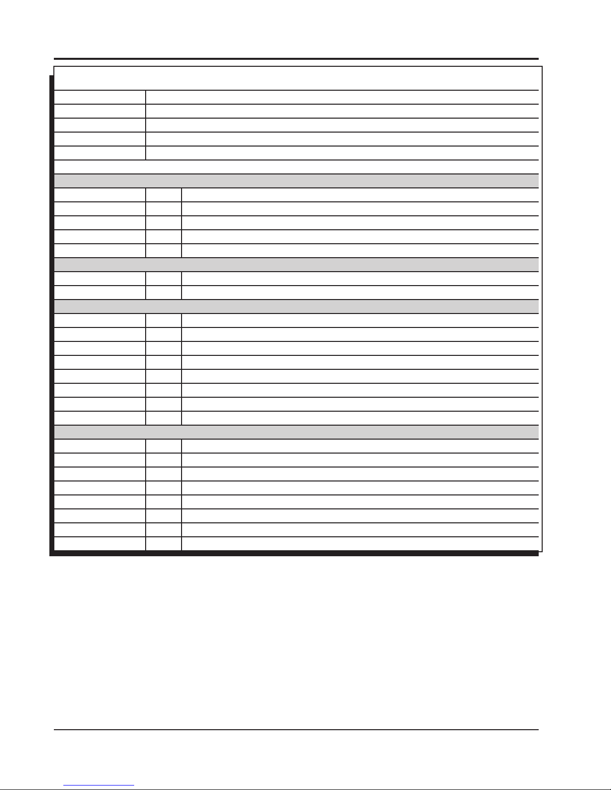
WIRING FEATURES
PINK Step Retard. When 12-volts are supplied, the Step Retard is activated.
BLUE Two-Step. When 12-volts are supplied, the Launch Rev Limiter RPM value is active.
GRAY Tach. Provides a 12-volt square wave signal.
RED Battery Positive. From relay or dedicated fused 30A switch.
BLACK Battery Negative
CAM/CRANK SENSOR - 10 PIN
ORANGE/YELLOW Pin-1 Crank
BROWN/WHITE Pin-2 Cam
ORANGE Pin-3 5-volt supply
PINK Pin-4 12-volt supply
BROWN Pin-6 Sensor Ground
ENGINE COOLANT TEMP SENSOR (ECT)
BLACK Pin-1 Sensor Ground
YELLOW Pin-2 Engine Coolant Signal
COIL CONNECTOR - EVEN CYLINDERS
BLACK Pin-A Chassis Ground
RED/GREEN Pin-B Coil 2
BROWN/GREEN Pin-C Coil 4
Pin-D Not Used
BROWN Pin-E Sensor Ground
WHITE/BLUE Pin-F Coil 6
VIOLET/BLUE Pin-G Coil 8
PINK Pin-H 12-volt supply
COIL CONNECTOR - ODD CYLINDERS
BLACK Pin-A Chassis Ground
RED Pin-B Coil 7
GREEN Pin-C Coil 5
Pin-D Not Used
BROWN Pin-E Sensor Ground
BLUE Pin-F Coil 3
VIOLET Pin-G Coil 1
PINK Pin-H 12-volt supply
MSD • WWW.MSDPERFORMANCE.COM • (915) 855-7123 • FAX (915) 857-3344
Page 3
INSTALLATION INSTRUCTIONS 3
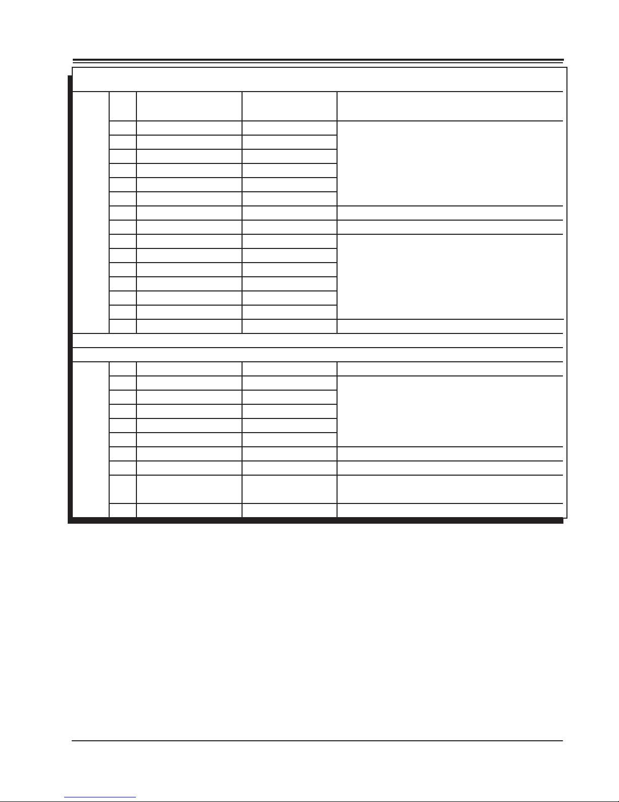
PIN FUNCTION COLOR
2-pin connector connects to Engine Coolant Temp
A ECT BLACK
(ECT) sensor.
B Sensor Ground BROWN
C Coil 2 RED/GREEN
D Coil 4 BROWN/GREEN
E Coil 6 WHITE/BLUE
Connect to Passenger's side coil connector.
(Coils 2-4-6-8)
F Coil 8 VIOLET/BLUE
G 12V Supply PINK
H Battery + RED
J Ground BLACK
16-Pin
K 12V Supply PINK
Connector
Connect to Relay or dedicated fused 30A switch.
Connect to a ground source.
L Coil 7 RED
M Coil 5 GREEN
N Coil 3 BLUE
Connect to Driver's side coil connector.
(Coils 1-3-5-7)
P Coil 1 VIOLET
R Sensor Ground BROWN
S ECT YELLOW
2-pin connector connects to ECT sensor
PIN FUNCTION COLOR
A 12V PINK
B Ground BROWN
C Cam BROWN/WHITE
D Crank ORANGE/YELLOW
E 5V ORANGE
10-Pin
F Factory Use BLACK
Connector
G Not Used
H Step Retard PINK
J Launch Rev Limiter* BLUE
K Tach GRAY
Connect to Cam/Crank pigtail.
Step Retard is activated when 12V is supplied.
When 12V is supplied, the Launch Rev Limiter RPM
value is active. (*Two Step)
Tach output
MSD • WWW.MSDPERFORMANCE.COM • (915) 855-7123 • FAX (915) 857-3344
Page 4
4 INSTALLATION INSTRUCTIONS
CAM/CRANK EXTENSION HARNESSES:
22791 - 24X CRANK / 1X CAM (REAR)
OPTIONAL - 2279 - 24X CRANK / 4X CAM (FRONT)
2278 - 58X CRANK / 4X CAM (FRONT)
22791 - BLACK CRANK SENSOR CONNECTOR
BLACK CAM SENSOR CONNECTOR
2278 - GREY CRANK SENSOR CONNECTOR
BLACK CAM SENSOR CONNECTOR
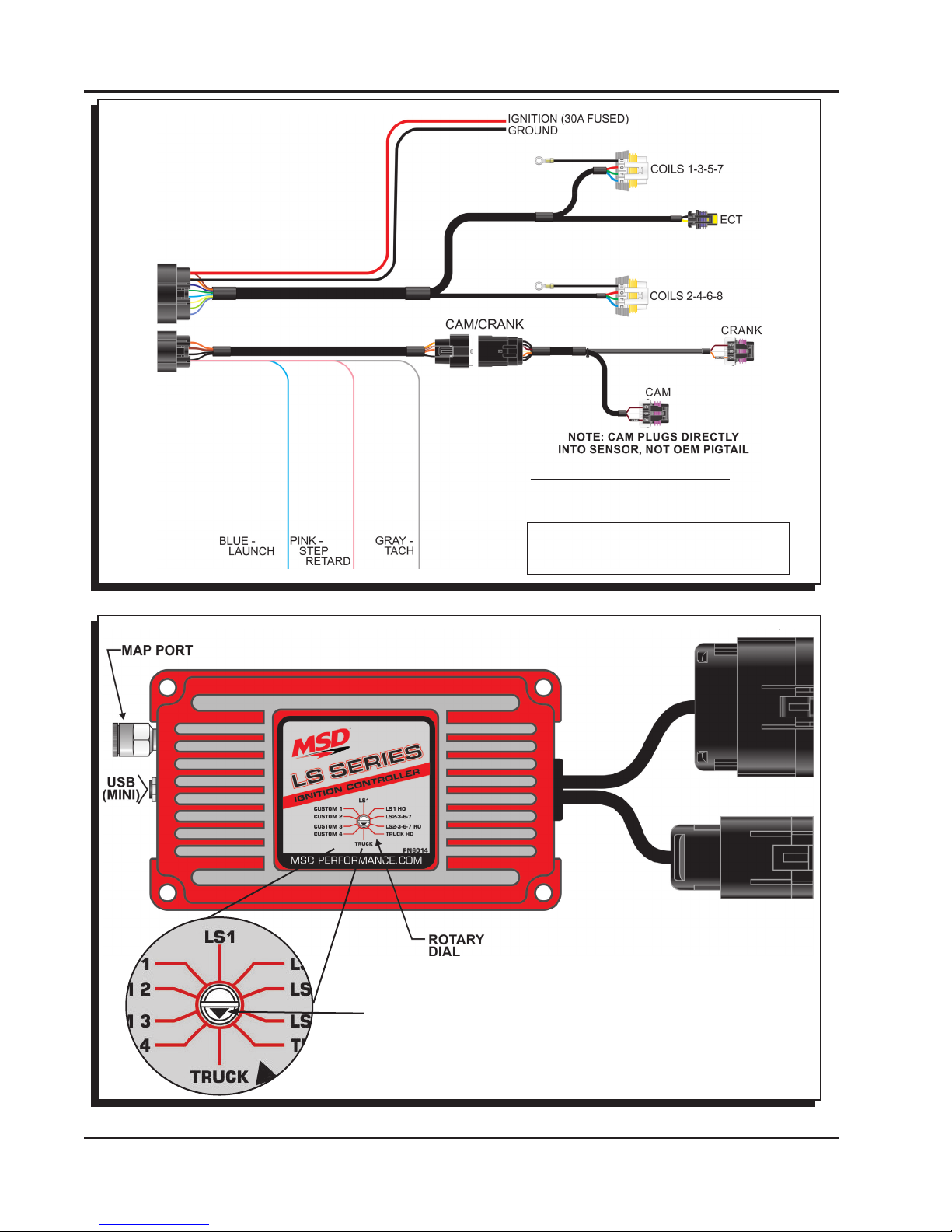
Figure 1 LS Ignition Harness
Figure 2 PN 6014 Ignition Control Timing/Rev LS Series
MSD • WWW.MSDPERFORMANCE.COM • (915) 855-7123 • FAX (915) 857-3344
USE THE ARROW ON
THE SWITCH FOR CURVE
SELECTION.
Page 5

INSTALLATION INSTRUCTIONS 5
Note: The LS Ignition Controller requires a 30 Amp fused power source.
Do not power the unit directly through the Ignition Key switch.
Figure 3 Recommended Relay Set-Up
MOUNTING
The LS Ignition must be mounted in a sturdy, dry location and not exposed to extreme heat. It
should be mounted using the included rubber isolators to limit excessive vibration. The unit is fully
potted, but should not be immersed or subjected to direct spray from a power washer.
MSDView
The MSDView software allows editing of the rst four timing tabs, as well as turning features on/off
and setting up and retrieving data logs. The following information gives a brief explanation of each
function or feature in the system and the settings that control them. While using the software, you
can mouse over each item for a brief on-screen explanation.
Note: Make sure MSDView is installed on the PC prior to connecting the LS Ignition Controller.
INSTALLATION OF THE MSDVIEW SOFTWARE
1. Insert the installation Flashdrive into available USB port.
2. Locate the ‘autorun.exe’ le on the Flashdrive.
3. Click on “Install MSD View Software”. Click ‘Yes’ when asked ‘Do you want the following program
to make changes to this computer?’.
4. Click ‘Next’ in the ‘Setup - MSD View’ window.
Accept the License Agreement and click ‘Next’.
Choose to accept the desktop icon then click ‘Install’.
Click ‘Finish’ to run application.
5. Connect the LS Controller via USB and wait for it to be listed in the product window..
It will be listed in the product window. Select the LS Controller by highlighting the line or checking
the box and clicking the ‘View/Hide’ button.
Note: The rst time the unit is connected, it may prompt for updates to be installed.
MSD • WWW.MSDPERFORMANCE.COM • (915) 855-7123 • FAX (915) 857-3344
Page 6

6 INSTALLATION INSTRUCTIONS
SAVES AND TRANSFERS
Changes made to the LS Ignition Controller via MSDView are in real time. You can create and save
numerous different les to your PC and load them back into the unit for different applications.
The following will go through a general description of the software for the LS Ignition Controller.
OPTIONAL CONNECTIONS
MAP INPUT: This is the Manifold Absolute Pressure sensor that is integral to the unit. It
uses a 1/4” Camozzi tting and is rated at 2.5 Bar. Using it can advance your timing under
engine vacuum and retard it under boost. It is recommended that you use it, but not required
unless you are using forced induction.
COOLANT TEMPERATURE: This will monitor engine temperature. It has the ability to advance the timing while the engine is cold and retard it when it gets hot, helping to prevent
engine damage. It is not required for the unit to function properly and leaving it disconnected
will not advance or retard the timing relative to the base settings. The ECT Diagnostic will
pop up, but will have no ill effect on the controller’s functionality.
PROGRAMMABLE FEATURES, SETTINGS AND DATA ACQUISITION
SETTINGS
These are basic settings that should be congured the rst time the unit is used, but it is not required.
Basic setup can be performed on the bench with just the USB cable connected to the device. No
external power is required.
Maximum Rev Limiter: This is the maximum RPM that the engine can reach before the coils
will not produce spark.
Launch Rev Limiter (Blue Wire): This is the maximum RPM that the engine will reach before
the coils will not produce spark while the launch wire has 12V battery power applied to it.
Latched: When this is “DISABLED”, the two step will activate any time the RPM is at or
above the set Launch Rev Limiter. If it is set to “ENABLED”, the launch rev limiter cannot become active unless the RPM falls below 7/8 of the set RPM. For example: If set
at 4000 RPM and the launch wire is activated, the launch limiter can only come on if the
RPM falls below 3500. This prevents accidental activation while at high RPM (such as a
faulty launch switch activating or activating it with the clutch during the run).
Coil Type: This selects the dwell or charge time of the coils. Choose “AUTO” if unsure.
Auto – The controller will automatically match the coil dwell to the crankshaft reluctor wheel
used.
LS1 – This sets the dwell time of the LS1/6 coils.
LS2/3/7 – This sets the dwell time of the LS2/3/7 coils.
Truck – This sets the dwell time of the early truck coils.
Idle Timing Control: This will use timing to help stabilize the idle speed of your motor.
It should be set to “ENABLED” on any motor that also used a computer controlled IAC.
Enabling it will cause idle timing to be dynamic and it may appear to jump around at idle
when using a timing light.
TIMING TABLES
Under this tab, you will nd the timing tables used to control the spark output. The appropriate table
is selected with the rotary dial on the front of the LS Ignition Controller. If connected with MSDView,
you can double check this setting by looking at “Rotary Dial Position” under the monitor tab. The
four “Custom” tables (Custom 1-4) are adjustable by the user while the other six cannot be modied.
The cell values and axes (interval units) can be changed on all four of the Custom tables. For example, if more resolution is desired on the MAP axis in a Naturally Aspirated application, the interval
units can be adjusted such that the maximum value does not exceed local atmospheric pressure.
The axes on Custom tables 2-4 are linked, so changing one will change all of them. The Custom 1
axes are unique and can be changed independently of the Custom 2-4 axes.
MSD • WWW.MSDPERFORMANCE.COM • (915) 855-7123 • FAX (915) 857-3344
Page 7

INSTALLATION INSTRUCTIONS 7
CUSTOM 1: This tab contains two sub tabs with plots that are similar to MSD PN6010/
PN6012 ignition controllers. The “Engine Speed” tab is similar to springs and weights that
would normally be found in a distributor. Set the base timing at your idle RPM and draw
Figure 4 Custom Timing Table 1
the advance curve as a normal distributor would. The “MAP” table represents a vacuum
advance canister as well as a boost retard. Under a vacuum, it should advance the timing
(positive values) and under boost it should retard values (negative numbers).
CUSTOM 2-4: These tabs are standard 3-D timing tables. The ignition timing will corre-
spond to the value in the cell (the applicable cell being dened by RPM and engine load).
TRUCK: This tab is a timing table to be used on 4.8, 5.3 and 6.0L motors with low octane
fuel.
LS1: This tab is a timing table to be used on a LS1 with low octane fuel.
LS2-3-6-7: This tab is a timing table to be used on a LS2-3-6-7 or 6.2L truck motor with low
octane fuel.
MSD • WWW.MSDPERFORMANCE.COM • (915) 855-7123 • FAX (915) 857-3344
Page 8

8 INSTALLATION INSTRUCTIONS
Figure 5 Timing Tables LS1
HO Tables: These tabs are similar to the regular tables, but have 4-5 more degrees of timing
added in the wide open throttle areas. These should only be used while using high octane
fuel (91-93 Octane).
Note: The timing output from the selected table will be modied by the “TEMPERATURE” correction
as well as the “INDIVIDUAL CYLINDER” timing. The sum of all these values is the nal timing
to the engine.
INDIVIDUAL CYLINDER
These tables control individual cylinder timing. Each CYL # is the actual cylinder number of the engine. Positive values advance the timing and negative values retard the timing. The axes are load
and RPM and are shared with the main custom timing tables (Custom 1-4). If the axis values are
changed in these tables, they will also change in the custom timing tables.
TEMPERATURE
Running an engine coolant temp sensor is not required, but recommended for optimum operation
and engine protection. When the coolant temperature is high, the engine can generally not withstand quite as much timing as when the temperature is low. The default graph is a little more aggressive than in an OEM application, but should work well. If the sensor is not installed or is faulted
(shorted or open) the temperature in the graph will default to 50C (122F) so the numbers surrounding
50C should be left at 0.
Note: The Timing vs Temperature table values are based on the use of the stock LS GM coolant
temp sensor. Do not use a different sensor unless you know the calibration is the same.
STEP RETARD (PINK WIRE)
The “Step Retard” (nitrous) input, will retard the ignition timing when it is activated with +12V power.
It is helpful if you are using a power adder and need to retard the timing while it is active. The following describes how the activation/deactivation works:
TOTAL RETARD: The maximum amount of timing that will be removed after the “ON Ramp
Time” has been passed.
MSD • WWW.MSDPERFORMANCE.COM • (915) 855-7123 • FAX (915) 857-3344
Page 9

INSTALLATION INSTRUCTIONS 9
MINIMUM ENGINE SPEED: This is the minimum engine speed that must be met to retard
the timing. If the “Step Retard” wire is activated below this RPM, it will have no effect and
will not retard the timing. Set this at 0 (zero) if you want the step retard to be active regard-
less of engine RPM.
ON RAMP TIME: The time that it will take to reach the full “Total Retard”. This will allow for
a softer timing retard over time. For example, if you have 10 degrees of Total Retard and
a 1 second ramp time, the controller will retard 1 degree every 0.1 seconds until the full 10
degrees of timing has been pulled out. This timer will not begin until the “Minimum Engine
Speed” is met. Setting On Ramp Time to 0 (zero) will cause an immediate timing retard cor-
responding to the Total Retard.
OFF DELAY: The time the Total Retard remains in effect after the “Step Retard” is deacti-
vated. This can ensure that the intake manifold is void of residual nitrous. This will also delay
the “Off Ramp Time” from starting - meaning that it is additive with respect to the Off Ramp
Time
OFF RAMP TIME: This will decay the effect of the Total Retard - effectively ramping timing
back into the motor instead of removing it instantaneously. Timing will start ramping back in
after the “Off Delay” has expired.
LAUNCH RETARD
The LAUNCH RETARD is used to set the ignition timing during the 10 seconds after the launch wire
is released. It can be helpful in optimizing traction immediately after launch. The Time From Launch
is a monitor item and it is used by the LAUNCH RETARD table.
MSD • WWW.MSDPERFORMANCE.COM • (915) 855-7123 • FAX (915) 857-3344
Figure 6 Launch Retard.
Page 10

10 INSTALLATION INSTRUCTIONS
DATA ACQUISITION
The data recorder on the LS Ignition system is a programmable 8MB storage system. It is meant to
be a recording device to observe RPM, timing, input activations and a number of other different parameters while racing down the track. Once the memory is full, the system will stop recording data
until the user deletes some of the recordings.
SETTINGS
DATA ACQUISITION: Master Enable/Disable switch
START RECORDING ABOVE: The engine speed must be greater than this to begin re-
cording.
ACTIVATE WITH LAUNCH INPUT: If this is enabled, recordings will not start unless the
“Launch” wire is activated. If it is disabled, recordings can start whenever the RPM
conditions are met.
STOP RECORDING BELOW: If the engine speed falls below this, the recording will stop.
MAX RECORDING TIME: This is the longest any single recording can be. If the time is
expired and all other conditions are still met a new recording will automatically begin.
CHANNELS
CHANNEL Description
ENGINE SPEED The Speed of the motor in RPM
IGNITION TIMING Ignition timing referenced to Top Dead Center (TDC)
MAP The Intake Manifold Absolute Pressure in kPa or PSIA
LAUNCH Launch wire: activated = 1; not activated = 0
STEP RETARD Step Retard wire: activated = 1; not activated = 0
ECT Engine Coolant Temperature. It will show -40°C if not connected, but the
controller will default it to 50°C in the temperature timing control
IGNITION VOLTAGE The voltage being supplied to the unit and the coils. It is important that it
remains over 12V to supply proper power to them.
MAP FAULT Indicates the MAP sensor is open or shorted
BATTERY FAULT Activates if voltage drops below 9V or goes above 18V
CAM FAULT Indicates a problem with the camshaft position sensor (CMP). It will acti-
vate if RPM is detected but no cam sensor signal is detected
CRANK FAULT Indicates a camshaft sensor (CMP) signal is detected, but no engine speed
is detected - likely resulting from a Crankshaft Position Sensor (CKP) fault
Note: The system has a limit of 10 minutes of recording every time the Data Acquisition is en-
abled; that includes the initial enable at power up. After the limit is reached, the user must
disable and re-enable the Data Acquisition in order for the system to continue recording.
MONITORS
MONITORS Description
ROTARY DIAL POSITION Indicates which timing table is selected
ENGINE SPEED Engine speed in RPM
IGNITION TIMING Ignition timing referenced to Top Dead Center (TDC)
MAP Intake Manifold Absolute Pressure in kPa or PSIA
LAUNCH INPUT Launch Wire (blue) status (active or inactive)
STEP RETARD INPUT Step Retard (nitrous) status (active or inactive)
RUN TIME The length of time the engine has been running (resets with every
power on cycle)
MSD • WWW.MSDPERFORMANCE.COM • (915) 855-7123 • FAX (915) 857-3344
Page 11

INSTALLATION INSTRUCTIONS 11
REV LIMIT SOURCE Indicates which source will be limiting the motor . It will be Key Off
when connected via USB, Launch when the launch wire is activated
or Maximum any other time.
IGNITION VOLTAGE This is the voltage being supplied to the unit. This is also the voltage
being supplied to the coils - so it is important that it remains over 12V
to supply proper power to them.
ENGINE COOLANT This is the engine coolant temperature in Celsius or Fahrenheit. It will
TEMPERATURE display -40°C if the sensor is not connected or open and 130°C if it
is shorted.
RECORDINGS Number of recordings stored on the device
STORAGE SPACE Amount of free storage space for the recordings
RECORDING Indicates if the unit is currently recording a data le
ROTARY DIAL SELECT Indicates which timing table is selected with the rotary dial and will
be used for timing control.
TIME FROM LAUNCH Indicates the length of time since the Launch Input was de-activated.
Used for Launch Retard.
ALERTS
FAULTS Description/Cause
MAP SENSOR FAULT MAP sensor problem (open or shorted)
BATTERY Activates if voltage drops below 9V or goes above 18V
ECT SENSOR Displays -40°C if temp sensor is not connected; the controller will
default it to 50°C in the temperature timing control table
CAM FAULT RPM is detected but no cam sensor signal is present
CRANK FAULT Camshaft sensor signal is present, but no engine speed is detected
EEPROM READ ERROR EEPROM data corrupted
EEPROM WRITE ERROR Error writing to EEPROM
FLASH READ ERROR Flash data corrupted
FLASH WRITE ERROR Error writing to ash
FLASH FULL The ash is out of memory. Data acquisition is stopped. The user
needs to delete recordings
DATA ACQUISITION The data acquisition buffer is 90% full
BUFFER WARNING
DATA ACQUISITION The data acquisition buffer is full
BUFFER FULL
MSD • WWW.MSDPERFORMANCE.COM • (915) 855-7123 • FAX (915) 857-3344
Page 12

12 INSTALLATION INSTRUCTIONS
TECH NOTES
_________________________________________________________________________________________________________________________
_________________________________________________________________________________________________________________________
_________________________________________________________________________________________________________________________
_________________________________________________________________________________________________________________________
_________________________________________________________________________________________________________________________
_________________________________________________________________________________________________________________________
_________________________________________________________________________________________________________________________
_________________________________________________________________________________________________________________________
_________________________________________________________________________________________________________________________
_________________________________________________________________________________________________________________________
_________________________________________________________________________________________________________________________
_________________________________________________________________________________________________________________________
_________________________________________________________________________________________________________________________
_________________________________________________________________________________________________________________________
_________________________________________________________________________________________________________________________
_________________________________________________________________________________________________________________________
_________________________________________________________________________________________________________________________
_________________________________________________________________________________________________________________________
Service
In case of malfunction, this MSD component will be repaired free of charge according to the terms of the warranty.
When returning MSD components for warranty service, Proof of Purchase must be supplied for verication. After
the warranty period has expired, repair service is based on a minimum and maximum fee.
All returns must have a Return Material Authorization (RMA) number issued to them before
being returned. To obtain an RMA number please contact MSD Customer Service at 1 (888) MSD-7859 or visit
our website at www.msdperformance.com/rma to automatically obtain a number and shipping information.
When returning the unit for repair, leave all wires at the length in which you have them installed. Be sure to include
a detailed account of any problems experienced, and what components and accessories are installed on the vehicle.
The repaired unit will be returned as soon as possible using Ground shipping methods (ground shipping is covered
by warranty). For more information, call MSD at (915) 855-7123. MSD technicians are available from 7:00 a.m. to
5:00 p.m. Monday - Friday (mountain time).
Limited Warranty
MSD warrants this product to be free from defects in material and workmanship under its intended normal use*,
when properly installed and purchased from an authorized MSD dealer, for a period of one year from the date of
the original purchase. This warranty is void for any products purchased through auction websites. If found to be
defective as mentioned above, it will be repaired or replaced at the option of MSD. Any item that is covered under
this warranty will be returned free of charge using Ground shipping methods.
This shall constitute the sole remedy of the purchaser and the sole liability of MSD. To the extent permitted by
law, the foregoing is exclusive and in lieu of all other warranties or representation whether expressed or implied,
including any implied warranty of merchantability or tness. In no event shall MSD or its suppliers be liable for special
or consequential damages.
*Intended normal use means that this item is being used as was originally intended and for the original application
as sold by MSD. Any modications to this item or if it is used on an application other than what MSD markets the
product, the warranty will be void. It is the sole responsibility of the customer to determine that this item will work
for the application they are intending. MSD will accept no liability for custom applications.
MSD • WWW.MSDPERFORMANCE.COM • (915) 857-5200 • FAX (915) 857-3344
FRM 33798 Created 07/16
© 2016 MSD LLC
 Loading...