

Page 1
MSD DynaForce High Speed Starter
Chrysler 318-440 Engines, PN 50982
ONLINE PRODUCT REGISTRATION: Register your MSD product online. Registering your product will help
if there is ever a warranty issue with your product and helps the MSD R&D team create new products that
you ask for! Go to www.msdperformance.com/registration.
IMPORTANT: Proper installation of the DynaForce Starter is important to the overall operation. Correct alignment
of the starter pinion with the ring gear is needed to achieve the best operation and longevity from
your starter. Please read the instructions before attempting the installation.
Parts Included:
1 - Starter 1 - Shim Ring 1 - Outer Shim
WARNING: Before installing the DynaForce Starter disconnect the battery cables. When disconnecting
the battery cables, always remove the Negative (-) cable first and install it last.
Thank you for purchasing the DynaForce High Speed Starter from MSD. Thanks to special gearing
and other design features, the High Speed starter spins 25% faster than our traditional DynaForce
starters. This extra speed is ideal for engines with magnetos or blown alcohol. Please be sure to read,
understand, and follow the instructions prior to installation so that everything goes smoothly and the
engine starts reliably time after time.
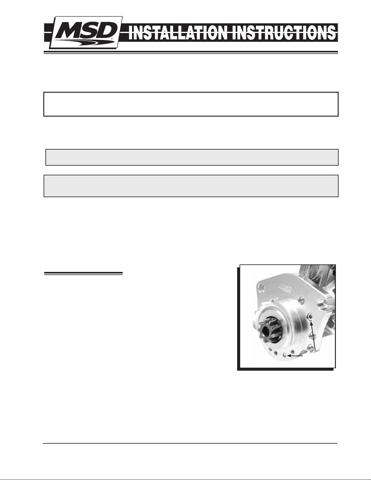
INSTALLATION
1. Make sure the starter mounting surface is clean and smooth.
2. Mount the starter and check that the position of the solenoid is
away from direct heat sources and other components. If there
are clearance problems, the starter housing can be rotated to
move the location of the solenoid. This is done by removing
the three bolts on the mounting block and repositioning the
starter motor (Figure 1).
CLOCKING
LOCATIONS
Figure 1 Clocking the Starter
for Clearance.
M S D • W W W . M S D P E R F O R M A N C E . C O M • ( 9 1 5 ) 8 5 7 - 5 2 0 0 • F A X ( 9 1 5 ) 8 5 7 - 3 3 4 4
Page 2
2 INSTALLATION INSTRUCTIONS
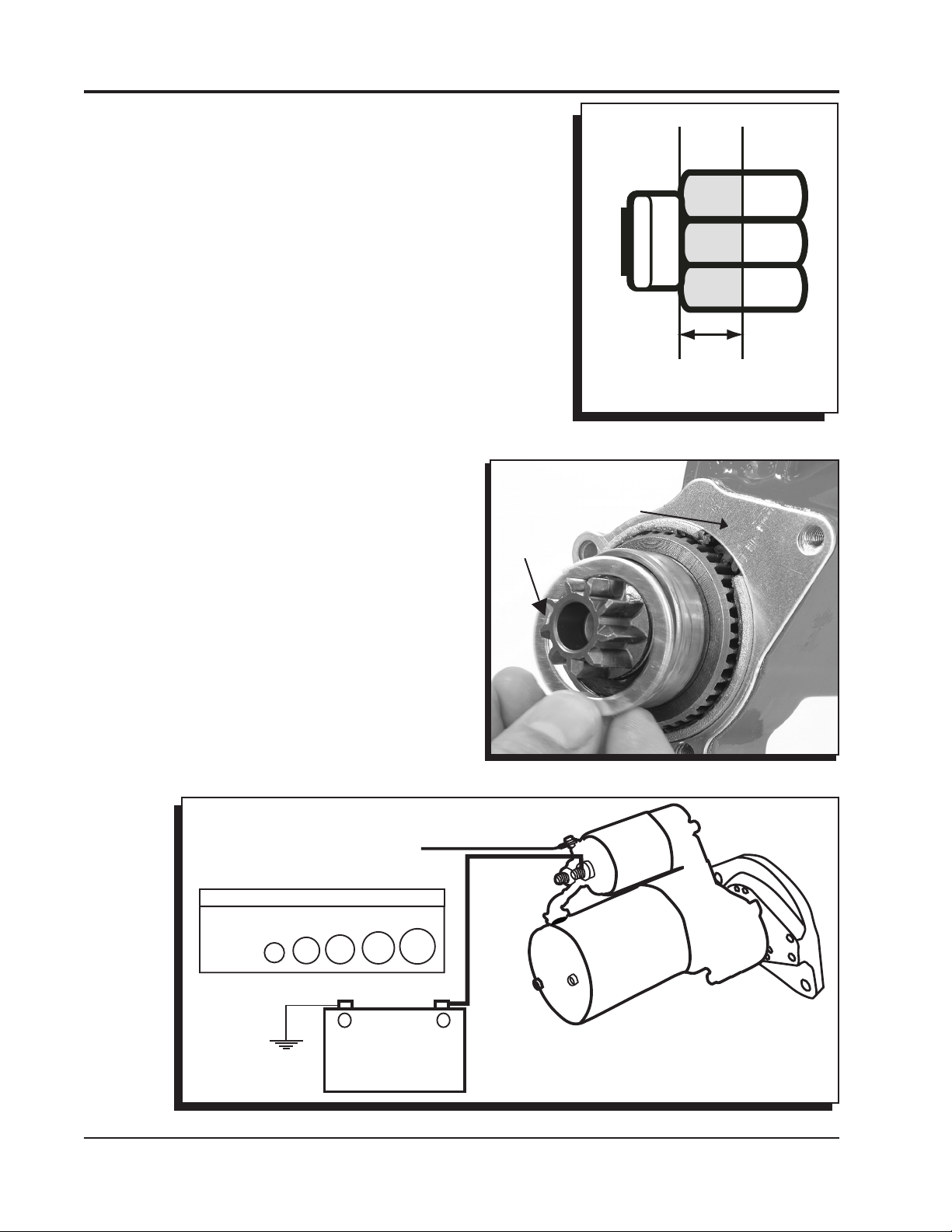
3. After confirming clearances and position of the solenoid, it is
time to check the pinion engagement to the ring gear. This
is done by gently prying out the pinion gear to the ring gear.
The pinion should engage by 1/4" minimum and 3/8" max on
to the ring gear (Figure 2)
• If there is not enough clearance, you will need to install the
supplied shim kit by removing the mounting block (Figure
3). If the pinion gear engages too far onto the ring gear,
there will be issues with disengagement. MSD supplies a
shim ring to move the pinion 0.060". Remove the mounting
block and place the small shim ring in the bearing bore and
install the outer shim on the support housing. Reinstall the
mounting block. This will move the pinion gear into the starter
approximately 0.060".
4. With the starter mounted and gear engagement confirmed,
it is time to connect the wires. The switch wire that connects
to the solenoid should be at least 12-gauge (Figure 4). For
alternative wiring to incorporate the factory remote solenoid,
THE CORRECT PINION DEPTH
SHOULD MEASURE 1/4” to 3/8”.
Figure 2 Pinion Gear Pattern.
See Figure 5.
5. Attach the battery cable. The gauge of the battery
cable depends on its length. Using the proper
gauge wire is important to the operation of the
starter. Both the positive and ground wires must
be able to meet the demands of the starter. The
SHIM
RING
INSTALL OUTER
SHIM
chart in Figure 5 shows the recommended sizes.
Be sure to route the wire away from the exhaust
and moving parts of the engine.
6. Connect the battery terminals and start the engine.
IMPORTANT: Never operate a starter for more than
30 seconds at a time without letting it
cool for at least two minutes.
Figure 3 Installing the Pinion Shim Spacers.
12-GAUGE MINIMUM
TO IGNITION
SWITCH
CABLE LENGTH VS. GAUGE
LENGTH
AWG
3’ 5’ 7’ 10’ +10’
00
0
1
2
4
-
BATTERY
+
Figure 4 Wiring the DynaForce High Speed Starter.
M S D • W W W . M S D P E R F O R M A N C E . C O M • ( 9 1 5 ) 8 5 7 - 5 2 0 0 • F A X ( 9 1 5 ) 8 5 7 - 3 3 4 4
Page 3

INSTALLATION INSTRUCTIONS 3
FACTORY REMOTE SOLENOID
SWITCH
-
BATTERY
+
Figure 5 Wiring to Incorporate an External Solenoid.
10-12 GAUGETO IGNITION
INSTALLATION INFO
SLOW CRANKING
The most common cause is due to low input voltage. The battery should be checked, but also inspect
the battery wires, terminals, connections or switches.
DISCONNECT SWITCHES
Most sanctioning bodies require an emergency disconnect switch. Be sure to use a heavy duty switch
that is capable of handling high current. Some starters may pull over 700 amps while cranking. Most
disconnect switches are rated at continuous and intermittent amps. Make sure to use a switch that
exceeds your starting and electrical system requirements.
M S D • W W W . M S D P E R F O R M A N C E . C O M • ( 9 1 5 ) 8 5 7 - 5 2 0 0 • F A X ( 9 1 5 ) 8 5 7 - 3 3 4 4
Page 4
TECH NOTES
_________________________________________________________________________________________________________________________
_________________________________________________________________________________________________________________________
_________________________________________________________________________________________________________________________
_________________________________________________________________________________________________________________________
_________________________________________________________________________________________________________________________
_________________________________________________________________________________________________________________________
_________________________________________________________________________________________________________________________
_________________________________________________________________________________________________________________________
_________________________________________________________________________________________________________________________
_________________________________________________________________________________________________________________________
_________________________________________________________________________________________________________________________
_________________________________________________________________________________________________________________________
_________________________________________________________________________________________________________________________
_________________________________________________________________________________________________________________________
_________________________________________________________________________________________________________________________
_________________________________________________________________________________________________________________________
Service
In case of malfunction, this MSD component will be repaired free of charge according to the terms of the warranty.
When returning MSD components for warranty service, Proof of Purchase must be supplied for verification. After
the warranty period has expired, repair service is based on a minimum and maximum fee.
All returns must have a Return Material Authorization (RMA) number issued to them before
being returned. To obtain an RMA number please contact MSD Customer Service at 1 (888) MSD-7859 or visit
our website at www.msdperformance.com/rma to automatically obtain a number and shipping information.
When returning the unit for repair, leave all wires at the length in which you have them installed. Be sure to include
a detailed account of any problems experienced, and what components and accessories are installed on the vehicle.
The repaired unit will be returned as soon as possible using Ground shipping methods (ground shipping is covered
by warranty). For more information, call MSD at (915) 855-7123. MSD technicians are available from 7:00 a.m. to
5:00 p.m. Monday - Friday (mountain time).
Limited Warranty
MSD warrants this product to be free from defects in material and workmanship under its intended normal use*,
when properly installed and purchased from an authorized MSD dealer, for a period of one year from the date of
the original purchase. This warranty is void for any products purchased through auction websites. If found to be
defective as mentioned above, it will be repaired or replaced at the option of MSD. Any item that is covered under
this warranty will be returned free of charge using Ground shipping methods.
This shall constitute the sole remedy of the purchaser and the sole liability of MSD. To the extent permitted by
law, the foregoing is exclusive and in lieu of all other warranties or representation whether expressed or implied,
including any implied warranty of merchantability or fitness. In no event shall MSD or its suppliers be liable for special
or consequential damages.
*Intended normal use means that this item is being used as was originally intended and for the original application
as sold by MSD. Any modifications to this item or if it is used on an application other than what MSD markets the
product, the warranty will be void. It is the sole responsibility of the customer to determine that this item will work for
the application they are intending. MSD will accept no liability for custom applications.
M S D • W W W . M S D P E R F O R M A N C E . C O M • ( 9 1 5 ) 8 5 7 - 5 2 0 0 • F A X ( 9 1 5 ) 8 5 7 - 3 3 4 4
© 2012 Autotr onic Contro ls Corporat ion
FRM31157 Created 10/12 Printed in U.S.A.
 Loading...