

Page 1
EIF4292
g
GLOBAL GSM SERVICE SUPPORT
FIELD SERVICE BULLETIN
Title: GSM Phoenix V60i -TXVCO Module Defect
Author: Alan King
Released by: EMEA Competency Centre
Date: 17
Number of Pages: 7
Bulletin Ref. No: EI0432
Product: GSM Phoenix V60i
System: GSM
Problem:
During the analysis of the 1
(U350). The customer complains that they are unable to make a call and/or camp onto the network and in
some cases the customer complained of drops calls or poor receive.
Further analysis of faulty TxVCO modules has shown that the issue is due to no Tx output signal at pin 6 of
the TxVCO module. This problem can occur on 900/1800/1900MHz bands and often only affects one band.
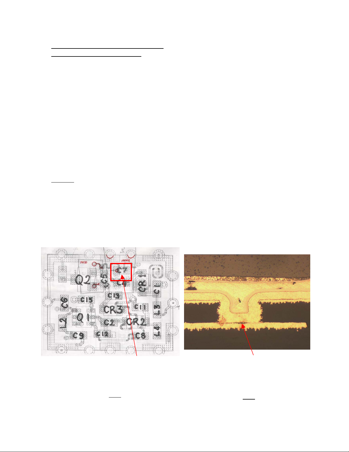
Further root cause analysis of the module has shown this is due to micro-via separation within the TxVCO
module (See Fig 1 & Fig 2).
th
January 2003
st
400 V60i NPI field returns an issue was identified with the TxVCO module
Top view of an open circuit Micro-via at C7
(TxVCO module U350). Open circuits via’s
have also been seen in locations C4, C5, R9
and L5 of the TxVCO module.
1
Fi
MOTOROLA CONFIDENTIAL & PROPRIETARY
The dark region at the center of the via indicates
a poor connection between the plating and the
Layer 2 target land of the TXVCO Module
Fig 2
Page 2
EIF4292
Solution:
TxVCO vendor Ibiden have been provided further samples of this failure mode. Motorola CTE-MFAL
continue to work with vendors Ibiden to ensure that the root cause is fully understood and any required 8D
actions are implemented as soon as possible.
Could I ask that defective TxVCO (U350) modules are collected for further analysis. Please mail
myself in the first instance and I will arrange shipping details mailto:aking@motorola.com
Service Action:
For any V60i units returned for camping issues or call related issues carry out the following tests:
1/ Using the RadioComm tool put the radio into “Suspend mode” and set for a “Psuedo Random carrier
w/midamble 0” and check for a Tx output by putting the spectrum analyzer probe close to the radios
antenna (check for an appropriate o/p according to the table below).
NB. Power o/p measured may vary depending on probe
Channel Tx Frequency Expected o/p at Antenna
062 902.44 MHz Approx 20dBm (PA Level 10)
700 1747.8 MHz Approx 20dBm (PA Level 10)
661 1880 MHz Approx 20dBm (PA Level 10)
Table 1
2/ If the output tests in Table 1 appear to be correct then the issue is unlikely to be related to the TXVCO
module and the unit should continue to be analyzed as normal.
3/ If any of the outputs at the antenna are missing on any of the three bands then follow the proceeding
steps for the affected radio band.
MOTOROLA CONFIDENTIAL & PROPRIETARY
Page 3
EIF4292
No Antenna Output on the 900Mhz Band
a) Open the radio and remove shield SH4.
(NB. It is possible to test without removing shield SH4 however in some cases this can prove difficult
due to limited access)- See fig 4.
b) Check resistance to ground of pins 3 and 6 of Tx VCO module U350 using a DMM. (This test can detect
solder short of those pins to ground). Values should be as follows: Pin 3 to Gnd = ~16K ohms, Pin 6 to Gnd
= ~89.7 ohms. ( If a short to ground is found then the unit should be further analyzed as normal for this
type of failure).
c) Assuming that there are no shorts to ground found in test b), use the RadioComm tool to turn on TX in
suspend mode
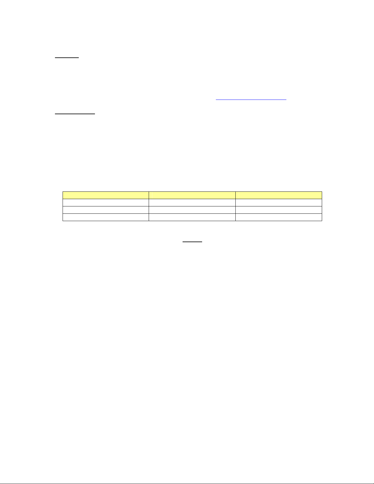
d) Using an oscilloscope check for the following signals at U350 (Expected pin signals are shown below
Fig 3)
e) The TxVCO module U350 is defective if the signals shown in Figure 3 are present but there is no RF
output signal at pin 6 of the TxVCO. (NB. The frequency at pin 6 may vary and will be depend on the
voltage level of pin 3).
f) Confirmed faulty U350 modules should be replaced with part number 4809283D84 and the radio rephased/tested.
1 7 2
6 U350 3
5 10 4
NB. Start frequency of the
spectrum analyzer should
be set to 700 MHz. It is
also suggested to check RF
power level at pin 6 on
working XCVR first, to
make sure that the test
setup is working correctly.
Fig.3
MOTOROLA CONFIDENTIAL & PROPRIETARY
Page 4
EIF4292
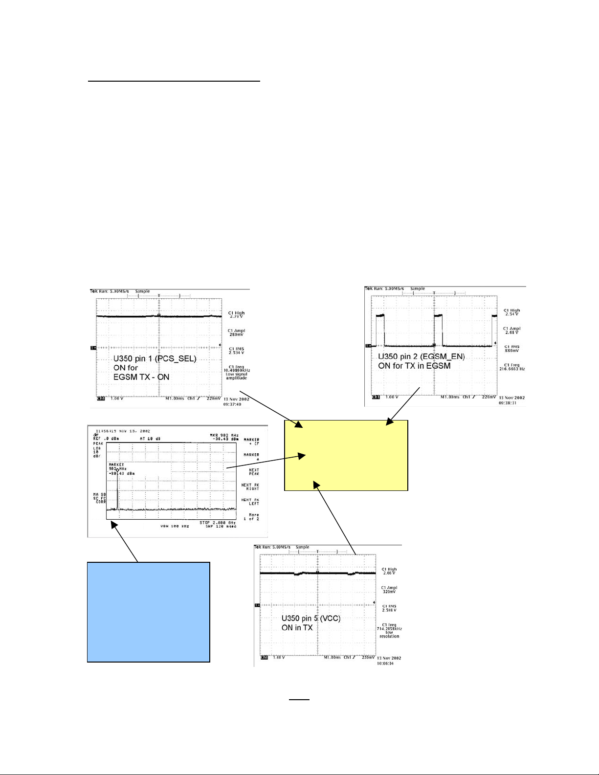
DPCS_EN
C362
NB. These Test Points Can Be Used For Testing All Bands
SF_OUT_F
VCC of VCO
C354
TX_VCO_OUT
SH4
R534 or C530
VT of TX VCO
R351
EGSM_EN
Pin 6 of Q404
TX_VCO_VT
C238
(Can be used if
VT is to
difficult to
N_DCS_SEL
Q405 Pin 2 or 4
(Can be used if
PCS_ SEL is to
difficult to reach)
access)
PCS_SEL
C361 or
pin 1 of U350
Fig4 -PCB
MOTOROLA CONFIDENTIAL & PROPRIETARY
Page 5

EIF4292
No Antenna Output on the 1800Mhz Band
a) Open the radio and remove shield SH4.
(NB. It is possible to test without removing shield SH4 however in some cases this can prove difficult
due to limited access)- See fig 4.
b) Check resistance to ground of pins 3 and 6 of Tx VCO module U350 using a DMM. (This test can detect
solder short of those pins to ground). Values should be as follows: Pin 3 to Gnd = ~16K ohms, Pin 6 to Gnd
= ~89.7 ohms. ( If a short to ground is found then the unit should be further analyzed as normal for this
type of failure).
c) Assuming that there are no shorts to ground found in test b), use the RadioComm tool to turn on TX in
suspend mode
d) Using an oscilloscope check for the following signals at U350 (Expected pin signals are shown below
Fig 5)
e) The TxVCO module U350 is defective if the signals shown in Figure 5 are present but there is no RF
output signal at pin 6 of the TxVCO.
(NB. The frequency at pin 6 may vary and will be depend on the voltage level of pin 3).
f) Confirmed faulty U350 modules should be replaced with part number 4809283D84 and the radio rephased/tested.
NB. Start frequency of the
spectrum analyzer should
be set to 700 MHz. It is
also suggested to check RF
power level at pin 6 on
working XCVR first, to
make sure that the test
setup is working correctly.
1 7 2
6 U350 3
5 10 4
Fig.5
MOTOROLA CONFIDENTIAL & PROPRIETARY
Page 6

EIF4292
No Antenna Output on the 1900Mhz Band
a) Open the radio and remove shield SH4.
(NB. It is possible to test without removing shield SH4 however in some cases this can prove difficult
due to limited access)- See fig 4.
b) Check resistance to ground of pins 3 and 6 of Tx VCO module U350 using a DMM. (This test can detect
solder short of those pins to ground). Values should be as follows: Pin 3 to Gnd = ~16K ohms, Pin 6 to Gnd
= ~89.7 ohms. ( If a short to ground is found then the unit should be further analyzed as normal for this
type of failure).
c) Assuming that there are no shorts to ground found in test b), use the RadioComm tool to turn on TX in
suspend mode
d) Using an oscilloscope check for the following signals at U350 (Expected pin signals are shown below in
Fig 6)
e) The TxVCO module U350 is defective if the signals shown in Figure 6 are present but there is no RF
output signal at pin 6 of the TxVCO.
(NB. The frequency at pin 6 may vary and will be depend on the voltage level of pin 3).
f) Confirmed faulty U350 modules should be replaced with part number 4809283D84 and the radio rephased/tested.
NB. Start frequency of the
spectrum analyzer should
be set to 700 MHz. It is
suggested to check RF
power level at pin 6 on
working XCVR first, to
make sure that the setup is
working.
1 7 2
6 U350 3
5 10 4
Fig.6
MOTOROLA CONFIDENTIAL & PROPRIETARY
Page 7

EIF4292
EPPRS Code Usage
Please ensure that repairs of this type are logged on the EPPRS database as follows:
Confirmed Code: 5 No Rx/Tx
Root Cause Code: 60 Defective Modem IC (SMOC, FIRESTORM, MODEM)
57 Cannot make calls
58 Cannot received calls
59 Phone drops calls during a call
60 Phone drops call when answering or making a call
62 Defective Rx/Tx IC (GIF SYN, MAGIC)
MOTOROLA CONFIDENTIAL & PROPRIETARY
 Loading...