

Page 1
Motorola GmbH, Mobile Devices, CSS Center
Title: Troubleshooting-Guide MotoRAZR maxx V6 Page: 1 / 40
Doc. No: TSG_3G_V6
Version: 1.0
Date: 23.07.2007
Troubleshooting Guide MotoRAZR maxx V6
Level 3
Repair Support Information
© Copyright 2003-2007 Motorola Inc. All Rights reserved.
Motorola internal use
Page 2
Doc. No: TSG_3G_V6
Version: 1.0
Motorola GmbH, Mobile Devices, CSS Center
Date: 23.07.2007
Title: Troubleshooting-Guide MotoRAZR maxx V6 Page: 2 / 40
Revision History
Date Version Comment
2007-07-23 1.0 Initial release of document
Contents
Revision History .......................................................................................................................2
Contents...................................................................................................................................2
Introduction...............................................................................................................................3
Audience...............................................................................................................................3
Requirements .......................................................................................................................3
About this Troubleshooting Guide ........................................................................................3
Related Documents..............................................................................................................3
Basic information on troubleshooting Motorola 3G phones..................................................3
Tools.........................................................................................................................................4
Required Tools .....................................................................................................................4
Additional Tools....................................................................................................................4
Troubleshooting Level 2...........................................................................................................5
No speaker audio..................................................................................................................5
No microphone audio............................................................................................................7
No ring tone/alert function.....................................................................................................8
No vibrator function.............................................................................................................10
No display/-backlight/poor picture quality...........................................................................12
Keypad/ side keys – no function.........................................................................................13
Telephone will not turn on or stay on..................................................................................14
Can’t make voice call/no service ........................................................................................15
Troubleshooting Level3..........................................................................................................16
Audio problems...................................................................................................................16
No speaker audio................................................................................................................16
No microphone audio..........................................................................................................17
No ring tone/alert function...................................................................................................18
No vibrator function.............................................................................................................19
No display/-backlight/poor picture quality...........................................................................20
Flip detect problem.............................................................................................................21
Keypad/side keys – no function/hangs...............................................................................22
On/Off switch not working...................................................................................................23
No keypad backlight ...........................................................................................................24
SIM card – check card/insert SIM.......................................................................................25
TransFlash Memory Card – no function .............................................................................26
No turn on...........................................................................................................................27
Turn off – powers down in standby.....................................................................................29
Battery life short/charging problems/no turn on due to excessive current drain.................29
Does not charge .................................................................................................................30
Invalid Battery.....................................................................................................................31
Battery Thermistor problem................................................................................................32
Accessory detection problem..............................................................................................33
Can’t make voice call/no service ........................................................................................34
No or low TX output power in GSM....................................................................................34
No or low TX output power in WCDMA ..............................................................................36
No RX GSM........................................................................................................................37
No RX WCDMA..................................................................................................................38
Flash procedures....................................................................................................................40
Software update..................................................................................................................40
Recovering Flash Memory in Forced Flash Mode..............................................................40
Repair Support Information
© Copyright 2003-2007 Motorola Inc. All Rights reserved.
Motorola internal use
Page 3

Doc. No: TSG_3G_V6
Version: 1.0
Motorola GmbH, Mobile Devices, CSS Center
Date: 23.07.2007
Title: Troubleshooting-Guide MotoRAZR maxx V6 Page: 3 / 40
Introduction
Audience
This document aids service personnel in testing and repairing V6 telephones. Service
personnel should be familiar with electronic assembly, testing, and troubleshooting methods,
and with the operation and use of associated test equipment.
Requirements
Follow the current Technical Requirements for servicing Motorola products as described in
Requirement List for Motorola Authorized Service Centers.
the
About this Troubleshooting Guide
This document was created to assist analyzers troubleshooting problems on Motorola 3G
Phones. All information was collected during the repair in the Repair Entitlement Group
Flensburg.
Related Documents
V6 Level 1&2 Service Manual
V6 mechanical Overview
V6 Disassembly Video
V6 Assembly Video
Basic information on troubleshooting Motorola 3G phones
Make sure on any problem, that it is not a software related one by simply doing a 1FF reflash
with a Master Reset/Master Clear afterwards. In many cases a simple Master Reset can
already fix the problem.
Make sure all contacts are clean.
Use newest approved Software.
Do a visual inspection on customer abuse/liquid contamination.
Repair Support Information
© Copyright 2003-2007 Motorola Inc. All Rights reserved.
Motorola internal use
Page 4

Doc. No: TSG_3G_V6
Version: 1.0
Motorola GmbH, Mobile Devices, CSS Center
Date: 23.07.2007
Title: Troubleshooting-Guide MotoRAZR maxx V6 Page: 4 / 40
Tools
Required Tools
Main Lens Press Fixture http://md-service.corp.mot.com/Bulletins/PPreview.aspx?Key=1827
Keypad Tab Bent Fixture http://md-service.corp.mot.com/Bulletins/PPreview.aspx?Key=1830
Additional Tools
Following passive and active cooling devices are available at
V6 Shield Direktkühlung POP-Processor
Artikelnummer: 946071
www.multitast.de.
Figure 1
Figure 2
V6 Shield Direktkühlung Atlas
Artikelnummer: 946072
V6 Teflon shield-Set (3pcs)
Artikelnummer: 946073
Figure 3
Repair Support Information
© Copyright 2003-2007 Motorola Inc. All Rights reserved.
Motorola internal use
Page 5
Doc. No: TSG_3G_V6
Version: 1.0
Motorola GmbH, Mobile Devices, CSS Center
Date: 23.07.2007
Title: Troubleshooting-Guide MotoRAZR maxx V6 Page: 5 / 40
Troubleshooting Level 2
No speaker audio
Probable cause:
a) Transceiver board assembly defective
Verification: Temporarily replace the flip assembly with a known good flip assembly. If the
fault has not been cleared, it is because of a defective transceiver board assembly. Forward
to an authorized Level 3 Service Center or proceed to
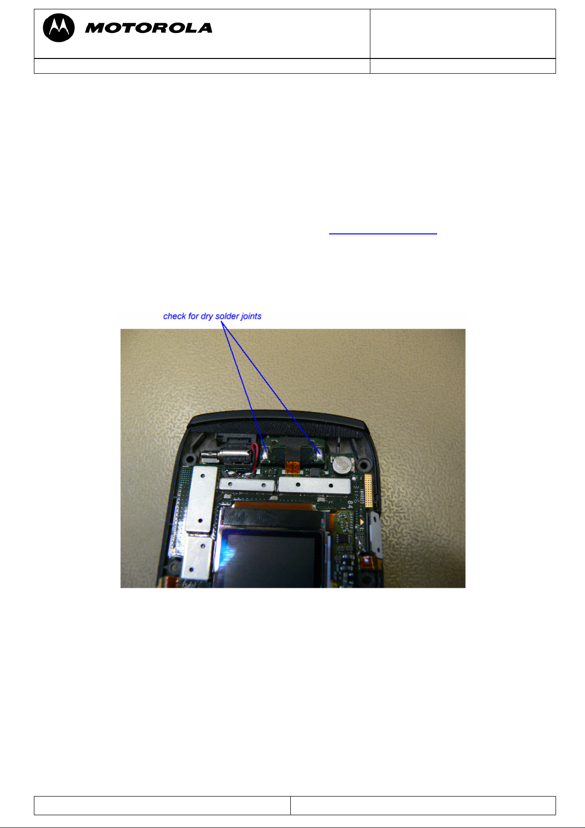
b) Speaker bad soldered/defective
Remove flip cover and visually inspect soldered contacts at speaker. If not ok, resolder
speaker. Otherwise replace speaker with a new one.
level 3 troubleshooting.
Figure 4
c) Keyboard flex assy defective
Remove flip cover. Unseat the display module assembly flex connector from its socket and
temporarily connect the display module assembly and transceiver board assembly with a
known good keyboard flex assy as shown on Figure 3. Check speaker function by turning on
a 1 kHz test tone via RepairStudio/Radiocomm. If the fault has been cleared, reassemble flip
assy with new keyboard flex assy.
Repair Support Information
© Copyright 2003-2007 Motorola Inc. All Rights reserved.
Motorola internal use
Page 6

Doc. No: TSG_3G_V6
Version: 1.0
Motorola GmbH, Mobile Devices, CSS Center
Date: 23.07.2007
Title: Troubleshooting-Guide MotoRAZR maxx V6 Page: 6 / 40
Figure 5
d) Flip PCB defective
If the fault has not been cleared with one of the previous steps a), b) or c), it is most likely a
defective Flip PCB.
Repair Support Information
© Copyright 2003-2007 Motorola Inc. All Rights reserved.
Motorola internal use
Page 7
Doc. No: TSG_3G_V6
Version: 1.0
Motorola GmbH, Mobile Devices, CSS Center
Date: 23.07.2007
Title: Troubleshooting-Guide MotoRAZR maxx V6 Page: 7 / 40
No microphone audio
Probable cause:
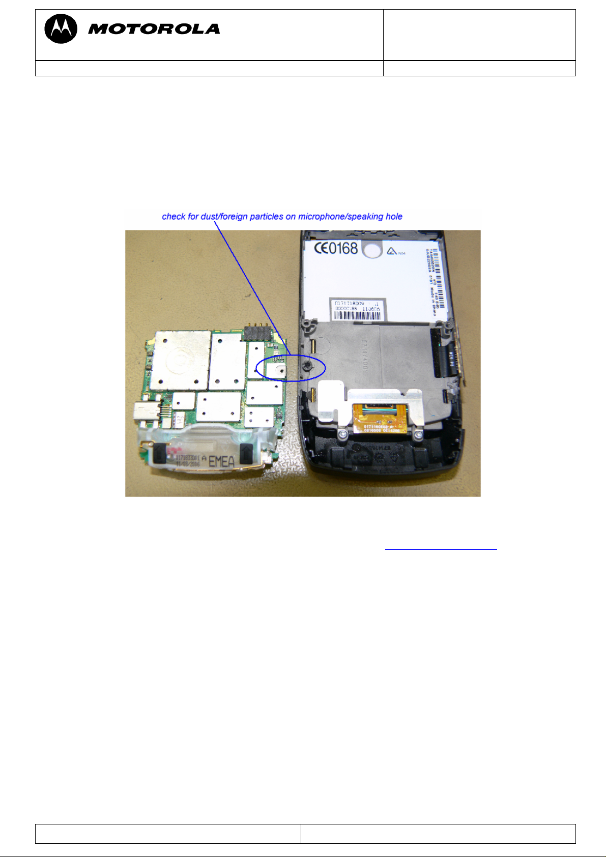
a) Dust/Foreign particles on microphone
Gain access to the transceiver board assembly and make sure that no dust/foreign particles
are on microphone/speaking hole in flip assembly
Figure 6
b) Transceiver board assembly defective
Forward to an authorized Level 3 Service Center or proceed to
level 3 troubleshooting.
Repair Support Information
© Copyright 2003-2007 Motorola Inc. All Rights reserved.
Motorola internal use
Page 8
Doc. No: TSG_3G_V6
Version: 1.0
Motorola GmbH, Mobile Devices, CSS Center
Date: 23.07.2007
Title: Troubleshooting-Guide MotoRAZR maxx V6 Page: 8 / 40
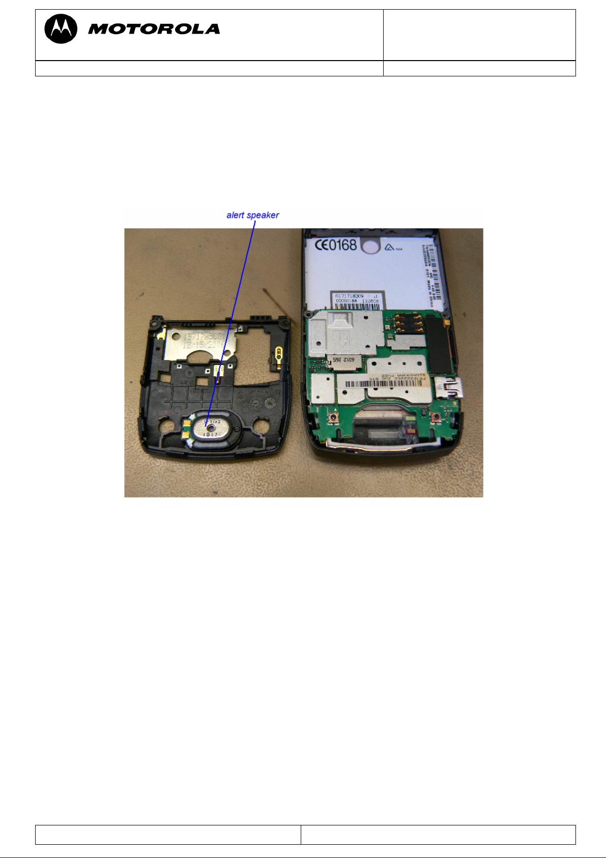
No ring tone/alert function
Probable cause:
a) Faulty alert speaker (part of rear housing assy)
Verification: Remove rear housing assy and temporarily replace the rear housing assy with a
known good one. If the fault has been cleared, reassemble with new rear housing assy.
Figure 7
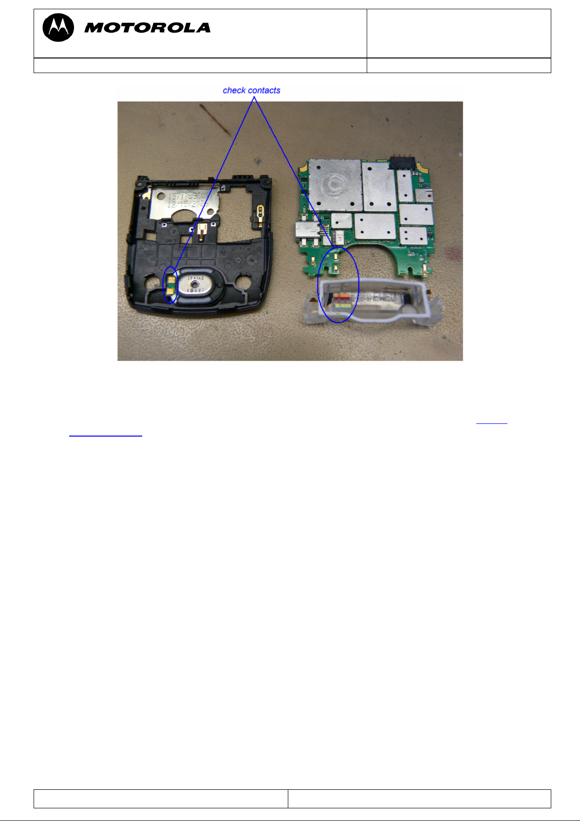
b) Faulty connection transceiver board assembly to alert speaker
Remove antenna assembly and check contacts. Temporarily replace antenna assy with a
known good one. If the fault has been cleared, reassemble with a new antenna assy.
Repair Support Information
© Copyright 2003-2007 Motorola Inc. All Rights reserved.
Motorola internal use
Page 9
Doc. No: TSG_3G_V6
Version: 1.0
Motorola GmbH, Mobile Devices, CSS Center
Date: 23.07.2007
Title: Troubleshooting-Guide MotoRAZR maxx V6 Page: 9 / 40
Figure 8
c) Faulty transceiver board assembly
Verification: temporarily replace the transceiver board assembly with a known good one. f the
fault has been cleared, forward to an authorized Level 3 Service Center or proceed to
level 3
troubleshooting.
Repair Support Information
© Copyright 2003-2007 Motorola Inc. All Rights reserved.
Motorola internal use
Page 10
Doc. No: TSG_3G_V6
Version: 1.0
Motorola GmbH, Mobile Devices, CSS Center
Date: 23.07.2007
Title: Troubleshooting-Guide MotoRAZR maxx V6 Page: 10 / 40
No vibrator function
Probable cause:
a) Transceiver board assembly defective
Verification: Temporarily replace the flip assembly with a known good flip assembly. If the
fault has not been cleared, it is because of a defective transceiver board assembly. Forward
to an authorized Level 3 Service Center or proceed to
level 3 troubleshooting.
b) Vibrator bad soldered/defective
Remove flip cover and visually inspect soldered contacts at vibrator. If not ok, resolder
vibrator. Otherwise replace vibrator with a new one.
c) Keyboard flex assy defective
Remove flip cover. Unseat the display module assembly flex connector from its socket and
temporarily connect the display module assembly and transceiver board assembly with a
known good keyboard flex assy as shown on Figure 8. Check vibrator function by turning on
vibrator via RepairStudio/Radiocomm. If the fault has been cleared, reassemble flip assy with
new keyboard flex assy.
Repair Support Information
Figure 9
© Copyright 2003-2007 Motorola Inc. All Rights reserved.
Motorola internal use
Page 11
Doc. No: TSG_3G_V6
Version: 1.0
Motorola GmbH, Mobile Devices, CSS Center
Date: 23.07.2007
Title: Troubleshooting-Guide MotoRAZR maxx V6 Page: 11 / 40
Figure 10
d) Flip PCB defective
If the fault has not been cleared with one of the previous steps a), b) or c), it is most likely a
defective Flip PCB.
Repair Support Information
© Copyright 2003-2007 Motorola Inc. All Rights reserved.
Motorola internal use
Page 12

Doc. No: TSG_3G_V6
Version: 1.0
Motorola GmbH, Mobile Devices, CSS Center
Date: 23.07.2007
Title: Troubleshooting-Guide MotoRAZR maxx V6 Page: 12 / 40
No display/-backlight/poor picture quality
Probable cause:
a) Transceiver board assembly defective
Verification: Temporarily replace the flip assembly with a known good flip assembly. If the
fault has not been cleared, it is because of a defective transceiver board assembly. Forward
to an authorized Level 3 Service Center or proceed to
level 3 troubleshooting.
b) Transceiver board connections faulty
Remove rear housing assy from unit and check general condition of flexible printed cable
(keyboard flex assy). If the flex is good, check that the flex connector is fully pressed down.
c) Keyboard flex assy defective
Remove flip cover. Unseat the display module assembly flex connector from its socket and
temporarily connect the display module assembly and transceiver board assembly with a
known good keyboard flex assy as shown on Figure 9. Check function of both displays. If the
fault has been cleared, reassemble flip assy with new keyboard flex assy.
Figure 11
d) Main display or CLI display faulty
Check function of both displays. If just one of them has no function, most likely that display
itself is defective
e) Flip PCB defective
If the fault has not been cleared with one of the previous steps a), b), c) or d), it is most likely
a defective Flip PCB.
Repair Support Information
© Copyright 2003-2007 Motorola Inc. All Rights reserved.
Motorola internal use
Page 13
Doc. No: TSG_3G_V6
Version: 1.0
Motorola GmbH, Mobile Devices, CSS Center
Date: 23.07.2007
Title: Troubleshooting-Guide MotoRAZR maxx V6 Page: 13 / 40
Keypad/ side keys – no function
Probable cause:
a) Transceiver board assembly defective
Verification: Temporarily replace the flip assembly with a known good flip assembly. If the
fault has not been cleared, it is because of a defective transceiver board assembly. Forward
to an authorized level 3 service center or proceed to
level 3 troubleshooting.
b) Keyboard flex assy defective
Remove flip cover. Unseat the display module assembly flex connector from its socket and
temporarily connect the display module assembly and transceiver board assembly with a
known good keyboard flex assy as shown on Figure 10. Check function of keyboard. If the
fault has been cleared, reassemble flip assy with new keyboard flex assy.
c) Flip PCB defective
If the fault has not been cleared with one of the previous steps a) or b), it is most likely a
defective Flip PCB.
Repair Support Information
Figure 12
© Copyright 2003-2007 Motorola Inc. All Rights reserved.
Motorola internal use
Page 14

Doc. No: TSG_3G_V6
Version: 1.0
Motorola GmbH, Mobile Devices, CSS Center
Date: 23.07.2007
Title: Troubleshooting-Guide MotoRAZR maxx V6 Page: 14 / 40
Telephone will not turn on or stay on
Probable cause:
a) Battery either discharged or defective
Try to switch on telephone with a known good battery. If the telephone turns on, make sure
that the phone is able to charge the battery. If ok, replace battery with a new one. If the
phone does not charge the battery, forward to Level 3 Service Center or proceed to
troubleshooting.
b) Battery contacts open or misaligned
Visually inspect the battery connectors on both the battery and the telephone. Realign and
clean contacts, if necessary. For battery connector replacement forward to an authorized
Level 3 Service Center.
level 3
c) Keyboard flex assy defective
If the telephone turns on via EMU USB cable and is unable to power down after pressing the
ON/OFF button, it could be because of a faulty keyboard flex assy. For verification
reassemble the unit with a known good flip assy. If the fault has been cleared, replace
keyboard flex assy with a new one.
d) Software corrupt
If the telephone shows a bootloader menu as shown in Figure 10 or is able to enter the
bootloader menu by holding “*” + “#” keys while turning on, the phone software possibly can
be recovered by a 1FF software reflash. Proceed to
recovering flash memory in forced flash
mode.
e) Transceiver board assembly defective
If none of the previous issues fixed the problem it is most likely a defect on the transceiver
board assembly – forward to an authorized Level 3 Service Center or proceed to
troubleshooting.
Repair Support Information
Figure 13
© Copyright 2003-2007 Motorola Inc. All Rights reserved.
Motorola internal use
level 3
Page 15

Doc. No: TSG_3G_V6
Version: 1.0
Motorola GmbH, Mobile Devices, CSS Center
Date: 23.07.2007
Title: Troubleshooting-Guide MotoRAZR maxx V6 Page: 15 / 40
Can’t make voice call/no service
Probable cause:
a) Antenna assembly defective
Check to make sure that the antenna contacts are properly connected to the antenna
contacts on the transceiver board assembly. If connected properly, substitute a known good
antenna. If the fault is still present, proceed to b).
Figure 14
b) Transceiver board assembly defective
Forward to an authorized Level 3 Service Center or proceed to
level 3 troubleshooting.
Repair Support Information
© Copyright 2003-2007 Motorola Inc. All Rights reserved.
Motorola internal use
Page 16

Doc. No: TSG_3G_V6
Version: 1.0
Motorola GmbH, Mobile Devices, CSS Center
Date: 23.07.2007
Title: Troubleshooting-Guide MotoRAZR maxx V6 Page: 16 / 40
Troubleshooting Level3
Audio problems
First step on every audio related problem is to identify which audio paths are affected. If
audio signals in loop are ok, there could be an audio problem in a network call. Then it is
most likely a problem with the ARGON – forward to an authorized level 4 service center.
No speaker audio
Check
offset voltage, if audio loop is switched on, and additional up to 3Vpp at 1 kHz, if test tone is
switched on via RepairStudio/Radiocomm.
EAR_SP+ at C2303-1 and EAR_SP- at C2304-1, both should have around 1.5Vdc
- if not: check
J2300/C2303/C2304 and Resistors R4000/R4001 (both 10 Ohm)
- if ok: change ATLAS IC
U3000
Repair Support Information
Figure 15
© Copyright 2003-2007 Motorola Inc. All Rights reserved.
Motorola internal use
Page 17

Doc. No: TSG_3G_V6
Version: 1.0
Motorola GmbH, Mobile Devices, CSS Center
Date: 23.07.2007
Title: Troubleshooting-Guide MotoRAZR maxx V6 Page: 17 / 40
No microphone audio
Set radio in audio loop via RepairStudio/Radiocomm.
Check
for misplaced part/ low resistance to GND – if they are ok, replace ATLAS IC
If
MIC_BIAS at C4107-1 – should be around 2.1Vdc. If not, check R4105/C4106/C4107
U3000.
MIC_BIAS is ok, check MIC_INPUT at C4102-1 while blowing into the microphone to see
the audio signal caused by the blowing. If there is no audio signal visible, replace
microphone
MK1. If there is an audio signal visible, replace ATLAS IC U3000.
Figure 16
Repair Support Information
Figure 17
© Copyright 2003-2007 Motorola Inc. All Rights reserved.
Motorola internal use
Page 18

Doc. No: TSG_3G_V6
Version: 1.0
Motorola GmbH, Mobile Devices, CSS Center
Date: 23.07.2007
Title: Troubleshooting-Guide MotoRAZR maxx V6 Page: 18 / 40
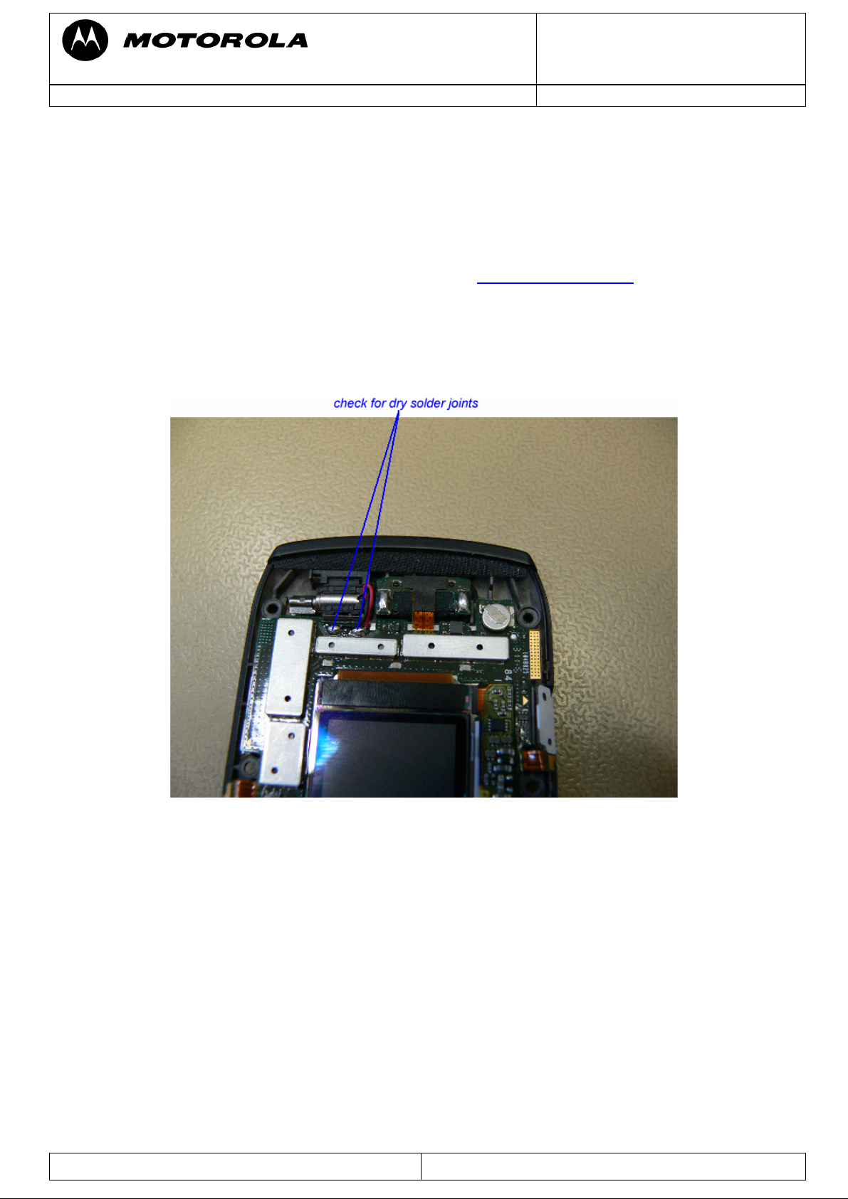
No ring tone/alert function
Check LOUD_SPM (M4000) and LOUD_SPP (M4001), both should have around 2.2Vdc.
- If not, check
FL4100, VS4001 and capacitors C4104, C4502, C4501, C4108 for
misplaced/ defective parts.
- If ok, change ATLAS IC
Figure
18
U3000.
The alert signal is amplified by the ATLAS IC and generated by the ARGON IC. If the ATLAS
alert audio path is ok, there could be a problem with the ARGON not generating the alert
signals – forward to authorized level 4 service center.
Repair Support Information
Figure 19
© Copyright 2003-2007 Motorola Inc. All Rights reserved.
Motorola internal use
Page 19

Doc. No: TSG_3G_V6
Version: 1.0
Motorola GmbH, Mobile Devices, CSS Center
Date: 23.07.2007
Title: Troubleshooting-Guide MotoRAZR maxx V6 Page: 19 / 40
No vibrator function
Turn on vibrator via RepairStudio/Radiocomm. Measure VVIB_1_3V at J2300-19, it should
be 3Vdc.
- If ok check
J2300 for defective part/ dry solder joints
- If not ok, change ATLAS IC
-
U3000.
Figure 20
Repair Support Information
© Copyright 2003-2007 Motorola Inc. All Rights reserved.
Motorola internal use
Page 20

Doc. No: TSG_3G_V6
Version: 1.0
Motorola GmbH, Mobile Devices, CSS Center
Date: 23.07.2007
Title: Troubleshooting-Guide MotoRAZR maxx V6 Page: 20 / 40
No display/-backlight/poor picture quality
Make sure that the problem is not located in the flip assembly, by testing PCB with a good
one and do a visual check of
J2300.
The following supply voltages for the flip assembly should be present:
-
B+
-
VCAM
-
VGPU_CORE_1_5V
-
VLVIO_1_8V
-
VHVIO_2_775V
The voltages can be ok without a flip connected, but can break down, if a flip is plugged in,
although the flip is ok! Additionally check the clock signal:
APPS_CLK at E2310 (should be 26Mhz)
-
only present the first seconds after power on!
If ok check:
- Filters
FL2300, FL2301, FL2302, FL2303, FL2304
You can check the function of these parts by using an Ohm Meter to check the resistance to
GND for verification, which line is affected. By using MotoPCB, it can be tracked which filter
the signal passes until it reaches the ARGON.
If all of these are ok, it should most likely be a problem with the ARGON
U1000 – forward to
an authorized level 4 service center.
We have seen some phones with the symptom: After a few seconds after turn on the display
seems to loose synchronization as shown on Figure 19. In most cases this issue was caused
by a skewed
E2310. In some cases the PCB was damaged because of lifted pads. It seems
to be damaged by a poor disassembly process.
Repair Support Information
Figure 21
© Copyright 2003-2007 Motorola Inc. All Rights reserved.
Motorola internal use
Page 21

Doc. No: TSG_3G_V6
Version: 1.0
Motorola GmbH, Mobile Devices, CSS Center
Date: 23.07.2007
Title: Troubleshooting-Guide MotoRAZR maxx V6 Page: 21 / 40
Flip detect problem
Units with a flip detect problem will show following symptoms:
- no power on via battery
- no main display via EMU connector supply
- CLI display is not switching on open/close flip
- No keypad function
Check
FLIP_DETECT_F at R2316-2 – should be 1.8Vdc (High signal), if it is low check
VIPU_1_8V at R2316-1. If 1.8Vdc are present check J2300/FL2306 for dry solder
joints/solder shorts/defective part – if ok it is most likely a problem with the ARGON
forward to an authorized level 4 service center.
U1000 –
Figure 22
Repair Support Information
© Copyright 2003-2007 Motorola Inc. All Rights reserved.
Motorola internal use
Page 22

Doc. No: TSG_3G_V6
Version: 1.0
Motorola GmbH, Mobile Devices, CSS Center
Date: 23.07.2007
Title: Troubleshooting-Guide MotoRAZR maxx V6 Page: 22 / 40
Keypad/side keys – no function/hangs
Due to the keypad matrix architecture with 8 rows in 8 columns it is quite useful to verify
which keys (if not all) are affected. By knowing which keys are not working, it is possible to
find out which row or column is affected. You can use an Ohm Meter to check the resistance
to GND for verification, which line is affected. By using the MotoPCB it can be tracked which
filters the signal passes until it reaches the ARGON.
Figure 23
In practice the defective part can very often be found by doing a visual inspection. Check:
J2300
-
-
FL2305
-
FL2306
-
FL2307 for solder shorts/dry solder joints/defective part.
If the keypad connector/filters are ok, it’s most likely a problem with the ARGON – forward to
an authorized level 4 service center.
Repair Support Information
Figure 24
© Copyright 2003-2007 Motorola Inc. All Rights reserved.
Motorola internal use
Page 23

Doc. No: TSG_3G_V6
Version: 1.0
Motorola GmbH, Mobile Devices, CSS Center
Date: 23.07.2007
Title: Troubleshooting-Guide MotoRAZR maxx V6 Page: 23 / 40
On/Off switch not working
The On/Off button function can easily be checked by attaching a known good flip assembly
to the PCB. By inserting an EMU Bus USB cable the phone should turn on. Check
ON_OFF_END_B at FL2307-8. It should be a HIGH signal of 2.8Vdc and LOW signal if
Button is pressed.
- If signal is at HIGH level and not switching down when On/Off button is pressed,
check
- If signal is always at LOW level or down (below 2.8Vdc), check
are ok, it is most likely a problem with the ATLAS IC
J2300 and FL2307.
R3993/C3955. If they
U3000.
Repair Support Information
Figure 25
© Copyright 2003-2007 Motorola Inc. All Rights reserved.
Motorola internal use
Page 24

Doc. No: TSG_3G_V6
Version: 1.0
Motorola GmbH, Mobile Devices, CSS Center
Date: 23.07.2007
Title: Troubleshooting-Guide MotoRAZR maxx V6 Page: 24 / 40
No keypad backlight
Keypad lighting is done by EL. The EL driver is located on the keyboard PCB. Turn on
keypad backlight via RepairStudio/Radiocomm. Check
- if
ELEN1 is HIGH, check J2300
- If
ELEN1 is LOW, it is most likely a problem with the ARGON U1000 – forward to an
ELEN1,
authorized level 4 service center.
Figure 26
Repair Support Information
© Copyright 2003-2007 Motorola Inc. All Rights reserved.
Motorola internal use
Page 25

Doc. No: TSG_3G_V6
Version: 1.0
Motorola GmbH, Mobile Devices, CSS Center
Date: 23.07.2007
Title: Troubleshooting-Guide MotoRAZR maxx V6 Page: 25 / 40
SIM card – check card/insert SIM
Measurement on the SIM interface is a little bit difficult, as not all signals will be present until
a SIM card and a battery are inserted. As far as we know, there is still no SIM feature
implementation in RepairStudio or Radiocomm. In the most cases it should be possible to
figure out which part is defective by simply using an Ohm Meter to measure the following
signals to GND:
-
VSIM at M5500-3, M5500-5
If far less than 30 kOhm to GND, it could be a defective ATLAS IC
USIM_CLK_1 at M5500-1
-
-
USIM_RST_1 at M5500-2
-
USIM_IO_1 at M5500-6
U3000.
If any of these has far less than 30 kOhm to GND, it could be a defective ARGON IC
– forward to an authorized level 4 service center.
U1000
Before replacing the ATLAS IC
U3000 or the ARGON U1000, make sure that none of the
associated capacitors/diodes have low resistance to GND.
Repair Support Information
Figure 27
© Copyright 2003-2007 Motorola Inc. All Rights reserved.
Motorola internal use
Page 26

Doc. No: TSG_3G_V6
Version: 1.0
Motorola GmbH, Mobile Devices, CSS Center
Date: 23.07.2007
Title: Troubleshooting-Guide MotoRAZR maxx V6 Page: 26 / 40
TransFlash Memory Card – no function
Insert a known good TransFlash card.
Under Menu – Settings – Phone Status – Storage Devices the Memory Card should
appear next to the internal phone memory.
If not, disassemble the phone and do a visual inspection of the TransFlash Connector
J5801
itself. If there are any visible damages/bent contacts/solder shorts or dry joints, change it.
Check
SD1_DET_B at R5811-1:
- Without TransFlash card inserted there should be a HIGH signal of 1.9Vdc, if not
check
R5811 for dry solder joints/tombstoned part.
- With TransFlash card inserted the signal should change to LOW signal (0V)
If
SD1_DET_B without TransFlash card inserted is ok (HIGH/1.9Vdc), but is not switching
down to 0V with inserted TransFlash card, replace TransFlash connector
Check
ok, it is probably a problem with the ARGON
VMMC_2_9V at R5801-1 (2.9Vdc). If low, check VR5801 for internal short to GND. If
U1000 – forward to an authorized level 4
J5801.
service center.
Repair Support Information
Figure 28
© Copyright 2003-2007 Motorola Inc. All Rights reserved.
Motorola internal use
Page 27

Doc. No: TSG_3G_V6
Version: 1.0
Motorola GmbH, Mobile Devices, CSS Center
Date: 23.07.2007
Title: Troubleshooting-Guide MotoRAZR maxx V6 Page: 27 / 40
No turn on
Verify if radio doesn’t turn on (assembled with display). If it does, but doesn’t enumerate via
EMU-Connector at RSD/RepairStudio there should be a problem with the USB connection.
In some cases a 1FF SW reflash in
FORCED FLASH MODE (by connecting EMU-Connector
to radio while “*” and “#” are pressed) can fix this issue.
- If not, visually check EMU-Connector
J5000 for mechanical defects or contamination
on contacts, bad soldered pins or solder shorts
- Check
- If ok, change ATLAS IC
D5002/C5001/C5002 for internal short to GND, R3650/R3651 (22 Ohm)
U3000
If the problem remains, it could be a problem with the ARGON IC
authorized level 4 service center.
U1000 – forward to an
Repair Support Information
Figure 29
© Copyright 2003-2007 Motorola Inc. All Rights reserved.
Motorola internal use
Page 28

Doc. No: TSG_3G_V6
Version: 1.0
Motorola GmbH, Mobile Devices, CSS Center
Date: 23.07.2007
Title: Troubleshooting-Guide MotoRAZR maxx V6 Page: 28 / 40
If radio doesn’t turn on, but draws high current (>500 mA)
- Please follow troubleshooting instructions as described in the Battery life
short/Charging problems/No turn on due to excessive current drain section of this
document.
If radio draws no current it’s most likely a problem with the 32.768 KHz clock generated by
Y3986.
- Change crystal
Y3986. (It might be difficult replacing Y3986 without damaging the
underfilled ATLAS IC U3000. Wherever possible try using a solder iron instead of the
heatgun)
- If unsuccessful change ATLAS IC
U3000.
If the current consumption is in normal range (40mA to 300mA), try doing a 1FF SW reflash
in
FORCED FLASH MODE. If radio enters the forced flash mode or starts in flash mode by
itself the main supply voltages for the logic section should be ok. Most likely the trouble can
be found in the logic section (ARGON/Flash Memory) – forward to an authorized level 4
service center.
If the radio won’t give any sign of life with a current consumption of about 160 to 170mA for
less than a second, dropping to ~ 12mA it is a problem with the ARGON
an authorized level 4 service center.
Repair Support Information
Figure 30
U1000 – forward to
© Copyright 2003-2007 Motorola Inc. All Rights reserved.
Motorola internal use
Page 29

Doc. No: TSG_3G_V6
Version: 1.0
Motorola GmbH, Mobile Devices, CSS Center
Date: 23.07.2007
Title: Troubleshooting-Guide MotoRAZR maxx V6 Page: 29 / 40
Turn off – powers down in standby
If radio stores panic: DSM_MEASUREMENT_ERROR there is most likely a problem with the
32.768 KHz clock, on which the radio is running while entering the deep sleep mode.
- Change
Y3986 and test radio with a network SIM card and let radio entering the deep
sleep mode
- If radio still powers down, change ATLAS IC
U3000
If radio soft resets/power cycles and turns on again (possibly with a blank/white screen) try
doing a software upgrade with latest operator approved software. If the trouble remains, it
could be a problem with the ATLAS IC
U3000 or with the ARGON U1000 – forward to an
authorized level 4 service center.
Battery life short/charging problems/no turn on due to excessive current drain
In probably most cases these problems are caused by an off current. Start with verifying,
whether there is an off current. If there is an off current, it should be checked whether the
radio draws current via battery and/or via external power supply (USB).
In case of an off current via battery there should be a low resistance (less than ~200 Ohm)/
or a short from
BATT+_RAW (J5400-1) to GND.
To localize the defective part causing the short/low resistance a simple but effective way is to
freeze the board with a coolant spray, supply a battery voltage from a power supply using
micro clamp-type test probes, and see which parts are getting warm. This is a very basic
and essential method to troubleshoot off current/ high current consumption failures.
The power supply (for
BATT+_RAW) should be set to 3.8Vdc with current limitation set to 2A.
We recommend using the Power Supply Unit current drain meter to check the current drain
of the PCB.
Shields covering suspected parts should be removed before freezing the PCB.
The PCB should be handled with care. After removing the shields the PCB should be given
some time to cool down slowly before freezing it to far below zero to avoid physical stress to
the multilayer PCB with lead free soldered parts.
In some cases the part, which is getting warm has an internal short itself. After removing this
part, the off current should be fixed. For verification, check off current or measure resistance
BATT+_RAW (J5400-1) to GND. A new part can be placed.
If the short/ low resistance remains after replacing the part which was getting warm, it should
be checked which signals/ voltages this part provides. In most cases this part will provide a
supply voltage to other parts which can also get warm due to an internal short.
Repair Support Information
© Copyright 2003-2007 Motorola Inc. All Rights reserved.
Motorola internal use
Page 30

Doc. No: TSG_3G_V6
Version: 1.0
Motorola GmbH, Mobile Devices, CSS Center
Date: 23.07.2007
Title: Troubleshooting-Guide MotoRAZR maxx V6 Page: 30 / 40
Does not charge
If the phone seems to charge, but battery meter stays at low level, check whether there is a
high current consumption or an off current via battery. If so, follow troubleshooting as
described in the
Battery life short/charging problems/no turn on due to excessive current
drain section of this document.
If there is no off current, check the whole path for the charging current. Make a
battery/charger phasing to see, if only the charger current or additionally the battery phasing
is affected. For a charger current problem only:
- Check the whole charger path for misplaced parts/solder shorts/defective parts
- If ok, replace ATLAS IC U3000
Repair Support Information
Figure 31
© Copyright 2003-2007 Motorola Inc. All Rights reserved.
Motorola internal use
Page 31

Doc. No: TSG_3G_V6
Version: 1.0
Motorola GmbH, Mobile Devices, CSS Center
Date: 23.07.2007
Title: Troubleshooting-Guide MotoRAZR maxx V6 Page: 31 / 40
Invalid Battery
Check
R5400/R5401 for misplaced part.
Verify
2.775V. If it is low, check
BATT_DAT at J5400-2 while PCB is connected via EMU USB cable. It should be
BATT_DAT at R5400-2, if it is 2.775V here, change/resolder J5400.
In any other case it is most likely a problem with the ARGON
authorized level 4 service center.
U1000 – forward to an
Figure 32
Repair Support Information
© Copyright 2003-2007 Motorola Inc. All Rights reserved.
Motorola internal use
Page 32

Doc. No: TSG_3G_V6
Version: 1.0
Motorola GmbH, Mobile Devices, CSS Center
Date: 23.07.2007
Title: Troubleshooting-Guide MotoRAZR maxx V6 Page: 32 / 40
Battery Thermistor problem
Because the signals which could be measured are not accessible without removing the
ATLAS shield
the best way to start with replacing the battery connector
replace additionally the ATLAS IC
SH1009 (which would damage the underfilled ATLAS IC U3000), it is probably
J5400. If the trouble remains
U3000.
For replacement of the battery connector J5400 the air cooling device for protecting
the ATLAS IC should be used.
Repair Support Information
Figure 33
© Copyright 2003-2007 Motorola Inc. All Rights reserved.
Motorola internal use
Page 33

Doc. No: TSG_3G_V6
Version: 1.0
Motorola GmbH, Mobile Devices, CSS Center
Date: 23.07.2007
Title: Troubleshooting-Guide MotoRAZR maxx V6 Page: 33 / 40
Accessory detection problem
Some phones do not detect connected accessories (Charger/Headset). Those phones will
turn on if connected to a charger (instead of entering charging mode). If so
- check
- If less than 1MOhm
USB_ID (J5000-4) to GND with an ohmmeter
D5002 should be removed.
- If still less than 1MOhm it should be because of a defective ATLAS IC, replace
U3000.
A new diode array
D5002 has to be placed after successful repair.
Figure 34
Repair Support Information
© Copyright 2003-2007 Motorola Inc. All Rights reserved.
Motorola internal use
Page 34

Doc. No: TSG_3G_V6
Version: 1.0
Motorola GmbH, Mobile Devices, CSS Center
Date: 23.07.2007
Title: Troubleshooting-Guide MotoRAZR maxx V6 Page: 34 / 40
Can’t make voice call/no service
First step in every call related problem should be to figure out whether there is a receiving
problem or a transmitting problems and which bands are affected.
Make sure that the RF connectors
M001/M002 are cleaned (with cleaner or alcohol) before
making a phasing/call processing test or if the test fails.
No or low TX output power in GSM
Check the connection to the antenna to ensure it is properly plugged. Prior to remove any
shields for measurements, visually inspect the antenna circuit for skewed/misplaced parts.
Figure 35
Let radio transmit on GSM900 using RepairStudio/Radiocomm. Make sure to provide a
battery voltage via micro clamp-type test probes to battery contacts
J5400.
Measure the power at the output of the GSM PA
If output power
- Check to see if PA
- Check the input power
EGSM_OUT from PA is low
U800 is soldered down properly
TX_LB_IN to the PA from TransAAM at C841-1
Figure 36
U800 at R804-1.
Repair Support Information
© Copyright 2003-2007 Motorola Inc. All Rights reserved.
Motorola internal use
Page 35

Doc. No: TSG_3G_V6
Version: 1.0
Motorola GmbH, Mobile Devices, CSS Center
Date: 23.07.2007
Title: Troubleshooting-Guide MotoRAZR maxx V6 Page: 35 / 40
- If input power to PA is low it is most likely a problem with the TransAAM
- If input power to PA is ok it is most likely a problem with the PA
If output power
EGSM_OUT from PA is good the trouble is most likely related to a bad FEM
U800 itself.
U500.
U001 (do a visual check for misplaced parts around FEM U001).
GSM TX signals:
TX_LB_IN and TX_HB_IN: modulated input TX signal from TransAAM
-
-
IPC_BCM: mode switch between GMSK and EDGE. Currently BCM is associated
with GMSK mode and should be logic 0. In EDGE mode, IPC mode is selected and
should be logic 1:
-
TX_LB_HB_IN: mode switch between LB and HB. LB is logic 0 and HB logic 1
-
VRAMP: voltage that controls PA operation. If probed with an oscilloscope, you will
see signals close to a rectangular pulse of value 1.8V to 2.2V for max power output
-
PAC_DET: power detector with voltage reading corresponds to VRAMP value
-
TX_EN: logic signal that enables the PA
-
GSM_TCXO: 26MHz clock for TransAAM
TX Supply voltages
VRF_TX_2_775V
-
-
BATT+
-
LVDD
-
JVDD
-
QVDD_1_8
-
VDDA_2_7
-
VDDA_CP_2_7
-
VDD_ACE_2_7
-
VDD_TXRX_2_7
Repair Support Information
© Copyright 2003-2007 Motorola Inc. All Rights reserved.
Motorola internal use
Page 36

Doc. No: TSG_3G_V6
Version: 1.0
Motorola GmbH, Mobile Devices, CSS Center
Date: 23.07.2007
Title: Troubleshooting-Guide MotoRAZR maxx V6 Page: 36 / 40
No or low TX output power in WCDMA
Let radio transmit on WCDMA using RepairStudio/Radiocomm. Make sure to provide a
battery voltage via micro clamp-type tests probes to battery contacts
J5400.
Measure the power at the output of the WCDMA PA
If output power
- Check to see if PA
- Check the input power
PA_2100_RF_OUT from WCDMA PA is low
U400 is soldered down properly
TX_WB_2100 to the PA from SYMPHONY at C408-1
U400 at R400-1.
Figure 37
- If input power to PA is low it is most likely a problem with the SYMPHONY U100.
- If input power to PA is ok it is most likely a problem with the PA
If output power
FEM
U001 (do a visual check for misplaced parts around FEM U001).
PA_2100_RF_OUT from PA is good the trouble is most likely related to a bad
U400 itself.
WCDMA TX signals
TX_WB_2100: modulated input TX signal from SYMPHONY
-
-
PA_2100_EN: logic signal that enables the WCDMA PA
-
PA_VBA: controls the gain of the WCDMA PA
-
PA_VDET: power detect signal
-
PASSKEY_VLD: determines two modes of operation: - Hi Power Mode/Low Power
Mode
WCDMA TX supply voltages
VRF_TX_2_775V
-
-
BATT+
-
VRFCP_2_775V
-
VHVIO_2_2_775V
-
VRF_LVIO_1_875V
-
VMELODY_CORE
-
VRF_RX_2_775VV
Repair Support Information
© Copyright 2003-2007 Motorola Inc. All Rights reserved.
Motorola internal use
Page 37

Doc. No: TSG_3G_V6
Version: 1.0
Motorola GmbH, Mobile Devices, CSS Center
Date: 23.07.2007
Title: Troubleshooting-Guide MotoRAZR maxx V6 Page: 37 / 40
No RX GSM
Inject a RF from Test Set. The power level should be set to max power. Check ANT_FEM at
antenna switch
M001-1. Check for presence of GSM_RX_IN at C524-2.
- If not ok replace FEM
U001
- If ok there is most likely a problem with the SAW Filter
the ARGON
U1000 – forward to an authorized level 4 service center.
FL500, the TransAAM U500 or
Note: For AFC phasing the receiver is used. So, if there is any RX fail, the AFC phasing on
that frequency band also fails. If the RX phasing is ok, but only AFC phasing fails, a bad
crystal is the most likely cause – replace
In addition the FEM state after FEM logic table can be checked. If one of them is missing, it
is most likely a problem with the ARGON U1000 – forward to an authorized level 4 service
center.
Repair Support Information
Figure 38
Y190.
Figure 39
© Copyright 2003-2007 Motorola Inc. All Rights reserved.
Motorola internal use
Page 38

Doc. No: TSG_3G_V6
Version: 1.0
Motorola GmbH, Mobile Devices, CSS Center
Date: 23.07.2007
Title: Troubleshooting-Guide MotoRAZR maxx V6 Page: 38 / 40
No RX WCDMA
WCDMA RX is diplexed with Bluetooth TX/RX and uses the secondary antenna
M002.
The diplexer performance is dependent on both the WCDMA RX and Bluetooth sides of the
circuit. Bluetooth components (
FL5600, C5627, C5628 and L5628) must all be properly
placed for the WCDMA RX to function properly. Visually inspect these components when
presented with a WCDMA RX front-end failure.
Figure 40
Visually inspect WCDMA diplexer components (L012, L13 and C10)
Figure 41
If a unit passes performance testing at 12.2k but fails at a higher data rate, the issue is
typically caused by the SYMPHONY
U100 or the ARGON U1000 – forward to an authorized
level 4 service center.
Check RX signal path from connector
If ok, suspect SYMPHONY. Also check
Inject a RF from Test Set. The power level should be set to max power. Check
antenna switch
M002-1.
Repair Support Information
M002 to SYMPHONY inputs, look for misplaced parts.
26MHz TCXO and surrounding components.
BT_RF_IN at
© Copyright 2003-2007 Motorola Inc. All Rights reserved.
Motorola internal use
Page 39

Doc. No: TSG_3G_V6
Version: 1.0
Motorola GmbH, Mobile Devices, CSS Center
Date: 23.07.2007
Title: Troubleshooting-Guide MotoRAZR maxx V6 Page: 39 / 40
- If bad, replace
- Check for presence of
- Check
RX_WB_2100_NEG/RX_WB_2100_POS at R305, if ok in size and form (if
unsure compare with a known good PCB) suspect the SYMPHONY
- If
RX_WB_2100_NEG/RX_WB_2100_POS are not ok, check VRF_RX_2_775V at
M002
2100_PREFILT_OUT at FL001-1, if bad replace FL001
U100
R304, if ok check/replace U300/FL300
Repair Support Information
Figure 42
© Copyright 2003-2007 Motorola Inc. All Rights reserved.
Motorola internal use
Page 40

Doc. No: TSG_3G_V6
Version: 1.0
Motorola GmbH, Mobile Devices, CSS Center
Date: 23.07.2007
Title: Troubleshooting-Guide MotoRAZR maxx V6 Page: 40 / 40
Flash procedures
Note: It is very important to do a restart after every flash process! Otherwise the phone may
start in flash mode again.
Software update
Following steps are necessary to update the Software to latest approved Software:
- unlock phone (if subsidy locked)
- flash customer specific 1FF superfile (example:
R26117LD_U_98.20.33BR_LP0039_DRM1003_VSTU_207_0C_JPUK_R26117VOLANSVF_
03_USVOLANSVFUKR26117062_1FF.sbf
)
- after restart:
- take out of “In Factory” – if necessary
- do Master Reset/Master Clear
Recovering Flash Memory in Forced Flash Mode
If the phone doesn’t start because of corrupted software it might be possible to recover it:
DC One File Flash:
- connect phone to EMU-cable while pressing “*” and “#”
The phone should start in flash mode now: S Flash Argon.
- flash 1FF superfile (example:
R26117LD_U_98.20.33BR_LP0039_DRM1003_VSTU_207_0C_JPUK_R26117VOLANSVF_
03_USVOLANSVFUKR26117062_1FF.sbf
DC One File Flash:
)
- after restart:
- do Master Reset/Master Clear
If the phone doesn’t start in flash mode, there is a problem –
troubleshooting.
proceed to level 3
Repair Support Information
© Copyright 2003-2007 Motorola Inc. All Rights reserved.
Motorola internal use
 Loading...