

Motorola V551, V555, V530 Service Manual
Level 1 and 2 Service Manual
V551/V555 GSM
Quad-Band Wireless Telephone
GSM 850/900/1800/1900 MHz
EDGE


1 and 2
Level 1 and 2 Service Manual Contents
6809490A38-O
V551 GSM
Contents
Contents . . . . . . . . . . . . . . . . . . . . . . . . . . . . . . . . . . . . . . . . . . . . . . . . . . . . . . . . . . . . . . . . . . . . . . . . . . . . . . . . . . . . 1
Introduction . . . . . . . . . . . . . . . . . . . . . . . . . . . . . . . . . . . . . . . . . . . . . . . . . . . . . . . . . . . . . . . . . . . . . . . . . . . . . . . . . 3
Product Identification . . . . . . . . . . . . . . . . . . . . . . . . . . . . . . . . . . . . . . . . . . . . . . . . . . . . . . . . . . . . . . . . . . . 3
Product Names . . . . . . . . . . . . . . . . . . . . . . . . . . . . . . . . . . . . . . . . . . . . . . . . . . . . . . . . . . . . . . . . . . . . . . . . 3
Regulatory Agency Compliance . . . . . . . . . . . . . . . . . . . . . . . . . . . . . . . . . . . . . . . . . . . . . . . . . . . . . . . . . . . 3
Computer Program Copyrights . . . . . . . . . . . . . . . . . . . . . . . . . . . . . . . . . . . . . . . . . . . . . . . . . . . . . . . . . . . 4
About this Service Manual . . . . . . . . . . . . . . . . . . . . . . . . . . . . . . . . . . . . . . . . . . . . . . . . . . . . . . . . . . . . . . . 4
Warranty Service Policy . . . . . . . . . . . . . . . . . . . . . . . . . . . . . . . . . . . . . . . . . . . . . . . . . . . . . . . . . . . . . . . . . 5
Parts Replacement . . . . . . . . . . . . . . . . . . . . . . . . . . . . . . . . . . . . . . . . . . . . . . . . . . . . . . . . . . . . . . . . . . . . . 6
Specifications . . . . . . . . . . . . . . . . . . . . . . . . . . . . . . . . . . . . . . . . . . . . . . . . . . . . . . . . . . . . . . . . . . . . . . . . . . . . . . 7
Product Overview . . . . . . . . . . . . . . . . . . . . . . . . . . . . . . . . . . . . . . . . . . . . . . . . . . . . . . . . . . . . . . . . . . . . . . . . . . . . 9
Features . . . . . . . . . . . . . . . . . . . . . . . . . . . . . . . . . . . . . . . . . . . . . . . . . . . . . . . . . . . . . . . . . . . . . . . . . . . . . . 9
General Operation . . . . . . . . . . . . . . . . . . . . . . . . . . . . . . . . . . . . . . . . . . . . . . . . . . . . . . . . . . . . . . . . . . . . . . . . . . . 11
Controls, Indicators, and Input/Output (I/O) Connectors . . . . . . . . . . . . . . . . . . . . . . . . . . . . . . . . . . . . . 11
User Interface Menu Structure . . . . . . . . . . . . . . . . . . . . . . . . . . . . . . . . . . . . . . . . . . . . . . . . . . . . . . . . . . 12
Alert Settings . . . . . . . . . . . . . . . . . . . . . . . . . . . . . . . . . . . . . . . . . . . . . . . . . . . . . . . . . . . . . . . . . . . . . . . . 14
Battery Function . . . . . . . . . . . . . . . . . . . . . . . . . . . . . . . . . . . . . . . . . . . . . . . . . . . . . . . . . . . . . . . . . . . . . . 14
Operation . . . . . . . . . . . . . . . . . . . . . . . . . . . . . . . . . . . . . . . . . . . . . . . . . . . . . . . . . . . . . . . . . . . . . . . . . . . . 14
Tools and Test Equipment . . . . . . . . . . . . . . . . . . . . . . . . . . . . . . . . . . . . . . . . . . . . . . . . . . . . . . . . . . . . . . . . . . . . 15
Disassembly . . . . . . . . . . . . . . . . . . . . . . . . . . . . . . . . . . . . . . . . . . . . . . . . . . . . . . . . . . . . . . . . . . . . . . . . . . . . . . . . 16
Removing and Replacing the Battery Cover . . . . . . . . . . . . . . . . . . . . . . . . . . . . . . . . . . . . . . . . . . . . . . . . 16
Removing and Replacing the Battery . . . . . . . . . . . . . . . . . . . . . . . . . . . . . . . . . . . . . . . . . . . . . . . . . . . . . 17
Removing and Replacing the SIM Card . . . . . . . . . . . . . . . . . . . . . . . . . . . . . . . . . . . . . . . . . . . . . . . . . . . 18
Removing and Replacing the Antenna . . . . . . . . . . . . . . . . . . . . . . . . . . . . . . . . . . . . . . . . . . . . . . . . . . . . 19
Removing and Replacing the Rear Housing . . . . . . . . . . . . . . . . . . . . . . . . . . . . . . . . . . . . . . . . . . . . . . . . 20
Removing and Replacing the Transceiver PC Board . . . . . . . . . . . . . . . . . . . . . . . . . . . . . . . . . . . . . . . . . 21
Removing and Replacing the Keypad . . . . . . . . . . . . . . . . . . . . . . . . . . . . . . . . . . . . . . . . . . . . . . . . . . . . . 22
Removing and Replacing the Microphone . . . . . . . . . . . . . . . . . . . . . . . . . . . . . . . . . . . . . . . . . . . . . . . . . . 23
Removing and Replacing the Flip Assembly . . . . . . . . . . . . . . . . . . . . . . . . . . . . . . . . . . . . . . . . . . . . . . . . 24
Removing and Replacing the Front Flip Cover . . . . . . . . . . . . . . . . . . . . . . . . . . . . . . . . . . . . . . . . . . . . . . 25
Removing and Replacing the Metal Flip Shield . . . . . . . . . . . . . . . . . . . . . . . . . . . . . . . . . . . . . . . . . . . . . 26
Removing and Replacing the Camera . . . . . . . . . . . . . . . . . . . . . . . . . . . . . . . . . . . . . . . . . . . . . . . . . . . . . 27
Removing and Replacing the Flip/Vibrator Motor Flex . . . . . . . . . . . . . . . . . . . . . . . . . . . . . . . . . . . . . . . 28
Removing and Replacing the Display Assembly . . . . . . . . . . . . . . . . . . . . . . . . . . . . . . . . . . . . . . . . . . . . . 29
Telephone Identification . . . . . . . . . . . . . . . . . . . . . . . . . . . . . . . . . . . . . . . . . . . . . . . . . . . . . . . . . . . . . . . . . . . . . . 30
Identification Label . . . . . . . . . . . . . . . . . . . . . . . . . . . . . . . . . . . . . . . . . . . . . . . . . . . . . . . . . . . . . . . . . . . . 30
Troubleshooting . . . . . . . . . . . . . . . . . . . . . . . . . . . . . . . . . . . . . . . . . . . . . . . . . . . . . . . . . . . . . . . . . . . . . . . . . . . . 31
Manual Test Mode . . . . . . . . . . . . . . . . . . . . . . . . . . . . . . . . . . . . . . . . . . . . . . . . . . . . . . . . . . . . . . . . . . . . 31
Manual Test Mode Commands . . . . . . . . . . . . . . . . . . . . . . . . . . . . . . . . . . . . . . . . . . . . . . . . . . . . . . . . . . . 31
Troubleshooting Chart . . . . . . . . . . . . . . . . . . . . . . . . . . . . . . . . . . . . . . . . . . . . . . . . . . . . . . . . . . . . . . . . . 33
. . . . . . . . . . . . . . . . . . . . . . . . . . . . . . . . . . . . . . . . . . . . . . . . . . . . . . . . . . . . . . . . . . . . . . . . . . . . . . . . . . . . 35
Programming: Software Upgrade and Flexing . . . . . . . . . . . . . . . . . . . . . . . . . . . . . . . . . . . . . . . . . . . . . . 35
Part Numbers . . . . . . . . . . . . . . . . . . . . . . . . . . . . . . . . . . . . . . . . . . . . . . . . . . . . . . . . . . . . . . . . . . . . . . . . . . . . . . . 36
Exploded View Diagram . . . . . . . . . . . . . . . . . . . . . . . . . . . . . . . . . . . . . . . . . . . . . . . . . . . . . . . . . . . . . . . . 36
Exploded View Parts List . . . . . . . . . . . . . . . . . . . . . . . . . . . . . . . . . . . . . . . . . . . . . . . . . . . . . . . . . . . . . . 37
Accessories . . . . . . . . . . . . . . . . . . . . . . . . . . . . . . . . . . . . . . . . . . . . . . . . . . . . . . . . . . . . . . . . . . . . . . . . . . . 38
Related Publications . . . . . . . . . . . . . . . . . . . . . . . . . . . . . . . . . . . . . . . . . . . . . . . . . . . . . . . . . . . . . . . . . . . 39
Index . . . . . . . . . . . . . . . . . . . . . . . . . . . . . . . . . . . . . . . . . . . . . . . . . . . . . . . . . . . . . . . . . . . . . . . . . . . . . . . . . . . . . . 41
6809490A38-O September 28, 2004 1

Contents V551 GSM
2 September 28, 2004 6809490A38-O

1 and 2
Level 1 and 2 Service Manual Introduction
6809490A38-O
V551 GSM
Introduction
Motorola® Inc. maintains a worldwide organization that is dedicated to provide
responsive, full-service customer support. Motorola products are serviced by an
international network of company-operated product-care centers as well as
authorized independent service firms.
Available on a contract basis, Motorola Inc. offers comprehensive maintenance and
installation programs that enable customers to meet requirements for reliable,
continuous communications.
To learn more about the wide range of Motorola service programs, contact your local
Motorola products representative or the nearest Customer Service Manager.
Product Identification
Motorola products are identified by the model number on the housing. Use the entire
model number when inquiring about the product. Numbers are also assigned to
chassis and kits. Use these numbers when requesting information or ordering
replacement parts.
Product Names
Product name included in V551/V555 telephone is listed on the front cover. Product
names are subject to change without notice. Some product names, as well as some
frequency bands, are available only in certain markets.
Regulatory Agency Compliance
This device complies with Part 15 of the FCC Rules. Operation is subject to the
following conditions:
• This device may not cause any harmful interference, and
• must accept interference received, including interference that may cause
undesired operation.
This class B device also complies with all requirements of the Canadian
Interference-Causing Equipment Regulations (ICES-003).
Cet appareil numérique de la classe B respecte toutes les exigences du Règlement
sur le matériel brouilleur du Canada.
6809490A38-O September 28, 2004 3

Introduction V551 GSM
Computer Program Copyrights
The Motorola products described in this manual may include Motorola computer
programs stored in semiconductor memories or other media that are copyrighted
with all rights reserved worldwide to Motorola. Laws in the United States and other
countries preserve for Motorola, Inc. certain exclusive rights to the copyrighted
computer programs, including the exclusive right to copy, reproduce, modify,
decompile, disassemble, and reverse-engineer the Motorola computer programs in
any manner or form without Motorola's prior written consent. Furthermore, the
purchase of Motorola products shall not be deemed to grant either directly or by
implication, estoppel, or otherwise, any license or rights under the copyrights,
patents, or patent applications of Motorola, except for a nonexclusive license to use
the Motorola product and the Motorola computer programs with the Motorola
product.
About this Service Manual
Using this service manual and the suggestions contained in it assures proper
installation, operation, and maintenance of the V551/V555 telephone. Refer
questions about this manual to the nearest Customer Service Manager.
Audience
This manual aids service personnel in testing and repairing the V551/V555
telephone. Service personnel should be familiar with electronic assembly, testing,
and troubleshooting methods, and with the operation and use of associated test
equipment.
Use of this manual assures proper installation, operation, and maintenance of
Motorola products and equipment. It contains all service information required for
the equipment described and is current as of the printing date.
Scope
The scope of this manual is to provide basic information relating to the V551/V555
telephone, and provide procedures and processes for repairing the phone at Level
1 and 2 service centers including:
•Unit swap out
• Repairing of mechanical faults
• Basic modular troubleshooting
•Testing and verification of phone functionality
• Initiate warranty claims and send faulty modules to Level 3 or 4 repair
centers
4 September 28, 2004 6809490A38-O

Level 1 and 2 Service Manual Introduction
Conventions
Special characters and typefaces, listed and described below, are used in this
manual to emphasize certain types of information.
➧
G
E
Warranty Service Policy
This product is sold with the standard 12-month warranty terms and conditions.
Accidental damage, misuse, and extended warranties offered by retailers are not
supported under warranty. Non-warranty repairs are available at agreed fixed
repair prices.
M
Note: Emphasizes additional information pertinent to the subject
matter.
Caution: Emphasizes information about actions that may result in
equipment damage.
Warning: Emphasizes information about actions that may result in
personal injury.
Keys to be pressed are represented graphically. For example, instead of “Press
the Menu Key”, you will see “Press
Information from a screen is shown in text as similar as possible to what
appears in the display. For example,
Information that you need to type is printed in boldface type
M”.
ALERTS or ALERTS.
Out of Box Failure Policy
The standard out of box failure criteria applies. Customer phones that fail very
early on after the date of sale, are to be returned to Manufacturing for root-cause
analysis, to guard against epidemic criteria. Manufacturing will bear the costs of
early life failure.
Product Support
Customer’s original phone will be repaired but not refurbished as standard.
Appointed Motorola Service Hubs will perform warranty and non-warranty field
service for level 2 (assemblies) and level 3 (limited PCB component). The Motorola
High Technology Centers will perform level 4 (full component) repairs.
Customer Support
Customer support is available through dedicated Call Centers and in-country help
desks. Product Service training should be arranged through the local Motorola
Support Center.
6809490A38-O September 28, 2004 5

Introduction V551 GSM
Parts Replacement
When ordering replacement parts or equipment, include the Motorola part number
and description used in the service manual.
When the Motorola part number of a component is not known, use the product model
number or other related major assembly along with a description of the related
major assembly and of the component in question.
In the U.S.A., to contact Motorola, Inc. on your TTY, call: 800-793-7834
Accessories and Aftermarket Division (AAD)
Replacement parts, test equipment, and manuals can be ordered from AAD.
U.S.A. Outside U.S.A.
Phone: 800-422-4210 Phone: 847-538-8023
FAX: 800-622-6210 FAX: 847-576-3023
To order spare parts in EMEA region call +49 461 803 1638.
To order spare parts in Asia region call +65 648 62995.
6 September 28, 2004 6809490A38-O
Level 1 and 2 Service Manual Specifications
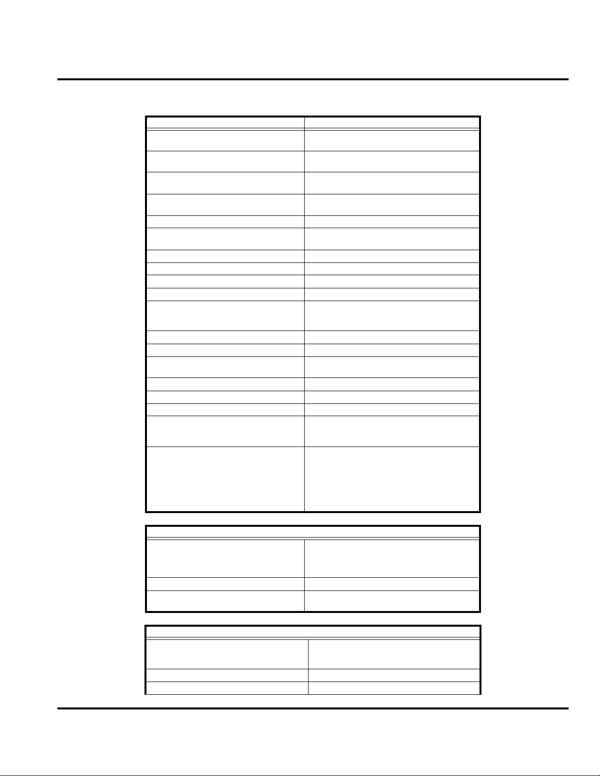
Specifications
General Function Specification
Frequency Range GSM 850
Frequency Range GSM 900
Frequency Range DCS 1800
Frequency Range PCS 1900
Channel Spacing 200 kHz
Channels
Modulation GMSK at BT = 0.3
Transmitter Phase Accuracy 5 Degrees RMS, 20 Degrees peak
Duplex Spacing 45 MHz GSM, 95 MHz DCS, 80 MHz PCS
Frequency Stability ± 0.10 ppm of the downlink frequency (Rx)
Operating Voltage
Average Transmit Current 310 mA max
Average Stand-by Current 4.0 mA max (DRX2), 3.0 mA max (DRX9)
Dimensions
Size (Volume) 89 cc (5.43 in
Weight 110 gm (3.5 oz) with cell
Temperature Range -10° C to +55° C (+15° F to +130° F)
Battery Life, 790 mAh Li Ion Battery Talk time 220 - 425 mins
824-848 MHz Tx
869-893 MHz Rx
880-915 MHz Tx (with EGSM)
925-960 MHZ Rx
1710-1785 MHz Tx
1805-1880 MHz Rx
1850-1910 MHz Tx
1930-1990 MHz Rx
174 EGSM, 374 DCS, 374 PCS, carriers
with 8 channels per carrier
+3.0V dc to +4.2V dc (cell)
+4.4V dc to +6.6V dc (external charger jack
with 2.4 K ohm resistor)
108mm x 46mm x 20.5mm
(4.25 inches x 1.81 inches x 0.81 inches)
3
)
Standby time 180 - 225 Hrs.
All talk and standby times are approximate
and depend on network configuration,
signal strength, and features selected.
Standby times are quoted as a range from
DRX=2 to DRX=9. Talk times are quoted
as a range from 50% DTX high power to
low power.
Transmitter Specification
33 dBm nominal GSM 850
RF Power Output
Output Impedance 50 ohms nominal
Spurious Emissions
Receiver Specification
Receive Sensitivity
RX bit error rate (100k bits) Type II < 2%
Channel Hop Time 500 microseconds
33 dBm nominal GSM 900
30 dBm nominal GSM 1800
30 dBm nominal GSM 1900
-36 dBm from 0.1 to 1 GHz,
-30 dBm from 1 to 4 GHz
-106 dBm GSM 900,
-104 dBm GSM 1800,
-104 dBm PCS
6809490A38-O September 28, 2004 7
Specifications V551 GSM
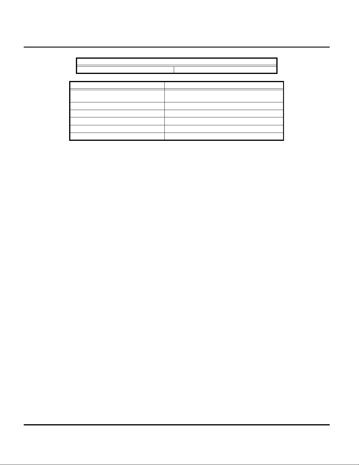
Receiver Specification
Time to Camp Approximately 5-10 seconds
Speech Coding Function Specification
Speech Coding Type
Bit Rate 13.0 kbps
Frame Duration 20 ms
Block Length 260 bits
Classes Class 1 bits = 182 bits; Class 2 bits = 78 bits
Bit Rate with FEC Encoding 22.8 kbps
Regular pulse excitation / linear predictive coding
with long term prediction (RPE LPC with LTP)
8 September 28, 2004 6809490A38-O

Level 1 and 2 Service Manual Product Overview
Product Overview
Motorola V551/V555 telephones are small and lightweight global system for mobile
communications (GSM) general packet radio service (GPRS) wireless application
protocol (WAP)-enabled mobile phones and enhanced Data Rate for Global
Evolution (EDGE). The V551/V555 incorporate a new user interface (UI) for easier
operation, allows short message service (SMS) text messaging, and includes
personal information manager (PIM) functionality.
The V551/V555 is a quad-band phone that allows roaming within the GSM 900
MHz, (DCS) 1800 MHz digital cellular system, the GSM 850 MHz, and PCS 1900
MHz bands.
V551/V555 telephones support EDGE in addition to traditional circuit switched
transport technologies.
V551/V555 telephones have a clam form factor. They feature an externally viewable
96 x 32 pixel display for caller identification and date/time, an internal 176 x 220
pixel display, and single speakers located in the flip. The bottom part of the clam
(front housing) contains the keypad, transceiver printed circuit board (PCB),
microphone, flex connection, external accessory connector, smart button, volume
buttons, and voice button. The standard 790 mAh Lithium Ion (Li Ion) battery fits
behind a removable back cover.
The phone accepts both 1.875V and 3V mini subscriber identity module (SIM) cards
which fit into the SIM holder underneath the battery. The antenna is a fixed stub
type antenna. Inexpensive direct connection to a computer or handheld device via
RS232 or USB for data and fax calls, and for synchronizing phonebook entries with
TrueSync® software, can be accomplished by using the optional data cable and soft
modem.
Features
V551/V555 telephones use advanced, self-contained, sealed, custom integrated
circuits to perform the complex functions required for EDGE communication. Aside
from the space and weight advantage, microcircuits enhance basic reliability,
simplify maintenance, and provide a wide variety of operational functions.
Features available in this family of telephones include:
• Integrated high audio hands-free speakerphone
• Dedicated on off speakerphone button
• Quad-Band
• Multi-Media Messaging (MMS)
• Integrated digital camera (VGA quality) with zoom and brightness adjustment
• One polyphonic speaker w/ MP3, MIDI, & WAV ringers
• Stylish and Ergonomic design
• 5 megabytes of end user memory
• Large, active color display (176 x 220, 65K)
• External CLI display (96x32, with blue backlight)
• Games (embedded & downloadable)
• PIM functionality with Picture Caller ID
• Downloadable themes (ringers, images, animations)
6809490A38-O September 28, 2004 9

Product Overview V551 GSM
Personal Information Management
The V551/V555 telephone contains a built-in datebook with alarm reminders,
message center, and a phonebook.
Other Features
Detailed descriptions of other features available for the V551/V555 wireless
telephone are in the appropriate V551/V555 GSM User’s Guide listed in the Related
Publications section toward the end of this manual.
10 September 28, 2004 6809490A38-O
Level 1 and 2 Service Manual General Operation
General Operation
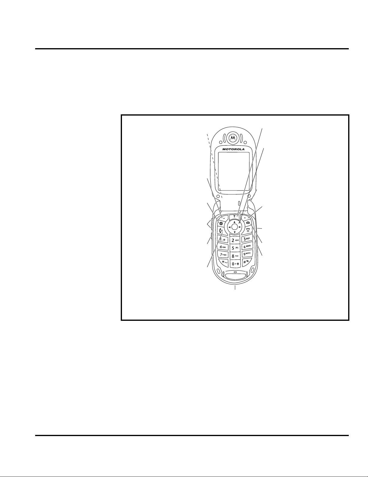
Controls, Indicators, and Input/Output (I/O) Connectors
The V551/V555 telephone controls are on the front of the device and on the keyboard
as shown in Figure 1. Indicator icons are displayed on the LCD (see Figure 2).
Headphone
Connector
Left Soft Key
Perform function
in lower left
display.
Browser Key
Volume Keys
Smart Key
Send Key
Make & answer
calls.
040488a
Accessory
Connector
Menu Key
5-Way
Navigation Key
Scroll to items.
Right Soft Key
Perform function
in lower right
display.
Voice Key
Camera Key
Power & End
Key
Turn phone
on/off, end calls,
exit menu
system.
Figure 1. Controls and Indicators
Menu Navigation
The V551/V555 telephone has a simplified icon and GUI. See Figure 3 for the V551/
V555 menu structure. A scroll key allows you to move easily through menus.
Liquid Crystal Display (LCD)
The V551/V555 phone features a 176 x 220 color display offering 3 lines of text, 1
line of icons, and 1 line of prompts. The display provides constant graphical
representations of battery capacity and signal strength, as well as the real-time
clock.
6809490A38-O September 28, 2004 11
General Operation V551 GSM
Display animation makes the phone’s icon menu move smoothly as you scroll up
and down.
Whether a phone displays all indicators depends on the programming and services
➧
to which the user subscribes.
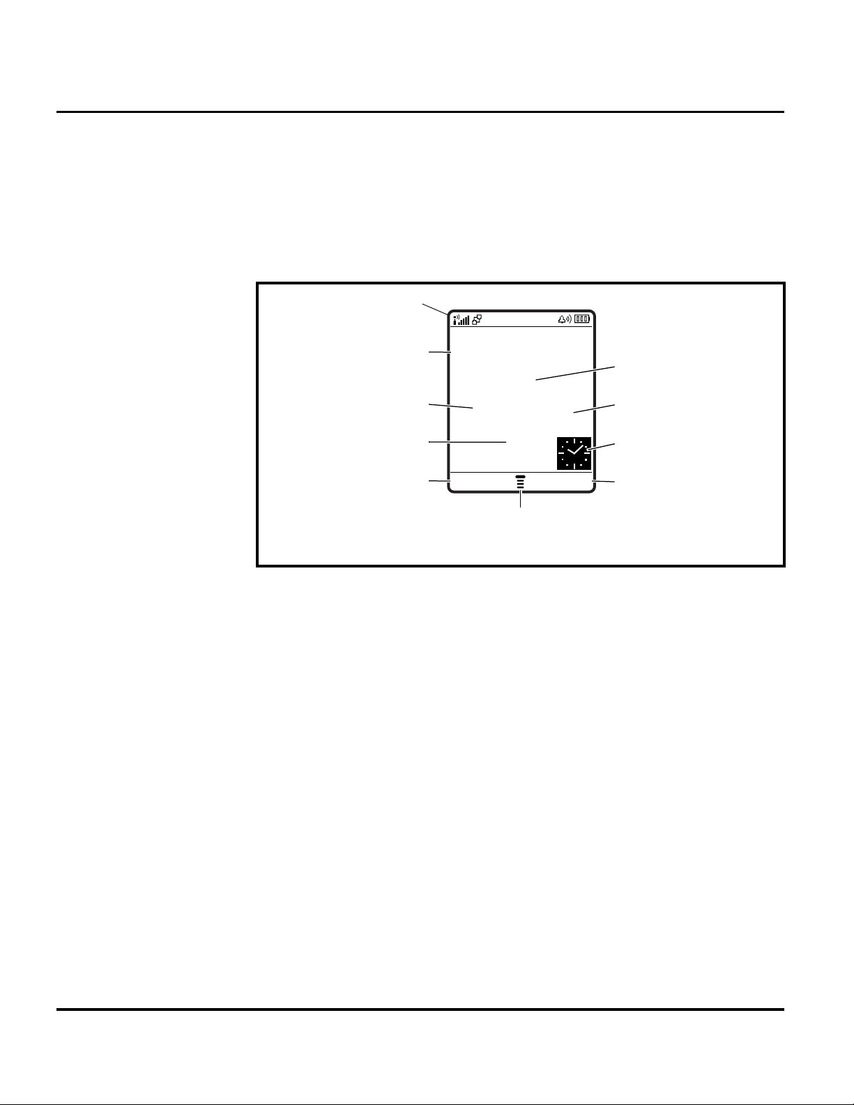
Figure 2 shows common icons displayed on the LCD.
Status Icons
—
Date Messages
Service Provider
10/15/03
Figure 2. V551/V555 Display Idle Screen
1. Status Icons show the status of your phone.
2. Real-Time Clock shows the current time.
3. Date shows the current date.
4. Soft Key Labels provide selectable options in screen display.
User Interface Menu Structure
Figure 3 shows the V551/V555 telephone menu structure.
Recent Calls
Phonebook
Left Soft Key
Label
e
s
à
n
STYLES CAMERA
Menu Indicator
Browser
Clock
Right Soft Key
Label
12 September 28, 2004 6809490A38-O
 Loading...