


Motorola V300, V500, V600 Service Manual
Triplets Theory of Operation
Level 3
Rel ease 1. 0
M odel V600/ V500/ V300
PCS 1900MHz/DCS 1800MHz/GSM 900MHz/GSM 850MHz

Distribution Policy and Copyright
Copyright
© 2003 by Motorola. All rights reserved. No part of this publication may be reproduced, transmitted,
transcribed, stored in a retrieval system or translated into any language in any form by any means
without the written permission of Motorola.
Software License
The Agreement sets forth the license terms and conditions for using the enclosed Software. You may
use this Software on a single computer, and you may transfer it to another computer as long as it is
used on only one computer at a time. You may copy the Software for backup purposes only. You may
not rent, sell, lease, sublicense, time-share or lend the Software to a third party or otherwise transfer
this License without written consent of Motorola. You shall not decompile, disassemble, reverseengineer or modify the Software. This License is effective until terminated. You may terminate it at any
time by destroying the Software together with all copies. The License also terminates if you fail to
comply with the terms and conditions of this Agreement. United States copyright laws as well as
international treaty provisions protect this Software and accompanying documentation. Any use of the
Software in violation of these laws constitutes termination of the License.
Limited Liability
The Software and accompanying documentation is provided “AS IS” without warranty of any kind.
Motorola specifically disclaims all other warranties, expressed or implied, including but not limited to
implied warranties of merchantability and fitness for a particular purpose. With respect to the use of
this product, in no event shall Motorola be liable for any loss of profit or any other commercial damage,
including but not limited to special, incidental, consequential or other damages.
ii
Motorola Confidential Proprietary
Release 1.0

Table of Contents
Theory of Operation ...................................................................................................................... 5
Introduction ................................................................................................................................ 5
Figure 1. V600/V500/V303/V300 ..................................................................................................................5
Antenna Circuit .......................................................................................................................... 6
Figure 2. Radiated RF ..................................................................................................................................6
Figure 3. Conducted RF ...............................................................................................................................6
Eagle 9G.................................................................................................................................... 7
Algae MB ................................................................................................................................... 7
Figure 4. Eagle-9G Functional Block............................................................................................................7
Figure 5. Algae MB Receiver .......................................................................................................................7
Figure 6. Algae MB Transmitter ....................................................................................................................8
Power Distribution...................................................................................................................... 8
Figure 7. PCAP Regulators - 1 .....................................................................................................................8
Figure 8. PCAP Regulators - 2 .....................................................................................................................8
Clock Generation .......................................................................................................................9
Figure 9. PCAP 32kHz Clock.......................................................................................................................9
PCAP TX Audio ......................................................................................................................... 9
Figure 10. TX Audio Functional Block ........................................................................................................10
PCAP RX Audio ...................................................................................................................... 10
Figure 11. RX Audio Functional Block........................................................................................................11
Battery Interface .......................................................................................................................12
Figure 12. Charger Functional Block .......................................................................................................... 12
Neptune LTE............................................................................................................................ 13
Figure 13. Neptune LTE Functional Block .................................................................................................. 13
Memory Interface...................................................................................................................... 14
Ke ypad Interf ace ......................................................................................................................14
SIM Interface ............................................................................................................................14
Figure 14. SIM Interface ............................................................................................................................14
Bluetooth (V600/V500 only)..................................................................................................... 15
Figure 15. Bluetooth System Block............................................................................................................15
Flip Interface ............................................................................................................................ 17
Figure 16. Flip Display Module ................................................................................................................... 17
Block Diagram ......................................................................................................................... 18
Figure 17. V600/V300 RF Block Diag ram ...................................................................................................18
©2003 Motorola, Inc.
iiiRelease 1.0

Triplets Theory of Operation (Level 3)Table of Contents
iv
©2003 Motorola, Inc.
Theory of Operation
Introduction
Motorola V600/V300 telephones are small and lightweight global system for mobile communications (GSM)
general packet radio service (GPRS) wireless application protocol (WAP)-enabled mobile phones. The
V600/V300 incorporates a new user interface (UI) for
easier operation, allows short message service (SMS)
text messaging, and includes personal information manager (PIM) functionality. The supported bands for each
phone are listed below.
V600
• GSM 850/900/1800/1900 MHz GPRS (2U/
4D)
V300
• GSM 900/1800/1900 MHz GPRS (2U/4D)
• GSM 850/900/1900 MHz GPRS (2U/4D)
• GSM 850/1800/1900 MHz GPRS (2U/4D)
dard battery capacity is 650 mAh, for V600 is 750
mAh.
The phone accepts both 3V and 5V mini subscriber
identity module (SIM) cards which fit into the SIM
holder underneath the battery. The antenna is a fixed
stub type antenna. Inexpensive direct connection to a
computer or handheld device via RS232 or USB for
data and fax calls, and for synchronizing phonebook
entries with TrueSync® software, can be accomplished
by using the optional data cable and soft modem.
V600/V300 telephones use advanced, self-contained,
sealed, custom integrated circuits to perform the complex functions required for GSM GPRS communication. Aside from the space and weight advantage, microcircuits enhance basic reliability, simplify maintenance,
and provide a wide variety of operational functions.
V600/V300 telephones support GPRS and SMS in addition to traditional circuit switched transport technologies.
V600/V300 telephones have a clam form factor. They
have an externally viewable 96 x 32 pixel display for
caller identification and date/time, an internal 176 x 220
pixel display, and the speaker located in the flip. The
bottom part of the clam (front housing) contains the
keypad, transceiver printed circuit board (PCB), microphone, flex connection, external accessory connector, smart button, volume buttons, and voice button.
The standard Lithium Ion (Li Ion) battery fits behind a
removable back cover. For V300/V303/V500, stan-
Release 1.0
Motorola Confidential Proprietary
Figure 1. V600/V500/V303/V300
V300 V303/V500 V600
5
Antenna Circuit
Triplets Theory of Operation (Level 3)
Features available in this family of telephones include:
• GSM 850/900/1800/1900 MHz GPRS (2U/
4D)
• Built in VGA Camera (640x480 pixels)
• 65K TFT Active Color Display
• External CLI Display (Transflective Reversed)
• Polyphonic Speaker
• Speaker Phone
• Bluetooth™ (V600 only)
• Metal Housings (V600 only)
• Changeable covers (V600 only)
• Situation Lights (V600 only)
• Video Clip Playback (V600 only)
• 5MB User Memory
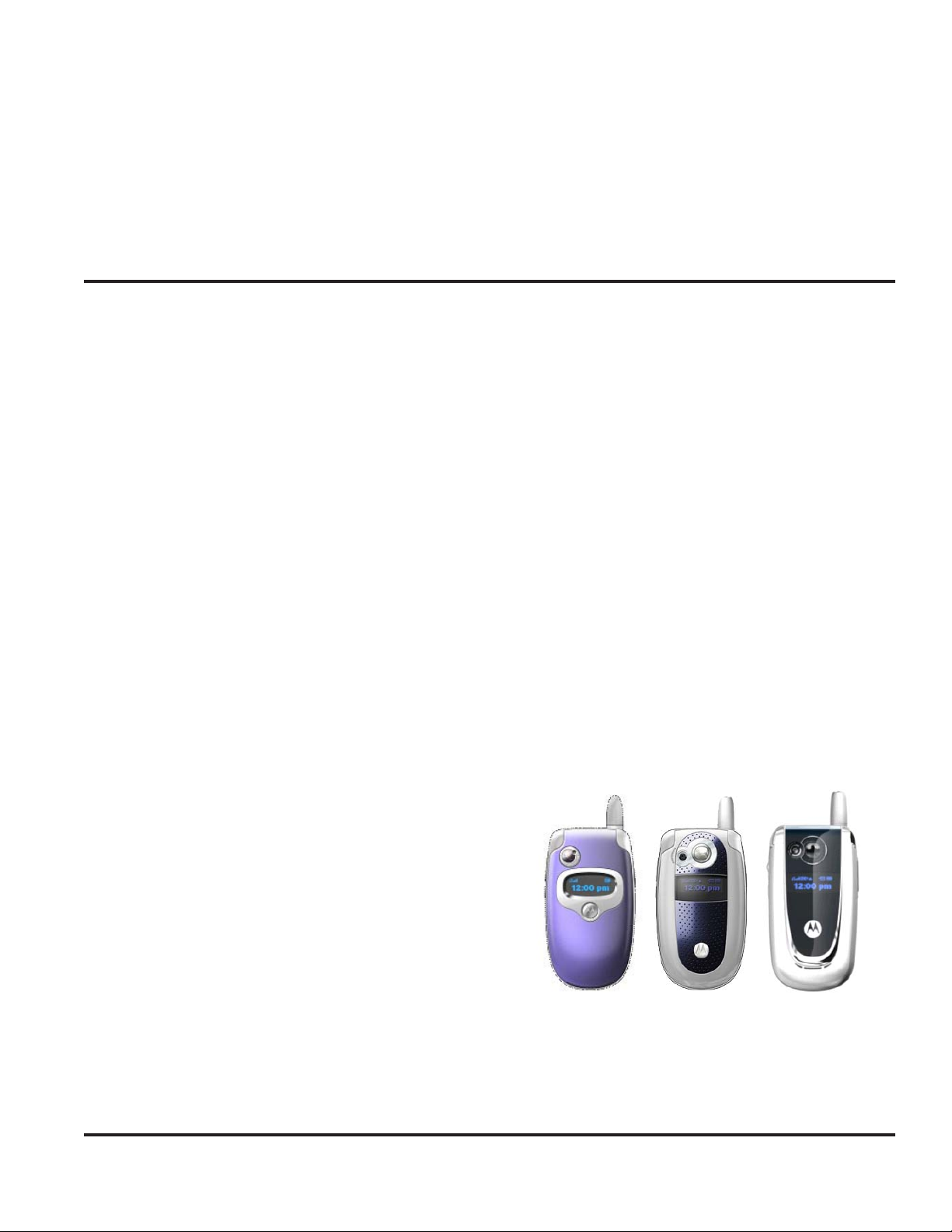
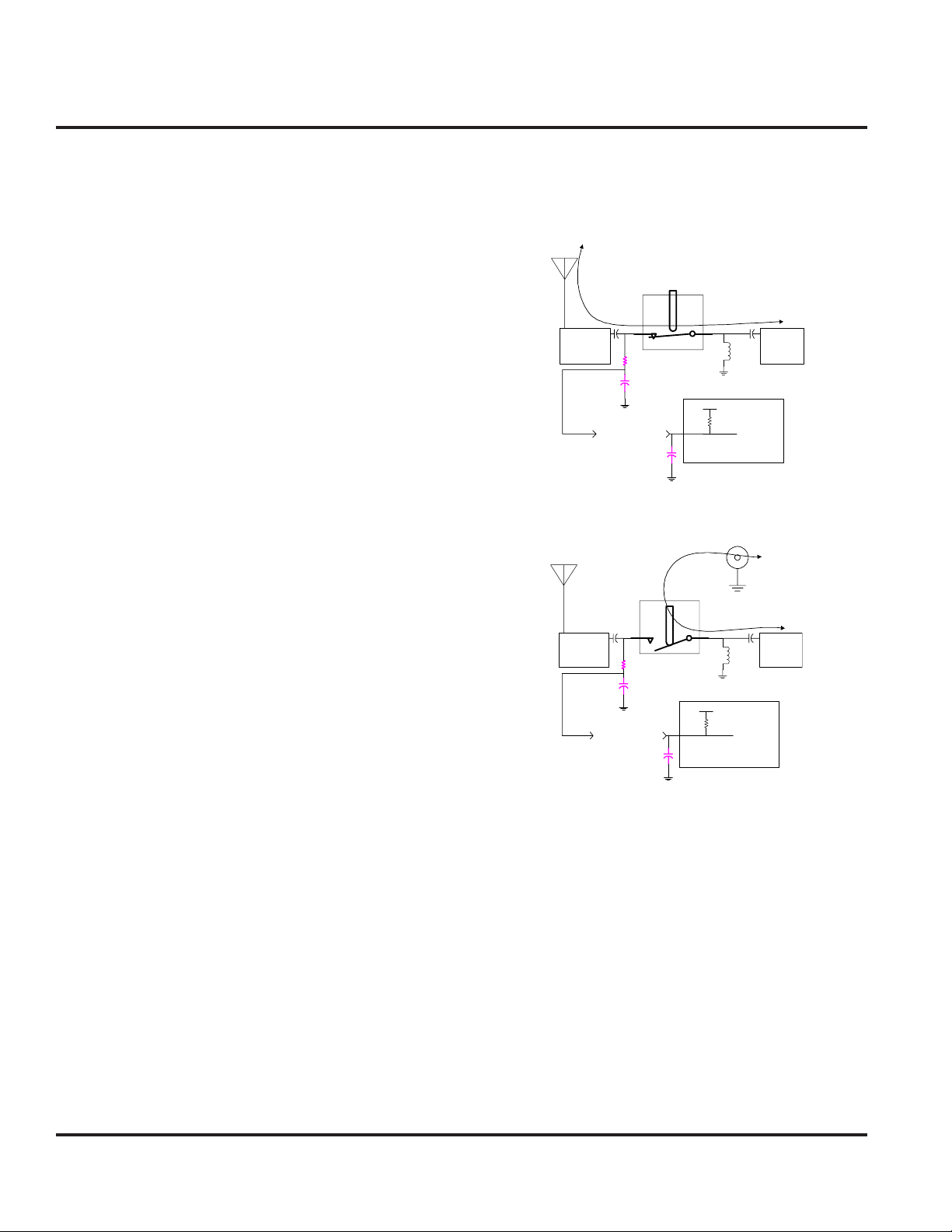
Antenna Circuit
In order for the phone to report accurate receive level
of an incoming signal, the efficiency of the antenna must
be taken into account. When a cabled accessory connection is made the plane of reference is shifted to the
connector and RX level measurements need to be adjusted accordingly.
The signal ANT_DETB is normally low when a connection to the antenna is present. This signal alerts the
software to account for a phased offset to accurately
reflect the power of an incoming signal at the antenna.
When a cabled accessory is inserted, the path to ground
is broken and a pull-up resistor to VDD asserts the
ANT_DETB line and signals that the plane of reference
is now the accessory port.
then switched to an output that is always asserted low
to eliminate current drain.
Figure 2. Radiated RF
Mechanical
Accessory
1000 pF
RF switch
Transceiver
board's T/R
Static
protection
inductor
DVDD
69K Internal pull up resistor
Neptune LTS/LTEMicro Processor
switch
RF path
Antenna matching
22K ohm
100 pF
To Neptune for
AccessoryRF detection.
Figure 3. Conducted RF
Accessory Cable
RF path
Mechanical
Accessory
RFswitch
Antenna matching
22K ohm
100 pF
To Neptune for
Accessory RFdetection .
1000 pF
DVDD
69KI nternalpull up resistor
Neptune LTS/LTE MicroProcessor
Stat ic
protection
inductor
Transceiver
board'sT/R
switch
Since the signal is normally low and is shunted to ground
via a resistive path, the 69 kohm pull-up resistor inside
the Neptune LTS / LTE maintains a steady state current
drain that is unacceptable for deep sleep requirements.
Therefore the ANT_DETB line is configured as a bidirectional line, where it is an input during the time it is
begin polled to determine if an antenna is present, and
6
Motorola Confidential Proprietary
Release 1.0
 Loading...